

mabe EML27WWF0, JBS27DILWW, JCB535DILBB, JCB535DILWW, EML535NNF0,EML535BBF0,EML535NXF0,EML735BBF0 Service Manual
...Page 1
Ingeniería de Servicio
MODEL SERIES:
EML27WWF0 JBS27DILWW EML27NXF0 JBS27RILSS
JCB535DILWW JCB535DILBB JCB535SILSS JCB735DILWW
JCB735DILBB JCB735SILSS JCB835DILWW JCB835SILSS
EML535NNF0 EML535BBF0 EML535NXF0 EML735BBF0
EML735NNF0 EML735NXF0 EML835BBF0 EML835NXF0
Service manual
Page 2

Ingeniería de Servicio
Important Safety Instructions, Warnings and Recommendations 3
Nomenclature 4
Models 7
Features 8
Tools needed 13
Technical information 14
Installation instructions 15
Using controls 21
List of main components 44
Disassemble and retrofit 45
Electric diagrams 62
Failures and solutions 67
Index
Page 3

Ingeniería de Servicio
IMPORTANT SAFETY NOTICE
The information on this document is directed to
service individuals who possess accurated
knowledge and electrical, electronic and
mechanical experience. Any attempt to repair an
appliance could result in personal injury and
property damage. The manufacturer or seller
could not be held responsible for the
interpretation of this information, nor can it
assume any liability realted to its use.
WARNING
To avoid personal injury, disconnect power
before servicing this product. If electrical power is
required for diagnosis or for the purpose of
testing, disconnect power immediately after
carrying out the necessary checks.
RECONNECT ALL GROUNDING DEVICES
If grounding wires, screws, ribbons, hook, nuts or
washers used to complete a route to the ground
are removed for servicing, they must be returned
to their original position and must be properly
secured.
CLOTHING:
Required: Pants, shirt, cap safety shoes to
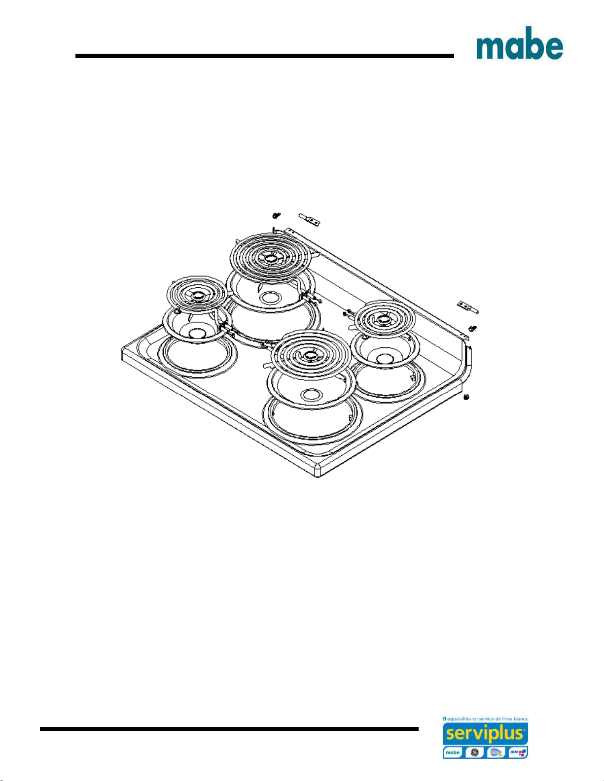
protect your feet from any sparks or hot metal
particles, do not work with tennis shoes.
Keep clothing free of grease or oil.
Important safety notices, warnings and recommendations
Page 4
Ingeniería de Servicio
4
E M L 5 3 5 N N F 0 A
Stove
Brand
M: Mabe
Electric
Feature level
535
735
835
S27
Color
NN: Black/Black
BB: White/White
WW: White/White
Voltage
220/ 240V
Design
Digit
chance
Generation
Digit
chance
Nomenclature
Page 5
Ingeniería de Servicio
5
J B S 2 7 D I L W W
Brand
J: GE
Space
Electric
range
Product type
Code
B: 30"
Feature level
L: 2017
Color
SS: Stainless steel
WW: White
BB: Black
NX: Stainless steel
Autoself
clean
D: Derivative color of BB/WW
R: Stainless with black accents
Voltage
220/ 240V
Page 6
Ingeniería de Servicio
6
J C B 5 3 5 S I L S S
Brand
J: GE
Fuel type
C: Electric
range
Product type
Code
B: 30"
Feature level
535
735
835
L: 2017
Color
SS: Stainless steel
WW: White
BB: Black
NX: Stainless steel
with black
Voltage
220/ 240V
D: Derivative color of BB/WW
S: Metalic
Page 7
Ingeniería de Servicio
7
EML27NXF0A
EML27WWF0A
EML535BBF0A
EML535NNF0A
EML535NXF0A
EML735BBF0A
EML735NNF0A
EML735NXF0A
EML835BBF0A
EML835NXF0A
JBS27DIL1WW
JBS27RIL1SS
JCB535DIL1BB
JCB535DIL1WW
JCB535SIL1SS
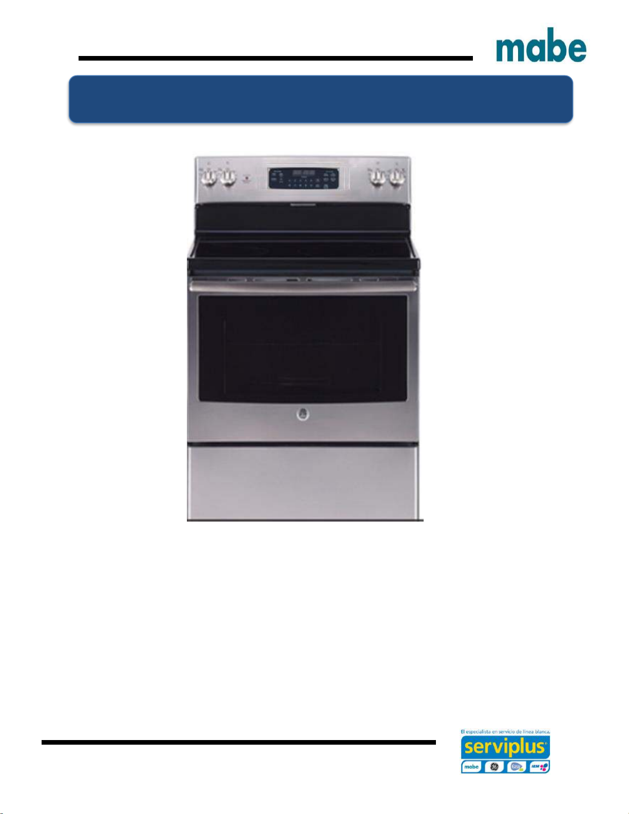
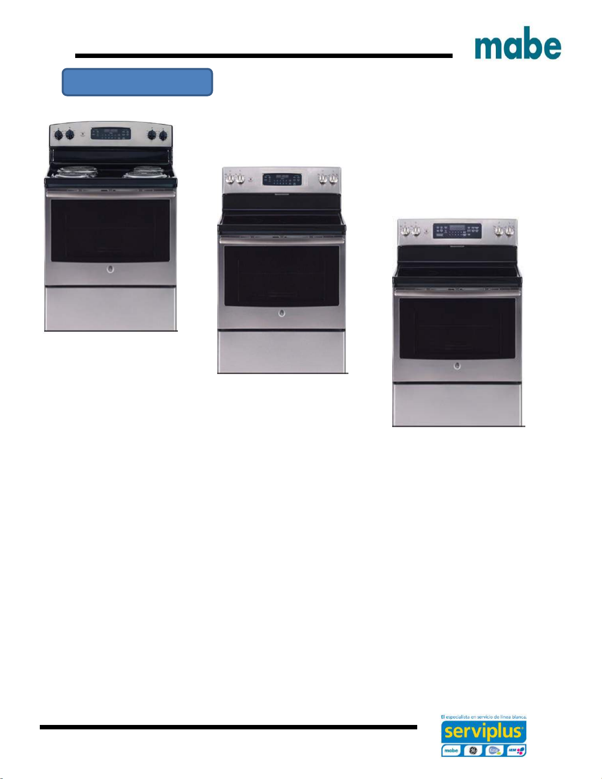
30" Freestanding electric ranges
4 Coil burners
30" Freestanding electric ranges
4 Radiant burners
EML27NXF0A 12" Dual element
EML27WWF0A
EML535BBF0A 30" Freestanding electric ranges
EML535NNF0A 5 Radiant burners
EML535NXF0A EML735BBF0A True convection air
JBS27DIL1WW EML735NNF0A
JBS27RIL1SS EML735NXF0A EML835BBF0A
JCB535DIL1BB JCB735DIL1BB EML835NXF0A
JCB535DIL1WW JCB735DIL1WW JCB835DIL1WW
JCB535SIL1SS JCB735SIL1SS JCB835SIL1SS
Models
Page 8
Ingeniería de Servicio
8
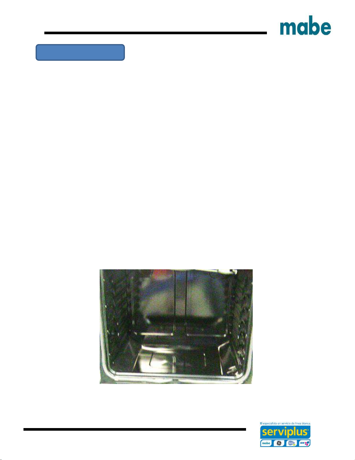
1. Back protector – seamless design
2. Double oven sensor
3. Triple ring elements
3. Full glass oven door design
4. TrueTemp ™
5. 6.2 Ft^3 Oven capacity
6. Increased usable capacity
7. Six position oven grill
8. Six-pass bake element
9. Full black interior design
10. New oven control design
11. New appereance design
Features
Page 9
Ingeniería de Servicio
9
Exclusive cleaning design
As for ease of cleaning, the clean oven interior design conceals the bottom heating element
beneath a steel surface coated with porcelain. All you see es a clean, smooth flat surface.
Convenient new option: Warming area
Maintains soups, sauces, breads and pancakes wam, melts chocolate.
Or use this new burner as you would any other element.
Page 10
Ingeniería de Servicio
10
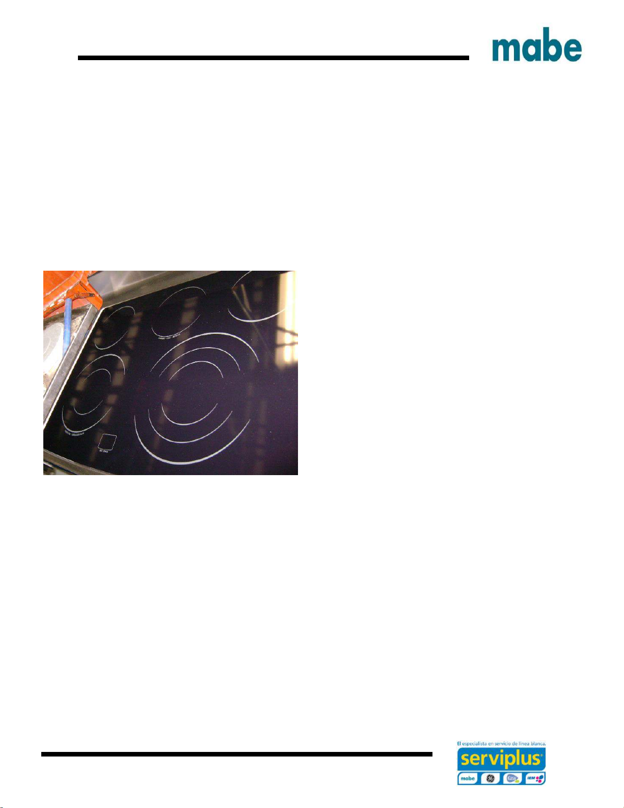
Features of the heating elements
Surface elements
EML835/ JCB835
6" element 240V 1260W
6" element 240V 1260W
6/9" element
Warming Zone 6"
9/12" element 240V 2520W
EML735/ JCB735
6" element 240V 1260W
6" element 240V 1260W
8" element
Warming Zone 6"
9/12" element 240V 2520W
Page 11
Ingeniería de Servicio
11
EML535/JCB535
EML27/JBS27
8" element 240V 2184W
6" element 240V 1260W
6" element 240V 1260W
8" element 240V 2184W
Page 12
Ingeniería de Servicio
12
Heating elements features
Oven elements
Page 13

Ingeniería de Servicio
13
Drill with 1/8 "Bit
Safety glasses
Safety gloves
Safety shoes
Adjustable Wrench
Flexometer
Pilers
1/4 " Hex Screw driver
Level
Torx T-15
Phillips screw driver
Multimeter
Tools needed
Page 14

Ingeniería de Servicio
14
See use and care manuals and diagrams according to the
corresponding model
DESCRIPTION PART NUMBER MODELS
USE AND CARE MANUAL 183D8379P086
EML27
JBS27
USE AND CARE MANUAL 183D8379P087
EML535
JCB535
EML735
JCB735
USE AND CARE MANUAL 183D8379P088
EML835
JCB835
MINI MANUAL 295D2661G004
EML835
JCB835
MINI MANUAL 295D2661G003
EML735
JCB735
MINI MANUAL 295D2661G002
EML535
JCB535
MINI MANUAL 295D2661G001
EML27
JBS27
SCHEMATIC DIAGRAM 295D2627P004
EML835
JCB835
SCHEMATIC DIAGRAM 295D2627P003
EML735
JCB735
SCHEMATIC DIAGRAM 295D2627P002
EML535
JCB535
SCHEMATIC DIAGRAM 295D2627P001
EML27
JBS27
INSTALLATION INSTRUCTION 222D3619P009
ALL
Technical information
Page 15
Ingeniería de Servicio
15
BEFORE YOU BEGIN
Read this instructions completely and carefully.
• IMPORTANT – Save this instructions for local inspector´s use.
• IMPORTANT – Observe all governing codes and ordinances.
• Note to installer – Be sure to leave these instructions with the consumer.
• Note to the consumer – Keep this instructions for future references.
• Skill level – Installation of this appliance requires an installer or electrician.
• Proper installation is the responsibility of the installer.
• Produc failure due to improper installation is not covered by warranty.
WARNING: This apppliance must be properly connected using the supplied cables.
WARNING: Before beginning installation, turn off the switch on the operator
panel and lock the service connection to prevent power from being switched on accidentally.
When disconnecting means can not be locked, securely fasten a prominent warning device, such
as a tag, to the service panel.
Installation instructions
Page 16

Ingeniería de Servicio
16
1.- REMOVE PACKAGING MATERIALS:
If the packaging materials are not removed may cause damage to the device. Remove all
packaging components from oven, racks, heating elements and drawer. Also, remove the
protective film and labels on the outside door, stove and rear guard.
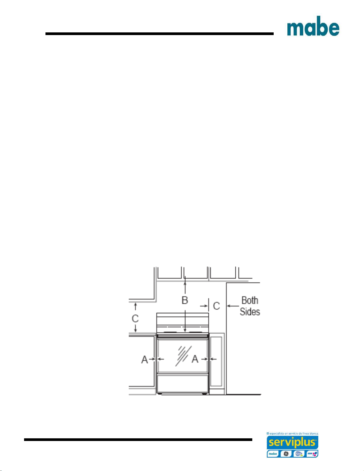
2. PREPARE THE OPENING
(For indoor use only)
See ilustrations for all rough-in spacing dimensions. The range may be placed with 0 cm
clearance (flush) at the back wall and side walls of the cabinet.
MINIMUM DISTANCE BETWEEN THE RANGE, WALLS AND ABOVE THE RANGE:
Page 17
Ingeniería de Servicio
17
A. Make sure that the wall covering, conter top, flooring and cabinets around the range can
withstand the heat (uo to 200°F) generated by the range.
B. Allow 76,2 cm ( 30 " ) minimum clearance between surface units and bottom of unprotected
wood or metal cabinet, or allow 61 cm ( 24 ") minimum when bottom of wood or etal cabinet is
protected by no less than 0,6 cm ( 1 / 4 " ) thick flame retardant milboard covered with not less
than No 28 MSG sheet metal, 0.38 mm ( 0.015 ") thinck stainless steel , 0.61 mm (0.024 ")
aluminum or 0.51mm (0.020 ") copper.
C. This apppliance has been approved for 0” minimum spacing to adjacent surfaces above the
cooktop. However, a 15.2 cm minimum spacing to surfaces less than 30.81 cm above the cooktop
and adjacent cabinets is recommended to reduce exposure to steam, grease and heat.
To reduce the risk of burns or fire when reaching over hot surface elements, cabinet storage
space above the cooktop should be avoided. If cabinet storage space is to be provided above the
cooktop, the risk can be reduced by installing a range hood that projects at least 12.7 cm beyoond
the front od the cabinets. Cabinets installed above the cooktop must be bo deeper than 33 cm.
Cuando el revestimiento del suelo termina en la parte delantera de la gama, el área que la gama
descansará y debe ser construido con madera contrachapada para el mismo nivel o más alto que
el revestimiento del suelo. Esto permitirá que la estufa sea movida para la limpieza o el
mantenimiento.
Page 18
Ingeniería de Servicio
18
3. ANTITIP BRACKET INSTALLATION
To reduce the risk of tipping the range, the range must be secured by a properly installed anti-tip
bracket. See installation instructions included with the bracket for complete details before
attempting to install.
To check if the bracket is installed and engaged properly, remove the storage drawer or kick panel
and look underneath the range to see that the leveling leg is engaged in the bracket. On models
without a storage drawer or kick panel, carefully tip the range forward. The bracket should stop
the range within 4 inches.
Otherwise, the bracket must be reinstalled. If the range is pulled from the wall for any reason,
always repeat this procedure to verify the range is properly secured by the anti-tip bracket. Never
completely remove the leveling legs or the range will not be secured to the anti-tip device properly.
4. LEVEL THE RANGE
WARNING: Never completely remove the leveling leg as the range will not be secured to the anti
tip device properly.
A. Install all the oven racks in the oven an position the range where it will be installed.
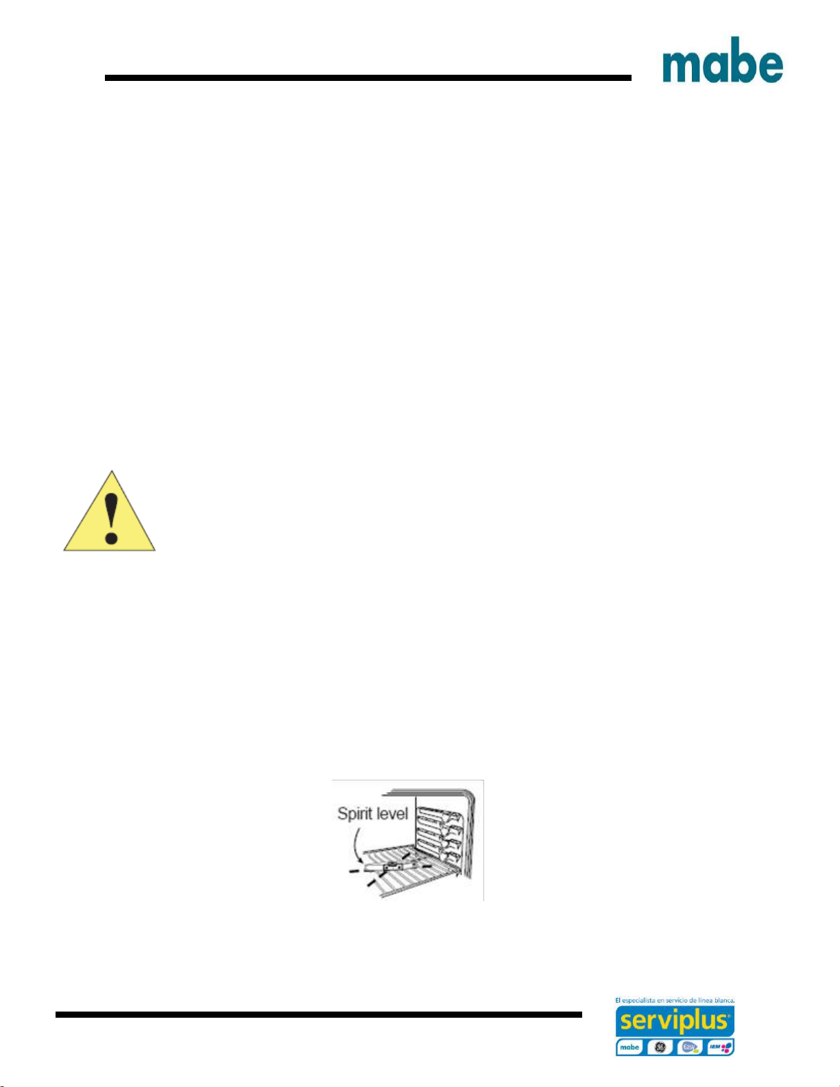
B. Check for levelness by placing a spirit or a cup partially filled with water, on one of the oven
racks. Is using a spirit level, take two readings – with the level placed diagonally first in one
direction an then the other.
Page 19
Ingeniería de Servicio
19
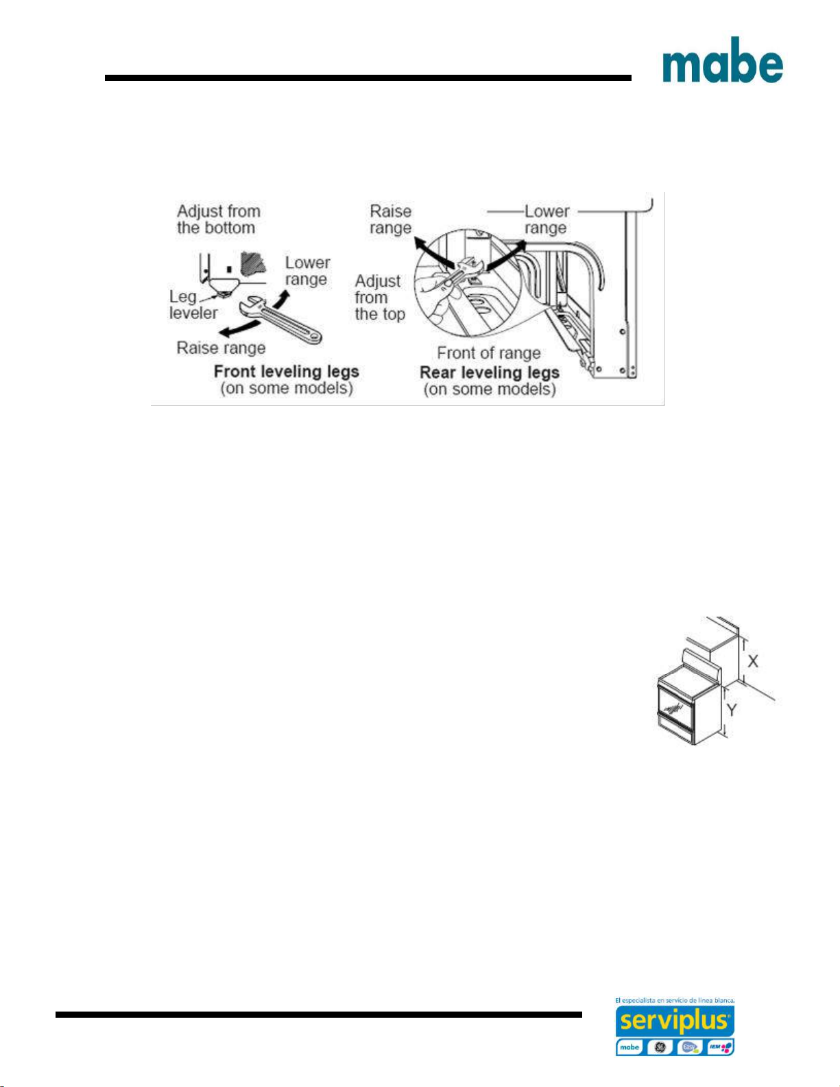
C. Remove storage drawer, broiler drawer or kick panel. The front leveling legs can be asjusted
from the bottom and the rear legs can be adjusted from the top.
.
D. Use an open- end or adjustable wrench to adjust the levelling legs until the range is level.
E. Replace the drawer or panel
F.Plug the range.
G. Measure the height of your countertop at the rear of the openning (X).
H. Adjust two rear leveling legs so that the rear of cooktop is at the same height as the conter (Y).
I. Slide unit into place.
J. Install oven racks in the oven and position the range where it will be installed.
K. Check for levelness by placing a spirit level in one of the oven racks. Take two readings – with
the level placed diagonally first in one dirction and then the other.
L. Adjust front leveling legs until the range is level.
Page 20
Ingeniería de Servicio
20
5.- FINAL INSTALLATION CHECKLIST
• Check to make sure the circuit breaker is closed (RESET) or the circuit fuses are replaced.
• Check to be sure that all packing materials and tape have been removed. This will include tape
on metal panel under control knobs (if applicable), adhesive tape, wire ties, cardboard and
protective plastic. Failure to remove these materials could result in damage to the appliance once
the appliance has been turned on and surfaces have heated.
• Check to make sure that the door and drawer are parallel to each other and that both operate
smoothly. If they do not, see the Owner’s Manual for proper replacement.
• Check to make sure that the rear leveling leg is fully inserted into the Anti-Tip bracket and that
the bracket is securely installed.
OPERATION CHECKLIST
• Turn on one of the top burner unit to observe that the element is turned on within 60 seconds.
Turn off the unit when glare is detected. If the brightness within the time limit is detected, check
the wiring connections. If change is required, having checked the buiding wiring for proper
connections and voltage.
• Make sure the clock (on models so equipped) display is activated. If a series of horizontal red
lines appear on the screen, turn the power off immediately.
Recheck wiring connections. If a range is made to the connections, check again. If no chance is
required, have the building wiring checked for proper connections and voltage.it is recommended
that the clock can be charged if red lines are present
• Make sure all kitchen controls are in the OFF position before leaving the range.
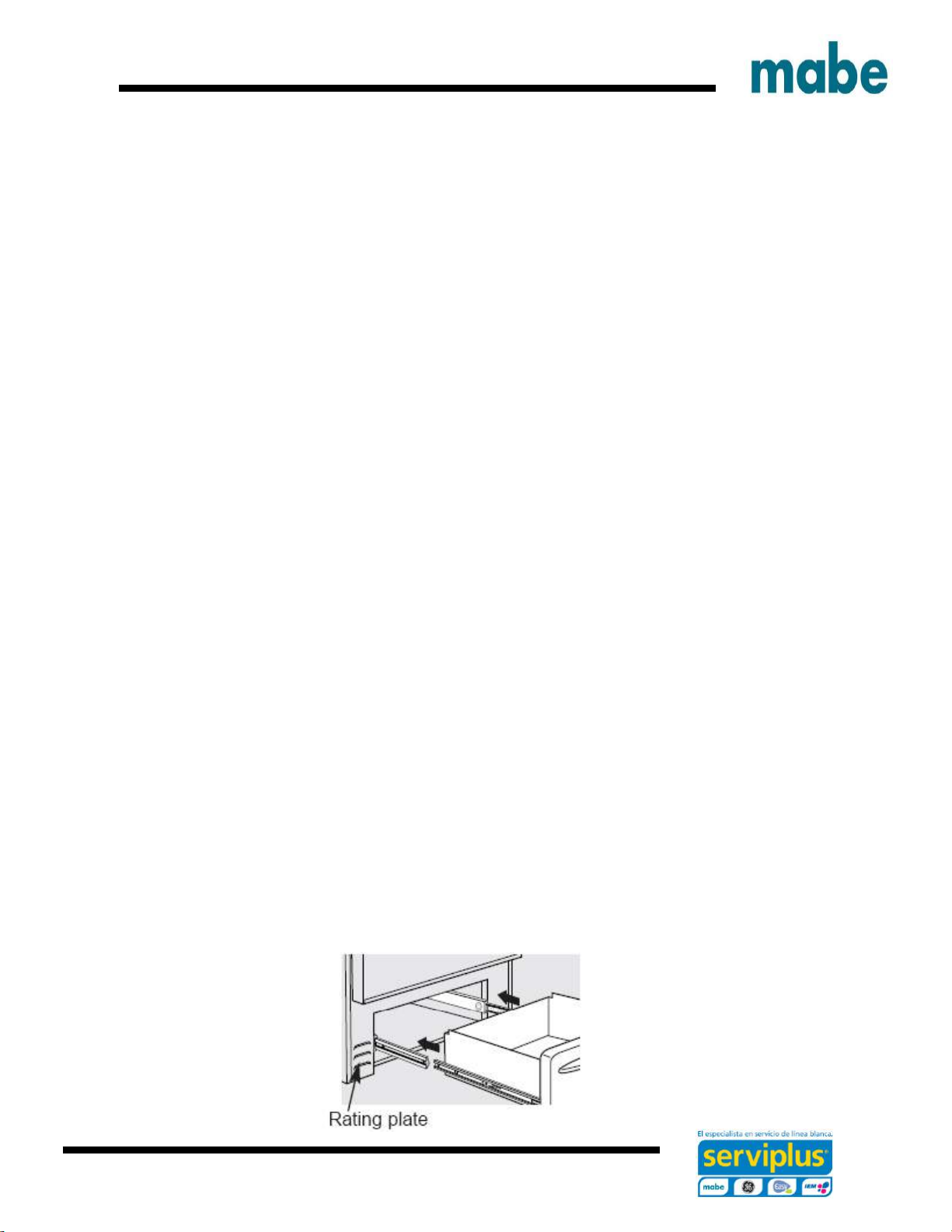
6.- MODEL AND SERIAL NUMBER LOCATION
The plate is located above the drawer under the oven or at the side of the drawer frame.
Page 21
Ingeniería de Servicio
21
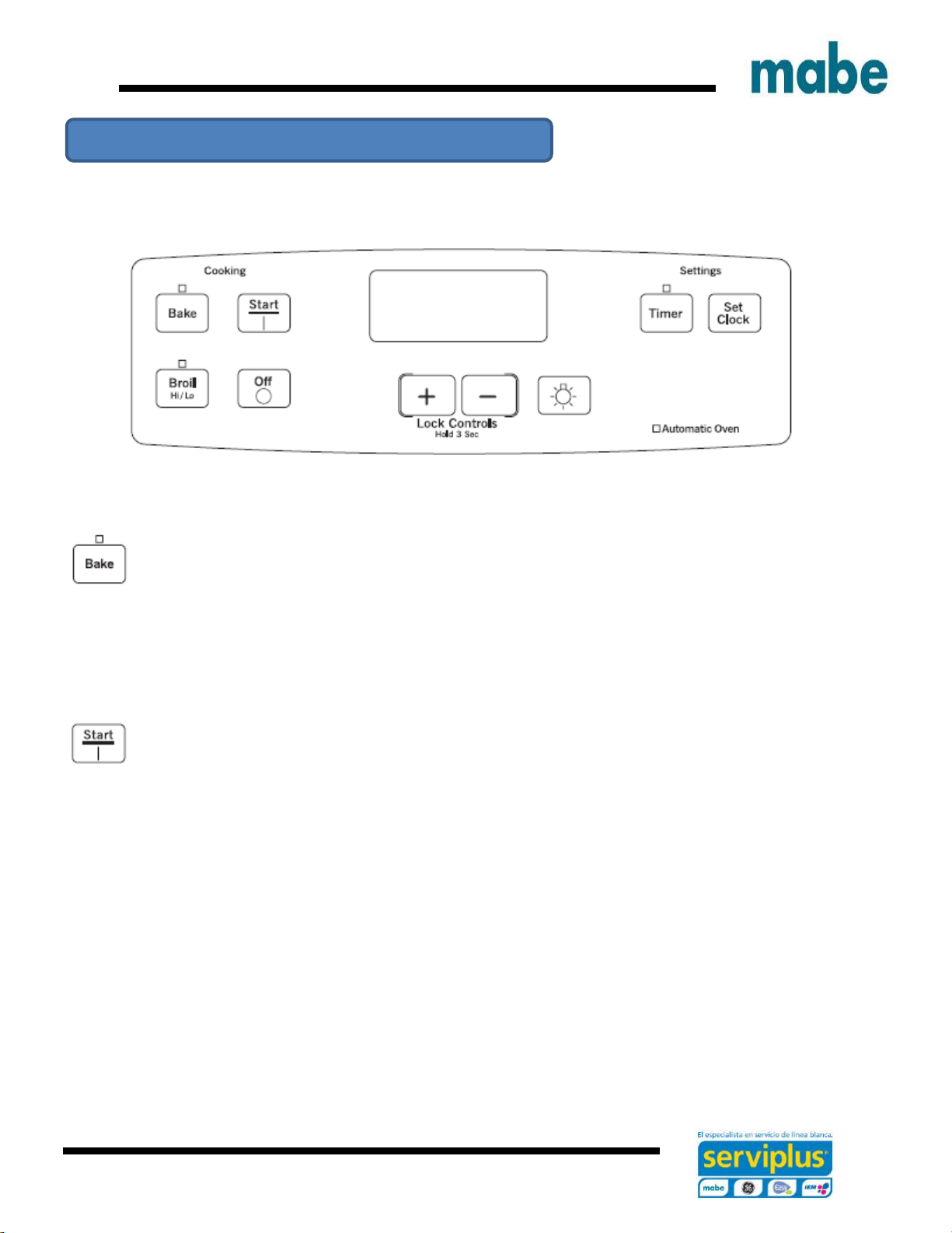
EML27 / JBS27 Models
Throughout this manual, features and appearance may vary from your model.
Bake/ Temp Recall Pad
Touch this pad to select the bake function. See the how to set the oven for baking sections.
Bake ligth – Flashes while in edit mode – you can change the oven temperature at this point.
Glows when the oven is on bake mode.
Start pad
Must be touched to start any cooking or cleaniing funtion.
Display
Shows the time of day, oven temperature and the times set for the timer or automatic oven
operations. The display will show Pre while preheating.
If “F –“ and a number or letter flash in the display and the oven control signals, this indicates a
function error code. Refer to the troubleshotting tips section.
Use of control
Page 22
Ingeniería de Servicio
22
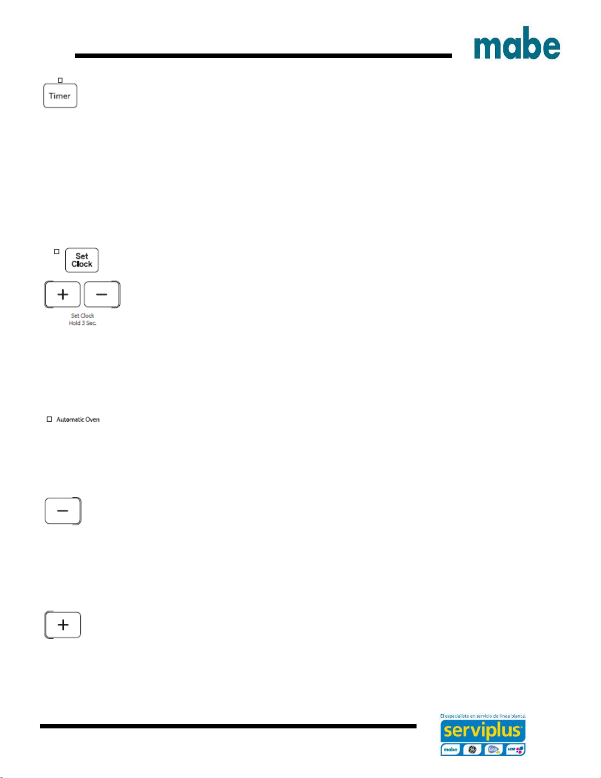
Timer pad
Touch this pad to select the timer feature. Then press + and – pads to adjust time.
Timer light
Flashes while in edit mode – you can change the set time at this point. Glows when the timer has
been activated. Flashes again when the time has run until the control is reset.
Set clock pad
To set the clock, press the clock pad twice or, for models without a clock pad, hold the + and –
pads for 3 seconds. Seee using the clock and timer section on the use and care manual.
Automatic oven light
This lights anytime the oven has been programmed using the cooking time or Star time/Delay star
functions.
- Pad
Short taps to this pad will decrease the time or temperature by small amounts. Touch and hold
the pad to decrease the timer or temperature by larger amounts.
+ Pad
Short taps to this pad will increase the time or temperature by small amounts. Touch and hold the
pad to increase the time or temperature by larger amounts.
Page 23

Ingeniería de Servicio
23
Off pad
Touch this pad to cancel ALL oven operations except the clock and timer.
Broil Hi/Lo Pad
Touch this pad to select the broil functions. See the how to set the oven for broiling section.
Broil ligth
Flashes while in edit mode – you can switch from Hi to Lo Broil at this point. Glows when the oven
is in broil mode.
Page 24

Ingeniería de Servicio
24
EML535 / JCB535 Models
EML735 / JCB735 Models
1. Bake pad
Touch to select the bake function.
2. Broil pad
Touch to select the broil function.
3. Start pad
Must be touched to start any cooking or cleaning function.
4. Display
Shows the time of the day, oven temperature, wheter the oven is in te bake, broil or self – cleaning
mode and the times set for the timer or automatic oven operations.
If “F – and a number or letter” flash in the display and the oven control signals, this indicates a
function error code. Touch the OFF pad. Allow the oven to cool for one hour. Put the oven back
into operation.
Page 25

Ingeniería de Servicio
25
If the oven was set for a timd oven operations an power outage occurred, the clock and all
programmed functions must be reset.
The time of day will flash in the display when there has been a power outage.
5. Self clean pad
Touch to select the self cleaning function.
6. Light pad.
Touch to turn the oven light on or off.
7. Start time pad
Use along with COOK TIME or CLEAN pads to set the oven to start and stop automatically at a
time its has been set.
8. Cook time pad
Touch and touch the number pads to set the amount of time you want your food to cook. The
oven will shut oof when the cooking time has run out.
9. Off pad
Touch to cancel All oven operations except the clock and timer.
10. Clock pad
Touch before setting the clock.
11. Number pads
Use to set any function requiring numbers such as the time of day on the clock, the timer, the
oven temperature, the internal food temperature, the start time and length of operation for timed
baking and self cleaning or setting the clock.
Page 26

Ingeniería de Servicio
26
12. Timer pad
Touch to select the timer feature.
EML835 / JCB835 Models
1. Bake pad
Touch to select the bake function.
2. Broil pad
Touch to select the broil function.
3. Warm pad
Touch to select the warm oven function.
4. Start pad
Must be touched to start any cooking or cleaning function.
5. Display
Page 27

Ingeniería de Servicio
27
Shows the time of the day, oven temperature, wheter the oven is in te bake, broil or self – cleaning
mode and the times set for the timer or automatic oven operations.
If “F – and a number or letter” flash in the display and the oven control signals, this indicates a
function error code. Touch the OFF pad. Allow the oven to cool for one hour. Put the oven back
into operation.
If the oven was set for a timd oven operations an power outage occurred, the clock and all
programmed functions must be reset.
The time of day will flash in the display when there has been a power outage.
6. Clean pad
The oven has two cleaning models: Self clean and Steam clean.
7. Light pad.
Touch to turn the oven light on or off.
8. Start time pad
Use along with COOK TIME or CLEAN pads to set the oven to start and stop automatically at a
time its has been set.
9. Cook time pad
Touch and touch the number pads to set the amount of time you want your food to cook. The
oven will shut oof when the cooking time has run out.
10. Off pad
Touch to cancel All oven operations except the clock and timer.
11. Clock pad
Touch before setting the clock.
Page 28

Ingeniería de Servicio
28
12. Number pads
Use to set any function requiring numbers such as the time of day on the clock, the timer, the
oven temperature, the internal food temperature, the start time and length of operation for timed
baking and self cleaning or setting the clock.
13. Timer pad
Touch to select the timer feature.
Warming zone
Tocuh to keep hot cooked food hot.
Using the oven
To avoid possible burns, place the racks in the desired position before turning on the oven.
Before you start...
The racks have stops, so that when placed correctly on the supports, they will stop before coming
completely out and will not tilt.
When placing and removing cookware, pull the rack out until it stops.
On some models, the bake heating element is under the oven floor. Do not place foods on the
oven bottom for cooking.
To remove a rack, pull it toward you, tilt the front end up and pull it out.
To replace, place the end of the rack (stop-locks) on the support, tilt up the front and push the
rack in.
Page 29

Ingeniería de Servicio
29
The oven has 6 racks positions. It also has a special rack position ( R ) for oversized items such
as a large turkey.
CAUTION
When you are using a rack in the lowest position (A), you will need to use caution when pulling
the rack out.
We recommend that you pull the rack out several inches and then, using two pot holders, pull the
rack out by holding the sides of it. The rack is low and you could be burned if you place your hand
in the middle of the rack and pull all the way out. Be very careful not to burn your hand on the
door when using the rack in the lowest position (A).
Aluminum foil
Do not use aluminum foil on the bottom of the oven.
Never entirely cover a rack with aluminum foil. This will disturb the heat circulation and result in
poor baking.
A smaller sheet of foil may be used to catch a spillover by placing it on a lower rack several inches
below the food.
How to set the oven for Baking or Roasting
1. Touch the BAKE pad.
2. Touch the number pads or the “ + “ and “ – “ pads until the desired temperature is displayed.
Page 30

Ingeniería de Servicio
30
3. Touch the START pad.
The oven will start automatically.
When the oven reaches the selected temperature, the oven control will beep several times and
the display will show the oven temperature.
NOTE: You will hear the convection fan (on some models) while the oven is preheating. The fan
will stop after the oven is preheated and the display shows your set temperature. This is normal.
To change the oven temperature during the BAKE cycle, touch the BAKE pad and then the
number pads to get the new temperature.
4. Check food doneness at the minimum time on the recipe. Cook longer if necessary.
5. Press the CLEAR / OFF pad once cooking is complete, and then remove the food from the
oven.
How to set the oven for broil
Use LO Broil to cook foods such as poultry or thick cuts of meat thoroughly without overbrowning
them.
1.- Place the meat or fish on a broiler grid in a broiler pan designed for broiling.
2.- Follow suggested rack position in the broiling guide.
3.- Touch the pad BROIL HI / LO once for HI broil to change to LO broil, touch the pad again.
4.- Touch the START pad.
5.- When broiling finished, touch the CLEAR / OFF pad.
Door is not provided with a broil position.
Page 31

Ingeniería de Servicio
31
Broiling guide
The size, weight, thickness, starting temperature and your preference of doneness will affect
broiling times. This guide is based on meats at refrigerator temperature.
Preheat the broiler for 2 minutes to improve performance.
* Use rack position A for the smaller, 2-Rack position oven.
Page 32

Ingeniería de Servicio
32
Using the timed baking and roasting features (on some models)
NOTE: Foods that spoil easily such as milk, eggs, fish, stuffings and poultry should not be allowed
to sit for more than 1 hour before or after cooking. Room temperature promotes the growth of
harmful bacteria.
Be sure that the oven light is off because heat from the bulb will speed harmful bacteria growth.
How to Set an Immediate Start and Automatic Stop
The oven will turn on immediately and cook for a selected length of time. At the end of the cooking
time the oven will turn off automatically.
1. Touch the BAKE pad.
2. Touch the number pads to set the desired oven temperature.
3. Touch the COOK TIME pad.
NOTE: If your recipe requires preheating, you may need to add additional time to the length of
the cooking time.
4. Touch the number pads to set the desired length of cooking time. The minimum cooking time
you can set is 1 minute.
The oven temperature that you set and the cooking time that you entered will be in the display.
5. Touch the START pad.
Page 33

Ingeniería de Servicio
33
NOTE: An attention tone will sound if you are using timed baking and do not touch the START
pad.
The oven will turn ON, and the display will show the cooking time countdown and the changing
temperature starting at 37.8°C (100°F). (The temperature display will start to change once the
oven temperature reaches 37.8°C [100°F].) When the oven reaches the temperature you set, 3
beeps will sound.
The oven will continue to cook for the set amount of time, then turn off automatically, unless the
WARM feature was set. See the How to Set the Upper Oven for Warming section..
6.- Touch the CLEAR/OFF pad to clear the display if necessary. Remove the food from the oven.
Remember, even though the oven turns off automatically, food left in the oven will continue
cooking after the oven turns off.
How to Set a Delayed Start and Automatic Stop
The oven will turn on at the time of day you set, cook for a specific length of time and then turn
off automatically.
Make sure the clock shows the correct time of day.
1. Touch the BAKE pad.
2. Touch the number pads to set the desired oven temperature.
Page 34

Ingeniería de Servicio
34
3. Touch the COOK TIME pad.
NOTE: If your recipe requirew preheating, you may need to add additional time to the lengh of
the cooking time.
4.- Touch the number pads to set the desired length of cooking time. The minimum cooking time
you can set is 1 minute.
The oven temperature that you set and the cooking time that you entered will be shown in the
display.
5.- Touch the DELAY START pad.
6.- Touch the number pads to set the time of day you want the oven to turn on and start cooking.
7.- Touch START pad.
NOTE: An attention tone will sound if you are using timed baking and do not touch the start pad.
NOTE: If you would like to check the times you have set, touch the DELAY START pad to check
the start time you have set or touch the COOK TIME pad to check the length of cooking time you
have set.
When the oven turns ON at the time of day you set, the display will show the cooking time
countdown and the changing temperature starting at 37.8°C (100°F). (The temperature display
will start to change once the oven temperature reaches 37.8°C [100°F].) When the oven reaches
the temperature you set, beeps will sound.
The oven will continue to cook for the set amount of time, then turn off automatically.
8.- Touch the CLEAR/OFF pad to clear the display if necessary. Remove the food from the oven.
Remember, even though the oven turns off automatically, food left in the oven will continue
cooking after the oven turns off.
Page 35

Ingeniería de Servicio
35
Using the kitchen timer.
(On some models)
The kitchen timer is in hours and minutes.
The kitchen timer does not control oven operations. The maximum adjustment in the kitchen timer
is 9 hours and 59 minutes.
To set the kitchen timer
1.- Press the TIMER pad.
2.- Press the number buttons until the amount of time you want appears on the display. For
example to set 2 hours and 45 minutes, touch 2, 4 and 5 in that order, if you make a mistake,
pres the TIMER pad and start again.
3.- Touch START pad.
After touching the START pad, SET disappears; this tells you the time is counting down, although
the display does not change until one minute has passed.
Seconds will not be shown in the display until the last minute is countinf down.
4.- When the kitchen timer reaches :00, the control will beep 3 times followed by one beep every
6 seconds until the TIMER pad is touched.
The 6-second tone can be cancelled by following the steps in the Special features of your oven
control section under Tones at the End of a Timed Cycle.
To reset the kitchen timer
If the display is still showing the time remaining, you may change it by touching the TIMER pad
then touch the number pads until the time you want appears in the display.
If the remaining time is not in the display (clock, delay start or cooking time are in the display),
recall the remaining time by touching the TIMER pad and then touching the number pads to enter
the new time you want.
To cancel the timer
Page 36

Ingeniería de Servicio
36
Touch the TIMER pad twice or touch TIMER.
Adjust the oven thermostat
You may find that your new oven cooks differently than the one it replaced. Use your new oven
for a few weeks to become more familiar with it. If you still think your new oven is too hot or too
cold, you can adjust the thermostat yourself.
Do not use thermometers, such as those found in grocery stores, to check the temperature setting
of your oven.
These thermometers may vary 20–40 degrees.
NOTE: This adjustment will only affect baking and roasting temperatures; it will not affect broiling
or self-cleaning temperatures. The adjustment will be retained in memory after a power failure.
(On some models)
To adjust the thermostat
1. Touch the BAKE and BROIL pads at the same time for 3 seconds until the display shows SF.
2. Touch the BAKE pad. A two digit number shows in the display.
Touch BAKE again to alternate between increasing and decreasing the oven temperature.
Page 37

Ingeniería de Servicio
37
3. The oven temperature can be adjusted up to (+) 19°C (35°F) cooler. Touch the number pads
the same way you read them. For example, to change the oven temperature 12°C (15°F), touch
1 and 5.
4. When you have made the adjustment, touch the START pad to go back to the time of day
display. Use your oven as you would normally.
Using the concection oven. (On some models)
How to set the oven for convection Baking or Roasting
1. Touch the CONVECTION BAKE pad once for multi.rack convection baking. This mode is used
for cooking food items on more than one rack (i.e 2,3 or more racks) at the same time in
convection bake. Touch the CONVECTION BAKE pad twice for one-rack convection baking
this mode is used for cooking food items on only one rack in convection bake. Touch the
CONVECTION ROAST pad for convection roasting (on some models)
2. Touch the number pads to set the oven temperature.
3. Touch the start pad.
NOTE: If the auto recipe conversion feature is on, it will automatically reduce the set regular
baking temperature by 13,9°C (25°F) to the appropiate convection temperature in convection
bake mode.
To change the oven temperature, touch the CONVECTION BAKE or CONVECTION ROAST pas
to ser the new temperature.
When the oven starts to heat, the changing temperature, starting at 37,8°C (100°F), will be
displayed. When oven reches the temperature you set, 3 beeps will sound.
4. Touch OFF pad when finished.
Page 38

Ingeniería de Servicio
38
A clicking sound during baking is normal.
In convection bake modes, for maximum cooking evenness, the fan is designed to rotate in both
directions, with a pause in between, this is normal.
Convection fan opetation
In a convection oven, a fan circulates hot air over, under and around food.
This hot circulation is distributed evenly throughout the oven cavity.
As a result, the food is cooked evenly and browned – often in less time with convection heat.
NOTE: To maximize cooking evenness, the fan is designed to rotate in both directions, with a
pause in between. This is normal.
The convection fan shuts off when the oven door is opened. DO NOT leave the door open for
long periods of time while using convection cooking or you may shorten the life of the convection
heating element.
Multi-Rack convection baking
Because heated air is circulated evenly throughout the oven, foods can be baked with excellent
results using multiple racks.
Multi-rack baking may increase cook times slightly for some foods but the overall result is time
saved. Cookies, muffins, biscuits and other quick breads give very good results with multi-rack
baking.
Page 39

Ingeniería de Servicio
39
When baking on 3 racks, place one rack in the second (B) position, another rack in the fourth (D)
position and the third rack in the sixth (F) position.
For two-rack baking, place one rack in the second (B) rack position. Place the other rack in the
fifth (E) rack position.
Using the self clean oven.
Wipe up heavy soil on the oven bottom.
Gently wipe off glass inner door with hot, soapy water and a sponge or soft cloth. Never use fiber,
abrasive cleaners or ammonia based products.
Page 40

Ingeniería de Servicio
40
Before a clean Cycle
Warning
FIRE HAZARD: Wipe grease and heavy soil from the oven bottom before self cleaning. Failure to
do so may result in an oven fire.
We recommend venting your kitchen with an open window or using a ventilation fan or hood
during the first self-clean cycle.
Remove any broiler pan, broiler grid, probe, all cookware and any aluminum foil from the oven.
NOTE: If your oven is equipped with shiny, silver-colored oven racks, remove them before you
begin the self-clean cycle.
The shiny, silver-colored oven racks (on some models) can be self-cleaned, but they will darken,
lose their luster and become hard to slide.
If your oven is equipped with gray porcelain-coated oven racks, they may be left in the oven during
the self-clean cycle.
Soil on the front frame of the range and outside the gasket on the door will need to be cleaned by
hand. Clean these areas with hot water, soap-filled steel-wool pads or cleansers such as Soft
Scrub . Rinse well with clean water and dry.
Do not clean the gasket. The fiberglass material of the oven door gasket cannot withstand
abrasion. It is essential for the gasket to remain intact. If you notice it becoming worn or frayed,
replace it.
Make sure the oven light bulb cover is in place and the oven light is off.
Remove any excessive spillovers in the oven cavity before starting the Self-Cleaning cycle.
To clean use hot, soapy water and a cloth. Large spillovers can use heavy smoke or fire when
subjected to high temperatures.
DO NOT allow food spills with a high sugar or acid content (such as milk, tomatoes, sauerkraut,
fruit, juices or pie filling) to remain on the surface as they may leave a dull spot even after cleaning.
Page 41

Ingeniería de Servicio
41
How to set the oven for Cleaning
The oven doors must be closed and all controls set correctly for the cycle to work properly.
1.- Touch SELF CLEAN pad.
A 3-hour self-clean time is recommended for use when cleaning small, contained spills. A self-
clean time of 5 hours is recommended for a dirtier oven..
2.- If a time other than 5 hours or 3 hours is needed, use the number pads and enter the desired
clean time.
You can change the clean time to any time between 3 hours and 5 hours, depending on how dirty
your oven is
3.- Press the START pad.
The oven door locks automatically. The cooktop elements are also locked out during self-clean.
The display will show the clean time remaining.
It will not be possible to open the oven doors or use the cooktop until the temperature drops below
the lock temperature and LOCKED/DOOR goes off in the control display.
When LOCKED/DOOR goes off, you will be able to open the doors.
• The word LOCKED/DOOR will flash and the word door will display if you set the clean cycle
and forget to close the oven doors.
• To stop a clean cycle, touch the OFF pad. When LOCKED/DOOR goes off, indicating the
ovens have cooled below the locking temperature, you will be able to open the doors.
• When the oven is set to self-clean, oven will lock and the cooktop controls will lock out.
The oven and cooktop cannot be used when it is set to self-clean.
Page 42

Ingeniería de Servicio
42
After a clean cycle
You may notice some white ash in the oven. Wipe it up with a damp cloth after the oven cools.
If white spots remain, remove them with a soap-filled steel wool pad and rinse thoroughly with a
vinegar and water mixture.
These deposits are usually a salt residue that cannot be removed by the clean cycle.
If the oven is not clean after one clean cycle, repeat the cycle.
You cannot set the oven for cooking or another self-clean cycle until the oven is cool enough for
the door to unlock.
While the oven is self-cleaning, you can touch the CLOCK pad to display the time of day. To
return to the clean countdown, touch the SELF CLEAN pad.
If the racks become hard to slide, apply a small amount of cooking oil to a paper towel and wipe
the edges of the oven racks with the paper towel..
Using Steam clean
CAUTION: During steam clean cycle the oven bottom becomes hot enough to cause burns. Wait
until the cycle is over (25 minutes) before wiping the inside surfaces of the oven, failure to do so
may result in burns.
The steam clean cycle makes it easier to clean light soiling off the porcelain oven interior.
The range should be at room temperature before beginning the steam clean cycle. If the oven is
too “hot” sill appear on the display and the cycle will not activate until the oven cools down.
The steam clean cycle performs best on new spills or soils. Burned- on food is more difficult to
remove.
Page 43

Ingeniería de Servicio
43
To begin steam clean cycle:
1. Remove the racks and accessories from the oven cavity. Do not replace cookware or othet
items in the oven during the steam clean cycle.
2. Pour a cup (8 oz) room temperature water onto the recessed area of the oven bottom. Do not
add cleannig solutions or chemicals of any kind to the water.
3. Close the door.
4. Activate the STEAM CLEAN function by pressing the STEAM CLEAN pad, then press START
pad.
5. A 25 minute cycle will begin to count down on the display.
6. When steam clen cycle is complete, the oven control will beep and the door will be unlatched.
Press OFF pad and open the door.
7. The oven bottom and ramaining water will still be warm at the end of the cycle. This is normal.
8. Remove soils using a scrub brush or nylon scouring pad. A soap-filled steel wool pad may be
used only on the porcelain oven interior. The use of abrasive pads will scratch the door glass.
Do not wipe soil or water onto the door gasket.
9. Remove any ramaining water with a dry cloth or sponge.
10. Leave the door open to air dry. Press the OFF pad at any time to end te cycle.
Page 44

Ingeniería de Servicio
44
Backguard
Infinite switches
Knobs
Cooktop
Surface elements
Oven door
Fan
Oven heating element
Oven sensor
Socket
Lamp
List of main components
Page 45

Ingeniería de Servicio
45
Disassemble and retrofit
Power cord
To install the power cord, remove the
cover element located at the back of
the appliance.
A) Remove the ¼” screws with a box
screwdriver.
B) Lift the lid and slide it to the left to
release the flanges support.
Componente view
Insert the power cord through the hole in
the base and using a box screwdriver,
remove the ¼” screws to place the power
cord.
Page 46

Ingeniería de Servicio
46
Insert the power cord through the hole in the base and
using a box screwdriver, remove the ¼” screws to place
the power cord
Power cord
Place the terminal according to the poka yoke system
and secure with screws.
A
B R V
Place the back cover
Page 47

Ingeniería de Servicio
47
Backguard
To remove the control panel is necessary
to remove the screws locatedin the lower
with a Torx T 15
2.- Remove the ¼” screws from the back.
3.- Pull the control panel upwards to release from the flanges support.
Components view.
Page 48

Ingeniería de Servicio
48
Knobs
To remove, take the knobs from the sides and
carefully pull to completely remove the knob.
Knob in good condition
To replace the knobs, take them form the sides and
carefully push until stop position
Page 49

Ingeniería de Servicio
49
Remove the ¼” screw in order to remove the back
cover and access the infinite swiches without the need
to completely remove the backguard.
Infinite switch
Component view
Remove the knob carefully. Remove the Phillips screws.
With support from the nose pliers, remove the
pads one by one
Page 50

Ingeniería de Servicio
50
CAUTION. Do not manipulate
the switch blade since this may
decalibrate and generate an
equipment malfunction
With support from the nose pliers place back the
pads, one by one.
Page 51

Ingeniería de Servicio
51
Cooktop
To remove the cooktop remove the ¼” screws using the box screwdriver located at the bottom of
the front corners of the rangetop
To remove the cooktop, lift it gently until its axes don’t touch the guides
Note: Before removing the cover, disconnect all electrical terminals.
Page 52

Ingeniería de Servicio
52
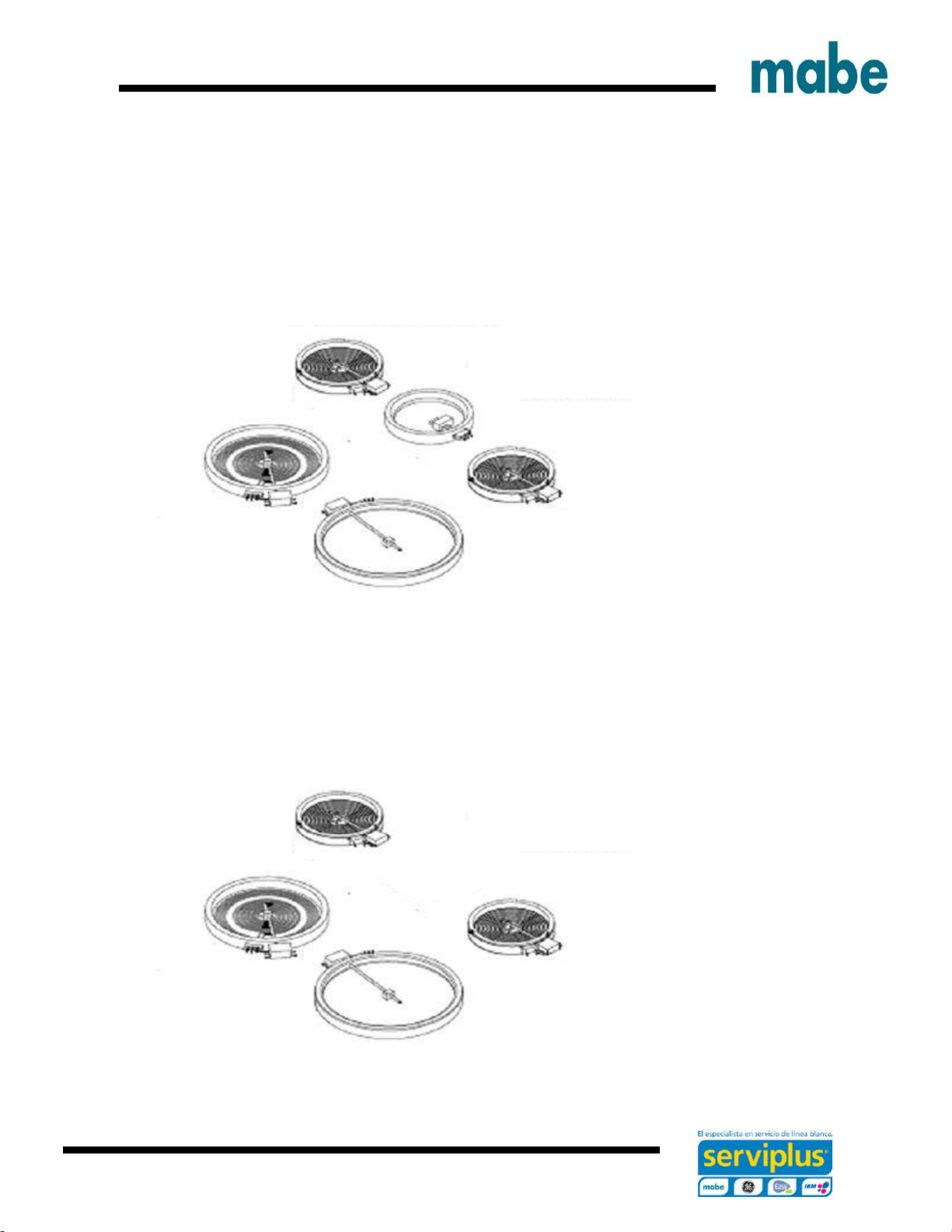
Surface elements
To gain Access to the cooking resistances is necessary to remove the ¼” screws located at the
bottom of the front corners.
Components view.
Page 53

Ingeniería de Servicio
53
Remove the Surface clips from the bottom using a flat screw driver.
Top heating element and sensor view.
CAUTION: Be careful when handling the component terminals and
verify these connections are made according to the wiring diagrams
attached.
Page 54

Ingeniería de Servicio
54
To remove the coil surface burners, lift and pull carefully until the part is
removed completely.
Page 55

Ingeniería de Servicio
55
Door
2
2.- Lift the door almost to the point of closure.
3.- Remove the door from its position.
3
1.- To remove the door, first lift the safety pins.
1
Page 56

Ingeniería de Servicio
56
Remove the brake pads using nose pliers, taking care
not to damage them
Oven door latch
To Access the door latch, remove the screws and
lift the cover.
Page 57

Ingeniería de Servicio
57
To remove the door latch is necessary to remove the screws using a Torx T-15
Door sensor. Remove the connections using a flat screwdriver press safety
pins and push to remove the sensor.
Oven door sensor
Page 58

Ingeniería de Servicio
58
Using nose pliers, remove the brake pads
from the resistor terminals
Oven sensor
Note: To chance the oven sensor, remove the back cover of the appliance.
Remove the ¼” screws .
Disconnect and remove the sensor.
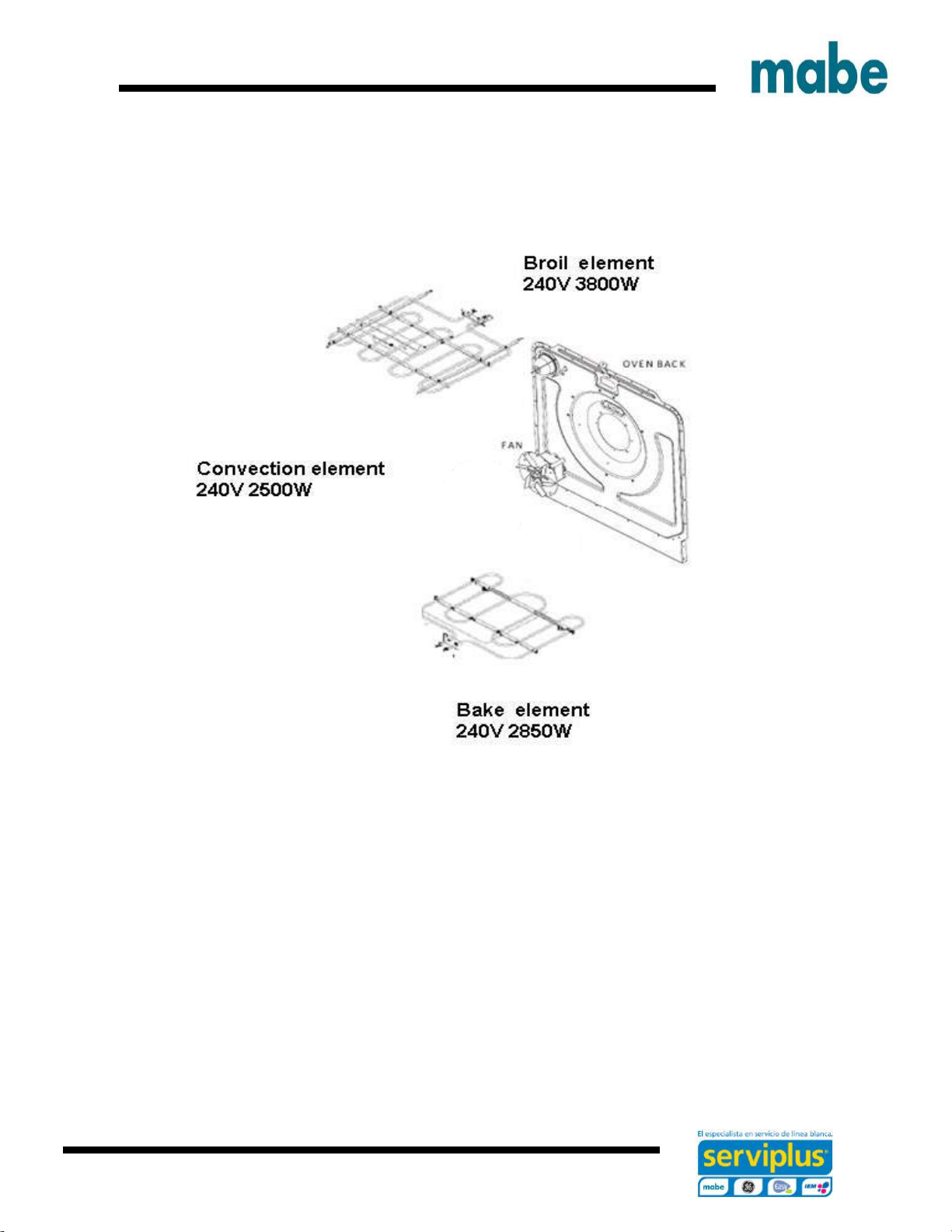
Oven heating elements
To replace the oven heating element it is necessary to remove the back cover of the appliance.
Using screwdriver, remove the box screws ¼” and
remove the resistance.
Page 59

Ingeniería de Servicio
59
Fan
Remove the screws fron the fan guard using a Phillips screwdriver.
Remove the screws holding the fan being careful do not drop it abruptly
Page 60

Ingeniería de Servicio
60
Disconnect the fan being careful not to drop its power cord, otherwise you will
have to remove the back cover.
Page 61

Ingeniería de Servicio
61
To change the lamp of the range
push the lamp protector safety to
one side.
Lamp, lamp protector and socket
Remove the protector carefully so as not to
break it.
To change the socket, remove the back cover of the appliance
Using a ¼” box screwdriver, remove the
screws.
Using nose pliers remove the brake pads. To
remove the socket press the safety pins and
push.
Page 62

Ingeniería de Servicio
62
Electric diagrams
Schematic diagram EML27/JBS27 models
Page 63

Ingeniería de Servicio
63
Schematic diagram EML535 / JCB535 models
Page 64

Ingeniería de Servicio
64
Schematic diagram EML735 / JCB735 models
Page 65

Ingeniería de Servicio
65
Schematic diagram EML835 / JCB835 models
Page 66

Ingeniería de Servicio
66
The electronic control array for the oven system consists of:
Control, key panel, oven sensor, assembly for the door lacth and convection fan.
KEY PANEL TEST
1. Touch each pad on the Key Panel.
2. If the Key Panel is functioning properly, the following should occur:
• Bake, Broil, Convection Bake, Convection Roast, Clean, Timer, Clock, Stop Time and Cook
Time Modes – An audible tone sounds and the display shows the mode of the operation selected.
• Clear/Off – An audible tone sounds and the display shows the time of day.
• Number pads can only be used after another function has been selected.
To display fault codes in the memory simultaneously press and hold COOKING TIME and DELAY
START pads and then press number 9 pad..
Page 67

Ingeniería de Servicio
67
PROBLEM
POSSIBLE CAUSES
WHAT TO DO
Surface units will not
maintain a rolling boil or
cooking is not fast
enough
Improper cookware being
used.
Use pans which are flat and match the
diameter of the surface unit selected.
In some areas, the power
(voltage) may be low.
Cover pan with a lid until desired heat is
obtained.
Surface units do not work
properly
A fuse in your home may
be blown or the circuit
breaker tripped.
Replace the fuse or reset the circuit
breaker.
Cooktop controls
improperly set.
Check to see the correct control is set
for the surface unit you are using.
Surface unit stops
glowing when turned to a
lower setting
This is normal. The unit is still on and hot.
Scratches (may appear
as cracks) on cooktop
glass surface
Incorrect cleaning
methods being used.
Scratches are not removable. Tiny
scratches will become less visible in
time as a result of cleaning.
Cookware with rough
bottoms being used or
coarse particles (salt or
sand) were between the
cookware and the surface
of the cooktop.
To avoid scratches, use the
recommended cleaning procedures.
Make sure bottoms of cookware are
clean before use, and use cookware
with smooth bottoms.
Cookware has been slid across the cooktop surface.
Areas of discoloration on
the cooktop
Food spillovers not
cleaned before next use.
See the Cleaning the glass cooktop
section.
Failures and solutions
Page 68

Ingeniería de Servicio
68
Hot surface on a model
with a light-colored
cooktop.
This is normal. The surface may appear
discolored when it is hot. This is
temporary and will disappear as the
glass cools.
Plastic melted to the
surface
Hot cooktop came into
contact with plastic placed
on the hot cooktop.
See the Glass surface potential for
permanent damage
Pitting (or indentation) of
the cooktop
Hot sugar mixture spilled
on the cooktop.
Call a qualified technician for
replacement.
Frequent cycling off and
on of surface units
Improper cookware being
used.
Use only flat cookware to minimize
cycling.
Oven light does not work
Light bulb is loose.
Tighten or replace the bulb.
Oven will not work
Plug on range is not
completely inserted in the
electrical outlet.
Make sure electrical plug is plugged into
a live, properly grounded outlet.
A fuse in your home may
be blown or the circuit
breaker tripped.
Replace the fuse or reset the circuit
breaker.
Oven controls improperly
set.
See the Using the oven section.
Oven too hot.
Allow the oven to cool to below locking
temperature.
Food does not bake or
roast properly
Oven controls improperly
set.
Make sure you touch the BROIL HI/LO
pad.
Improper rack position
being used.
See the Broiling Guide.
Cookware not suited for
broiling.
For best results, use a pan designed for
broiling.
Page 69

Ingeniería de Servicio
69
The probe is plugged into
the outlet in the oven. (on
some models)
Unplug and remove the probe from the
oven.
In some areas the power
(voltage) may be low.
Preheat the broil element for 10
minutes.
Broil for the longest period of time
recommended in the Broiling Guide.
Oven temperature too hot
or too cold
Oven thermostat needs
adjustment.
See the Adjust the oven thermostat Do
it yourself! section.
Oven door is crooked
The door is out of position.
Because the oven door is removable, it
sometimes gets out of position during
installation. To straighten the door, push
down on the high corner.
Clock and timer do not
work
Plug on range is not
completely inserted in the
electrical outlet.
Make sure electrical plug is plugged into
a live, properly grounded outlet.
A fuse in your home may
be blown or the circuit
breaker tripped.
Replace the fuse or reset the circuit
breaker.
Oven controls improperly
set.
See the Using the clock, kitchen timer
and control lockout section.
Oven will not self-clean
The oven temperature is
too high to set a self-clean
operation.
Allow the range to cool and reset the
controls.
Oven controls improperly
set.
See the Using the self-cleaning oven
section.
The probe is plugged into
the outlet in the oven. (on
some models)
Remove the probe from the oven.
Page 70

Ingeniería de Servicio
70
“Crackling” or “popping”
sound
This is the sound of the
metal heating and cooling
during both the cooking
and cleaning functions.
This is normal.
Excessive smoking
during a clean cycle
Excessive soil.
Touch the CLEAR/OFF pad. Open the
windows to rid the room of smoke. Wait
until LOCKED/DOOR goes off. After the
oven cools, wipe up the excess soil and
reset the clean cycle.
Oven door will not open
after a clean cycle
Oven too hot.
Allow the oven to cool below locking
temperature.
Oven not clean after a
clean cycle
Oven controls not properly
set.
See the Using the self-cleaning upper
and lower ovens section.
Oven was heavily soiled.
Clean up heavy spillovers before
starting the clean cycle. Heavily soiled
ovens may need to self-clean again or
for a longer period of time.
“LOCKED” flashes in the
display
The self-clean cycle has
been selected but the door
is not closed.
Close the oven door.
“LOCKED” is on when
you want to cook
The oven door is locked
because the temperature
inside the oven has not
dropped below the locking
temperature.
Touch the CLEAR/OFF pad. Allow the
oven to cool.
“F” and a number or letter
flash in the display
You have a function error
code.
Disconnect all power to the range for at
least 30 seconds and then reconnect
power. If the function error code
repeats, call for service.
Page 71

Ingeniería de Servicio
71
Range Locked or LOC
On appears in the oven
display or LC appears in
the surface display
The controls have been
locked.
See the Control Lockout section to
unlock.
Control signals after
entering cooking time or
start time
You forgot to enter a bake
temperature or cleaning
time.
Touch the BAKE pad and desired
temperature or the SELF CLEAN pad
and desired clean time.
Display goes blank
A fuse in your home may
be blown or the circuit
breaker tripped.
Replace the fuse or reset the circuit
breaker.
The clock is in the blackout mode.
See the Special features of your oven
control section.
Display flashes
Power failure.
Reset the clock.
Unable to get the display
to show “SF”
Oven control pads were
not touched properly.
The BROIL HI/LO and BAKE pads must
be touched at the same time and held
for 3 seconds.
Power outage, clock
flashes
Power outage or surge.
Reset the clock. If the oven was in use,
you must reset it by touching the
CLEAR/OFF pad, setting the clock and
resetting any cooking function.
Steam from the vent
When using the ovens, it
is normal to see steam
coming out of the oven
vents. As the number of
racks or amount of food
being cooked increases,
the amount of visible
steam will increase.
This is normal.
“Burning” or “oily” odor
emitting from the vent
This is normal in a new
oven and will disappear in
time.
To speed the process, set a self-clean
cycle for a minimum of 3 hours. See the
Using the self-cleaning upper and lower
ovens section.
Page 72

Ingeniería de Servicio
72
Strong odor
An odor from the
insulation around the
inside of the oven is
normal for the first few
times the oven is used.
This is temporary.
Fan noise
A convection fan may
automatically turn on and
off.
This is normal. To maximize cooking
evenness, the fan is designed to
operate in both directions, with a pause
in between.
The convection fan will operate during
preheat of the bake cycle. The fan will
turn off after the oven is heated to the
set temperature. This is normal.
Oven racks are difficult to
slide
The shiny, silver-colored
racks were cleaned in a
self-clean cycle.
Apply a small amount of vegetable oil to
a paper towel and wipe the edges of the
oven racks with the paper towel. Do not
spray with Pam® or other lubricant
sprays.
Drawer does not slide
smoothly or drags
The drawer is out of
alignment.
Fully extend the drawer and push it all
the way in. See the Care and cleaning
of the range section.
Drawer is over-loaded or
load is unbalanced.
Reduce weight. Redistribute drawer
contents.
Food dries out in the
warming drawer
Moisture escaping.
Cover food with lid or aluminum foil.
Drawer not fully closed.
Push drawer in until latch engages.
 Loading...