

Page 1
- 1 -
Service Manual
June-2016
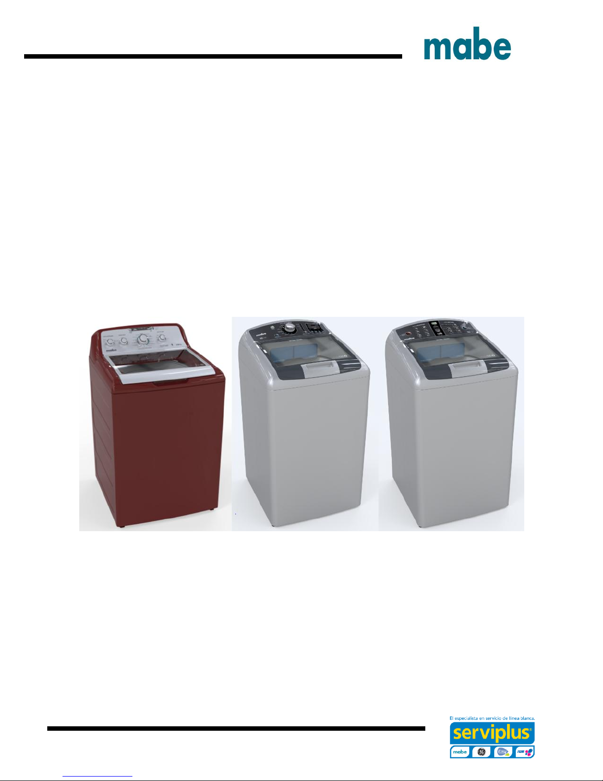
Top Load Washer Kraken 27”
HTW200BMKWW GTW460BMKWW
MTW200BMKWW GTW485BMKWS
GTW220BMKWW GTW680BMKWS
GTW330BMKWW GTW680BMKDG
GTW465BMKWS
Ingeniería de Servicio
Page 2
- 2 -
IMPORTANT SAFETY NOTICE
IMPORTANT SAFETY NOTICE
The information in this presentation is intended for use by individuals
possessing adequate backgrounds of electrical, electronic, & mechanical
experience. Any attempt to repair a major appliance may result in personal
injury & property damage. The manufacturer or seller cannot be
responsible for the interpretation of this information, nor can it assume any
liability in connection with its use.
WARNING
To avoid personal injury, disconnect power before servicing this
product. If electrical power is required for diagnosis or test purposes,
disconnect the power immediately after performing the necessary
checks.
RECONNECT ALL GROUNDING DEVICES
If grounding wires, screws, straps, clips, nuts or washers used to complete
a path to ground are removed for service, they must be returned to their
original position & properly fastened.
Mabe authorized Service Technicians are required to use the Personal
Protection Equipment (PPE) listed below, for your own protection.
Ingeniería de Servicio
Page 3

- 3 -
Dyneema® Cut Resistant Glove
Cut Resistant Sleeve(s)
Steel Toe Work Boot
Brazing Glasses
Plano Type Safety Glasses
Prescription Safety
Glasses
Safety Glasses must be
ANSI Z87.1-2003
compliant
Electrically Rated Glove and
Dyneema® Cut Resistant Glove
Keeper
Ingeniería de Servicio
Page 4
- 4 -
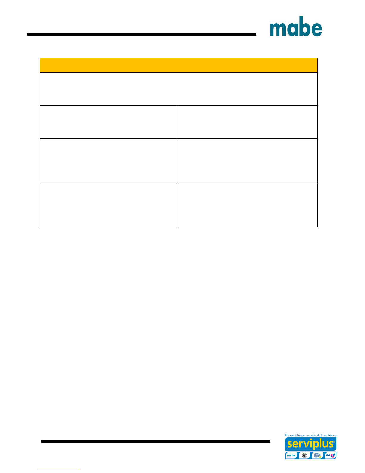
CAUTION
Prior to disassembly of the Washer to access components,
Mabe authorized Service Technicians are REQUIRED to
follow the Lockout / Tagout (LOTO) 6 Step Process
Step 1
Plan and Prepare
Step 4
Apply LOTO device & Lock
Step 2
Shut down the appliance
Step 5
Control (discharge) stored
energy
Step 3
Isolate the appliance
Step 6
“Try It” Verify that the
appliance is locked out
Ingeniería de Servicio
Page 5

- 5 -
Some Features & Benefits
GTW460 Models
Deep Fill: Adds more water for larger
loads.
Dual-Action Agitator: Provide gentle,
dual-wash action.
Deep Rinse: Removes any leftover
soap residue.
Auto Soak: Loosens stains by soaking
up to 2 hours.
Speed Wash: Delivers ready-to-go
results within minutes.
Load Size: Automatically measures
load size, and adjusts settings and
water levels accordingly. Settings are
customizable, so you always get the
wash you want.
GTW680 Models
Sanitize with Oxi: Remove 99.9% of
bacteria with a dedicated cycle that
uses an Oxi additive to boost your
detergents cleaning power while
keeping fabric looking their best.
Stain Removal Guide: Assist removing
tough stains with preprogrammed
settings that modify your cycle to treat
the four most common stains.
Warm Rinse: Just what the consumer
ordered. The option to select between
a warm or cold rinse.
Deep Fill: Adds more water for larger
loads.
Deep Rinse: Removes any leftover
soap residue.
Auto Soak: Loosens stains by soaking
up to 2 hours.
Ingeniería de Servicio
Page 6
- 6 -
T
W
6
8
B
M
K
W
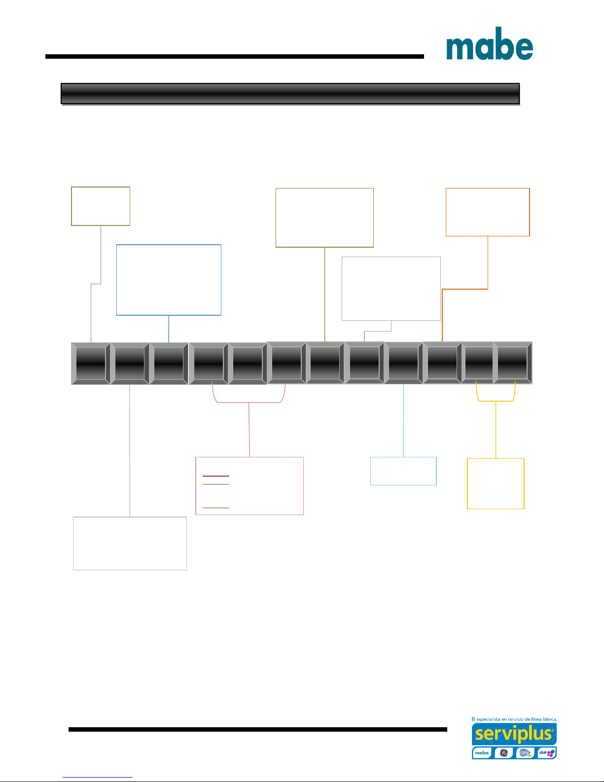
Brand
G = GE
H = Hot Point
M = Moffatt
Configuration:
F = Front Load
T = Top Load – Rear Control
N = Top Load – Front Control
U = Unitized
Platform:
W = Washer
D = Vented Dryer – Std
V = Vented Dryer – Long
C = Condenser Dryer
H = Heat Pump
Z = Flat Back Dryer – Long
X = Flat Back Dryer - Std
Series 1, 2, 3:
Series 1 = 1-9
Series 2 = 1-9
4 = 24” unitized
7 = 27” unitized
Series 3 = 1-9 Washer only
Partner Type
P = Premium Cost (color)
H = Home Depot
L = Lowes
S = Standard
C = Contract (Hoses)
M = Mabe
Year:
K = 2016
Engineering Number
0
1
2
Color:
W
S
0
0
G
S
Product Type
R = Riser
A = 2” Cover Top Load
B = 4” Cover Top Load
S = Standard / Stationary
P = Portable
Nomenclature
The nomenclature breaks down and explains what the letters and numbers mean in the model
number
Seguridad Advertencias y
Ingeniería de Servicio
Page 7
- 7 -
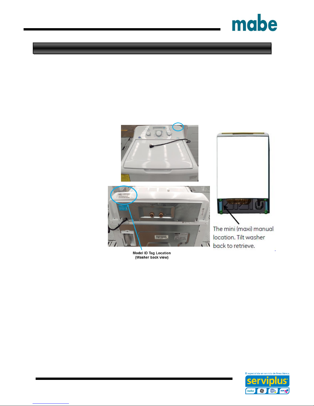
Serial Number and Mini Manual Location
Serial Number
The Serial Number breaks down and explains what the letters and numbers mean in its
structure:
Example of Serial Number: LG312345C
The first two characters of the serial number identify the month and year of manufacture: LG =
June, 2016
A = JAN A = 2013
D = FEB D = 2014
F = MAR F = 2015
G = APR G = 2016
H = MAY H = 2017
L = JUN L = 2018
M = JUL M = 2019
R = AUG R = 2020
S = SEP S = 2021
T = OCT T = 2022
V = NOV V = 2023
Z = DEC Z = 2024
The letter designating the year repeats every 12 years
The third character denotes the product being produced: 3 = Washer (Saltillo, Mexico)
Character 4 thru 8 will denote the number of units built for a given product and will start with
00001 at the beginning of each fiscal month and progress sequentially until 99,999 is
reached or the fiscal month has changed.
Character 9 will denote the Brand and Manufacturing site of final assembly: (Saltillo, Mexico:
C = GE, M = Signature, H = HPT)
The Model Serial ID Tag is located on the right top edge of the backsplash (left top edge from
back view).
The Mini Manual is in a storage bag inside the cabinet at bottom left side.
Ingeniería de Servicio
Page 8

- 8 -
Water Levels
Approximate Minimum Water Levels
Impeller – 7 Gallons or 3 in. depth from
the bottom of the basket.
Agitator – 9 Gallons or 3-3/4 in. depth
from the bottom of the basket.
Test are completed with an empty basket.
Approximate Maximum Water Levels
Impeller – 26 Gallons or 13-1/2 in.
depth from the bottom of the basket.
Press and hold for 3 seconds “Deep
Fill” to achieve.
Impeller “Bulky” setting water level is
25 gallons or 12-3/4 in. depth from the
bottom of the basket.
Agitator – 26 Gallons or 12-1/2 in.
depth from the bottom of the basket.
Set to super.
Ingeniería de Servicio
Page 9
- 9 -
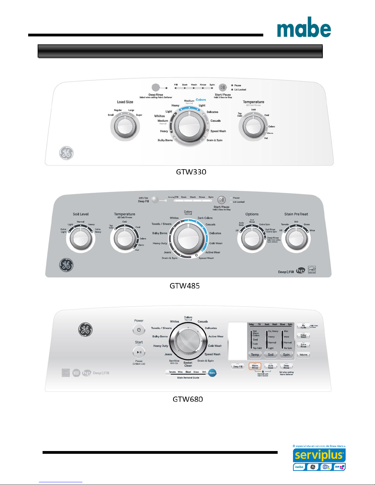
Model Graphics
Ingeniería de Servicio
Page 10
- 10 -
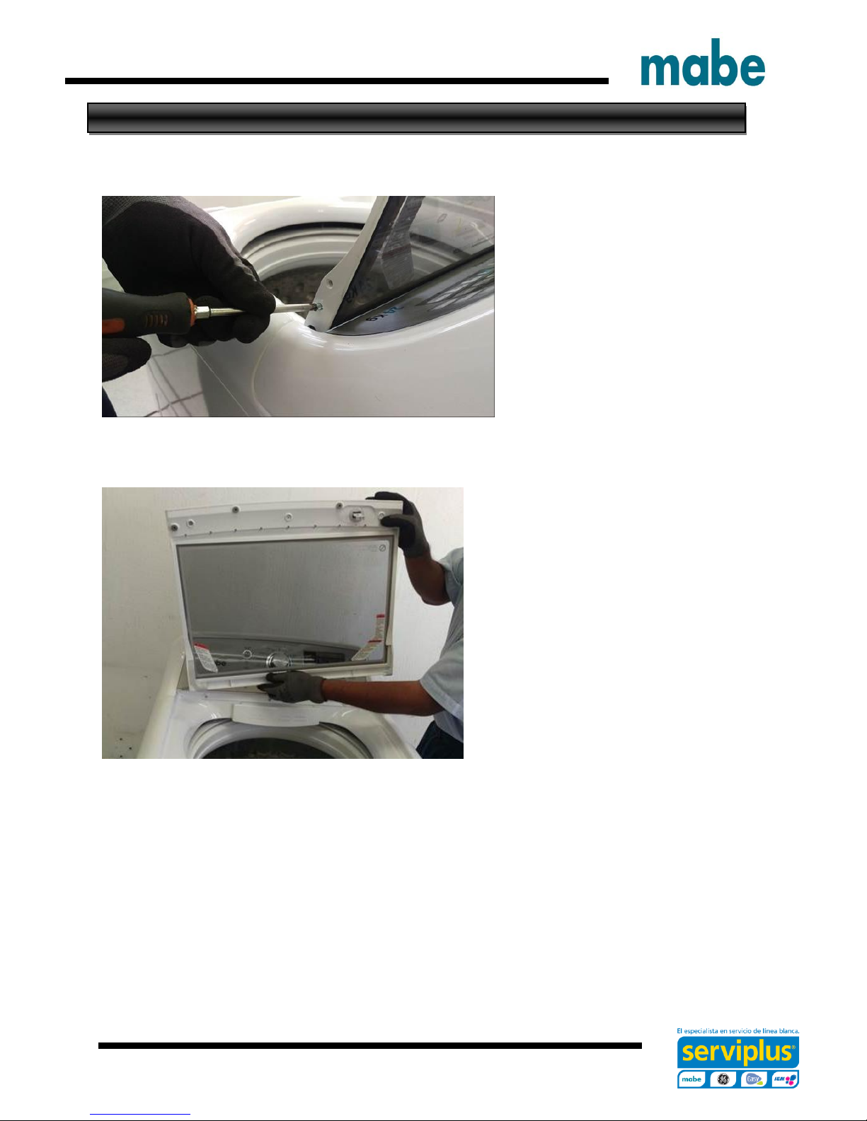
Lid Assembly Removal
Remove the two Philips head
screws of one Hinge (Right or Left
side).
Slide the lid toward the Hinge
Removed and lift it up to remove
Ingeniería de Servicio
Page 11
- 11 -
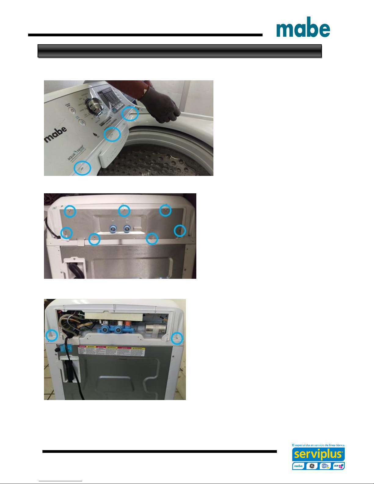
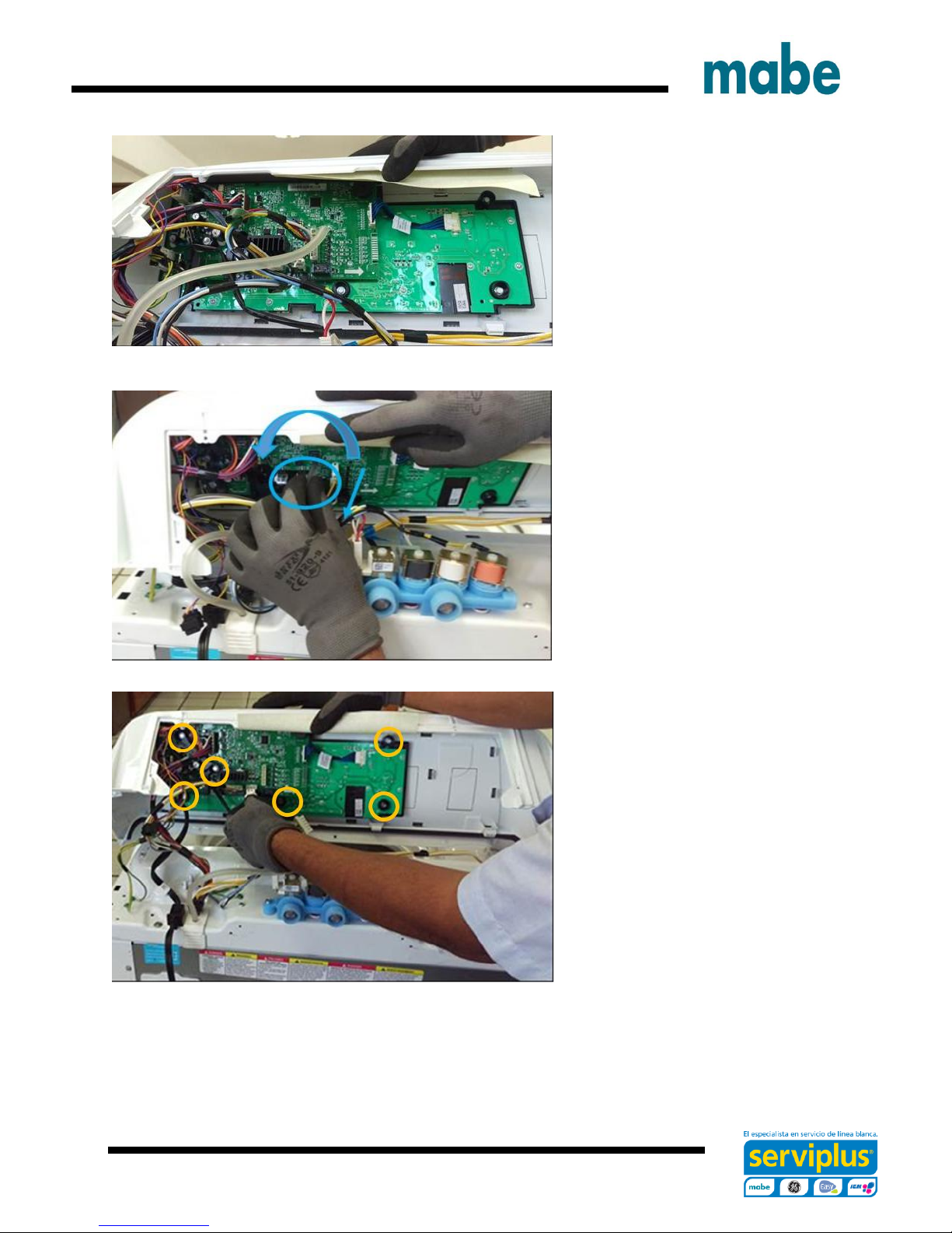
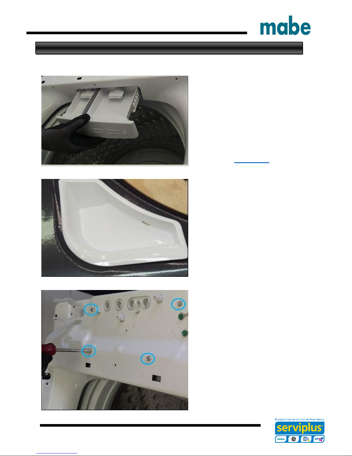
Control Panel Assembly Removal
To remove the control panel assembly, first remove the lid assembly.
Remove the three Philips head
screws that secure the control
panel assembly to the top cover
at front.
Remove the seven ¼ in. hex head
screws from the back panel and
remove it.
Remove the two ¼ in. hex head screws
from the rear corners on the control panel
IMPORTANT.- Do not move the control panel until disengaging the pressure tube from
the control board, otherwise the pressure sensor could be damaged.
Ingeniería de Servicio
Page 12
- 12 -
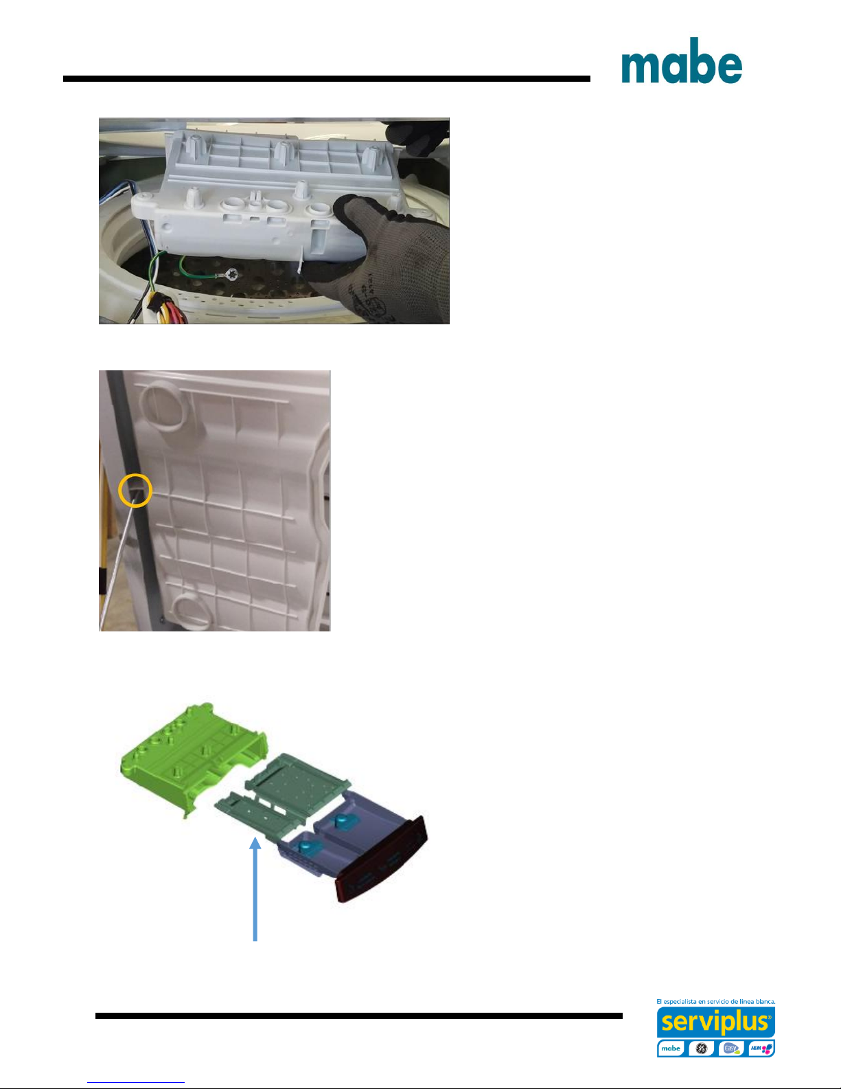
Grasp the control panel and
push it a little toward the front of
the washer in order to see the
pressure tube.
To disengage the pressure tube
from the control board, grasp the
tube where it connects to the
pressure sensor on the board.
Twist the tube while pulling it off
the sensor
IMPORTANT.- Pressure tube
should not be handled vertically
or horizontally as there is a risk
of damage to the pressure
switch, only must disengage as
indicated above.
Disconnect connectors from the
control board and remove six ¼
in. hex screws securing the
control board bracket to the
control panel assembly and
remove.
IMPORTANT.- When reinstalling the control panel assembly, ensure that all ground
wires are reconnected and tested for proper continuity to the ground terminal on the
power cord.
Ingeniería de Servicio
Page 13
- 13 -
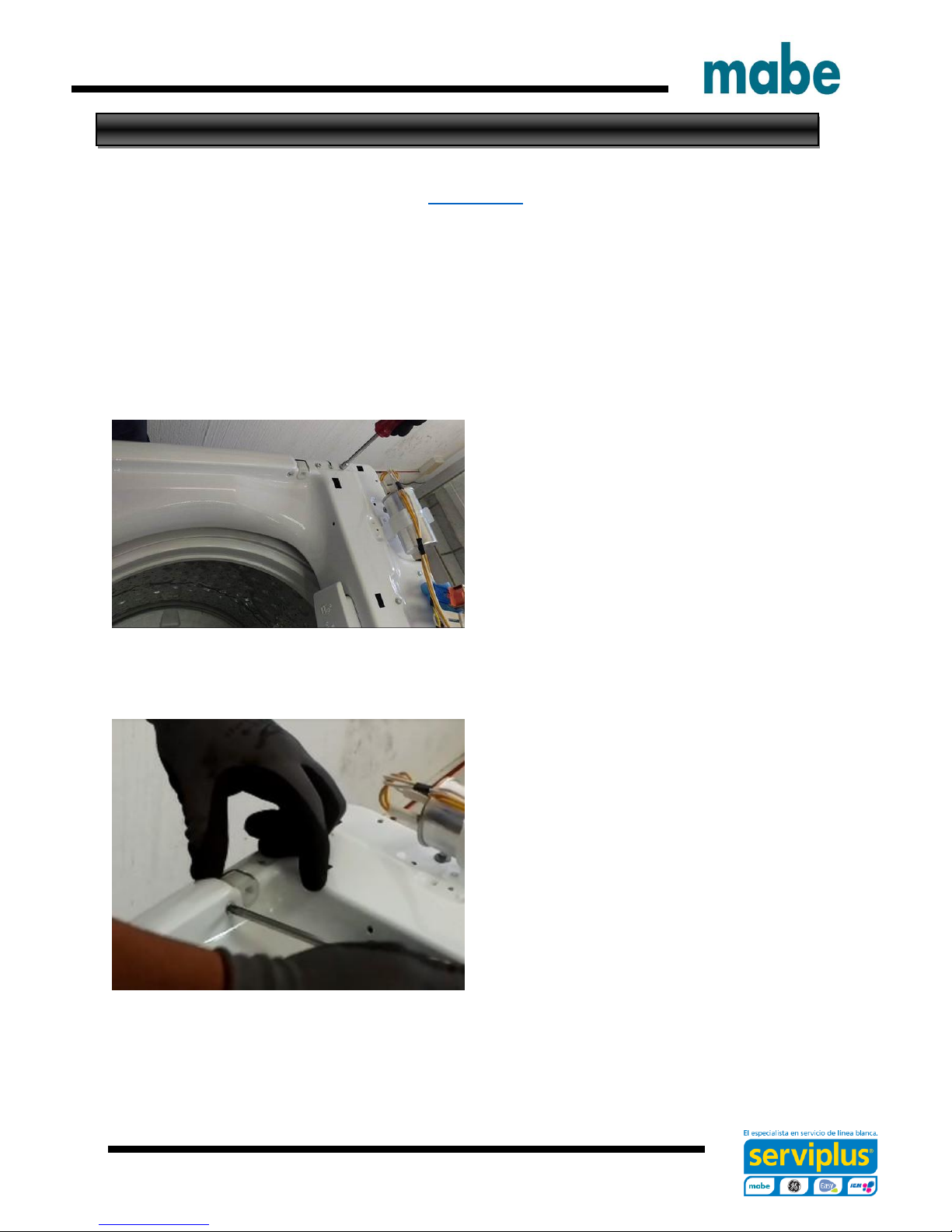
Lid Hinge
Video Link
Hinge removal can be achieved without removing the top cover or disconnecting the
control panel assembly completely.
Remove the lid assembly.
Disengage the control panel from the top cover and slide toward the rear to expose the
hinge mounting screws.
Remove the two ¼ in. hex head hinge
mounting assembly screws
Remove the Philips head screw from the
top cover.
Ingeniería de Servicio
Page 14
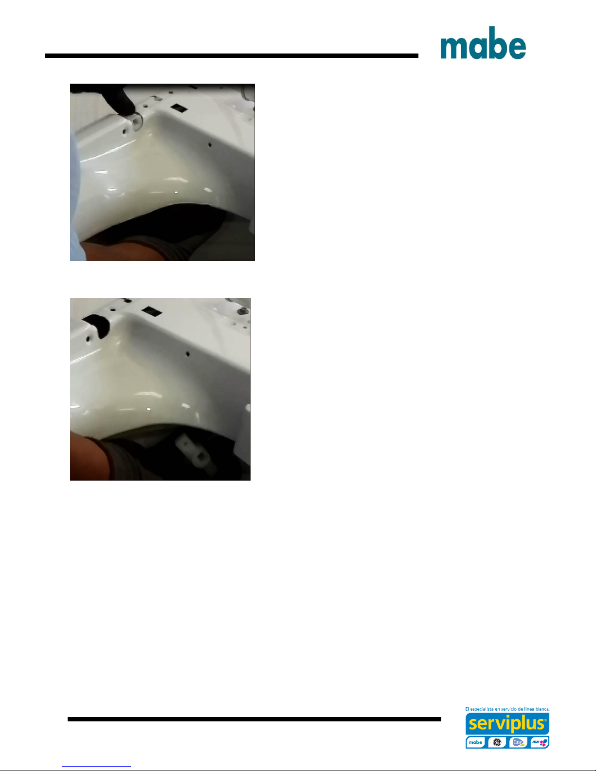
- 14 -
Slide a hand between the tub cover and the top
cover.
Grasp the hinge assembly and remove it from
under the top cover.
Ingeniería de Servicio
Page 15
- 15 -
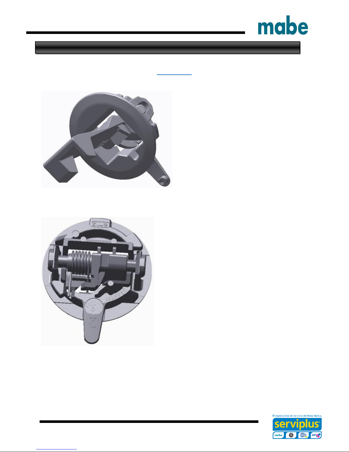
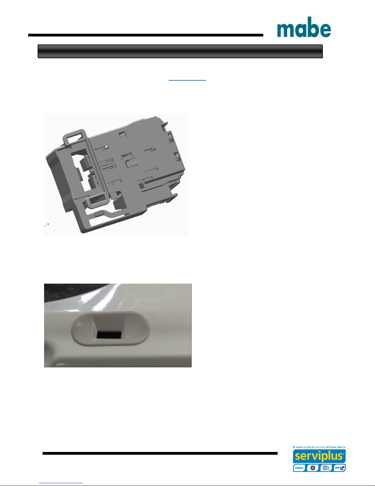
Lid Lock Striker
Video Link
The lid lock striker slides into the lid
lock/switch assembly. When a cycle is
started the lock assembly engages with
the striker preventing the lid from opening
during the cycle.
The latch has spring tension on it to keep it
engaged with the switch/lock assembly
Ingeniería de Servicio
Page 16
- 16 -
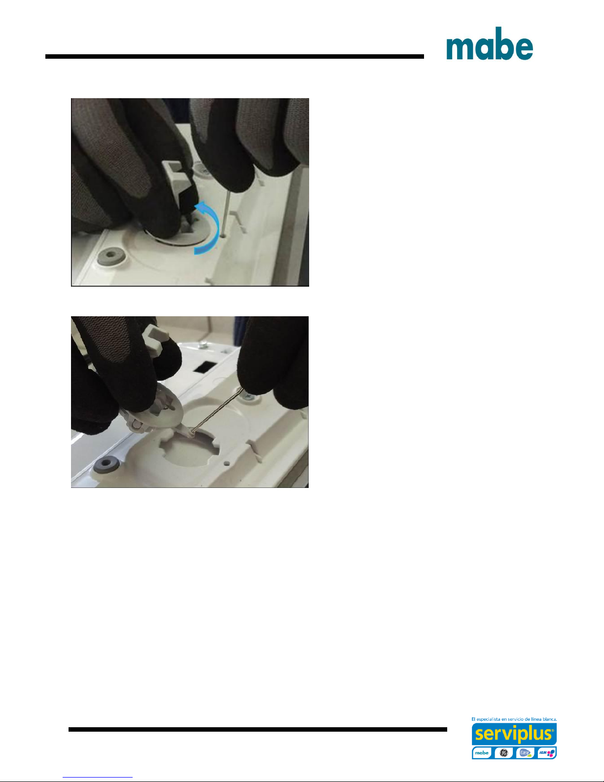
To remove the striker from the lid:
Open the lid.
Using a small screwdriver, insert it into
the small hole below the striker.
Push inward gently on the locking tab
and turn the striker to the left
Pull the striker from the lid
Ingeniería de Servicio
Page 17
- 17 -
Lid Switch/Lock Assembly
Video Link
The lid lock and switch are together in
one part. It requires 120 VAC to activate
the lock.
The approximate resistance of the lock
coil is 70 ohm from Blue – Black from
J513 board connector (at Lid Lock closed
position)
Checking between Black and White wires
at the same board connector will show the
continuity of the lid switch.
To remove the lid switch/lock assembly:
Ingeniería de Servicio
Page 18
- 18 -
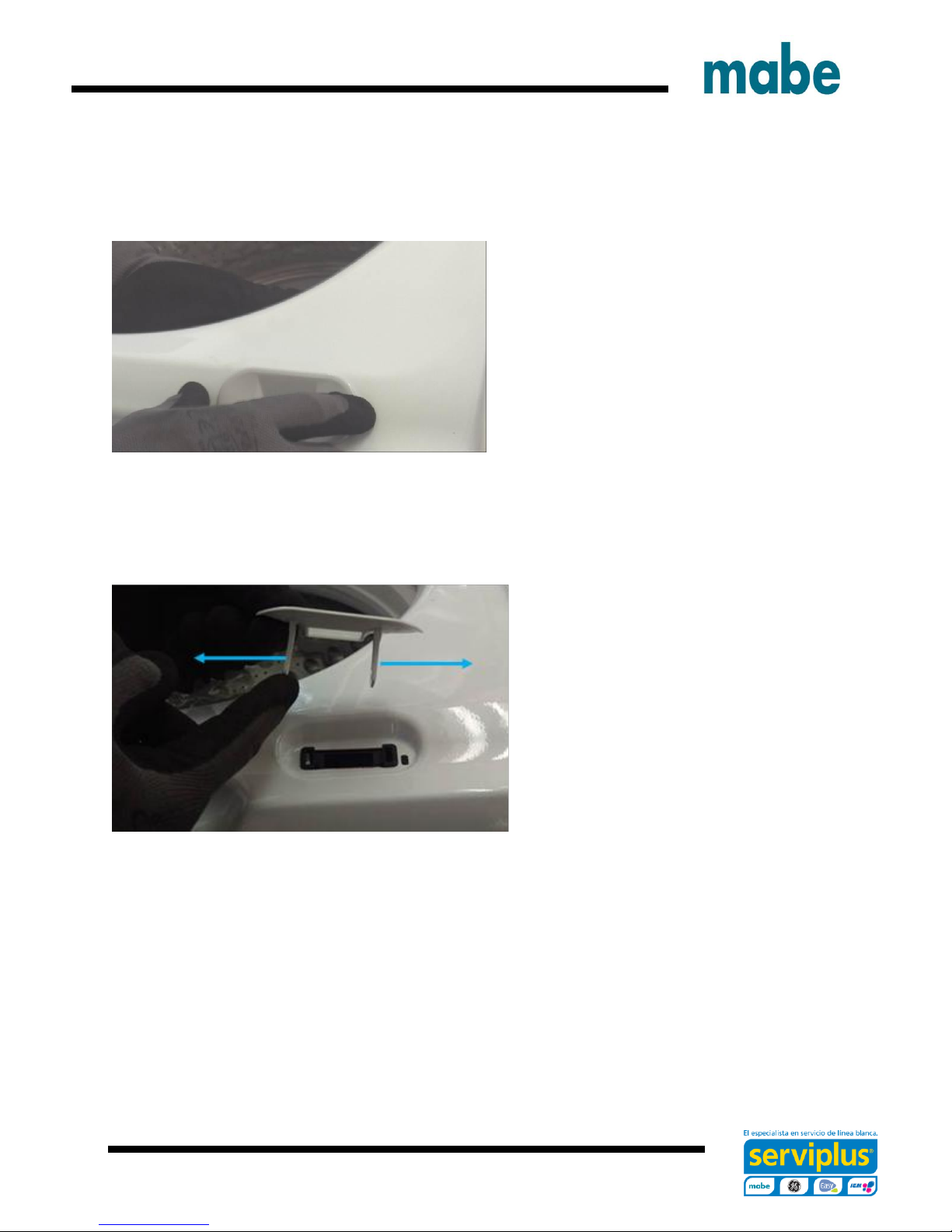
Remove the bezel from the top cover by
reaching under the top cover toward the
lock assembly and feel for the bezel tabs
to extend through the lock body.
Push the tabs out from the side of the
lock body and then push up to
remove the bezel from the top cover
Ingeniería de Servicio
Page 19
- 19 -
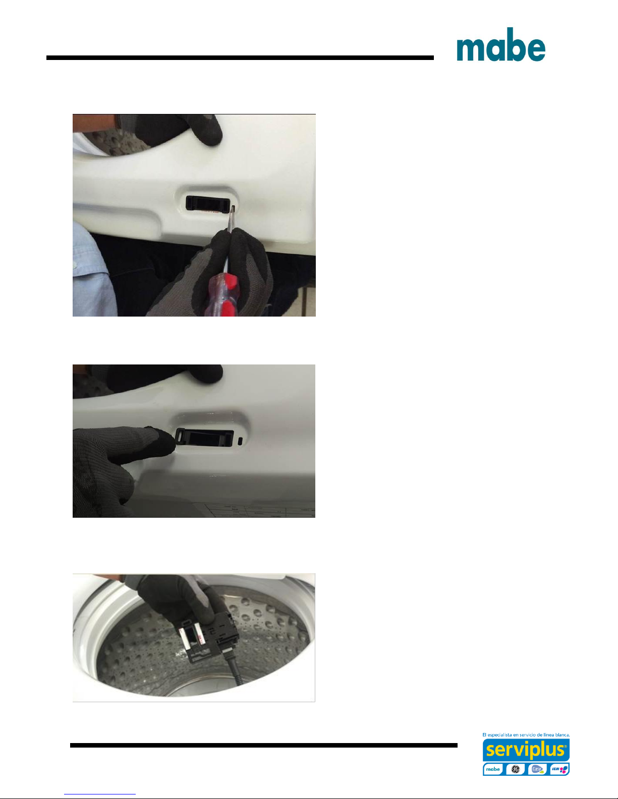
Using a small screwdriver, push down
gently on the tab that prevents the lock
assembly from sliding.
Slide the lock assembly to the left first to
disengage the right tab, then slide to the
right allowing the lock assembly
disengage from the top cover.
Pull the lock assembly from under the
top cover and disconnect the harness
connector.
Ingeniería de Servicio
Page 20

- 20 -
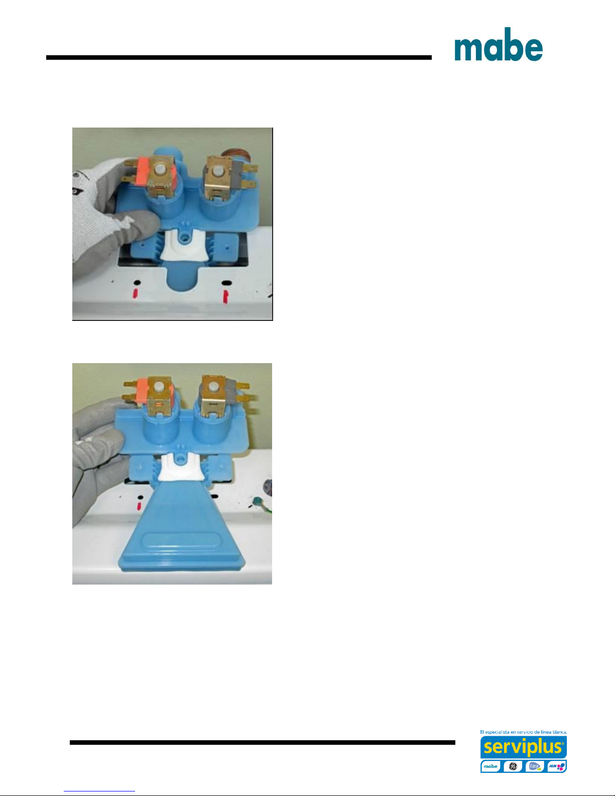
Two Coil Water Valve
Turn water supply off to valve. Hoses do
not need to be disconnected at this time.
Remove two Phillips head screws that go
through the thermistor mounting bracket
into the body of the valve.
Remove thermistor by pulling up on lip of
thermistor. Ensure o-ring is removed with
thermistor.
Ingeniería de Servicio
Page 21
- 21 -
Tilt back of valve up and slide out of top cover.
Once valve is out and held over the basket,
disconnect hoses.
Valve, funnel and Gasket are one part.
Ingeniería de Servicio
Page 22
- 22 -
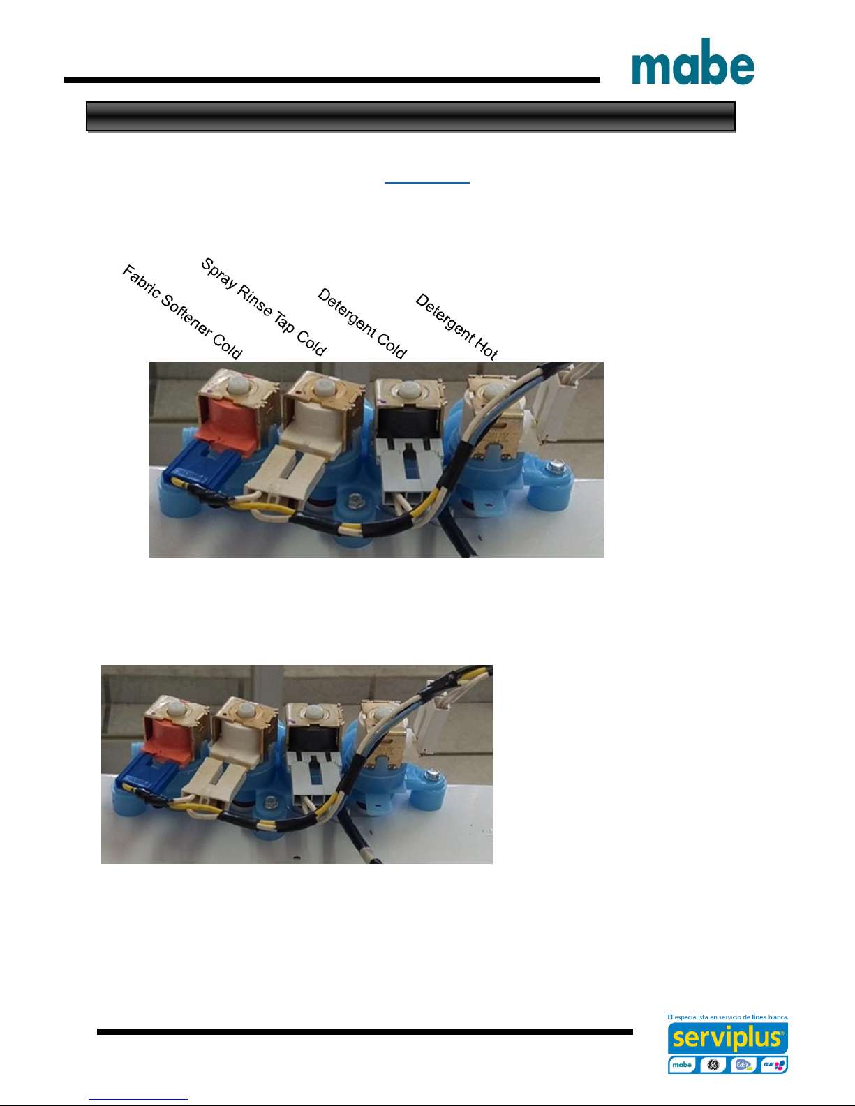
Four Coil Water Valve On GTW680 Model
Video Link
To remove the water valve:
Shut off the water supply to the
washer. Hoses do not need to be
disconnected at this time.
Lean the control panel assembly
back. It does not have to be
completely removed.
Disconnect the harness from the
water valve.
Ingeniería de Servicio
Page 23
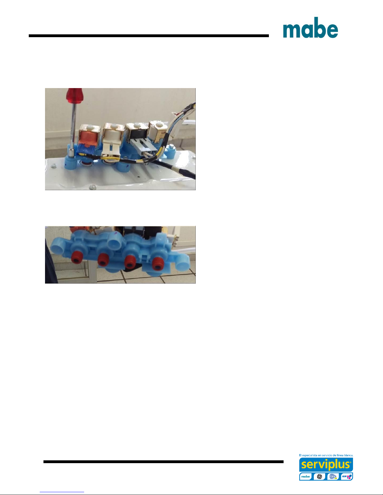
- 23 -
Remove three ¼ in. hex head screws
securing the valve to the top cover and
pull the valve up.
Hold valve over the basket and
disconnect the supply hoses from the
valve.
Quad Valve and the four rubber seals
are together in the same part number
Ingeniería de Servicio
Page 24
- 24 -
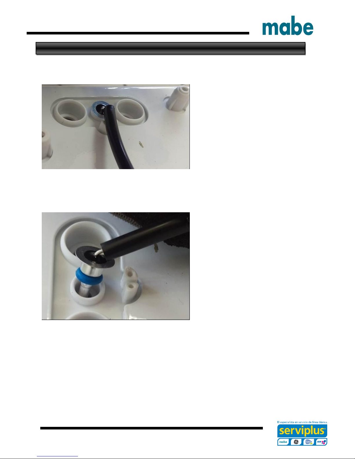
Thermistor Removal
After the water valve is removed, the
thermistor can be accessed and
remove.
It is pushed into the dispenser box
and held in place by the water valve
and is sealed with an O-ring.
Remove thermistor by pulling up on
lip of thermistor. Ensure O-ring is
removed with the thermistor.
Ingeniería de Servicio
Page 25
- 25 -
Dispenser Removal
The dispenser hold detergent and
fabric softener and delivers it at
precise times for the cycle selected.
Water is added to the dispenser from
the water valve to fill and flush the
cups. After the valve turns off the
remaining water in the cup siphons
out.
Video Link
When bleach is added to the bleach
cup it is funneled through to the tub
cover and into the tub.
Remove the backsplash assembly,
water valve and top cover.
Remove the dispenser tray from the
dispenser body.
Remove four ¼ in. hex head screws
from the top cover securing the
dispenser body to the top cover
Ingeniería de Servicio
Page 26
- 26 -
Dispenser Shower Insert
Remove the dispenser body from the
top cover by pushing back slightly on
the dispenser body and pull away
from top cover.
Take care of the back tap of the dispenser body in
order to not damage it.
The dispenser shower insert can be
removed at this time for cleaning if
necessary.
Ingeniería de Servicio
Page 27

- 27 -
Top Cover Removal
Remove the lid assembly and control panel assembly.
.
Disengage the power cord from the top
cover by pulling up on the front of the
power cord grommet.
Slide the power cord grommet forward
Ingeniería de Servicio
Page 28

- 28 -
Pull up off of the top cover.
Remove ground screws.
Slide the harness grommet out toward
the rear of the washer
Ingeniería de Servicio
Page 29

- 29 -
The harness grommet for the lid lock
does not need to be removed unless
replacing the top cover.
If replacing the top cover, squeeze
the two clips on the grommet and
push it through the opening. Transfer
to the new cover
Remove lid assembly and the control panel
assembly.
Remove two ¼ in. hex head screws (one on
each side) at the rear corners of the top
cover.
Slide the harness grommet out toward the
rear of the washer.
Disengage the power cord from the top
cover by lifting up on the front of the cord
grommet, slide forward and up off of the top
cover.
Raise the rear of the top cover up, then pull
forward slightly to disengage from the front
clips that secures the front of the top cover
to the cabinet.
Ingeniería de Servicio
Page 30

- 30 -
Impeller
Dual Action
Agitator
Single Action
Agitator
Impeller and Agitators
Ingeniería de Servicio
Page 31

- 31 -
Impeller
To remove the impeller, pop the
center cap off with a small flat
screwdriver to access the 7/16th in.
hex bolt.
The splined coupler is part of the
impeller and agitators.
Note.- Impeller bolt should be
replaced any time it is removed for
service and torqued to 100 in.lbs.
If it is necessary, use a couple of nose pliers in order
to disassemble the impeller.
Ingeniería de Servicio
Page 32

- 32 -
Dual Stage Agitator
To remove the dual action agitator, the cup section needs to be removed to access the
7/16th in. hex bolt. The bolt is located inside the agitator at the bottom. A long socket
extension (at least 17 in. long) will be needed to remove it.
Note.- Agitator bolts should be replaced any time it is removed for service and torqued
to 100 +/- 5 in-lbs.
Ingeniería de Servicio
Page 33

- 33 -
Single Stage Agitator
Remove the single action agitator by taking the agitator cap off to access the 7/16th in.
hex bolt. The bolt is located inside the agitator at the bottom. A long socket extension
(at least 17 in. long) will be needed to remove it.
Note.- Agitator bolts should be replaced any time it is removed for service and torqued
to 100 +/- 5 in-lbs.
Ingeniería de Servicio
Page 34

- 34 -
Basket Removal
Remove the lid, control panel assembly and top cover.
Remove the tub cover by unclipping eight
clips around the edge and lift it off.
Ingeniería de Servicio
Page 35

- 35 -
Basket Removal
Remove the 1-5/16th in. hub nut by
turning the nut clock-wise to loosen
(reverse threads).
A new hub nut should be used when
reinstalling the basket assembly.
Torque to 100 +/- 10 ft.lbs.
Remove the hub washer
Right position Wrong position
Be care of position when reinstalling the hub washer.
Ingeniería de Servicio
Page 36

- 36 -
Lift the basket out of the tub.
Remove the tub washer.
Ingeniería de Servicio
Page 37

- 37 -
Tub and Cabinet Removal/Replacement
Remove the lid, control panel assembly and top cover.
Remove one Philip screw from the hose
cover.
Remove hose cover.
Ingeniería de Servicio
Page 38

- 38 -
Disengage the rod and spring suspension
from the tub assembly.
Ingeniería de Servicio
Page 39

- 39 -
Tub and Cabinet Removal/Replacement
Once the suspension is disengage, remove the
prop blocks letting the tub assembly rest on the
belt protector.
Raise the cabinet up and over the tub assembly
and set aside.
Note.- Be careful of the tub assembly balance
while removing cabinet.
Ingeniería de Servicio
Page 40

- 40 -
Harness Removal/Replacement
The cabinet needs to be removed to replace the
harness assembly.
Once the cabinet is removed there are two ¼ in. hex
head screws that secure the harness to the side of the
tub that need to be removed.
There is one ¼ in. hex head screw on the bottom.
Ingeniería de Servicio
Page 41

- 41 -
Bottom Component View
Ingeniería de Servicio
Page 42

- 42 -
Drain And Recirculation Pump
Recirculation pump
The GTW680 model has a recirculation pump
located at the front of the bottom of the tub. It
mounts to the tub the same as the drain pump.
Video Link
Drain Pump
The drain pump is located on the right side of the
bottom of the tub. It is mounted directly to the tub
secured by three (3) 3/8th in. hex head bolts.
Video Link
Both pumps are 120 VAC.
The approximate resistances of the pumps checked
from J512 board connector are:
Drain pump – 13.2 ohms
Recirculation pump – 31.7 ohms
Ingeniería de Servicio
Page 43

- 43 -
Drain And Recirculation Pump
Once the bolts are removed, the pump can be pulled from the tub.
Have something to catch excess water. The seal is integrated to the pump as one Part
Number.
Ingeniería de Servicio
Page 44

- 44 -
Drive Belt
The drive belt has five ribs and
can be removed easily turning
the pulley to walk the belt off.
To reinstall the belt, put it on the
motor pulley first.
Stretch the belt around the
transmission pulley as far as it can go.
Then rotate the pulley until the belt is
in place. Be sure all the ribs of the
belt.
Ingeniería de Servicio
Page 45

- 45 -
Drive Motor
Video Link
There are two different horsepower
motors. One third and one half
horsepower motors. They are both
120 VAC reversible motors.
Resistances are ½ hp.- White –
Brown and White – Yellow approx.
3.1 ohm.
1/3rd hp. approx. 3.8 ohm from J511
board connector.
To remove the motor:
Remove the belt and fan pulley. The pulley is held on by a 9/16 in. lock nut.
Use a new nut when reinstalling the pulley and torque to 110 in-lbs.
Disconnect the motor harness connector.
Ingeniería de Servicio
Page 46

- 46 -
Drive Motor
Unclip the hall/speed sensor from the
motor.
Remove two ½ in. bolt mounting the
motor to the tub letting the motor
come loose from the platform.
When reinstalling the motor mounting
bolts torque to 110 in-lbs
Note.- If the hall/speed sensor is wire tied to the motor when replacing the motor, order
both, the motor and hall/speed sensor.
Ingeniería de Servicio
Page 47

- 47 -
Mode Shifter Assembly
The mode shifter either engages or
disengages the clutch with the
transmission pulley depending on
whether the cycle is in spin or
agitate.
The clutch home position is
engaged with the pulley or ready for
spin.
It has a 120 VAC motor.
Resistance of the mode shift motor
from Red – Blue is 5700 +/- 10 %
ohm from J512 board connector.
To remove the mode shifter:
Remove the transmission pulley and nut. The pulley is held on by a 9/16 in. lock nut.
Use a new nut when reinstalling the pulley and torque to 110 in-lbs.
Ingeniería de Servicio
Page 48

- 48 -
Mode Shifter Assembly
Disconnect the mode shifter motor
harness connector.
Remove two 3/8th in. hex head
mounting bolts. This will allow the
complete mode shifter assembly to be
removed with the clutch.
The clutch spring and spring washer
will come off as well. When
reinstalling be sure to install the
spring washer before the clutch
spring.
Ingeniería de Servicio
Page 49

- 49 -
Platform Transmission Assembly
The platform transmission
assembly is one complete part with
the exception of two harness
connector brackets and one motor
splash guard. These will need to be
transferred to the new platform
assembly when replacing the
platform transmission assembly.
The platform assembly is secured
to the tub by nine 3/8th in. hex head
bolts circled. One of these bolts
also holds one of the harness
brackets to the platform.
To remove the platform assembly
after all other components have been
removed, remove the nine 3/8th in.
hex head bolts and pull the platform
away from the tub.
Note.- The bottom of the tub can be
used to pry the platform transmission
assembly off of the tub.
The tub seal is pressed on to the
platform transmission assembly. If
there is a leak from the seal, the
complete transmission will need to be
replaced.
Ingeniería de Servicio
Page 50

- 50 -
Platform Transmission Assembly
To reinstall the platform assembly
to the tub, slide the shaft of the
transmission into the opening of the
tub.
Press the tub seal into the tub
opening.
Note.- Line the guide post with the
opening in the platform.
Tighten the nine hex head bolts in
a crisscross pattern so that the seal
is pulled into the tub evenly and
securely
This is done by tightening each bolt about ¼ of the way in at a time.
Torque to 70 in-lbs.
Ingeniería de Servicio
Page 51

- 51 -
Schematic
Ingeniería de Servicio
Page 52

- 52 -
Control Board User Interface
Ingeniería de Servicio
Page 53

- 53 -
Consumer Error Mode Entry
Entry into Consumer Error Mode
From an idle state only (all LEDs off), press and hold Start button for 10 seconds.
After holding Start for 10 seconds, all LEDs will turn on, signifying the user may
release the Start button.
Behaviors While In Consumer Error Mode
The Pause and Lid Locked LEDs should be constantly blinking while in CEM.
The first fault, if present, will show on the display.
Pressing Start will display the next fault code.
o Models without 7-segment display: Fault code will blink in binary – the
consumer will report which LEDs are blinking and which are not. See Binary
Display Fault Chart.
o Models with 7-segment display: Fault code will blink on the 7-segment display.
At the end of the fault list or if no faults present.
o Models without 7-segment display: All status LEDs will blink.
o Models with 7-segment display: 7-segment display will blink “-“.
Exiting Consumer Error Mode
Pressing any button (other than Start) or turning any knob will exit Consumer Error
Mode.
Consumer Error Mode will time out after 10 minutes.
Ingeniería de Servicio
Page 54

- 54 -
Your washer is equipped with Consumer Help Indicator (CHI) is our way to
communicate a simple remedy for some situations that you perform without the need to
call for service. The chart below describes the helpful messages you may notice
scrolling on your display when you return to start another load. These messages will
provide simple remedies you can quickly perform.
To ensure that you see the message, the washer will scroll the message continually
until you interact in some way with the controls.
“Ob” (Out of balance)
After the wash cycle, the clothing wasn´t evenly distributed
enough to spin out the water. Redistribute the clothes more
evenly in the washer and then run a Drain & Spin cycle
“Po” (Water took too long
to Pump Out)
Resume cycle or enter Drain & Spin. If water pumps out,
then the clog has likely cleared. If water remains in the
washer, check for clogged or pinched drain hose. This
situation could be more likely to appear, over time, if the
external drain hose has been extended or restricted
“H2O Supply” (Water not
entering washer)
Check your house water supply. Did you forget to turn on
one or both supply valves after installation or coming back
from vacation? As soon as the message starts to scroll, the
washer will initiate a 3 minute lock-out period. The washer
controls won´t respond/change during this time. After the 3
minutes, you can begin your cycle again. If you try to bypass
the lock-out period by unplugging the washer, the 3 minute
timer will start over again.
“”CAnCELEd”
If your machine has stopped itself before the cycle
completed, CAnCELEd will scroll in the display. On models
without a display, the two furthest right LED lights will flash.
This indicates that an error has occurred. Try to run a Drain
& Spin cycle to see if it will clear. If it does not clear, call
800GECARES (800.432.2737), in Canada, call
1.800.561.3344 for service.
Consumer Help Indicator
Ingeniería de Servicio
Page 55

- 55 -
Service Mode Entry
Field Service Mode Entry
From an idle state only (all LEDs off), press and hold Start button while rotating the
cycle selection knob 180 degrees (7 clicks) and then release the Start button.
Once service mode is entered all LEDs will be flashing.
o On 7-segment display models: (0) will be displayed for test (0).
o On models without a 7-segments display: All of the status LEDs above the
cycle knob will be lit.
The cycle selection knob is now used to control the test selection menu.
o Rotating the knob clockwise will increment the test numbers in the display.
o Rotating the knob counter clockwise will decrement the test number in the
display.
o Models without 7-segment display: Will display test using the status lights
above the cycle knob in a binary format. (See Binary Chart).
o Turning the knob to go to a different test will terminate any current active
state.
Once the test number is selected, pressing Start will begin the selected test.
Exit Field Service Mode
Field service mode will time out after 30 minutes if there is no user activity.
Models without 7-segment display: Press and hold the Start button for 3 seconds.
Models with a 7-segment display: Press Power button.
Once the washer is in Service Mode, the following service features are available via the
cycle knob (on some models):
Ingeniería de Servicio
Page 56

- 56 -
Fault/Test #
displayed on
7-segment display
When entered into service mode
Service Mode Test
0 All LEDs on
1 Fault Codes
2 Personality ID
3 UI Software Version (Critical)
4 UI Software Version (Non-Critical)
5 XML Version (Non-critical)
6 Hot Water Valve
7 Cold Water Valve
8 Fabric Softener Dispenser
9 Spray Rinse Valve
10 Preasure Sensor
11 Recirculate Pump
12 Drain Pump
13 Lid Switch
14 Spin
15 Agitate
16 Clear all F Codes
17 Change Personality
18 Analog knob
Filled circles indicate
light on
Fault/Test # displayed in
binary format using
cycle status ligths
Binary Display Fault Chart
Display Test and Fault Chart
Ingeniería de Servicio
Page 57

- 57 -
Knob Index / Test
number (Displayed
on SSD, 7-segment
display, if present)
(Without SSD will
be displayed in
binary format. (See
Binary Chart)
Test Name
Description of test
If tests call for numbers to be shown it will:
(Display on SSD, 7-segment display, if present)
(Without SSD will be displayed in binary format.
(See Binary Chart) Turning the cycle knob will
index to the next or prior test.
0
All LEDs on
All LEDs on the display will be blink including “88”
on the (7-segment display) SSD at a rate of 1 Hz.
1
Fault Codes
Models without 7-segment display:
Faults will be shown:
- On Start button press, blink first fault code in
binary. (See Binary Chart)
- On next Start button press, blink next fault
code.
- At end of list OR if no fault codes are present,
blink all LEDs.
- Pressing Start at the end of the fault list will
wrap back around.
- Use the fault sequence.
7-segment display models:
On Start button press, blink first fault code
Display fault code in SSD
At end of list OR if no fault codes are present,
washer will flash “- -“.
2
Personality
ID
Pressing Start will start the test.
Flash the set personality after pressing Start.
Models without SSD use binary to show
personality.
Model with SSD will display personality.
(See Personality ID Chart for the correct ID for
the model being checked).
Service Mode Tests
Ingeniería de Servicio
Page 58

- 58 -
Knob Index / Test
number (Displayed
on SSD, 7-segment
display, if present)
(Without SSD will
be displayed in
binary format. (See
Binary Chart)
Test Name
Description of test
If tests call for numbers to be shown it will:
(Display on SSD, 7-segment display, if present)
(Without SSD will be displayed in binary format.
(See Binary Chart) Turning the cycle knob will
index to the next or prior test.
3
UI Software
Version
(Critical)
After entering this test, press the Start button to
toggle through the software version number as
follows:
Example: v01.23
High end UI
1st press – “01” on 7SD
2nd press – “23” on 7SD
Low end UI (See Version Diagram below)
Major version (Pause LED ON)
3rd press – Display 2 in binary
4th press – Display 3 in binary
4
UI Software
Version (Noncritical)
After entering this test, press the Start button to
toggle through the software version number as
follows:
Example: v01.23
High end UI
1st press – “01” on SSD
2nd press – “23” on SSD
Low end UI (See Version Diagram below)
Major version (Pause LED ON)
1st press – Display 0 in binary (all LEDs off)
2nd press – Display 1 in binary
Minor version (Lid Locked LED ON)
3rd press – Display 2 in binary
4th press – Display 3 in binary
Service Mode Tests
Ingeniería de Servicio
Page 59

- 59 -
Knob Index / Test
number (Displayed
on SSD, 7-segment
display, if present)
(Without SSD will
be displayed in
binary format. (See
Binary Chart)
Test Name
Description of test
If tests call for numbers to be shown it will:
(Display on SSD, 7-segment display, if present)
(Without SSD will be displayed in binary format.
(See Binary Chart) Turning the cycle knob will
index to the next or prior test.
5
XML Version
(Non-Critical)
Example: v01.23
High end UI
1st press – “01” on SSD
2nd press – “23” on SSD
Low end UI (See Version Diagram below)
Major version (Pause LED ON)
1st press – Display 0 in binary (all LEDs off)
2nd press – Display 1 in binary
Minor version (Lid Locked LED ON)
3rd press – Display 2 in binary
4th press – Display 3 in binary
NOTE: We only show the non-critical version
number because the critical XML version number
must match the application non-critical version
number for the control to boot. If you get to
service mode, then the XML critical version is
correct. If not, update software.
6
Hot Water
Valve
Pressing Start will toggle the hot water valve on
and off. Test will have a timeout for how long
valve will be on (1 minute). The valve will turn off
when the test is exited.
7
Cold Water
Valve
Pressing Start will toggle the cold water valve on
and off. Test will have a timeout for how long
valve will be on (1 minute). The valve will turn off
when the test is exited.
Service Mode Tests
Ingeniería de Servicio
Page 60

- 60 -
Knob Index / Test
number (Displayed
on SSD, 7-segment
display, if present)
(Without SSD will
be displayed in
binary format. (See
Binary Chart)
Test Name
Description of test
If tests call for numbers to be shown it will:
(Display on SSD, 7-segment display, if present)
(Without SSD will be displayed in binary format.
(See Binary Chart) Turning the cycle knob will
index to the next or prior test.
8
Fabric
Softener
Dispenser
Pressing Start will toggle the fabric softener valve
on and off.
Test will have a timeout for how long valve will be
on (1 minute). The valve will turn off when the
test is exited.
9
Spray Rinse
Valve Check
Pressing Start will toggle the spray rinse valve on
and off.
Test will have a timeout for how long valve will be
on (1 minute). The valve will turn off when the
test is exited.
10
Pressure
Sensor
Pressing Start will start the test.
Pressure sensor test will have a time out.
All valves will turn on.
All LEDs will blink at start of test.
Stop blinking LEDs as approximate water levels
are crossed.
The levels are:
2”
3”
4”
5”
6”
7” Water valves shut off at this level.
11
Recirculate
Pump
Pressing Start will toggle the recirculation pump
on and off.
Test will have a timeout (1 minute) for how long
recirculation pump will be on.
The recirculation pump will turn off when the test
is exited.
Service Mode Tests
Ingeniería de Servicio
Page 61

- 61 -
Knob Index / Test
number (Displayed
on SSD, 7-segment
display, if present)
(Without SSD will
be displayed in
binary format. (See
Binary Chart)
Test Name
Description of test
If tests call for numbers to be shown it will:
(Display on SSD, 7-segment display, if present)
(Without SSD will be displayed in binary format.
(See Binary Chart) Turning the cycle knob will
index to the next or prior test.
12
Drain Pump
Pressing Start will toggle the drain pump on and
off.
Test will have a timeout (4 minute) for how long
drain pump will be on.
The drain pump will turn off when the test is
exited.
14
Spin
Pressing Start will start the test. Spin test will
perform child safety algorithm before it starts to
spin. (Two (2) sprays of water before locking the
lid). The lid must be closed to start the test. If lid
is opened the Locked LED will blink.
When started, the mode shift to spin will occur if
required and the lid will be locked.
When mode shift is complete, the washer will
begin spinning to max spin speed for the model
being tested.
Spin test will have a timeout (4 minute).
Be sure to only run this test with an empty basket
as there is no OOB detection during this test.
The spin will stop when the test is exited.
The lid will unlock once the speed reaches 0 after
the test is exited.
Service Mode Tests
Ingeniería de Servicio
Page 62

- 62 -
Knob Index / Test
number (Displayed
on SSD, 7-segment
display, if present)
(Without SSD will
be displayed in
binary format. (See
Binary Chart)
Test Name
Description of test
If tests call for numbers to be shown it will:
(Display on SSD, 7-segment display, if present)
(Without SSD will be displayed in binary format.
(See Binary Chart) Turning the cycle knob will
index to the next or prior test.
15
Agitate
Pressing Start will start the test. Agitate test will
perform child safety algorithm before it starts to
agitate. The lid must be closed to start the test. If
lid is opened the Locked LED will blink.
When started, the mode shift to agitate will occur
if required.
When mode shift is complete, the washer will
begin agitating.
The test will pause if the lid is opened after
starting. The test will resume on lid close if it was
running when opened.
The test will stop when the test is exited.
16
Clear all Fault
Codes
Pressing Start will clear all fault codes.
17
Change
Personality
Pressing Start will start the test.
Press Start button again and the next valid
personality should be displayed.
Press and hold the Start button to select the
correct personality.
18
Analog Knob
Pressing Start will start the test.
Each options knob is represented by a specific
corresponding status LED (for left options knob to
the far left status LED).
When knob position changes, the LED for the
specific knob blinks.
With each click to the right, the LED for the
specific knob blinks faster.
With each click to the left, the LED for the specific
knob blinks slower.
Service Mode Tests
Ingeniería de Servicio
Page 63

- 63 -
Fault
Code
(Hex)
Name
Description
Repair Action
1
Lock
Monitor
Lid lock didn’t occur
or lid lock signal not
seen by control due
to lack of connection.
Check the resistance of the lid lock assembly.
Check the harness for open wires and or
connectors from the board to the lock
assembly.
If lock assembly and harness prove good at
the time of service, replace the lid lock
assembly.
2
Lid
Monitor
Control did not get lid
closed signal from
switch while motor
was moving. Could
mean the switch
didn’t close or control
didn’t get the signal
because of lack of
connection.
Replace control if this fault happens
repeatedly.
3
Locked
Rotor
Monitor
For 5 straight
seconds control not
seeing signal
changes indicating
the motor is turning
while trying to spin.
Could mean the
motor isn’t rotating or
Control didn’t get the
signal because of
lack of connection
Physically check the washer for anything
preventing motor movement.
Check harness and harness connections from
the control to the motor.
Verify hall sensor is connected to the main
harness. Put washer in Service Mode and run
Test 13. Spin Test. If hall sensor is bad or
disconnected, the basket will start to spin
normally and then stop spinning after
approximately 5 seconds. Ensure hall sensor
is properly connected and positioned on the
motor. If basket spins for approximately 15
seconds, the hall sensor is most likely NOT the
cause.
TCO should reset in approximately 45 minute.
If TCO is tripped, make sure motor moves
freely and that nothing is jamming it. Replace
motor if it does not.
Fault Codes
Ingeniería de Servicio
Page 64

- 64 -
Fault
Code
(Hex)
Name
Description
Repair Action
4
Reset
Monito
r
Control is resetting
the software by itself
due to criteria it
believes could
resolve itself upon
reset.
Check for loose connections at the control.
Reconnect if any.
Check for recommended house line voltage
to the washer.
5
Mode
Shifter
Control didn’t see the
transition from Agitate
ti Spin or vice-versa
in the time required.
Could mean the shift
didn’t occur or
Control didn’t get the
signal because of
lack of connection
Check mode shifter coupler for damage and
the ability to slide in and out freely.
Using an Ohm meter, check to ensure mode
shifter switch is in the open position.
Check resistance of mode shifter motor
(approximately 5,700 ohms)
Check for 120 VAC to the mode shifter motor
at the control J512 connector.
If voltage is present, replace the mode shifter.
If voltage is not present at the control, replace
control.
6
Critical
Flood
Level
by
Pressu
re.
Pressu
re level
exceed
s 17.5
inches
above
pressu
re port.
Control received an
extended period of
pressure readings
that is nearing overflow levels. Pressure
17.5”.
Voltage Output must
be present. Could
mean water did get
that high due to
briefly stuck water
valve. Voltage output
of sensor too high for
actual water level
because of sensor or
water in pressure
tube increasing
pressure.
Check pressure tube for pinches where it
goes through top cover grommet.
Check pressure tube for trapped water.
Check for any leaking water valves.
Check the output voltage from the pressure
sensor to ensure it matches the water level in
the basket according to the pressure sensor
chart. If it does not, the control will need to be
replaced as the pressure sensor is mounted
directly to the control.
Fault Codes
Ingeniería de Servicio
Page 65

- 65 -
Fault
Code
(Hex)
Name
Description
Repair Action
7
Flood
Warnin
g Level
by
Pressu
re.
Pressu
re level
exceed
s 16.5
inches
above
pressu
re port.
Main micro received
and extended period
of pressure readings
that is greater than
maximum allowable
fill volume. Pressure
16.5”. Voltage output
must be present.
Could mean water did
get that high due to
briefly stuck water
valve. Voltage output
of sensor too high for
actual water level
because of sensor or
water in pressure
tube increasing
pressure.
This can happen if a large wet load is placed
in the washer.
Check pressure tube for pinches where it
goes through top cover grommet.
Check pressure tube for trapped water.
Check for any leaking water valves.
Check the output voltage from the pressure
sensor to ensure it matches the water level in
the basket according to the pressure sensor
chart. If it does not, the control will need to be
replaced as the pressure sensor is mounted
directly to the control.
Fault Codes
Ingeniería de Servicio
Page 66

- 66 -
Fault
Code
(Hex)
Name
Description
Repair Action
8
Pressure
Sensor Loss
This determines if
there has been a
too great of a
difference in the
pressure sensor
reading and the
expected pressure
sensor reading for
the amount of
water the control
calculated it has
put in. It assumes
there is a pressure
leak, a clog in the
pressure
hose/system
delaying the
increase in
pressure, or a
significant amount
water leaking out.
Check house water supply are turned on.
Check pressure tube for pinches where it
goes through top cover grommet.
Check pressure tube for trapped water.
Check for any leaking water valves.
Check the output voltage from the pressure
sensor to ensure it matches the water level
in the basket according to the pressure
sensor chart. If it does not, the control will
need to be replaced as the pressure sensor
is mounted directly to the control.
9
Lid Switch
Redundancy
Start attempted for
a 4th cycle when
the previous 3
cycles have
completed with
backup micro
seeing lid open.
Could mean the
switches didn’t
occur or backup
processor didn’t
get the signal
because of lack of
connection. See
Fault # 2 as well.
Open and close the lid to clear the error.
Check harness and connectors that go to
the lid switch.
If the error will not clear, replace the lid
switch.
Fault Codes
Ingeniería de Servicio
Page 67

- 67 -
Fault
Code
(Hex)
Name
Description
Repair Action
10
Mode
Shift
Feedb
ack
Monito
r
Signal feedback state
from the mode shifter
(agitate or spin) and
the state requested by
the control are not the
same and the basket
or agitator is rotating
faster than 3-4 RPM.
Agitate mode
feedback signal is no
voltage.
Check mode shifter coupler for damage and
the ability to slide in and out freely.
Use ohm meter to ensure harness shows
continuity to the mode shifter from the
control..
Check resistance of mode shifter motor
(approximately 5.7 K ohms)
Check for 120 VAC to the mode shifter motor
at the control J512 connector.
If voltage is present and no operation,
replace the mode shifter.
If voltage is not present at the control,
replace control.
11
Clock
Monito
r
1. AC power line
frequency is not 60
Hz.
2. Software failure.
Check the frequency of the AC power outlet.
If it is more than a few Hz off of 60 Hz.
If house frequency is good, update software.
12
Redun
dant
Flood
Conditi
on
Backup Processor
received an extended
period of pressure
readings that is
nearing over-flow
levels.
Pressure 18.0”
Voltage Output must
be present. Could
mean water did get
that high due to briefly
stuck water valve.
Voltage output of
Sensor too high for
actual water level
because of Sensor or
water in Pressure tube
increasing pressure.
Check pressure tube for trapped water.
Check each valves Operation… Replace
Water Valve.
Check the output voltage from the pressure
sensor to ensure it matches the water level in
the basket according to the pressure sensor
chart. If it does not, the control will need to be
replaced as the pressure sensor is mounted
directly to the control.
If the pressure tube is intact, replace control.
Fault Codes
Ingeniería de Servicio
Page 68

- 68 -
Fault
Code
(Hex)
Name
Description
Repair Action
13
Redun
dant
Lid
Unlock
ed
In spin mode, the lid
switch feedback has
voltage (lid closed), for
more than 5 seconds
the motor speed
feedback assumes the
basket is spinning > 45 RPM when the lid
lock feedback has no
voltage (Lid
Unlocked). Lid Switch
Feedback has no
Voltage when the
BRPM is > 4-5 RPM.
Check lid switch continuity at J513 on the
control.
Check continuity of lid lock position. Opened
or Closed.
Check for proper operation of lid lock, 120
VAC while activating.
Check lid lock wiring harness from the
control to lock assembly.
If lid lock assembly and harness are OK,
replace control board.
14
Lid
Lock
Failure
Signal received by
control is indicating the
lock will not lock or
unlock when
requested or the lid
switch is indicating
open when the signal
received indicated
locked.
Verify that the lid lock is not blocked by any
external debris.
Check lid switch continuity at J513 on the
control.
Check continuity of lid lock position. Opened
or Closed.
Check for proper operation of lid lock. 120
VAC while activating.
Check lid lock wiring harness from the
control to lock assembly.
If lid lock assembly and harness are OK,
update the software.
15
Water
Temp
Sensor
invalid
1. Thermistor
disconnected/not
present.
2. Failed Thermistor
Check thermistor resistance from connector
J701 on the control board. Validate the
resistance matches the table in mini-manual.
Check wiring harness and connectors.
Replace thermistor
Fault Codes
Ingeniería de Servicio
Page 69

- 69 -
Fault
Code
(Hex)
Name
Description
Repair Action
16
Adapti
ve
Drain/
Slow
Drain
The total number of
times during machine
life the actual amount
of time the pressure
sensor indicated the
wash water had
drained to empty
exceeded the
calculated time by the
software.
This fault is set when adaptive drain cycle
occurs to try to remove the rest of water in
tub.
If the adaptive drain cycle times out. The
control will run a Drain Pump Clearing
algorithm to free the pump impeller of debris.
Then it will finish draining. If drain clearing
algorithm fails look for fault 18.
If fault 16 is 100 and fault 18 never occurs
there is no problem… If fault 16 and fault 18
equal each other in faults, then look for drain
blockages including house standpipe.
17
Dry
Load
Sense
Timeo
ut
Dry load sense times
out and moves to the
next part of the cycle
selected. This occurs
when the washer is
not reaching the target
speed within a defined
time limit for the load
type selected.
1. Check for water in the bottom of the tube. If
so drain and try cycle again.
2. Check the basket for excessive friction.
Basket should spin freely. If not, find source of
friction and remove it.
Fault Codes
Ingeniería de Servicio
Page 70

- 70 -
Fault
Code
(Hex)
Name
Description
Repair Action
18
Drain
Pump
Clearing
algorith
m failed.
While draining the
pressure sensor
value for water level
did not indicate the
washer was empty
before the Max
Continuous Drain
ON time was
reached.
This fault is set and will be seen with fault 16
when Drain Pump Clearing Algorithm failed to
remove the blockage and the rest of water in
tub.
Check the drain pump for blockage.
Check installation instructions for proper
standpipe height.
Check pressure tube for pinches where it
goes through top cover grommet.
Check pressure tube for trapped water.
Check the output voltage from the pressure
sensor to ensure it matches the water level in
the basket according to the pressure sensor
chart. If it does not, the control will need to be
replaced as the pressure sensor is mounted
directly to the control.
Check resistance of the pump (13.2 ohms)
from J512 connector on the control.
If open circuit, check wiring harness to the
pump and pump motor.
Check for 120 VAC to the drain pump.
If voltage is present and pump does not
operate, replace pump.
If voltage is not present, replace IMC
(Interface Machine Control).
19
UI State
Timeout
Washer was paused
for over 12 hours
This is normal operation. This will happen if
the consumer and or control switched cycle to
a paused state.
Fault Codes
Ingeniería de Servicio
Page 71

- 71 -
Fault
Code
(Hex)
Name
Description
Repair Action
20
Critical
Flood
Level by
Gallons
Water volume into
the tub exceeded 41
gallons as calculated
by the control.
1. Pressure tube is
momentarily
pinched, has water in
it, partial blockage if
Flood fault 12
occurs.
2. Low water
pressure/flow or
permanent pressure
system blockage if
NO Flood fault 12
occurs.
Check pressure tube for pinches where it
goes through top cover grommet.
Check pressure tube for trapped water.
Check for any leaking water valves.
Check home water pressure.
Check the output voltage from the pressure
sensor to ensure it matches the water level in
the basket according to the pressure sensor
chart, if it does not, the control will need to be
replaced as the pressure sensor is mounted
directly to the control.
21
Flood
Warning
Level by
Gallons
Water volume into
the tub exceeded
36.3 gallons as
calculated by the
control. Stops filling.
1. Pressure tube is
momentarily pinched
or has water in it,
partial blockage if
Flood fault 6, 7, or 12
occurs.
2. Low water
pressure/flow or
permanent pressure
system blockage if
NO Flood fault 6, 7,
or 12 occurs.
Check pressure tube for pinches where it
goes through top cover grommet.
Check pressure tube for trapped water.
Check for any leaking water valves.
Check home water pressure.
Check the output voltage from the pressure
sensor to ensure it matches the water level in
the basket according to the pressure sensor
chart, if it does not, the control will need to be
replaced as the pressure sensor is mounted
directly to the control.
Fault Codes
Ingeniería de Servicio
Page 72

- 72 -
Fault
Code
(Hex)
Name
Description
Repair Action
22
Out of
Balance
(OOB)
during
Dry Load
Sense.
Large wet/OOB
load being washed.
This is set if OOB
condition is
detected during dry
load sense
algorithm. Dry load
sense will be
abandoned and wet
load sense will be
started.
1. Check for excessively OOB load. Customer
Education on how to distribute load.
2. Check the basket for excessive friction or
for being excessively out of round. Basket
should spin freely and without wobble. If
friction is found, remove it. If basket is bad
replace it.
23
Critical
Lid Lock
1. Lock blockage.
2. Lid Lock failure.
Will not lock or
unlock or is locked
while lid is opened.
Verify that the lid lock is not blocked by any
external debris.
Check lid switch continuity at J513 on the
control.
Check continuity of lid lock position. Opened
or Closed.
Check for proper operation of lid lock. 120
VAC while activating.
Check lid lock wiring harness from the
control to lock assembly.
If lid lock assembly and harness are OK,
replace control board.
24
Lid Logic
Failure
Lid switch failure.
This fault is sent if
the system
perceives the lid to
be both OPEN and
LOCKED for 5
consecutive
seconds.
1. Check harness and connections from the
control to the lid lock assembly for damage
and continuity.
2. Run a spin cycle. Pull up on the lid during
spin for more than 5 seconds and see if this
fault occurs. Replace lid lock assemble.
3. If above does not correct the fault, replace
the control.
Fault Codes
Ingeniería de Servicio
Page 73

- 73 -
Fault
Code
(Hex)
Name
Description
Repair Action
25
Pressure
Sensor
Dropout
1. Disconnected
pressure hose.
2. Pressure tube is
pinched or has
water in it.
3. Pressure sensor
failure.
Check pressure tube for pinches where it
goes through top cover grommet.
Check pressure tube for trapped water.
Check for any leaking water valves.
Check home water pressure.
Check the output voltage from the pressure
sensor to ensure it matches the water level in
the basket according to the pressure sensor
chart. If it does not, the control will need to be
replaced as the pressure sensor is mounted
directly to the control.
Ingeniería de Servicio
Fault Codes
Page 74

- 74 -
Cycle Overview
Ingeniería de Servicio
Page 75

- 75 -
Cycle Overview
Ingeniería de Servicio
Page 76

- 76 -
Cycle Overview
Ingeniería de Servicio
Page 77

- 77 -
Cycle Overview
Ingeniería de Servicio
Page 78

- 78 -
Cycle Overview
Ingeniería de Servicio
Page 79

- 79 -
Cycle Overview
Ingeniería de Servicio
Page 80

- 80 -
Cycle Overview
Ingeniería de Servicio
Page 81

- 81 -
Cycle Overview
Ingeniería de Servicio
Page 82

- 82 -
Cycle Overview
Ingeniería de Servicio
Page 83

- 83 -
Cycle Overview
Ingeniería de Servicio
Page 84

- 84 -
Cycle Overview
Ingeniería de Servicio
Page 85

- 85 -
Cycle Overview
Ingeniería de Servicio
Page 86

- 86 -
Cycle Overview
Ingeniería de Servicio
Page 87

- 87 -
Cycle Overview
Ingeniería de Servicio
Page 88

- 88 -
Warranty
Ingeniería de Servicio
 Loading...