

mabe Kraken, HTW200BMKWW, MTW200BMKWW, GTW485BMKWS, GTW220BMKWW Service Manual
...
- 1 -
Service Manual
June-2016
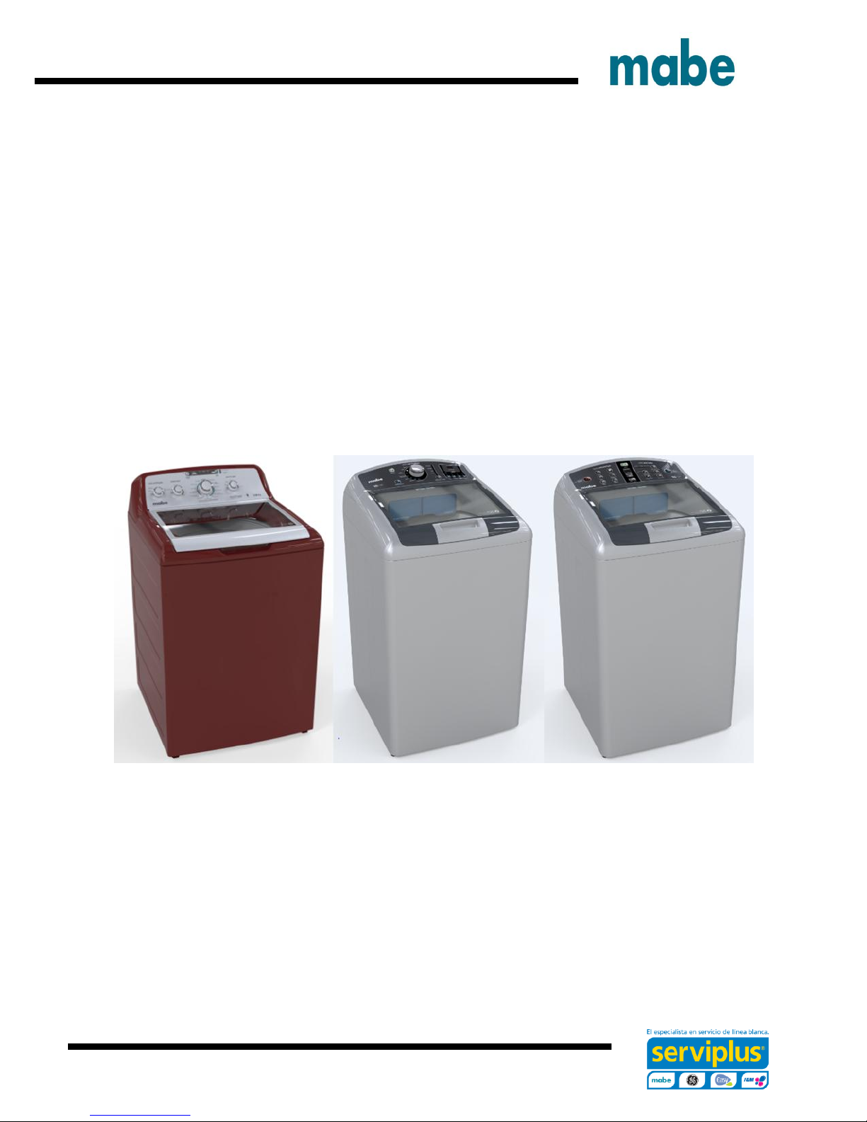
Top Load Washer Kraken 27”
HTW200BMKWW GTW460BMKWW
MTW200BMKWW GTW485BMKWS
GTW220BMKWW GTW680BMKWS
GTW330BMKWW GTW680BMKDG
GTW465BMKWS
Ingeniería de Servicio
- 2 -
IMPORTANT SAFETY NOTICE
IMPORTANT SAFETY NOTICE
The information in this presentation is intended for use by individuals
possessing adequate backgrounds of electrical, electronic, & mechanical
experience. Any attempt to repair a major appliance may result in personal
injury & property damage. The manufacturer or seller cannot be
responsible for the interpretation of this information, nor can it assume any
liability in connection with its use.
WARNING
To avoid personal injury, disconnect power before servicing this
product. If electrical power is required for diagnosis or test purposes,
disconnect the power immediately after performing the necessary
checks.
RECONNECT ALL GROUNDING DEVICES
If grounding wires, screws, straps, clips, nuts or washers used to complete
a path to ground are removed for service, they must be returned to their
original position & properly fastened.
Mabe authorized Service Technicians are required to use the Personal
Protection Equipment (PPE) listed below, for your own protection.
Ingeniería de Servicio

- 3 -
Dyneema® Cut Resistant Glove
Cut Resistant Sleeve(s)
Steel Toe Work Boot
Brazing Glasses
Plano Type Safety Glasses
Prescription Safety
Glasses
Safety Glasses must be
ANSI Z87.1-2003
compliant
Electrically Rated Glove and
Dyneema® Cut Resistant Glove
Keeper
Ingeniería de Servicio
- 4 -
CAUTION
Prior to disassembly of the Washer to access components,
Mabe authorized Service Technicians are REQUIRED to
follow the Lockout / Tagout (LOTO) 6 Step Process
Step 1
Plan and Prepare
Step 4
Apply LOTO device & Lock
Step 2
Shut down the appliance
Step 5
Control (discharge) stored
energy
Step 3
Isolate the appliance
Step 6
“Try It” Verify that the
appliance is locked out
Ingeniería de Servicio

- 5 -
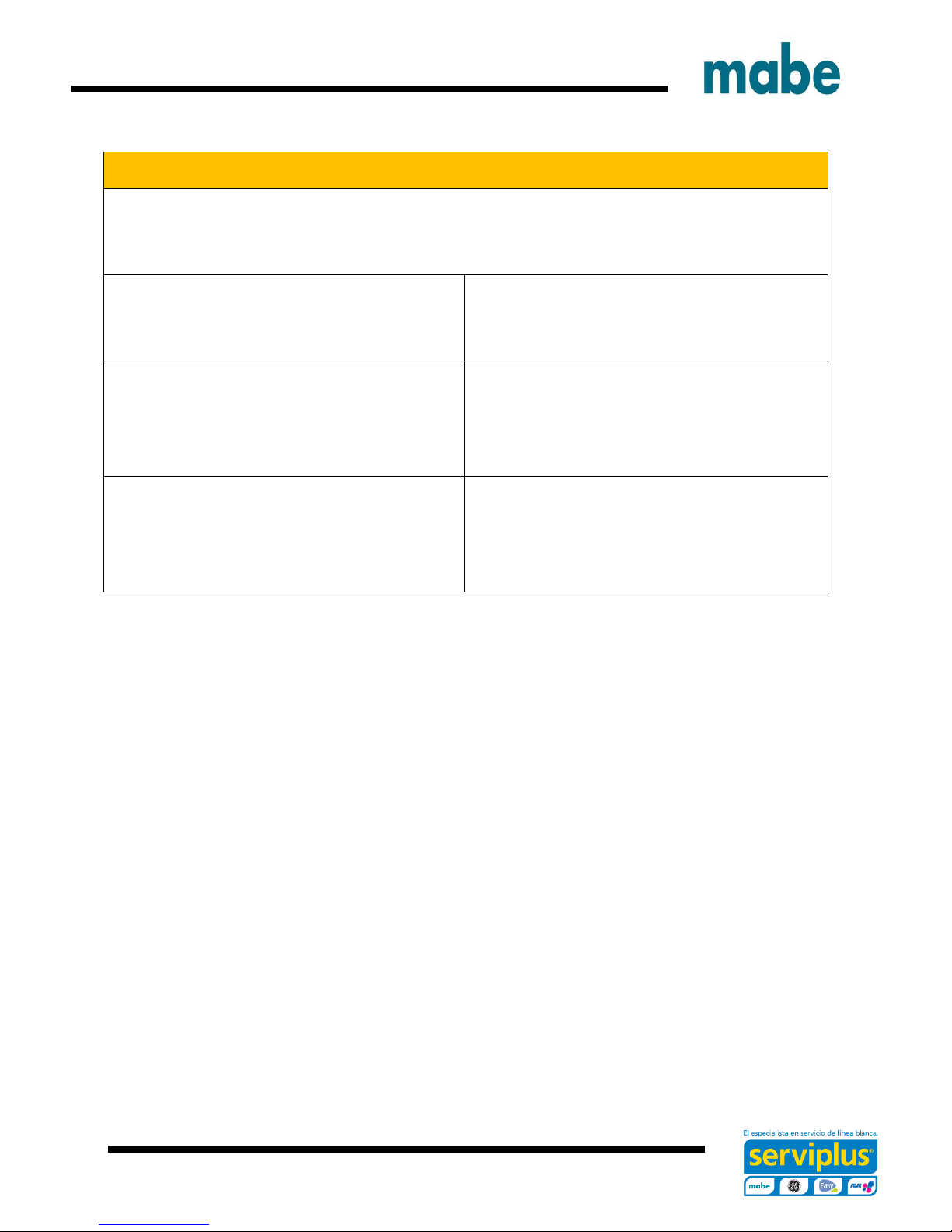
Some Features & Benefits
GTW460 Models
Deep Fill: Adds more water for larger
loads.
Dual-Action Agitator: Provide gentle,
dual-wash action.
Deep Rinse: Removes any leftover
soap residue.
Auto Soak: Loosens stains by soaking
up to 2 hours.
Speed Wash: Delivers ready-to-go
results within minutes.
Load Size: Automatically measures
load size, and adjusts settings and
water levels accordingly. Settings are
customizable, so you always get the
wash you want.
GTW680 Models
Sanitize with Oxi: Remove 99.9% of
bacteria with a dedicated cycle that
uses an Oxi additive to boost your
detergents cleaning power while
keeping fabric looking their best.
Stain Removal Guide: Assist removing
tough stains with preprogrammed
settings that modify your cycle to treat
the four most common stains.
Warm Rinse: Just what the consumer
ordered. The option to select between
a warm or cold rinse.
Deep Fill: Adds more water for larger
loads.
Deep Rinse: Removes any leftover
soap residue.
Auto Soak: Loosens stains by soaking
up to 2 hours.
Ingeniería de Servicio
- 6 -
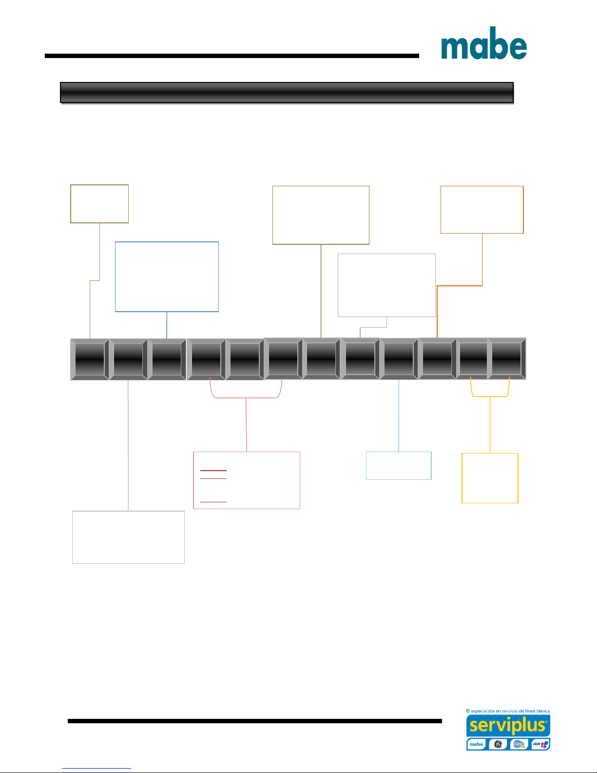
T
W
6
8
B
M
K
W
Brand
G = GE
H = Hot Point
M = Moffatt
Configuration:
F = Front Load
T = Top Load – Rear Control
N = Top Load – Front Control
U = Unitized
Platform:
W = Washer
D = Vented Dryer – Std
V = Vented Dryer – Long
C = Condenser Dryer
H = Heat Pump
Z = Flat Back Dryer – Long
X = Flat Back Dryer - Std
Series 1, 2, 3:
Series 1 = 1-9
Series 2 = 1-9
4 = 24” unitized
7 = 27” unitized
Series 3 = 1-9 Washer only
Partner Type
P = Premium Cost (color)
H = Home Depot
L = Lowes
S = Standard
C = Contract (Hoses)
M = Mabe
Year:
K = 2016
Engineering Number
0
1
2
Color:
W
S
0
0
G
S
Product Type
R = Riser
A = 2” Cover Top Load
B = 4” Cover Top Load
S = Standard / Stationary
P = Portable
Nomenclature
The nomenclature breaks down and explains what the letters and numbers mean in the model
number
Seguridad Advertencias y
Ingeniería de Servicio
- 7 -
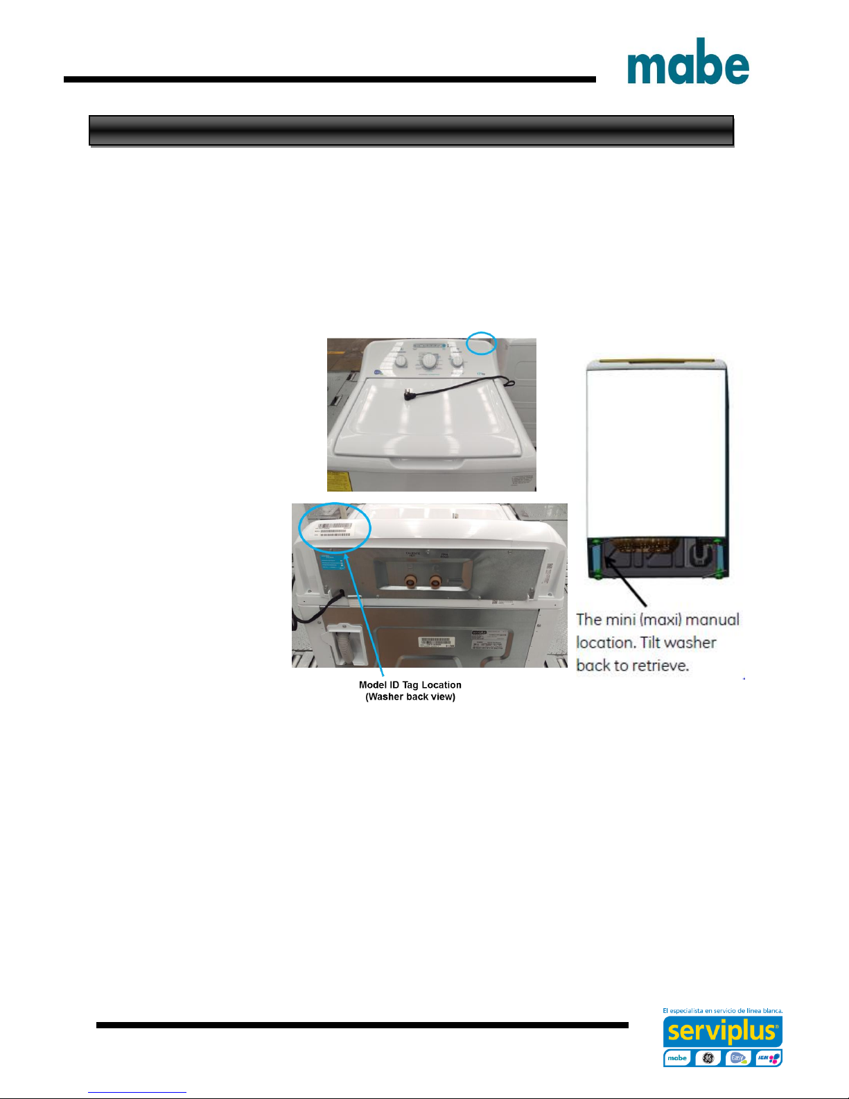
Serial Number and Mini Manual Location
Serial Number
The Serial Number breaks down and explains what the letters and numbers mean in its
structure:
Example of Serial Number: LG312345C
The first two characters of the serial number identify the month and year of manufacture: LG =
June, 2016
A = JAN A = 2013
D = FEB D = 2014
F = MAR F = 2015
G = APR G = 2016
H = MAY H = 2017
L = JUN L = 2018
M = JUL M = 2019
R = AUG R = 2020
S = SEP S = 2021
T = OCT T = 2022
V = NOV V = 2023
Z = DEC Z = 2024
The letter designating the year repeats every 12 years
The third character denotes the product being produced: 3 = Washer (Saltillo, Mexico)
Character 4 thru 8 will denote the number of units built for a given product and will start with
00001 at the beginning of each fiscal month and progress sequentially until 99,999 is
reached or the fiscal month has changed.
Character 9 will denote the Brand and Manufacturing site of final assembly: (Saltillo, Mexico:
C = GE, M = Signature, H = HPT)
The Model Serial ID Tag is located on the right top edge of the backsplash (left top edge from
back view).
The Mini Manual is in a storage bag inside the cabinet at bottom left side.
Ingeniería de Servicio

- 8 -
Water Levels
Approximate Minimum Water Levels
Impeller – 7 Gallons or 3 in. depth from
the bottom of the basket.
Agitator – 9 Gallons or 3-3/4 in. depth
from the bottom of the basket.
Test are completed with an empty basket.
Approximate Maximum Water Levels
Impeller – 26 Gallons or 13-1/2 in.
depth from the bottom of the basket.
Press and hold for 3 seconds “Deep
Fill” to achieve.
Impeller “Bulky” setting water level is
25 gallons or 12-3/4 in. depth from the
bottom of the basket.
Agitator – 26 Gallons or 12-1/2 in.
depth from the bottom of the basket.
Set to super.
Ingeniería de Servicio
- 9 -
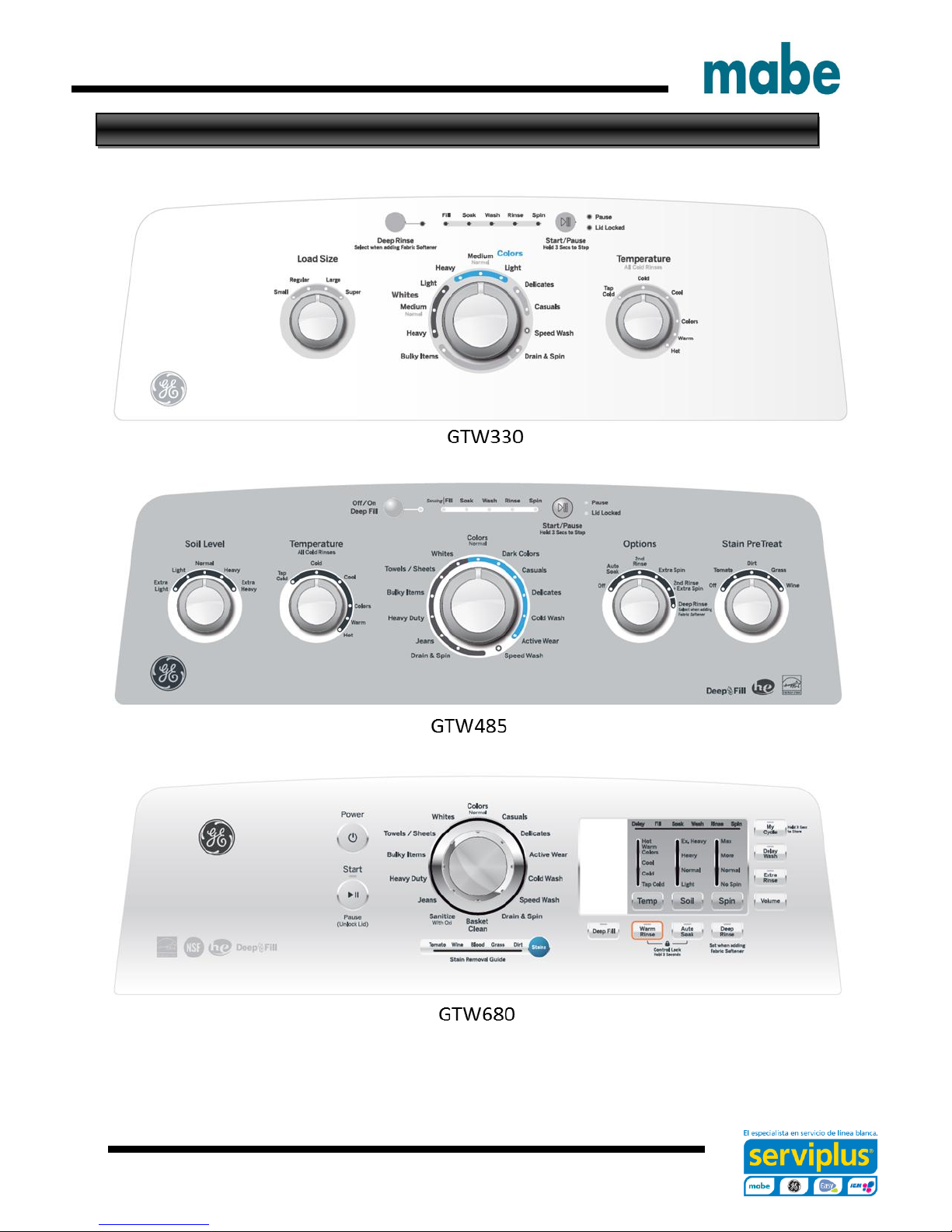
Model Graphics
Ingeniería de Servicio
- 10 -
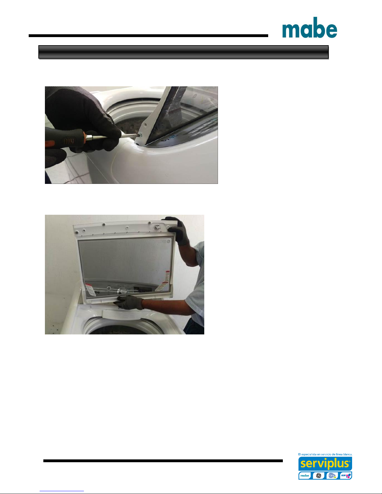
Lid Assembly Removal
Remove the two Philips head
screws of one Hinge (Right or Left
side).
Slide the lid toward the Hinge
Removed and lift it up to remove
Ingeniería de Servicio
- 11 -
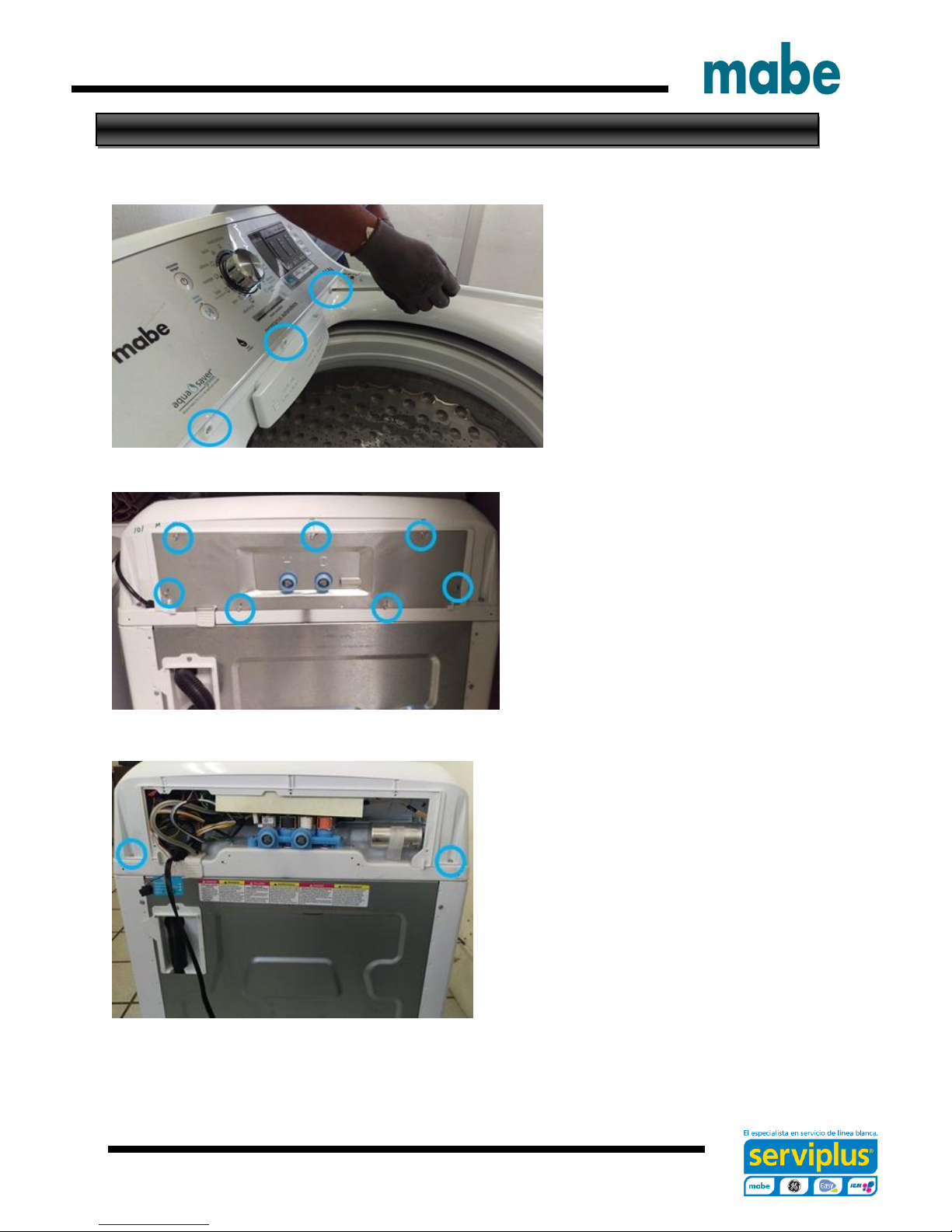
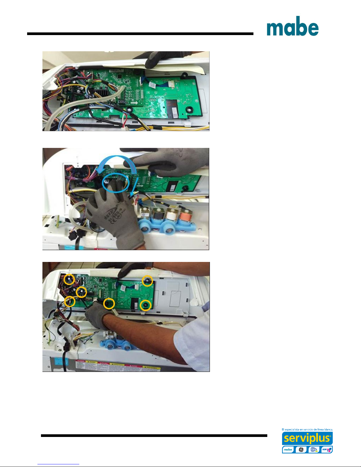
Control Panel Assembly Removal
To remove the control panel assembly, first remove the lid assembly.
Remove the three Philips head
screws that secure the control
panel assembly to the top cover
at front.
Remove the seven ¼ in. hex head
screws from the back panel and
remove it.
Remove the two ¼ in. hex head screws
from the rear corners on the control panel
IMPORTANT.- Do not move the control panel until disengaging the pressure tube from
the control board, otherwise the pressure sensor could be damaged.
Ingeniería de Servicio
- 12 -
Grasp the control panel and
push it a little toward the front of
the washer in order to see the
pressure tube.
To disengage the pressure tube
from the control board, grasp the
tube where it connects to the
pressure sensor on the board.
Twist the tube while pulling it off
the sensor
IMPORTANT.- Pressure tube
should not be handled vertically
or horizontally as there is a risk
of damage to the pressure
switch, only must disengage as
indicated above.
Disconnect connectors from the
control board and remove six ¼
in. hex screws securing the
control board bracket to the
control panel assembly and
remove.
IMPORTANT.- When reinstalling the control panel assembly, ensure that all ground
wires are reconnected and tested for proper continuity to the ground terminal on the
power cord.
Ingeniería de Servicio
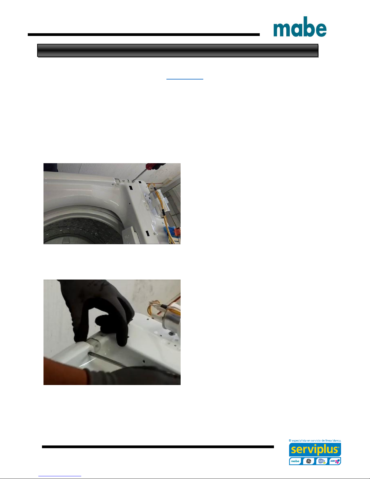
- 13 -
Lid Hinge
Video Link
Hinge removal can be achieved without removing the top cover or disconnecting the
control panel assembly completely.
Remove the lid assembly.
Disengage the control panel from the top cover and slide toward the rear to expose the
hinge mounting screws.
Remove the two ¼ in. hex head hinge
mounting assembly screws
Remove the Philips head screw from the
top cover.
Ingeniería de Servicio
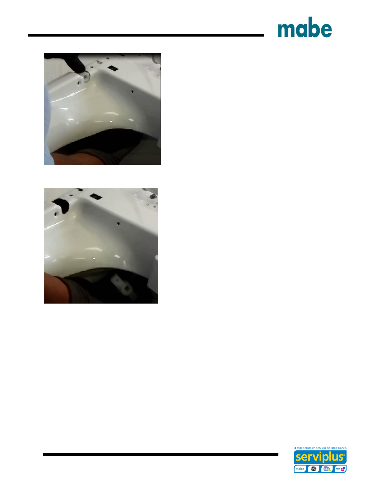
- 14 -
Slide a hand between the tub cover and the top
cover.
Grasp the hinge assembly and remove it from
under the top cover.
Ingeniería de Servicio
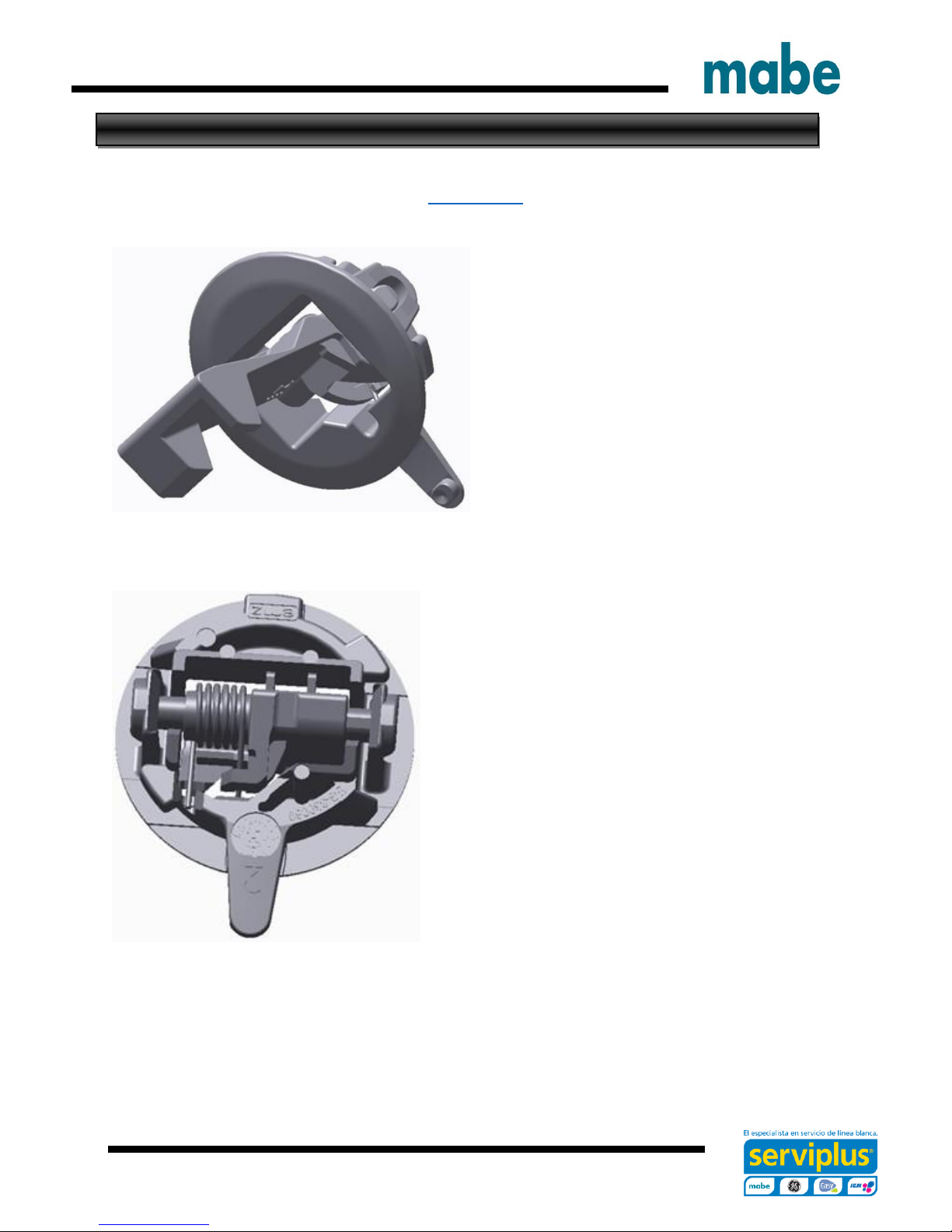
- 15 -
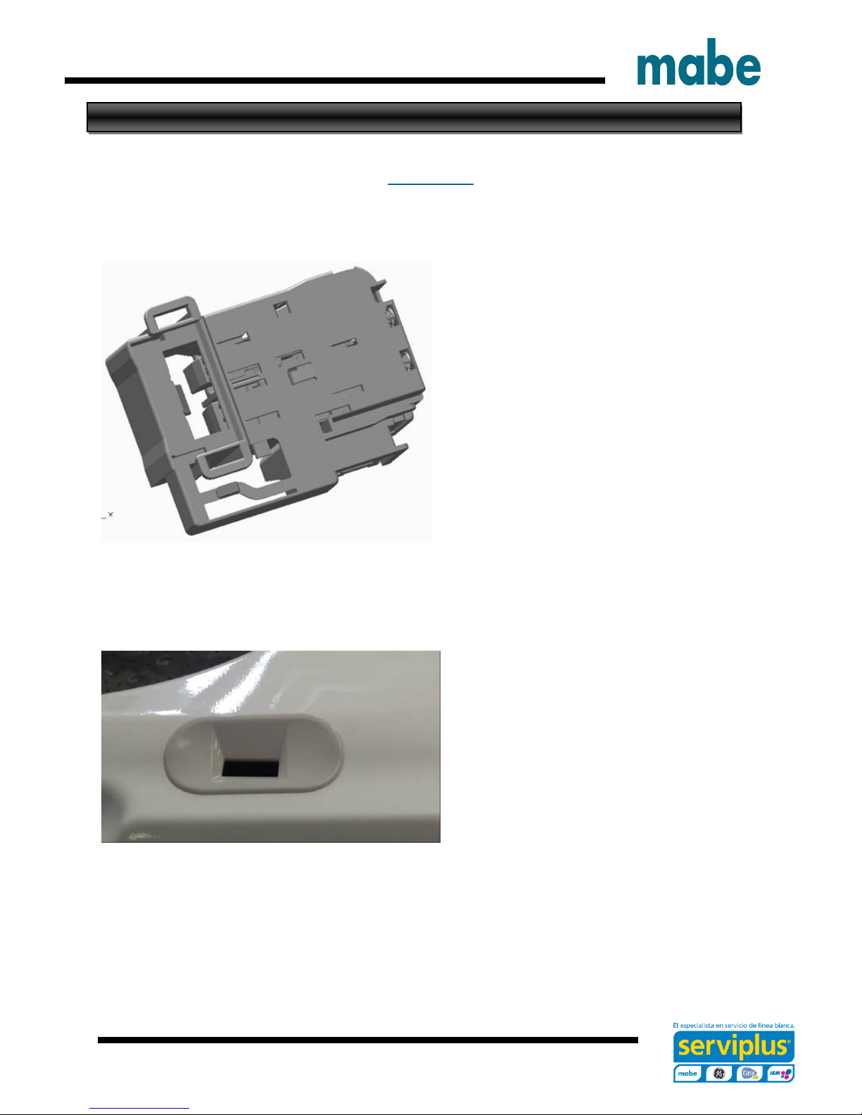
Lid Lock Striker
Video Link
The lid lock striker slides into the lid
lock/switch assembly. When a cycle is
started the lock assembly engages with
the striker preventing the lid from opening
during the cycle.
The latch has spring tension on it to keep it
engaged with the switch/lock assembly
Ingeniería de Servicio
- 16 -
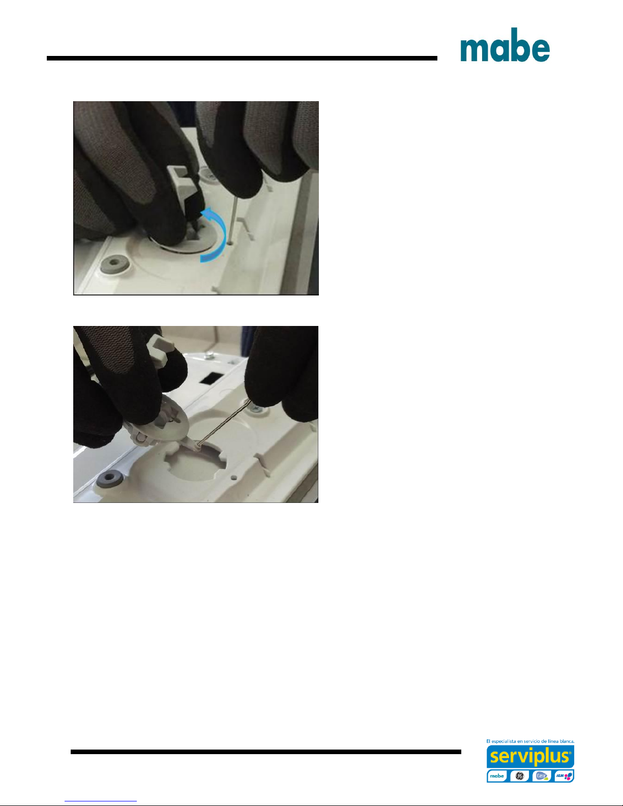
To remove the striker from the lid:
Open the lid.
Using a small screwdriver, insert it into
the small hole below the striker.
Push inward gently on the locking tab
and turn the striker to the left
Pull the striker from the lid
Ingeniería de Servicio
- 17 -
Lid Switch/Lock Assembly
Video Link
The lid lock and switch are together in
one part. It requires 120 VAC to activate
the lock.
The approximate resistance of the lock
coil is 70 ohm from Blue – Black from
J513 board connector (at Lid Lock closed
position)
Checking between Black and White wires
at the same board connector will show the
continuity of the lid switch.
To remove the lid switch/lock assembly:
Ingeniería de Servicio
- 18 -
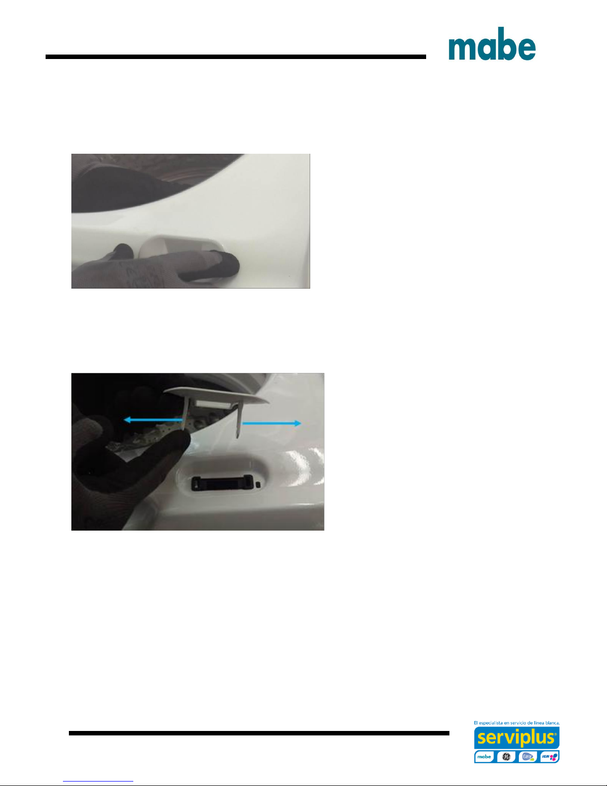
Remove the bezel from the top cover by
reaching under the top cover toward the
lock assembly and feel for the bezel tabs
to extend through the lock body.
Push the tabs out from the side of the
lock body and then push up to
remove the bezel from the top cover
Ingeniería de Servicio
- 19 -
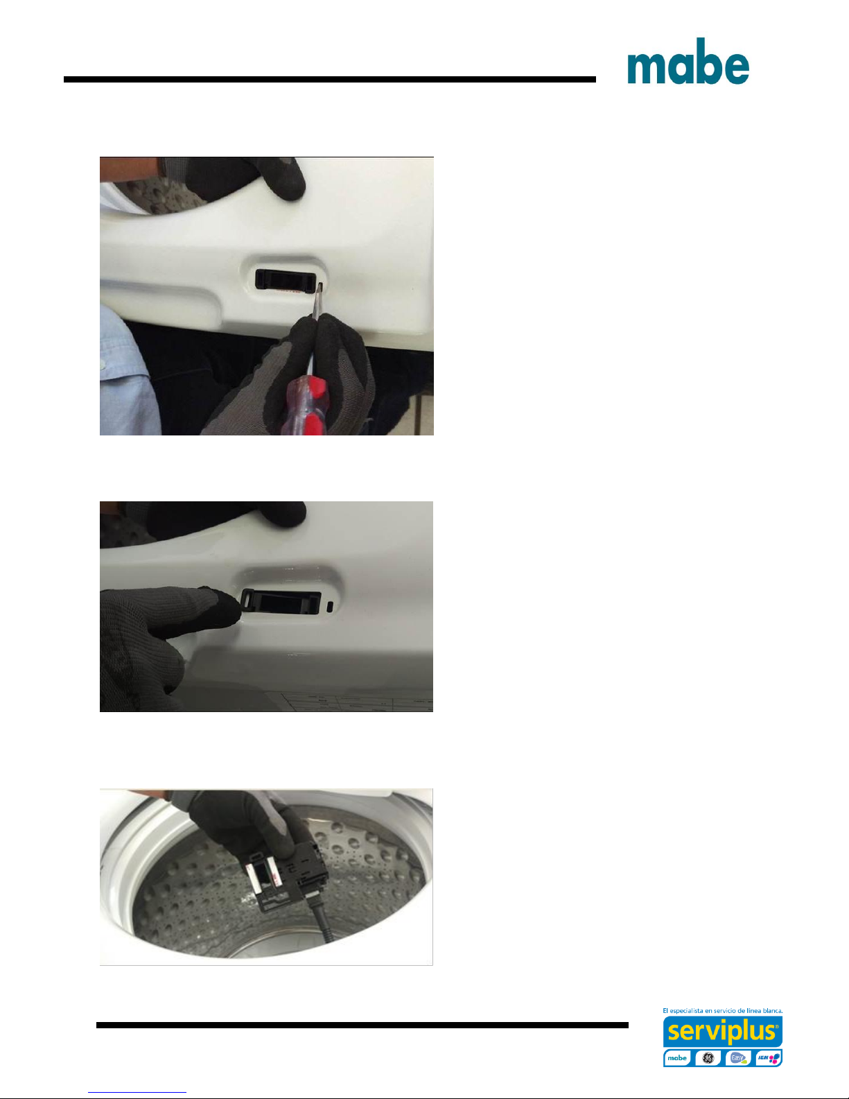
Using a small screwdriver, push down
gently on the tab that prevents the lock
assembly from sliding.
Slide the lock assembly to the left first to
disengage the right tab, then slide to the
right allowing the lock assembly
disengage from the top cover.
Pull the lock assembly from under the
top cover and disconnect the harness
connector.
Ingeniería de Servicio

- 20 -
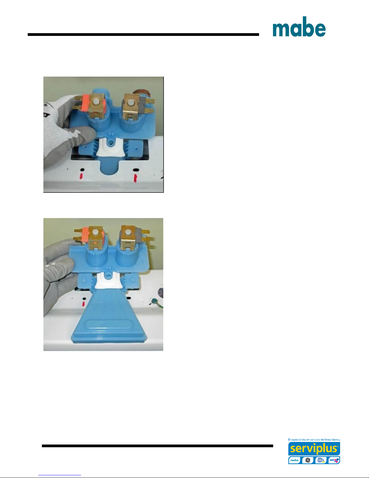
Two Coil Water Valve
Turn water supply off to valve. Hoses do
not need to be disconnected at this time.
Remove two Phillips head screws that go
through the thermistor mounting bracket
into the body of the valve.
Remove thermistor by pulling up on lip of
thermistor. Ensure o-ring is removed with
thermistor.
Ingeniería de Servicio
- 21 -
Tilt back of valve up and slide out of top cover.
Once valve is out and held over the basket,
disconnect hoses.
Valve, funnel and Gasket are one part.
Ingeniería de Servicio
- 22 -
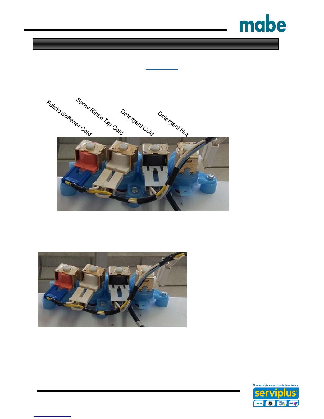
Four Coil Water Valve On GTW680 Model
Video Link
To remove the water valve:
Shut off the water supply to the
washer. Hoses do not need to be
disconnected at this time.
Lean the control panel assembly
back. It does not have to be
completely removed.
Disconnect the harness from the
water valve.
Ingeniería de Servicio
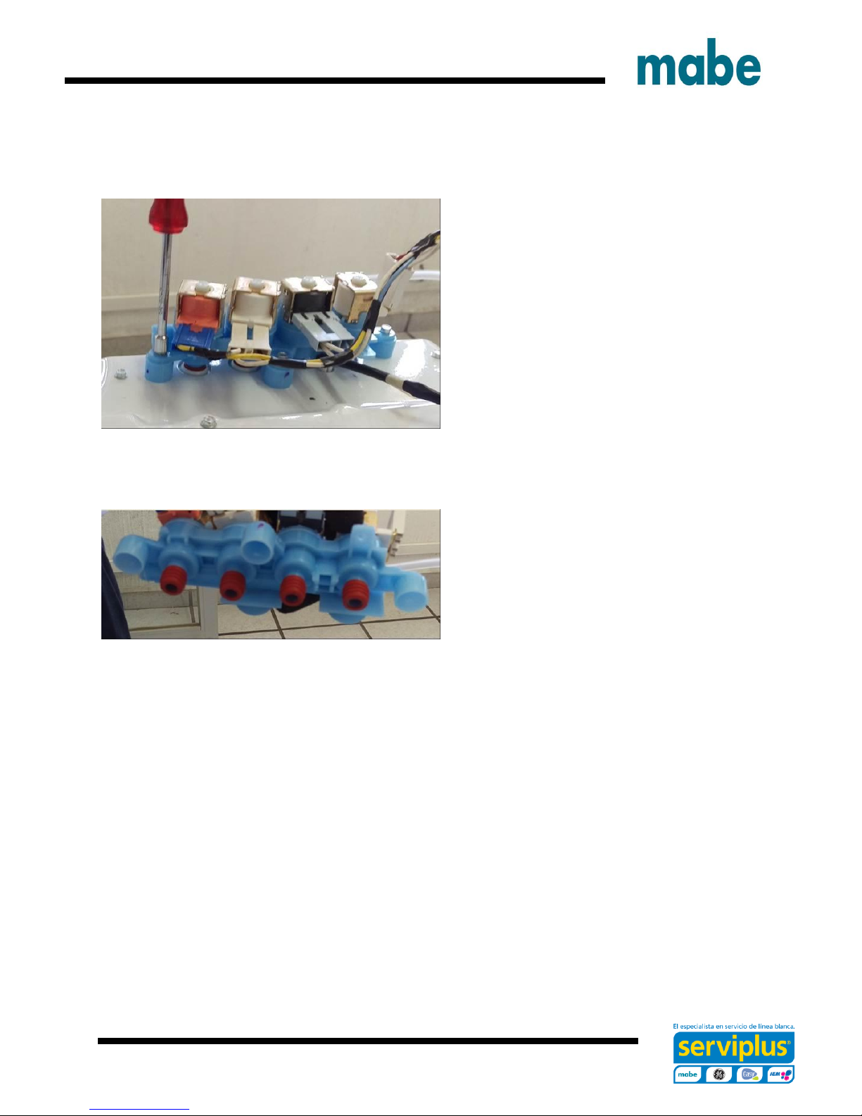
- 23 -
Remove three ¼ in. hex head screws
securing the valve to the top cover and
pull the valve up.
Hold valve over the basket and
disconnect the supply hoses from the
valve.
Quad Valve and the four rubber seals
are together in the same part number
Ingeniería de Servicio
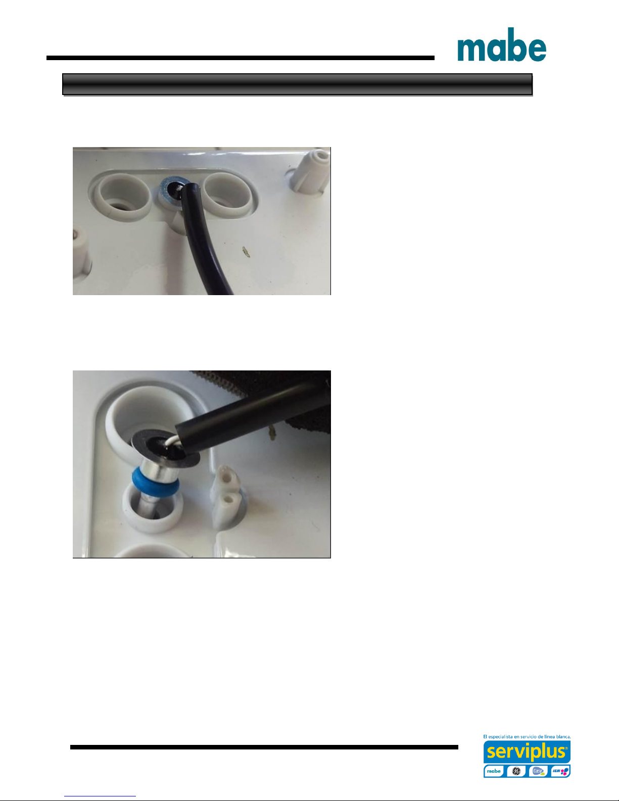
- 24 -
Thermistor Removal
After the water valve is removed, the
thermistor can be accessed and
remove.
It is pushed into the dispenser box
and held in place by the water valve
and is sealed with an O-ring.
Remove thermistor by pulling up on
lip of thermistor. Ensure O-ring is
removed with the thermistor.
Ingeniería de Servicio
- 25 -
Dispenser Removal
The dispenser hold detergent and
fabric softener and delivers it at
precise times for the cycle selected.
Water is added to the dispenser from
the water valve to fill and flush the
cups. After the valve turns off the
remaining water in the cup siphons
out.
Video Link
When bleach is added to the bleach
cup it is funneled through to the tub
cover and into the tub.
Remove the backsplash assembly,
water valve and top cover.
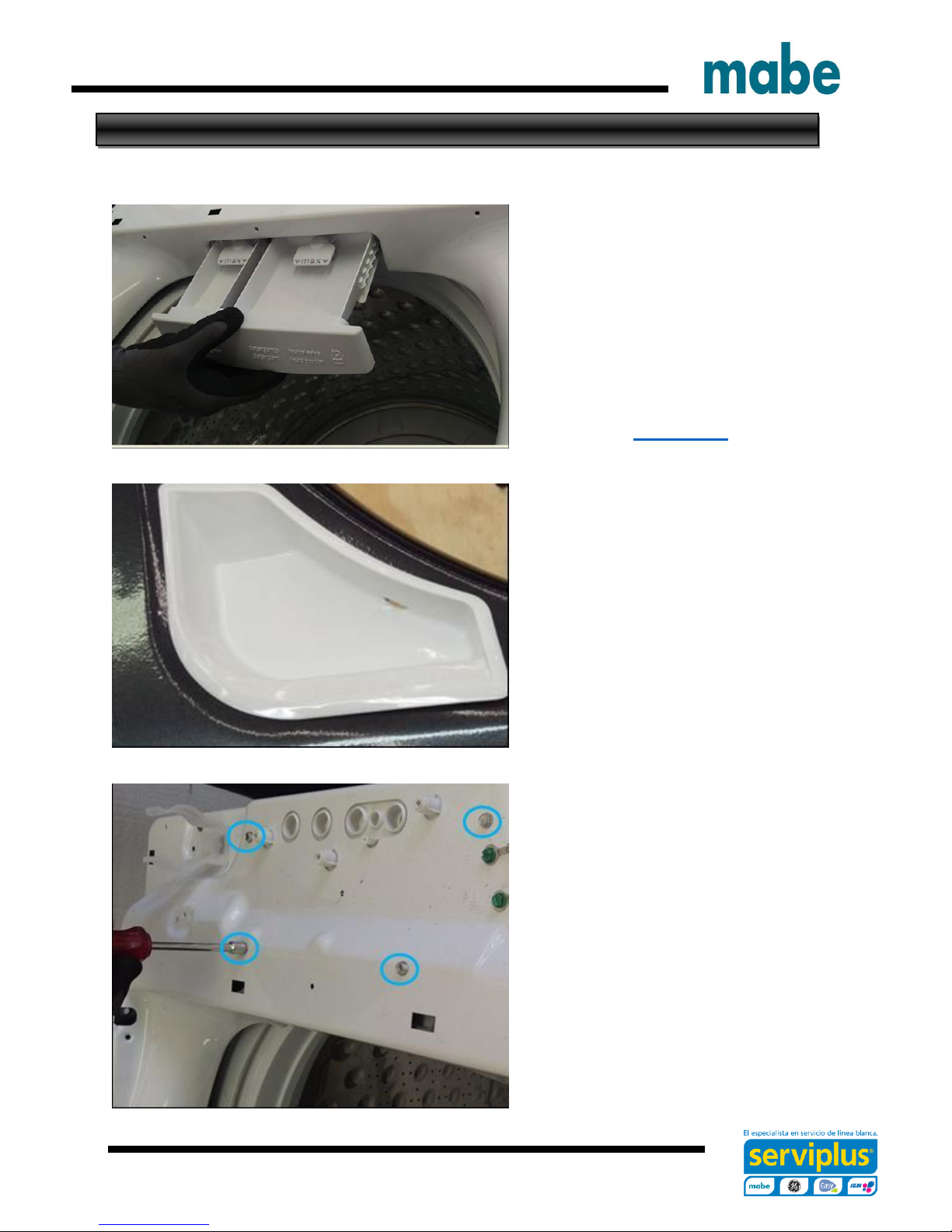
Remove the dispenser tray from the
dispenser body.
Remove four ¼ in. hex head screws
from the top cover securing the
dispenser body to the top cover
Ingeniería de Servicio
- 26 -
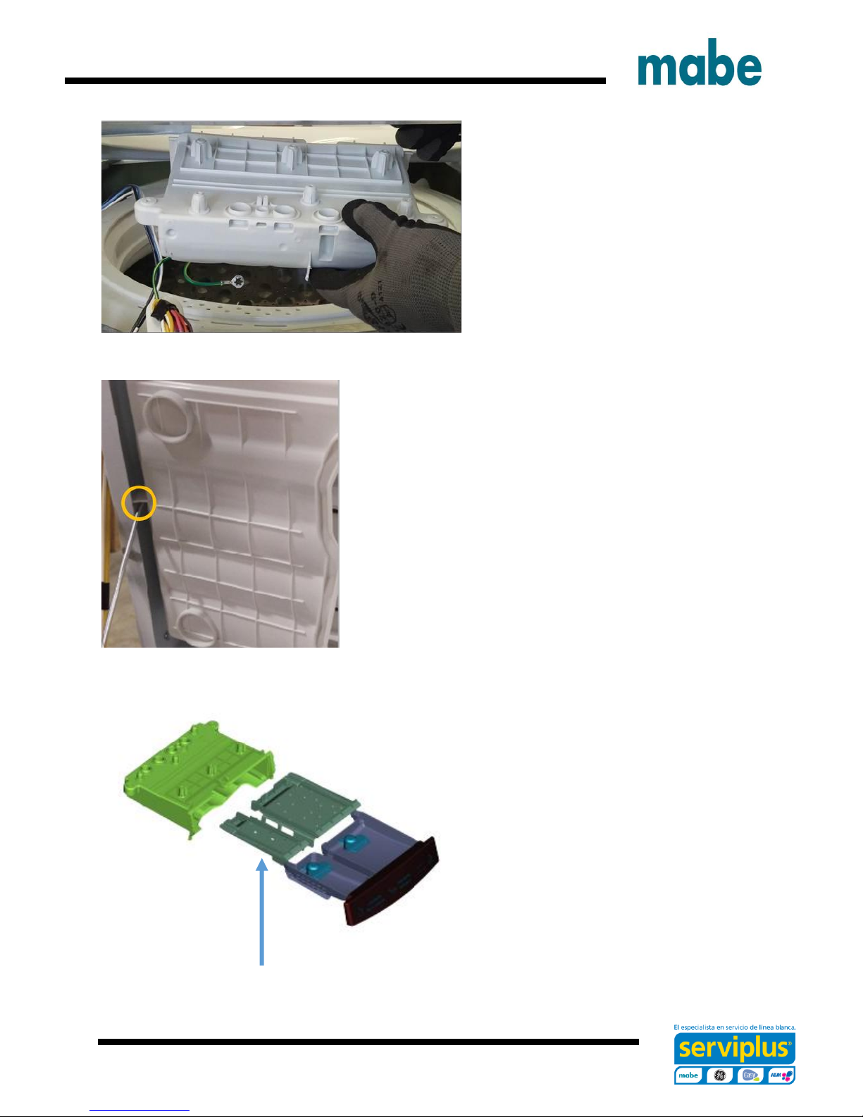
Dispenser Shower Insert
Remove the dispenser body from the
top cover by pushing back slightly on
the dispenser body and pull away
from top cover.
Take care of the back tap of the dispenser body in
order to not damage it.
The dispenser shower insert can be
removed at this time for cleaning if
necessary.
Ingeniería de Servicio

- 27 -
Top Cover Removal
Remove the lid assembly and control panel assembly.
.
Disengage the power cord from the top
cover by pulling up on the front of the
power cord grommet.
Slide the power cord grommet forward
Ingeniería de Servicio
 Loading...