

mabe PSS21 Series, GSS21 Series, GSS23 Series, GSS25 Series, GSS27 Series Service Manual
...
Training services to Mabe Consumer home
Service Manual
MODEL SERIES:
PSS and GSS
21, 23, 25, 27 and 29 cubic feet
PUB # 31-9072-SP 01/0

IMPORTANT SECURITY NOTICE
The information in this service guide is intended to be used by
persons having adequate background with electrical, electronic and
mechanical experience. Any attempt to repair a large device can
result in personal injury and damage to the property. Manufacturer
or seller cannot be responsible for the interpretation of this
information, nor can take any duty in relationship with its use.
CARE
To prevent personal injury, disconnect power before servicing
this product. If electric power for purposes of diagnosis or test is
required, disconnect power immediately after making the
necessary check-ups.
RECONNECT ALL DEVICES TO LAND
If you wire them, screws, belts, fasteners, or nuts, the grounding,
used to complete a pass to earth are removed for service, should
be returned to his position original and adjusted properly.
Entrenamiento de Servicios a Domicilio del Consumidor de GE
Guía Técnica de Servicio
Copyright © 2001
Todos los derechos reservados. Esta guía de servicio no puede ser reproducida total o
parcialmente en ninguna forma, sin el permiso escrito de la General Electric Company.
!

- 1 -
INDEX
Introduction
Installation
Specifications
Nomenclature
Operation characteristics
General views of localization
Mechanical disassembly
Diagnostics
Views of localization of components
and connector
Diagrams
Catalogs illustrated parts
. . . . . . . . . . . . . . . . . . . . . . .
2
. . . . . . . . . . . . . . . . . . . . . . .
3
. . . . . . . . . . . . . . . . . . . . . . .
4
. . . . . . . . . . . . . . . . . . . . . . .
5
. . . . . . . . . . . . . . . . . . . . . . .
6
. . . . . . . . . . . . . . . . . . . . . . .
13
. . . . . . . . . . . . . . . . . . . . . . .
15
. . . . . . . . . . . . . . . . . . . . . . .
29
. . . . . . . . . . . . . . . . . . . . . . .
52
. . . . . . . . . . . . . . . . . . . . . . .
59
. . . . . . . . . . . . . . . . . . . . . . .
60
- 2 -
Introduction
2001 SxS Energy models are being introduced in response to
the requirements of more energy-efficient refrigerators by mid2001, along with improvements in features and operation. The
primary differences in this cooling system are the defrosting
adaptable system (watch Pub # 31-9062), control board,
software, and systems control that operate regardless in the
sections of the cooler and freezer. The new high-efficiency
control system has the ability of cycling components and
adjusting the fan speeds as required, to maintain the
temperature adjustment ranges in the cooler and freezer
sections. The feedback systems are digital inputs and relay
outputs. The sensors (thermistors) are used to measure the
temperature with communication to the main board, which
controls the components of the unity.
The refrigerator has key controls to give inputs to the
microprocessor. The cooler and freezer controls are of the
temperature control point type and have settings of 0-9 with 9
being the coldest possible temperature. The new NONCLEAN condenser is repairable from the back and is designed
to prevent the customer from having to
clean the condenser in conditional normal use.
The sealed operation system and the compressor are working
in the same way as the previous models, with some minor
changes.
The collateral models Profile Performance and Arctica are
the affected models. These models are available with cold
water through the door and ice dispenser, and a water filter
detail that can be filled. In models that require an ice
machine, the new electronic ice machine model (see Pub. #
31.09063) has been or can be installed.
The freezer has built-in grills, a spill-proof grill that pulls out,
an Easy Space grill, deep door grills, based on the model. The
chiller section has a Baking Soda holder, a fruit and vegetable
drawer, drawer dividers, and a moisture-adjustable drawer
and a convertible meat drawer.
The new high-efficiency refrigerator is a combination of the
most efficient refrigeration systems and the most desirable
customer details available.
- 3 -
METODO
PREFERIDO
ASEGURESE QUE EXISTE
ADECUADA PUESTA A
TIERRA ANTES DE USAR
ETODO TEMPORAL
(En Canadá no se permiten
daptadores de enchufe)
ASEGURE ADECUADA
PUESTA A TIERRA Y
CONEXION FIRME
ANTES DE USAR
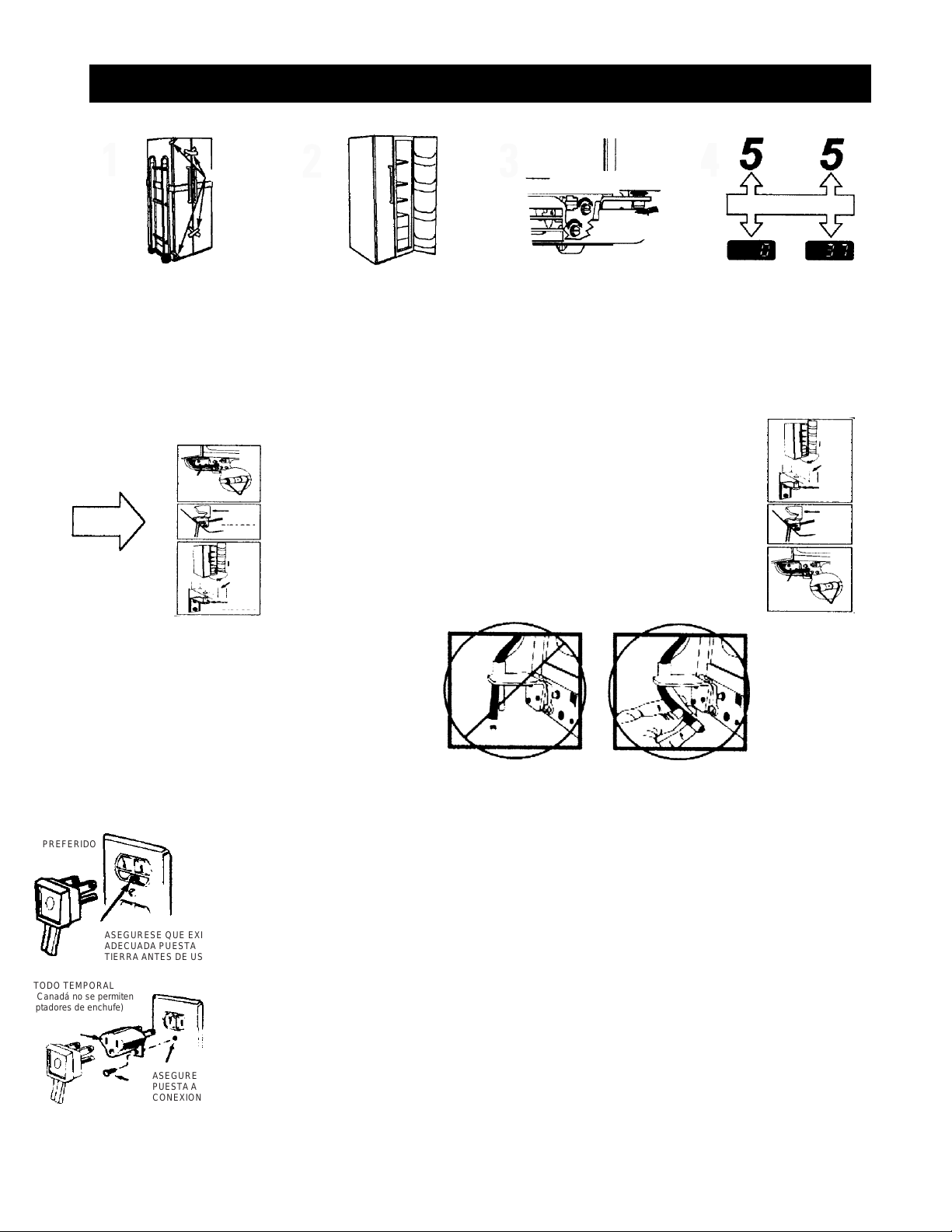
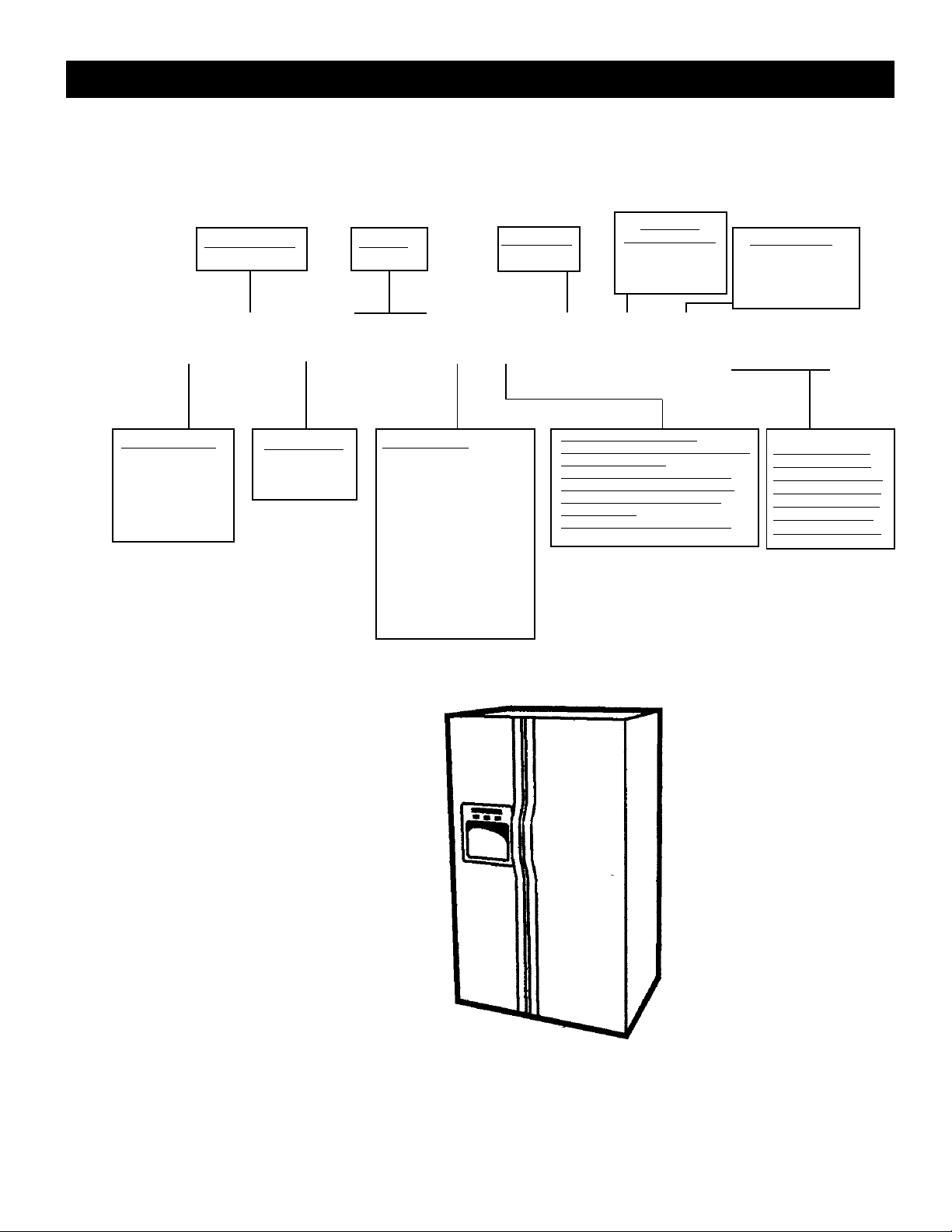
Installation
Tape
Use a cushioned hand truck to protect the
finished refrigerator. LEAVE
THE TAPE IN THE DOORS until it is in its
final location. LOAD ONLY FROM THE
SIDE. Avoid tighten the belt a lot to avoid
damage of the doors
REMOVE ALL THE PROTECTOR
TAPE FROM THE SURFACE, then
move the unit to its position. If the inlet
is less than 38" wide, remove the doors
before installation and reinstall them
according to the pro- bottom down.
Connect the water lines and the electric
cord. ADJUST THE FRONT ROLLS so
that the refrigerator is firm on the floor
and the doors close easily. MAKE SURE
THE DOORS ARE COUPLES ABOVE.
TEMPERATURE CONTROLS ARE
PRESCRIBED IN THE FACTORY
FOR RE-COMBUSED ADJUSTMENT
REMOVING THE DOORS
The doors must be in closed position.
Near the bottom hinge on the freezer side, tighten
the collar on the water line and pull the tubing from
the coupling. Also, disconnect the wiring from the
wire. Pull the water line and wiring through the
bottom rail.
Remove the covers of the upper hinges to access
the hinges. Remove the hinges using a Torx T-20.
Carefully turn the door by 90 °. Guiding the water
line and wiring the fence, lift the door straight up.
Avoid loading the lower hinges sideways. Place the
doors on a protected surface. Avoid piercing the
water pipe and wiring the wiring in the bottom of the
door.
With the doors open at 90 °, place them on the lower
hinge. Carefully turn the doors to the closed position.
Avoid loading the lower hinges sideways.
Reinstall the upper hinges and tighten the screws
firmly. Reinstall the hinge cover. If the doors are not
level, adjust the lower right hinges with a 7/16 open
end wrench.
Insert the water pipe back into the coupler. It is fully
connected when the mark on the pipe is no longer
visible. Reconnect the wiring of the wiring. Open the
water supply.
CABLEADO
ALAMB.
PUERTA
SUJET.
BISAGRA
CUBIERTA
BISAGRA
REBORD
CABL.
REBORDES
CUBIERTA
PUERTA
SUJT.
AJUSTE ALTURA
RODILLO
AJUSTE ALTURA PUERTA
CONTROLS ADJUSTMENTS
REINSTALLING THE DOORS
• HEET WAX IS RECOMMENDED TO REMOVE TAPE WASTE AND HAND FINGER FROM THE REFRIGERATOR OUTSIDE.
• REMOVE ALL TAPE AND PACKAGING MATERIAL FROM INSIDE REFRIGERATOR. DO NOT REMOVE THE SERIAL PLATE.
• REMOVE THE PROTECTIVE FILM ON THE TEMPERATURE CONTROL PANEL.
IMPORTANT: PLEASE READ CAREFULLY
FOR PERSONAL SAFETY, THIS APPLIANCE MUST BE ADEQUATELY GROUNDED
The power cord of this appliance is equipped with a three-prong (grounded) connector that fits a three-pronged (grounded)
standard receiver to minimize the risk of an electrical hazard to this appliance. The customer should check the wall receiver and
the circuit by a qualified electrician to make sure that the appliance is properly grounded.
Where a standard two-pronged wall receiver is located, it is the customer's responsibility and personal obligation to exchange it
for a properly grounded three-prong wall receptacle.
NDER NO CIRCUMSTANCES, CUT OR REMOVE THE THIRD POINT OF THE (EARTH) CONNECTOR FROM THE ENERGY
CORD. SITUATIONS OF USE IN WHICH THE ELECTRICAL CORD OF THE APPLIANCE WILL BE DISCONNECTED
INFRECTIVELY
Due to potential safety hazards under certain conditions, we strongly recommend against the use of an adapter plug. Without
em However, if you always choose to use an adapter where local codes permit, a TEMPORARY CONNECTION can be made to a
properly grounded two-prong wall receptacle approved by the UL adapter list which is available in most of the hardware stores.
The largest hole in the adapter must be aligned to give an appropriate polarity in the power cord connection.
to CAUTION: Connecting the terminal of the grounding adapter to the screw cover of the wall receiver does not ground
the device, unless the cover of the screw is made of metal, and is not insulated and the receiver of the wall is grounded through
the wiring of the house. The customer must check the circuit by a qualified electrician to make sure the receiver is properly
grounded. When disconnecting the power cord from the adapter, always hold the adapter with one hand. If you do not do this,
the terminal of the ground adapter is very safe to break with repeated use. If this happens, DO NOT use the appliance until a
ground connection has beenestablished
SITUATIONS OF USE IN WHICH THE ELECTRICAL CORD OF THE APPLIANCE WILL BE DISCONNECTED FREQUENTLY
Do not use an adapter plug in these situations because frequently disconnecting the power cord places undue stress on the
adapter and leads to eventual failure of the adapter terminal to ground. The customer must change the two-pronged receiver
on the wall for a receiver
Three-prong (grounded) by a qualified electrician before using the appliance.
ELECTRIC SPECIFICATIONS
Temperature control………………………
Relay……………………………..…….....
Overload .................................................
Capacitor Func. (12 uF) .........................
Thermostat Overtemperature ................... Wiring
Wiring & Thermostat heat defrost .....
Heater Discong. & Clamp ..........
Fan Motor Condenser .....................
Fan Evaporator Engine ........................
Main Board ..................... ...................
Dispenser Board ..................................
Thermistor (EV) ............................................
Thermistor (FZ) ............................................
Thermistor (FF) ............................................
Thermistor (FF) ............................................
Fans Fan Motor ........................................
Shock absorber……………………………
wr55x10023
wr07x10031
wr08x10025
wr62x10079
wr50x10015
wr23x10142
wr51x10030
wr60x10042
wr60x10043
wr55x10024
wr55x10029
wr55x10025
wr55x10026
wr55x10027
wr55x10028
wr60x10051
Specifications
DISCONNECT THE POWER CORD BEFORE
SERVICING. -IMPORTANT- CONNECT ALL
EARTHED APPLIANCES AGAIN
All parts of this device capable of conducting electrical
current are grounded. If the wires, bolts, fasteners,
fasteners, nuts and ground washers used to complete a
grounding are removed for service, they must be returned
to their original position and be properly tightened.
IMPORTANT SAFETY NOTICE
This information is intended to be used by people
who have an adequate background in electrical,
electronic and mechanical experience. Any
attempt to repair an appliance can result in
personal injury or property damage. The
manufacturer or seller cannot be responsible for
the interpretation of this information, nor can it
assume any responsibility in relation to its use.
ELECTRIC SPECIFICATIONS
Temperature Control (Position 5) ................
Defrosting Control ........................... …….
Thermostat Overtemperature ...................
Defrosting Thermistor………....................
Electric Capacity: 115V, AC 60 Hz .........
Maximum Current Leak .................. ……
Maximum Resistance to Earth ................
Energy consumption……………………..
OPERATION WITHOUT LOAD
MID / MID Control Position
and Environment of:
Refrigerator, ° F .................................
Freezer, ° F ................................. ….
Func. Time,% ....................................
REFRIGERATION SYSTEM
Refrigerant charge (R134a) ..................
Compressor……………………………...
Minimum Compressor Capacity ............
Minimum Equalized Pressure
@ 70 ° F .................................... ………
@ 90 ° F .................................................
7-(-11)°F
60 hrs @ 35 min
without door openings
140-110°F
65°F
11.6 Amp
0.50 mA.
0.14 Ohms
KWH/month
70°F 90°F
34-40 34-40
(-3) 3 (-3) 3
<45% <70%
4.75 onzas
690 BTU/hr
22 pulgadas
48 PSIG
60 PSIG
VOLUME
23/25/27/29
NOMENCLATURE
Profile Models 2001
P S S 2 5 I E M A F W W
Location of
the sheet
with
technical
information
(Remove the grid assembly
stuck under the cabinet)
- 5 -
INTERIOR/GRILL
D = Wire Deluxe I =
Vidrio Deluxe
J = Glass of first class
K = Glass against overflow
M = Glass against overflow/
Slides to the outside
Q = Derivative Exposure S =
Stainless Steel Doors U = ABV
Derivative V = Derivative
SEARS W = Derivative HPS
(Contract) X = Derivative
REGIONAL
PROF/ENERGY
S = ESTANDARD
T = TROPICAL
G = GLOBAL
BRAND/PRODUCT
G = GE
H = HOTPOINT
P = PROFILE (GE)
E = ETERNA (GE)
R = RCA
S = SELECT (GE)
ICE MACHINE / EXTERIOR
B = Not ready for dispenser / ice maker
D = Ice cubes / Water
E = Ice cubes and chopped / Water
F = Filter / ice cubes and chopped 6
months G = Filter / ice cubes and
chopped 1 year
i = Filter / Indicator & C / CW online
EXTERIOR COLOR
WW = White / White
AA = Almond / Almond
BB = Black / Black CC
= Bisque / Bisque WH
= White / Black BS =
Black / Stainless Steel
TYPE OF DOOR
F = Plane door (Line-
G) (ESPACIO = Door
Plane (S- & Línea-T)
K = Door of adjustment
YEAR MODEL
M = 2001
CONFIGURATION
S = Ref Door Col
DESIGN OF
NOMENCLATURE
A = INITIAL DESIGN
B = 1ST REVIEW.

Operation characteristics
INDEX
Independent Operation of the Cooler / Freezer
............................................... 7
Normal Operation Characteristics, but Different
of Previous Models ........................................................................................................ 7
Features Abnormal Operation (Incorrect Operation) ..................................................... 7
Adaptive Defrosting ....................................................................................................... 7
Cooling Operation (Adaptive Defrosting) ....................................................................... 8
Pre-Cooling Operation (Adaptive Defrosting)
Operation Heater Defrosting (Adaptive Disconnect)
............................... 8
.............................. 8
Rest Period (Adaptive Defrosting) ................................................................................. 8
Post Rest (Adaptive Defrosting) .................................................................................... 8
Liner Protection Mode ................................................................................................... 8
Electronic Ice Machine .................................................................................................. 9
Dispenser functions ....................................................................................................... 9
Fast Ice ....................................................................................................................... 9
Door Alarm
Dispenser Light
............................................................................................... 9
.............................................................................................. 9
Closing the Dispenser .................................................................................................. 9
Filters ............................................................................................................................. 10
Hinge and Door Closing System ................................................................................... 10
Air Flow (Cabinet Interior) ............................................................................................. 10
Condenser "JELLY ROLL"
Main Control Board
.................................................................................. 11
.................................................................................. 12

Independent Operation of the Refrigerator / Freezer
In previous models, the chiller and freezer compartment
components worked at the same time. When the cooler
compartment asked for cold air, the components of the
freezer compartment worked with the components of the
cooler compartment. This is called operation
no Independent.
In this model, the components of the compartment of
the cooler they can operate without the operation
of the components of the freezer compartment. This is called
independent operation.
Normal Operating Characteristics that may
Occur, but Different from Previous Models
• The ice machine's drill rotates in the direction of the
hands of the clock.
• The evaporator fan operates without the compressor or
condenser fan. Refrigerator fan is switched on.
• Post Rest (adaptive defrost), compressor fan and condenser
on with the evaporator fan off after the defrost cycle.
• Lining Protection Mode, fans come on when doors open
for 3 minutes.
• When the doors open, the fans turn off.
• There is no air flow to the cooler compartment when the
evaporator fan is on.
• The evaporator and compressor fan can operate
continuously for 8 hours.
• The fans change speeds, different levels of sound can be
noticed when this happens.
• Quick Ice Mode, the evaporator fan works for 48 hours
without stopping.
• Response time for drastic temperature changes is 2 to 10
minutes. The main control board will only respond to 8
degrees of temperature change per minute as determined by
the change of resistance of thesensor.
- 7 -
Abnormal Operation Characteristics (Incorrect
Operation)
• Cooler fan on and evaporator fan off.
• Evaporator fan on, cooler fan and compressor off,
and damper closed.
• Quick changes in fan speed, the fan takes at least 1
minute to change speeds.
• The compressor running without the condenser
fan. The compressor and condenser
fan forever must of functional to the same weather.
• The condenser fan running without the
compressor. The compressor and condenser fan
should always work at the same time.
Adaptive Defrosting
Adaptive defrosting can be described as a defrosting system
that adapts to the environment around the refrigerator and the
use of the home.
Unlike traditional defrosting systems that use
electromechanical timers with a
Fixed defrost cycle time, adaptive defrost uses intelligent
electronic control to determine when the defrosting cycle is
necessary. In order to achieve the correct defrosting time
cycle, the main control board monitors the following cooler
operations:
• Length of time when the refrigerator doors were
opened since the last defrost cycle.
• Length of time that the compressor has operated
since the last defrost cycle.
• Amount of time that the defrost heaters were on since
the last cycle of defrosting.
• Adaptive defrosting is divided into separate
cycles. These operations are:
• Cooling operation Pre-cooling
operation
• Defrosting Heater Operation Rest Period
• Post Break
See Pub # 31-9062 for more information on
Defrosting Adaptable
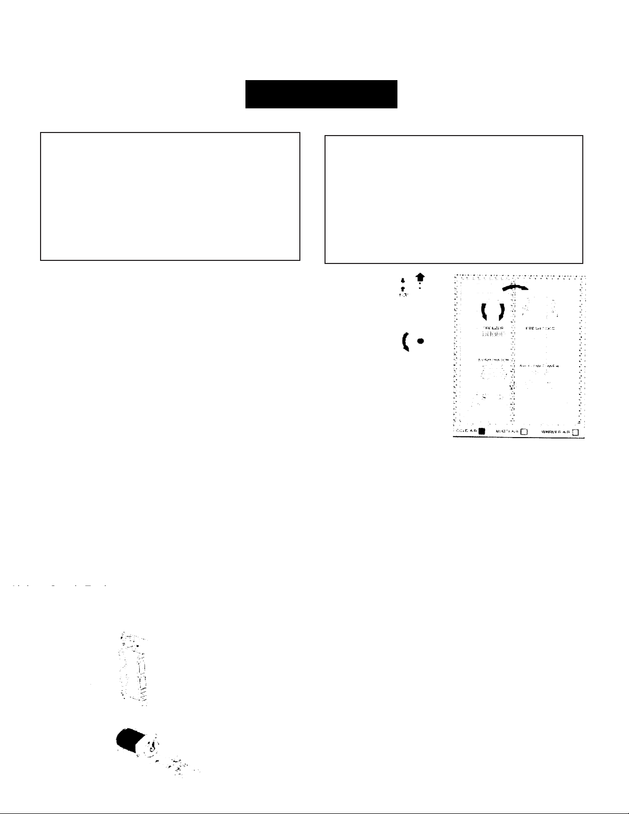
Cooling Operation (Defrosting Adaptable)
During the cooling operation, the main control board
monitors door openings (cooler and freezer doors) and
operating time of the compressor. The length of time
between consecutive defrosts is reduced by each open
door. If the doors are not opened, the compressor will
work up to 60 hours between defrosting. If the doors open
frequently and / or for long periods, the operating time of
the compressor between defrosting will be reduced to as
little as 8 hours
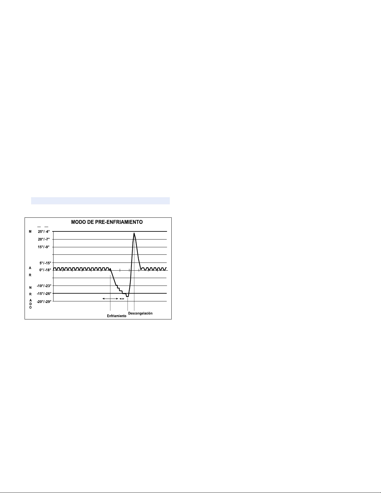
Pre-Cooling Operation (Defrosting
Adaptable)
When the main control board determines that the
defrosting is necessary, the main control board will force
the refrigerator to a continuous mode cooling (precooling). During pre-cooling, the freezer temperature can
be carried down the set point temperature of the control
panel screen. However, the temperature of the cooler will
be regulated by the shock absorber Pre-cooling and will
last 2 hours if it is not interrupted by some open door. If
after 8 hours, the unit could not complete a pre-cooling
without interrupting, the defrost cycle will continue.
Operation of the defrost heater
After 2 hours of pre-cooling operation or 8 hours of
interrupted pre-cooling attempts, the main control board turns
off the compressor, condenser fan and the evaporator
fan. The main control board then energizes the defrost relay,
which completes the Defrost Cycle.
A thermostat-defrosting (switch) protects the defrosting
system. The thermostat opens when the evaporator
temperature rises to 140 ° Fahrenheit and closes when the
evaporator temperature drops to 110 degrees Fahrenheit.
Rest Period (Adaptive Defrosting)
After the main control board has completed the operation of the
defrosting heater, there is a resting period of 5 minutes. During
this period, the compressor, condenser fan and evaporator fan
they stay off. Frost melting that remains of the evaporator will
continue to fall and drain to that the evaporator to be completely
clean of any humidity before the cooling operation. After 5
minutes of resting period, the unit enters a post break.
Post Rest (Adaptive Defrosting)
The post-rest period is designed to cool the evaporator before
circulating the air inside the refrigerator. This prevents any
residual heat in the evaporator from being distributed in the
freezer. During this period, the compressor and the condenser
fan are on, but all the interior fans are off and the shock
absorber is turned off. Post-rest times vary with the different
Models. However, there is a maximum of 5-minutes
of resting time.
Liner Protection Mode
The liner protection mode will be activated if any of the doors
have been opened for 3 minutes. This mode will start the fans
and will close the damper. This mode is controlled by 2
timers. Timer # 1 monitors door open time. A 3-minute open
count. The door will start when the door is opened. If it passes
3 minutes before the door is closed, the protection mode of
lining will be activated. Once the door is closed, timer # 1 is
reset and the liner protection mode passes to reserve. In
reserve, normal fan and damper operations begin and timer #
2 begins a count of 3 closed door minutes. If you spend 3
minutes without opening the door, the liner protection mode will
be completely deactivated. If a door is opened within the timer
#2 coun 2 closed door, the remaining time in door counting
closed the count of timer # 1 of open door will be deducted.
During the defrosting operation, the main control board monitors
the evaporator temperature using inputs to the evaporator
thermistor. The thermistor will usually end the operation of the
thermistor heater in less than 20 minutes. The typical thawing
time is 20-30 minutes.
- 8 -
Pre-
-5° / -21°
08:00 09:00 10:00 11:00 12:00 13:00 14:00 15:00 16:00 17:00 18:00
10° / -12°
F° / C°
T
E
P
E
R
A
T
U
R
A
S
I
E
E
F
I
R

Electronic Ice Machine
This refrigerator is equipped with an Ice Machine
Electronics. For more information, see Pub # 31-
9063.
Dispenser functions
The main control board controls the functions of
water, crushed ice and cubed ice. To select a
function, press the appropriate key on the
dispenser. The led will light to identify the selection.
To dispense the chosen option, press the dispenser
holder located at the entrance of the dispenser. The
set of selenoid and link will open the ice firing gate
to dispense the ice. If cube ice is selected, the
solenoid deviation of crushed ice will allow cube ice
to be deviate from the ice crusher. The ice trigger
door must stay open for 5 seconds after it has
stopped the dispensation. After a delay of 5
seconds, the set of selenoid and link will close the
ice trigger door.
The dispenser light will turn on automatically when
the dispenser holder is depressed and will gradually
disappear 5 seconds after it was released. The
dispenser selection is recorded on the main control
board. In the case of a power failure, the last
selected function will be restored.
Fast Ice
The quick ice detail is available on some models.
This detail causes the evaporator fan to operate
without stopping for 48 hours (the fan can operate at
high or low speed). This allows a maximum output
of the ice machine.
The QUICK ICE key starts the quick ice mode in the
refrigerator. By pressing the QUICK ICE key the
LED is unlimited and adjusts the evaporator fan
operating at medium speed (unless the main control
board selects high speed) for a period of 48
hours. The evaporator fan is finished during
thawing, rest, post rest and doors opening.
The selection of quick ice is stored in the principal
control panel. The function will be restored in the
case of lack of energy.
Door alarm
The DOOR ALARM key is used to turn on and off the alarm
detail of the door. If the detail is on, the DOOR ALARM LED
will flash when the door is opened. If the door opens for
more than 2 minutes, the door alarm will sound. The alarm
can be stopped by pressing the DOOR ALARM key or
closing the door. If the DOOR ALARM key is pushed while
the door is open, the alarm will stop but the led will continue
to flash until the door is closed. When the door is closed, the
audible alarm will be restored. This detail will be retained in
the event of a power failure
.
Dispenser Light
The LIGHT key turns the dispenser light on and off. When the light
is off, it will gradually disappear. The dispenser light will turn on
automatically when the dispenser holder is depressed and will
disappear gradually 5 seconds after it was released. The LIGHT
key will not turn off the light while dispensing.
Closing the Dispenser
When the dispenser system is closed, no dispensing commands will
be accepted. This includes dispenser support and will prevent
accidental waivers that may be caused by children or pets. If you
press a key with the system closed, it will be recognized with three
presses of the LOCK LED accompanied by an audible tone.
To close or open communication between the dispenser and the
main control board, press the LOCK key and hold it for 3 seconds.
The LOCK LED will flash while the LOCK key is pressed. When the
communication is closed, the LOCK LED will light up.
The status of other functions, selected before the start of the closing
detail, will be displayed on the screen. If the latch is engaged while
a mode is activated, the LED will stay on until the mode ends.
If the latch is engaged when the filtering time ends, the LED will light
but cannot be reset until the latch is turned off.
The closing detail will be retained during a power cut.
- 10 -
Filters
The FreshSaver filter is located in the fresh food drawer and
will last for 1 year. Some models are equipped with a
FreshSaver FILTER LED. After a 1-year refrigerator
operation time the FreshSaver filter LED will illuminate as a
reminder for the owner to change the filter. The LED can be
readjusted by pressing and holding the HOLD 3 SECS key for
3 seconds. The LED will flash while the key is pressed, it will
remain illuminated for 3 seconds after the key has been
released and turned off.
Some models are equipped with a water filter that is located
in the upper corner of the right side of the cooler
compartment. The filters are designed to be used for up to 18
hours of valve open time or 1 year of clock time.
When 90% of the filter time has passed (valve open time or
clock time, whichever comes first) the main control board will
illuminate the filter reminder LED (amber). When 100% of the
filter time has passed, the main control board will illuminate
the filter reminder LED (Red).
Hinge and Door Closing System
The hinge clamps are not adjustable in the cabinet. The
cooler door can be adjusted up and down using the hinge
adjustment pin (located on the bottom hinge of the cooler
door).
This refrigerator is equipped with an open / close door detail.
This detail consists of a loaded spring arm located in the
lower part of the cabinet for each door. The arm stops the
door when it is partially open and automatically closes the
door when it is almost closed
.
IMPORTANT:
The refrigerator rollers must be properly adjusted
for proper door closure. When the wheels are adjusted correctly,
the door should close easily when it opens approximately 45
degrees (half way).
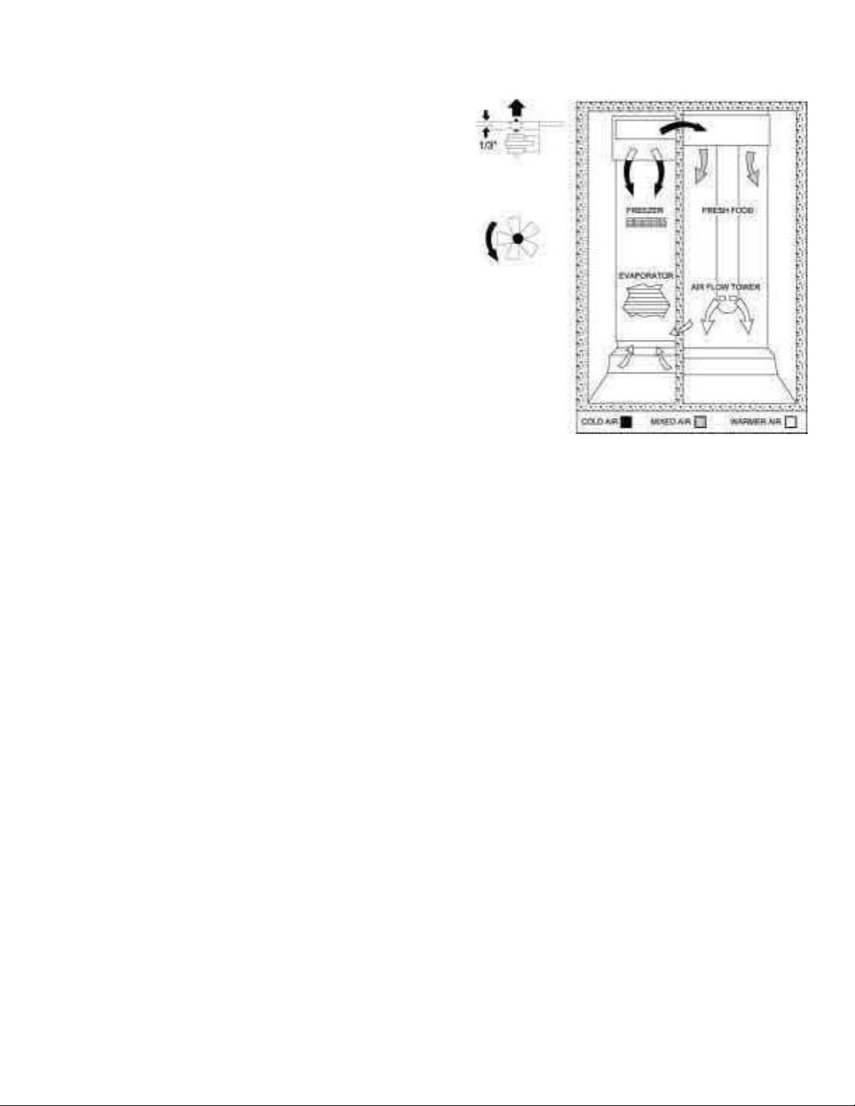
Air Flow (Cabinet Interior)
AIR FLOW
The freezer cabinet is designed so that air is carried inside the lower part
of the air tunnel and through the evaporator when the evaporator fan is
operating. The cold air is then pushed out towards the top of the freezer.
The cooler compartment receives cool air through an electronic shock
absorber that is located in the upper rear of the cooler between the freezer
cabinet and the cooler cabinet. The cushion is controlled by the main
control board and when it is opened, it allows the cold air from the freezer
air tunnel to move inside the cooler's air tower. The cold air tower of the
cooler contains a cooling fan that draws cold air from the freezer (through
the damper) into the air tower. The air tower directs cool air through the
top of the cooler cabinet to two exits. The air tower also directs cool air
down the back of the wall of the cooler cabinet. The cold air draws the air
out of the tower through fans in the tower.
The air returns from the cooler cabinet to the freezer cabinet through an
upright located on the left side of the fresh food drawer.
- 11 -
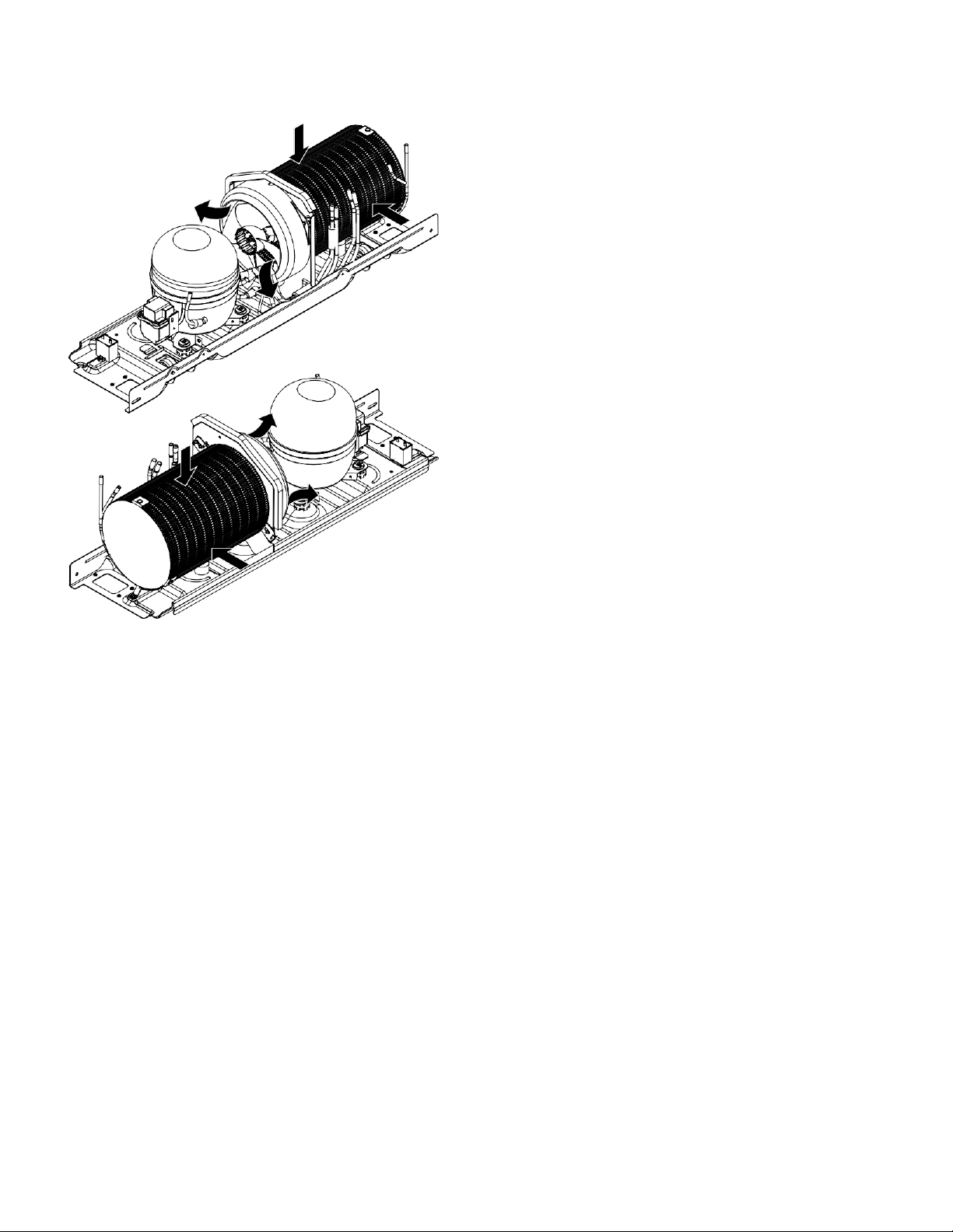
Condenser "Jelly Roll"
The "jelly roll" capacitor is a new type of capacitor. The
condenser fan is located at one end of the "jelly roll" condenser
and a solid plate is located at the other end. Air is drawn
through the outside diameter of the condenser and pulled out
by the condenser fan. The condenser is located in the
compartment of the machine that can be accessed through the
back of the unit in the background
.
GEA00911
- 12 -
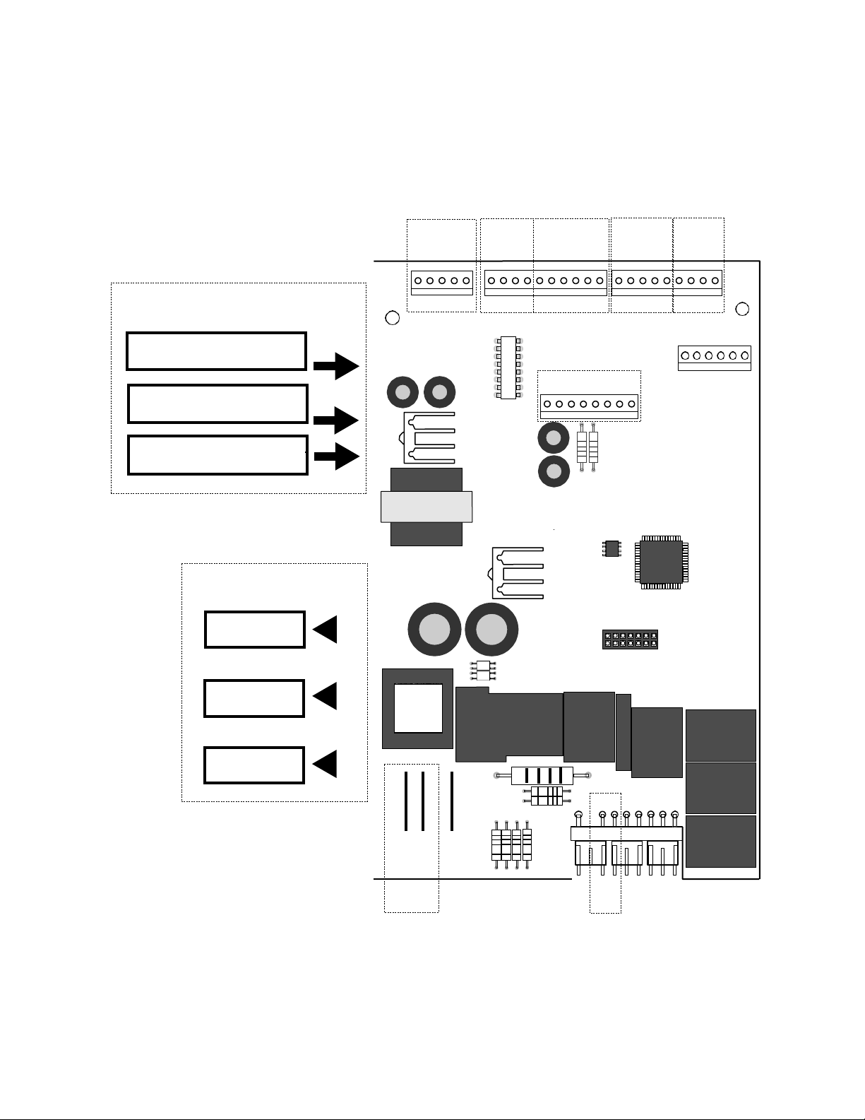
Main Control Board
ENTERS
IGNITION TIME OF THE DESCONG
HEATER. (MINUTES)
COMPRESSOR OPERATING
TIME (MINUTES)
OPEN DOORS ACCUMULATED
ENF AND CONG (MINUTES)
UNIT
PROCESSING
ENTRADAS
SWITCH
PUERTA
COMPRESOR
Y
DESCONGEL.
SALIDAS
SELECC.
MODELO
ENTRADAS
THERMISTO
R
ENTRADAS
CODIFICADOR
SERPENTINES
AMORT.
COMMUNICACION
ENTRADA/SALIDA
SALIDAS VENTILADOR
DEPARTURES
DEFROST.
PRE-COOLI
COOLING
1 COMM
2 +12V
3 -COM
4 DI
5 DO
L1
COMP
DESCONG
1
J4
LINEA
5 1
K4
COMP
J3
1
PAILA_CALT
N
K3
DESCONG. J6
10
DFZ
DFF
OCH
COMUN
AGUA
TRITR
TALADRO
2 1
J2
1
K5
QC
J7
8
K7
PAILA/CALT J1
1
K1
AUGER
K2
C/CR
K6
AGUA J5
9 6
- 13 -
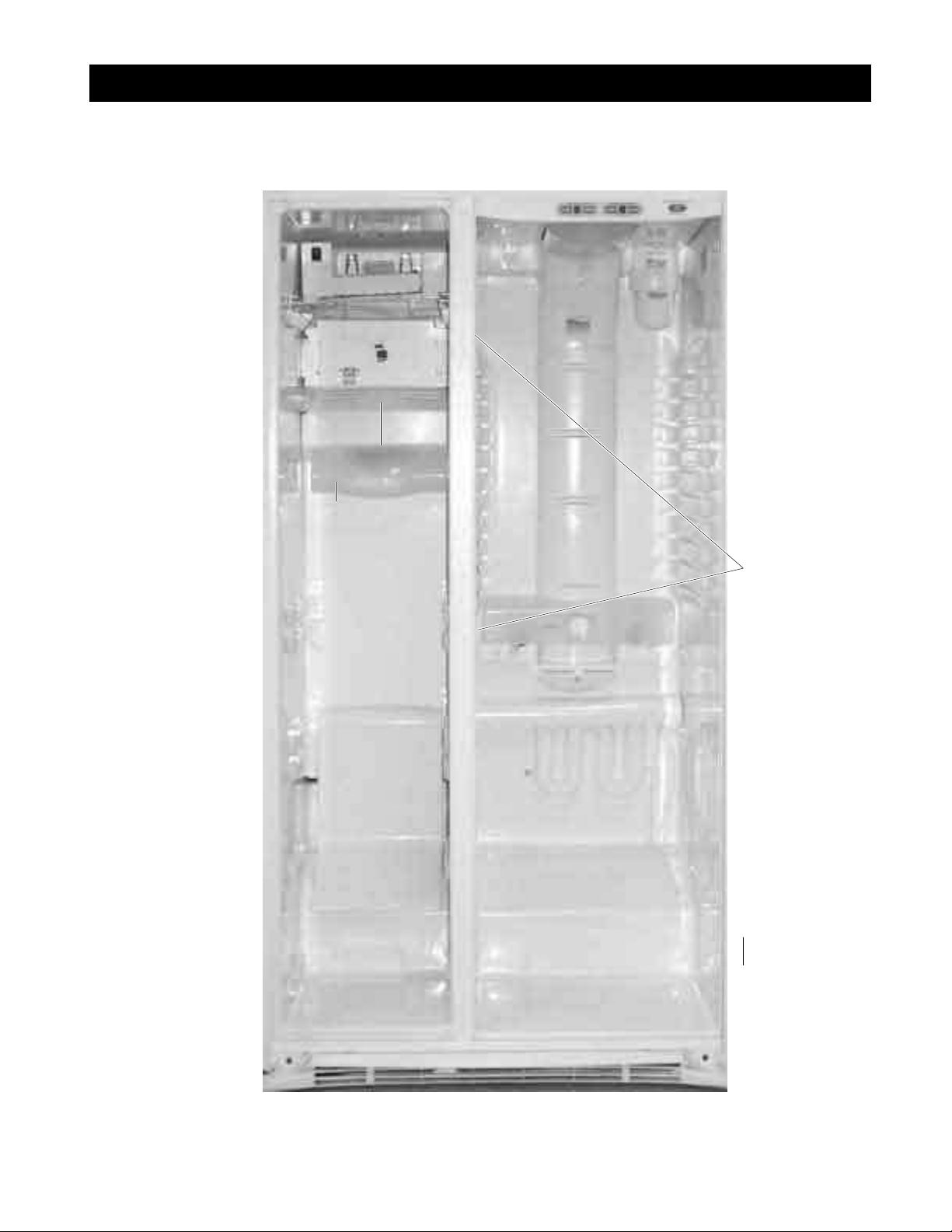
General views of the Locator
Temperature
Controls
Light
Freezer
Switch
Evaporator
Fan
Evaporator
Thermistor
Evaporator
Freez
er
Thermistor
Shock absorber
Coolant Thermistor
Switch Light Cooler

- 14 -
GEA00977
Control
panel
Water
Solenoids
Fan
condenser
Jelly Roll
condenser
Overload and relay
(low cover)
Dryer

- 15 -
Disarmed Mechanic
Content
Door Handle
Door packing
. . . . . . . . . . . . . . . . . . . . . . . . . . . . . . . . . . . . . . . . . . . . . . . .
17
. . . . . . . . . . . . . . . . . . . . . . . . . . . . . . . . . . . . . . . . . . . . . . . .
17
Quick Access to the Door of the Cooler Compartment . . . . . . . . . . . . . . . . . .
17
Switch Light Cooler Door. . . . . . . . . .
. . . . . . . . . . . . . . . . . . . . . . . . . .
18
Door Shelves of the Cooler Compartment . . . . . . . . . .
... . . . . . . . . . . . . . . . . . . . . . 18
Cooler Compartment Shelves ....................................................................................... 18
Cooler Compartment Drawers. . . . . . . . . .
. . . . . . . . . . . . . . . . . . . . . . . . . . . . . .18
Lights of the Cooler Compartment
. . . . . . . . . . . . . . . . . . . . . . . . . . . . . . . . . .
18
Water filter
. . . . . . . . . . . . . . . . . . . . . . . . . . . . . . . . . . . . . . . . . . . . . . . . . . . . . .
19
Fan Cushion and Chiller Study. . . . . . . . . . . . . . . . . .
. . . . . .
19
Shock absorber
DELIFRESH
. . . . . . . .. . . . . . . . . . . . . . . . . . . . . . . . . . . . . . .
20
Chiller Thermistors ......................................................................................................... 20
Temperature Control Panel. . . . .
. . . . . . . . . . . . . . . . . . . . . . . . . . . . . . . . . .
21
Freezer Door Drawers. . . . . . . . . . . .
. . . . . . . . . . . . . . . . . . . . . . .
21
Doors and Door Hinges
. . . . . . . . . . . . . . . . . . . . . . . . . . . . . . . . . . . . . . . . .
21
Adjustment of the Cooler
Door
. . . . . . . . . . . . . . . . . . . . . . . . . . . . . . . . . . . . . . . . . . . . .
22
Rollers
. . . . . . . . . . . . . . . . . . . . . . . . . . .. . . . . . . . . . . . . . . . . . . . . . . . . .
22
Roller Adjustment
. . . . . . . . . . . . . . . . . . . . . . . . . . . . . . . . . . . . . . . . . . . . . . . . . . . .
23
Freezer Compartment Shelves and Drawers .................................................................. 23
Switch Freezer Door Light .............................................................................................. 23
Ice Dispenser
. . . . . . . . . . . . . . . . . . . . . . . . . . . . . . . . . . . . . . . . . . . . . . . . .
23
Drill and Solenoid Drive of Ice Dispenser Cubes
. . . . . . . . .
24
Ice Machine ................................................................................................................... 24

- 16 -
Freezer Light .............................................................................................................. 27
Evaporator Fan
Evaporator thermistor
. . . . . . . . . . . . . . . . . . . . . . . . . . . . . . . . . . . . . . . . . . .
27
. . . . . . . . . . . . . . . . . . . . . . . . . . . . . . . . . . . . . . . . . . .
28
Defrosting Thermostat
De-icer heater
. . . . . . . . . . . . . . . . . . . . . . . . . . . . . . . . . . . . . . .
28
. . . . . . . . . . . . . . . . . . . . . . . . . . . . . . . . . . . . . . .
28
Paila Evaporator Collector ......................................................................................... 29
Evaporator ................................................................................................................. 29
Freezer Thermistor .................................................................................................... 29
Condenser Fan .......................................................................................................... 30
Main Processor Card ................................................................................................. 30
Water solenoids ......................................................................................................... 30
- 17 -
Door Handle
The door handles allow access to the cooler and freezer
compartments. They are mounted in front with 1 Torx head
screw.
1. Using a small flat-bladed screwdriver, slide the trim of the
handle down and pull it out.
2. Remove the lower Torx head screw.
3. Lift the handle with a movement of the inside and up until
the locking ears disengage. Pull the handle out to remove it.
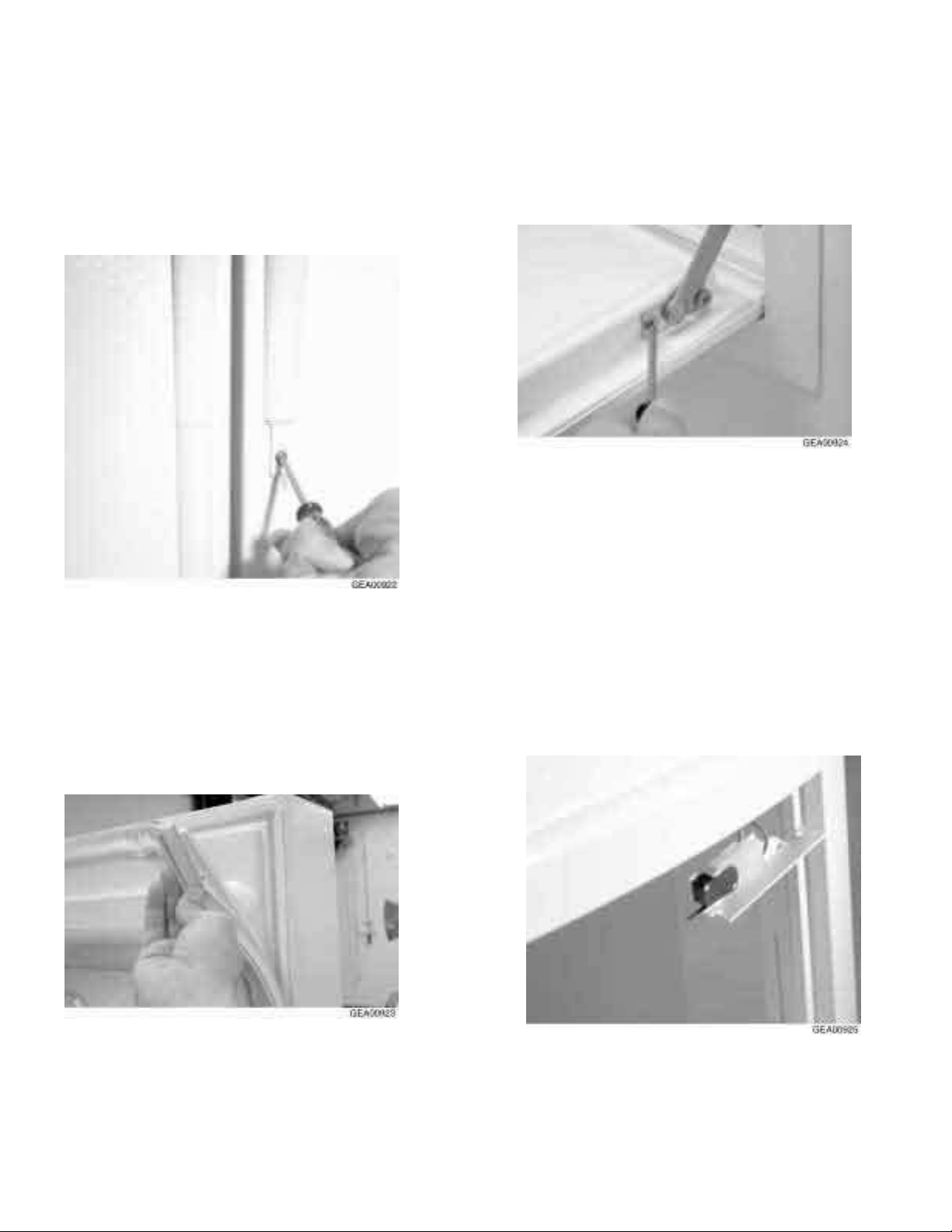
Door packing
The door gasket is a packing set molded
inside a channel located in the door shell.
Door of Easy Access to the Comparison
of the Cooler
The cooler compartment allows access without
opening the cooler door.
1. Open the easily accessible door and remove the Torx head
screws on the hinge (2), located on each side of the door.
2. With a small flat-blade screwdriver, remove the door
frame and door frame assembly.
3. Remove the packing and slide the door out of the frame.
4. The easily accessible door also has an interlock switch
located on the upper right side of the interior frame. Remove
the Phillips screw and slide the switch assembly down and
out.
5. Disconnect the switch wires and remove them.
1.
Open the door.
2. Grasp the gasket and pull it outward until the molded
gasket separates from the door shell
- 18 -
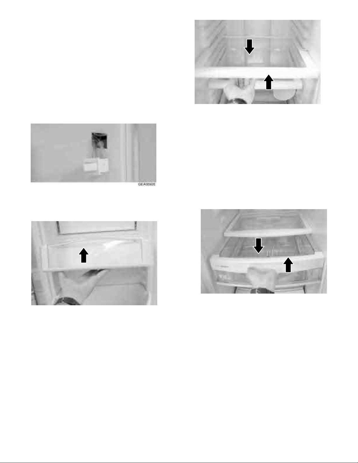
Switch of the Cooler Door Light
In addition to the easy access door light switch, cooler
compartment has a door light switch located on the
corner-right next to the compartment.
1.Use a small flat blade screwdriver to open the
locking lugs and pull the switch out until the
connector wire is visible.
2. Disconnect the connector and remove the
switch.
Door Shelves of the Cooler Compartment
The door shelves allow you to store perishable items
GEA00928
Cooler Compartment Drawers
The cooler compartment drawers are designed
to store fruits, vegetables and DELI items. The
drawers are located in the lower part of the
cooler compartment.
1. Pull the drawer out until the Rhodes are the
mechanical stop.
2. Tilt the drawer upwards and pull out until it is
withdrawn.
1.
Tilt the shelf up and slide it out.
GEA00929
GEA00927
Cooler Compartment Shelves
These shelves allow storage of larger items and
pull them for easy access.
1.
Pull the shelf until the stop tab on the shelf
meets the compartment stop.
2.
Push the stop tab of the shelf down and
pull the shelf out until it is removed.
Lights of the Cooler Compartment
The chiller compartment lights are located on
top and bottom of the chiller compartment.
1.
To access the top lights, remove the opaque
cover by opening the lugs and pulling the cover
down.
 Loading...