


TO CUSTOMERS
Thank you very much for using our two way radio.
This radio of modern design is reasonable structure
with stable functions. It is designed to meet different
customers' need for high quality with easy operation
and perfect capablity. We believe you are pleased with
its nice shape and excellent performance.
This manual is suitable for using the model of AHT-9-UV.

Dual band, dual display, dual standby
A/B band independent operation
2 x 128 channels storage and scanning
Shortcut menu operation mode
FM radio and 25 stations memory
CTCSS/DCS and tone search scanning
Repeater shifts and ARS function
Tone calling 1750Hz tone
25kHz/12.5kHz channel spacing switchable
High/middle/low TX power switchable
Multi working mode switchable
PTT ID and MSK/DTMF encode
Vibration alert function (Optional)
Man down (optional)
8 groups of scrambler (Optional)
Remote stun/kill/activate (Optional)
2T/5T/DTMF encoder and decoder (optional)
Main Functions
Professional FM Transceiver


SET MENU MODE
SHORTCUT MENU OPERATION
DETAILED FUNCTION DESCRIPTION
Scan & Scan Mode setting
Priority Transmit
VOX Level
TX Power setting
Squelch Adjustment
Dual Wait/Standby
LED Display Mode
Backlight Brightness setting
Keypad Beeper setting
Automatic Number Identity
Transmitter Time-Out Timer
Busy Channel Lock-Out
Transmit Over Beeper
Dual Watch/Monitor
Receive Saver
Auto Keypad Lock
Voice Prompt
Power-on Display setting
Repeater Shift setting
Display Channel Name
C-CDC&R-CDC&T-CDC&SCN CD
21
24
29
29
30
30
31
31
31
32
32
32
32
33
33
33
34
34
34
34
35
35
36
36


Professional FM Transceiver
User's Manual
USING TIPS
UNPACKING AND CHECKING EQUIPMENT

03
UNPACKING AND CHECKING EQUIPMENT
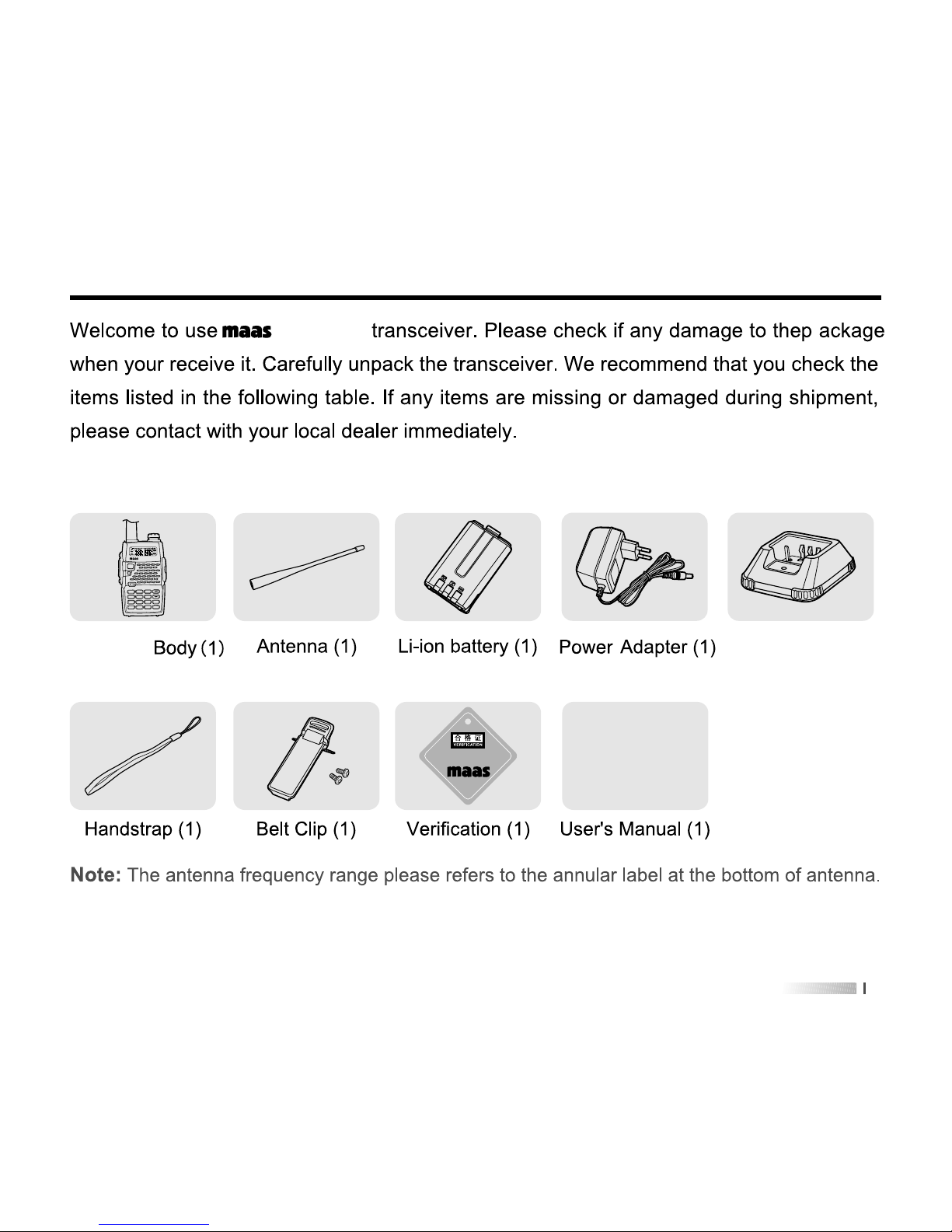
Supplied Items:
AHT-9-UV
AHT-9-UV
FM
EXIT
1
scan
2
Pri3VOX
4
PWr
5
Sql
6
dw
color
8
9
beep
#
t-r
0
ani
*
lock
7
led
A/B
FUN
AHT-9-UV
Charger(1)


0505
AHT-9-UV
1500
7.4V
CHARGING BATTERY PACK
Charging Precaution

07
INSTALLATION OF ACCESSORIES
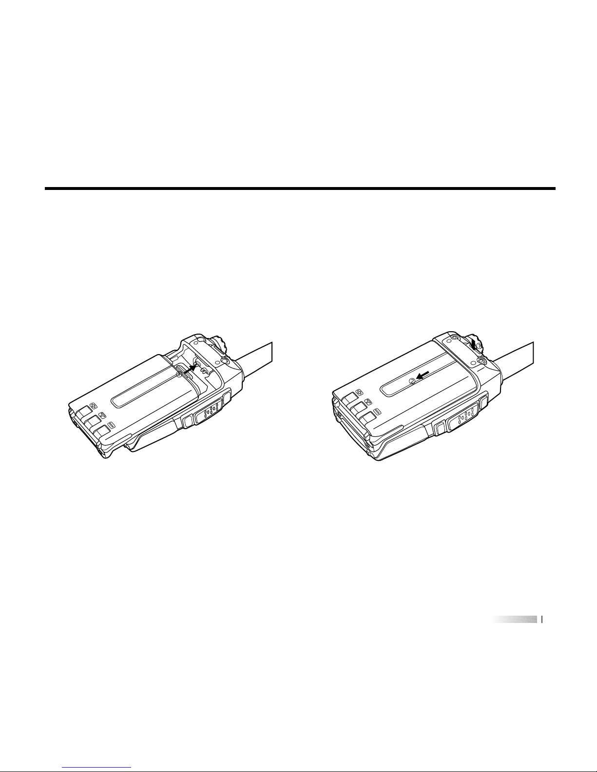
Installation of Battery Pack
1)2)Fit the supplied battery pack into the batter pack trough, then slide it toward the head to
insert it completely---in direction of arrowhead
•.
Push the battery pack lock to release the battery pack and slide it toward the bottom to
remove it out---in direction of arrowhead
•.
Picture 1 Picture 2
CALL
PTT
M
O
NI

09
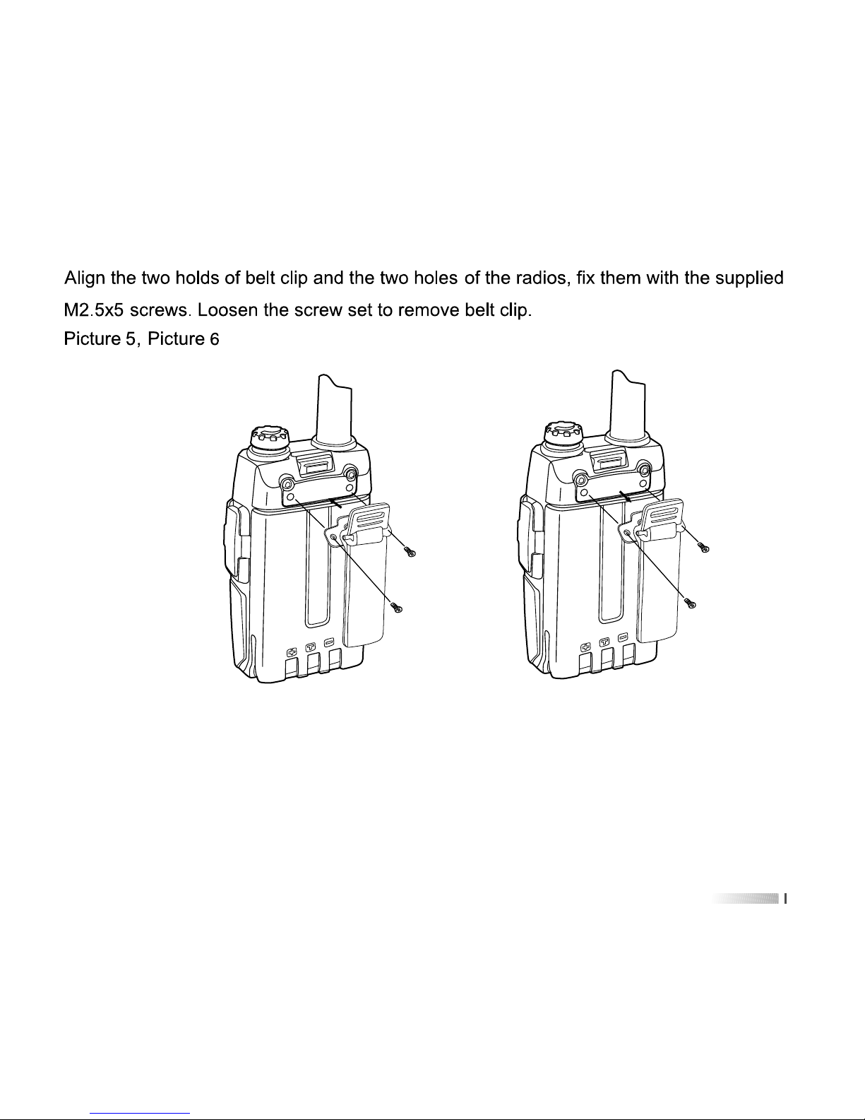
Picture 5 Picture 6
Installing Belt Clip
PUSH
PUSH


Professional FM Transceiver
User's Manual
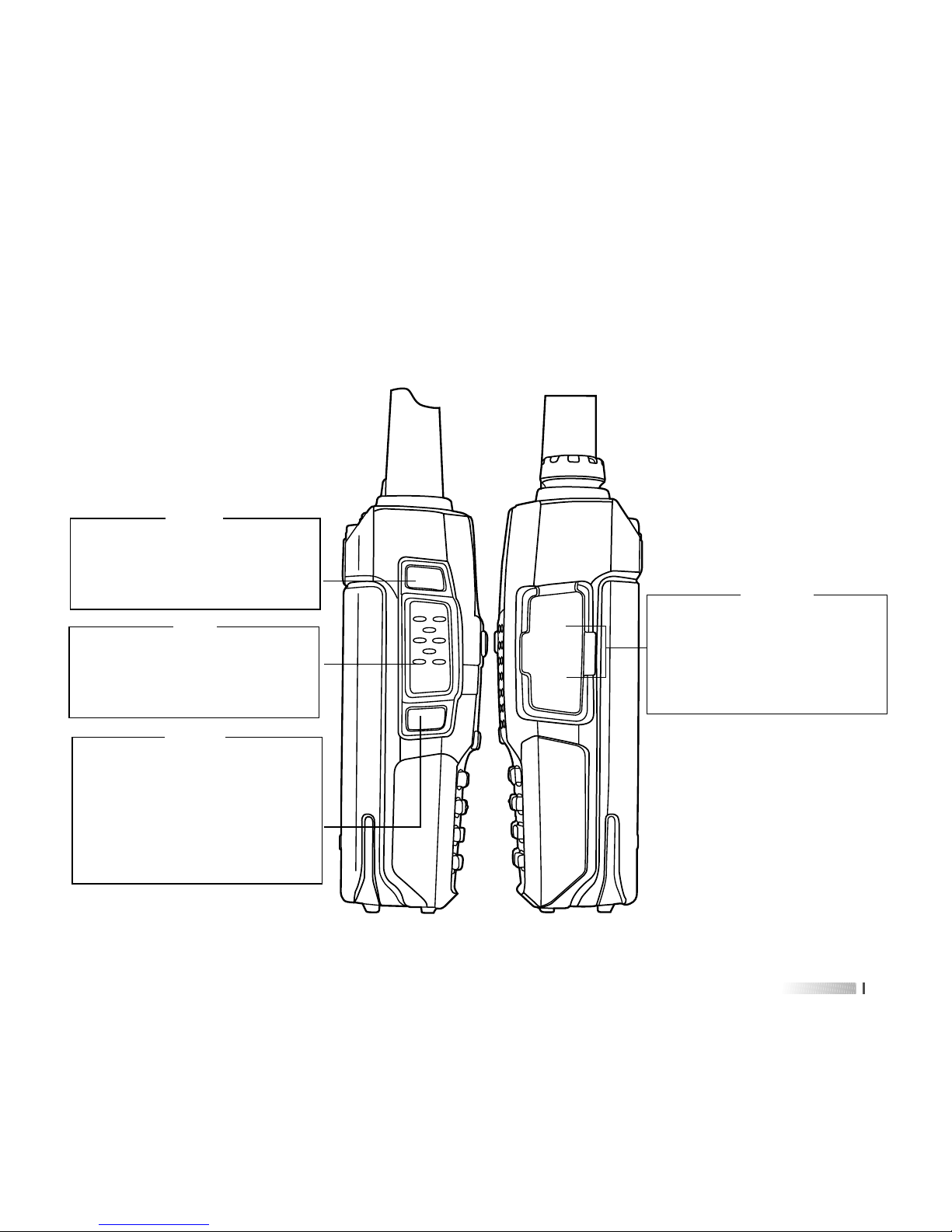
GETTING FAMILIAR

13
CALL
Activates T-CALL (1750Hz) for
repeater access and transmit
DTMF and 2/5 tone signaling.
MONI
Long press this key disables
the noise squelching action,
allowing you to hear very weak
signals near the back-ground
noise level;
MIC/SP
The jack provides connection
points for microphone audio,
earphone audio, speaker and
program cable.
CALL
PTT
MONI
SP
MIC
PTT
Press it to transmit and release
it to receive after your
transmission is completed.

15
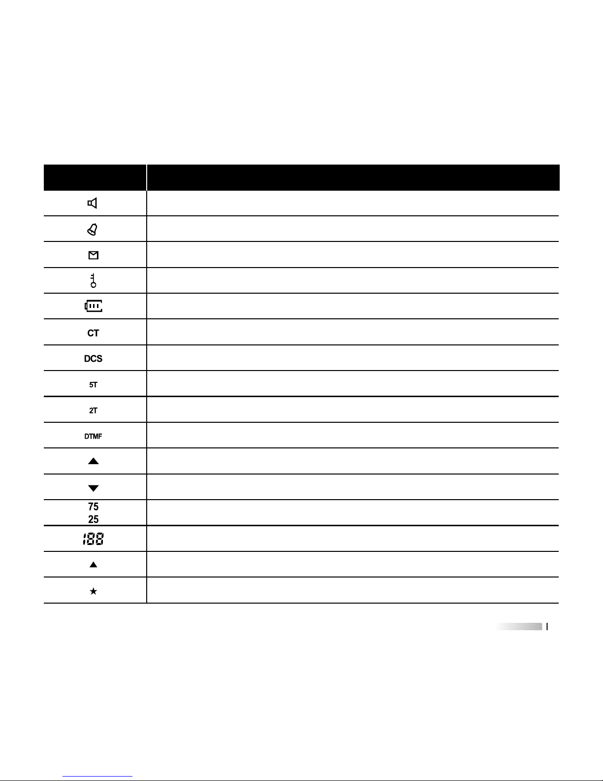
Description of functions
Squelch active
Beep tone active
Receive calling ID or MSG
Scrambler active
Battery power indicator
CTCSS decoder active
DCS decoder active
5 Tone signaling active
2 Tone signaling active
DTMF signaling active
Operating A band indicator
Operating B band indicator
Frequency mantissa indicator
Channel number/Menu items number indicator
Busy channel indicator
Channel scanned available under CH mode
Icons

17
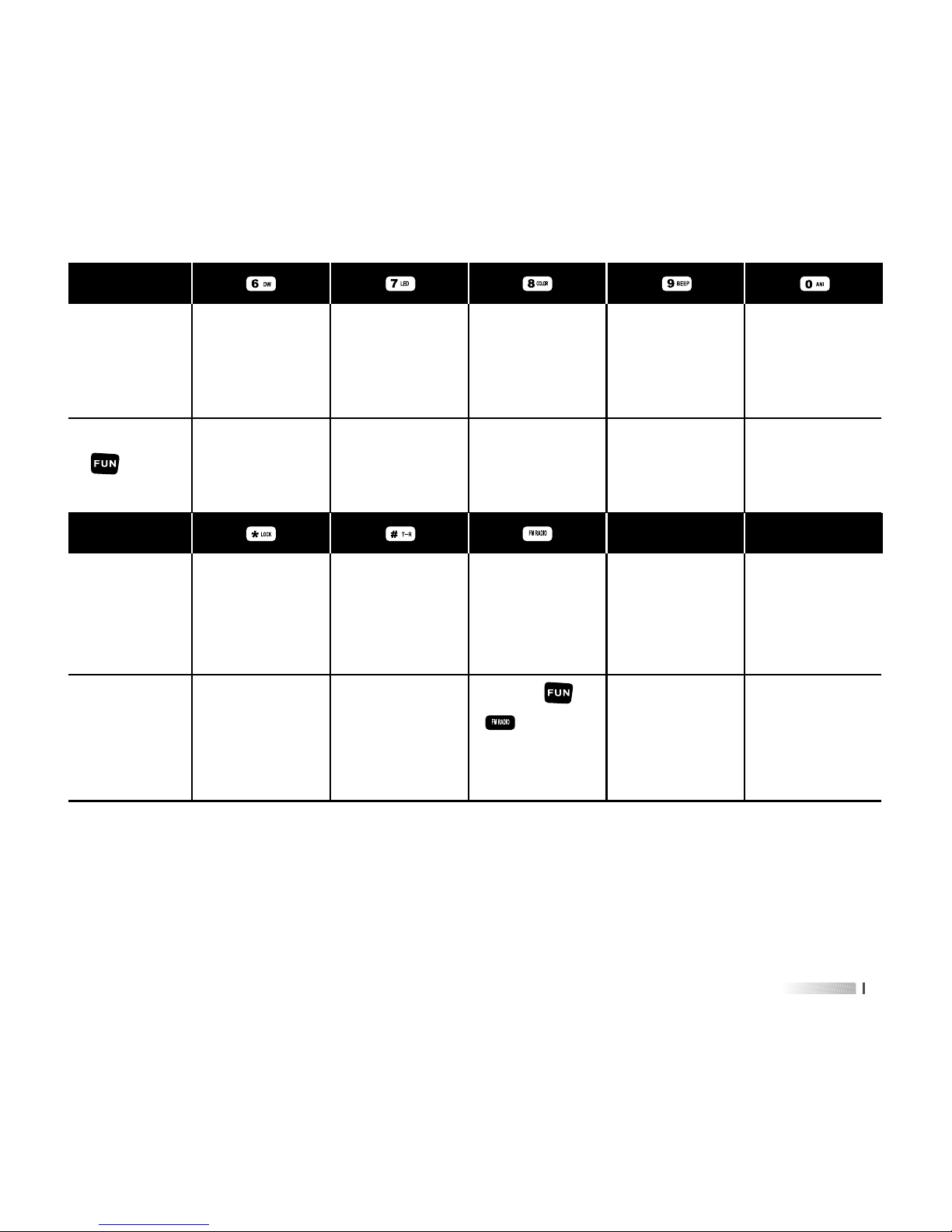
Press
key
[ ] [ ][ ][ ][ ]
Frequency/
Channel No.
entry “6”
Frequency/
Channel No.
entry “7”
Frequency/
Channel No.
entry “8”
Frequency/
Channel No.
entry “9”
Frequency/
Channel No.
entry “0”
Enter dual
wait/standby
item
Enter LED
item
Enter color
item
Enter beep
item
Enter ANI
item
Press
key
[ ]
Left cursor
position
when editing
channel name
Right cursor
position
when editing
channel name
Enter or exit
FM radio
mode
Press and
hold key to
start keypad
lock.
Press and
hold key to
start reverse
frequency
Press [ ] +
[ ] to start
emergency
alert
[ ][ ]
Press
[ ] +


19
WORKING MODE
1) Frequency Mode (VFO)
Under this mode, you can use [ ] / [ ] key to change the frequency or input the
frequency by keypad directly and store channels.
2) Frequency-Channel Mode (MR)
When you have stored a memory channel at least and under VFO mode, press [ ]
key to enter MR mode.
The frequency will be indicated on the display and the channel No. will be indicated at
the right side. If the transceiver display name option is ON and channel name edited, it
will show the name of the channel.
Please see Shortcut Menu Operation Item 23&24. Page 36.
3) Channel Mode (CH)
When you have stored a memory channel at least, press [ ] key and switch power
on the radio, enter CH mode. Channel No. will be indicated on the display and if the
transceiver display mode option is ON, it will show the name of the channel.
Please see Shortcut Menu Operation Item 23&24. Page 36.
4) FM Radio Mode
AHT-9-UV provides frequency 76.00-108.00MHz FM radio.
Under this mode, you can choose FM frequency you need directly. Scan frequency
range and store your favorite channels. Press [ ] to enter and exit FM radio mode.


21
SET MENU MODE
01
SCAN Frequency/Channel Scan
No. LCD Display Description of FunctionAvailable Values
/
SQL level setting
Dual Wait/Standby
LED Display mode
Background Light color
Keypad Beeper Setting
Automatic Number Identity
Transmitter Time-Out Timer
Busy Channel Lock-Out
VOX Switch ON/OFF
Transmit Over Beeper
Dual Watch/Monitor
0-9
ON / OFF
ON / AUTO / OFF
COLOR1 / COLOR2 / COLOR3
ON / OFF
ON / OFF
OFF / 30 / 60 / ... / 270
OFF / WAVE / CALL
ON / OFF
ON / OFF
ON / OFF
SQL
D.WAIT
LED
LIGHT
BEEP
ANI
TOT
BCLO
VOX.SW
ROGER
DW
05
06
07
08
09
10
11
12
13
14
15
04 POWER High/Low TX PowerLOW / HIGH
03 VOX VOX Level Setting1-8
02 TX.SEL Priority TransmitEDIT / BUSY


23
30
31
32
33
34
35
36
Wide/Narrow Band
CTCSS Scanning
DCS Scanning
Man Down
Vibration
Voice scrambler
voice mode
WIDE/NARROW
/
/
ON/OFF
ON/OFF
1-8
OFF/COMP/SCRA
No. LCD Display Description of FunctionAvailable Values
Menu Operation
Under standby mode, press [ ] to enter menu setting, LCD
displays “MENU”.
Press [ ] or [ ] to select the desired menu item, LCD
display current setting of selected item.
Press [ ] to enter and then press [ ] or [ ] to select
the desired setting.
Press [ ] to confirm.
Press [ ] twice to exit and then return to standby mode.
1)
2)
3)
4)
5)
N/W
SEEK 67.0
SEEK D023N
DALARM
VIBRATE
SCR.NO
APRO


25
Item
No.
Item
Name
Enter
item
Screen
Display
Parameter
Explanation
Confirm Return
Standby
Select
parameter
+
Automatic
Number
Identity
10)
+
Transmitter
time-out
timer
11)
+
Busy
channel
lock-out
12)
+
VOX
switch
13)
+
Transmit
over
beeper
14)
+
Dual
watch/
monitor
15)
+
Receive
saver
16)
+
Scan
mode
17)
Press [ ] or
[ ] to change
scan direction
Press [ ] or
[ ] to select
available values
Press [ ] or
[ ] to select
available values
Press [ ] or
[ ] to select
available values
Press [ ] or
[ ] to select
available values
Press [ ] or
[ ] to select
available values
Press [ ] or
[ ] to select
available values
Press [ ] or
[ ] to select
available values
+
Auto
keypad
lock
18)
Press [ ] or
[ ] to select
available values
ON / OFF
OFF / 30... / 270s
OFF / WAVE / CALL
ON / OFF
ON / OFF
ON / OFF
ON / OFF
TO / CO / SE
ON / OFF
Press [ ]
twice to exit
Press [ ]
twice to exit
Press [ ]
twice to exit
Press [ ]
twice to exit
Press [ ]
twice to exit
Press [ ]
twice to exit
Press [ ]
twice to exit
Press [ ]
twice to exit
Press [ ]
twice to exit


27
Item
No.
Item
Name
Enter
item
Screen
Display
Parameter
Explanation
Confirm Return
Standby
Select
parameter
+
RX tone
coder
26)
+
TX tone
coder
27)
+
Shift
direction
28)
+
VFO step29)
+
Wide/
Narrow band
30)
Press [ ] or
[ ] to select
available values
OFF / QT / DCS
Press [ ] or
[ ] to select
available values
OFF / QT / DCS
Press [ ] or
[ ] to select
available values
+ / -
Press [ ] or
[ ] to select
available values
5K / 6.25K / 10K...100K
Press [ ] or
[ ] to select
available values
Wide/Narrow
+
CTCSS
scan
31)
+
DCS
scan
32)
+
DALARM33)
Press [ ] or
[ ] to change
scan direction
Press [ ] key to start
scan
Press [ ] or
[ ] to change
scan direction
Press [ ] key to start
scan
Press [ ] or
[ ] to select
available values
ON/OFF
+
VIBRATE
34)
Press [ ] or
[ ] to select
available values
ON/OFF
+
SCR.NO
35)
Press [ ] or
[ ] to select
available values
1-8
+
APRO
36)
Press [ ] or
[ ] to select
available values
OFF/COMP/SCRA
Press [ ]
twice to exit
Press [ ]
twice to exit
Press [ ]
twice to exit
Press [ ]
twice to exit
Press [ ]
twice to exit
Press [ ]
twice to exit
Press [ ]
twice to exit
Press [ ]
twice to exit
Press [ ]
twice to exit
Press [ ]
twice to exit
Press [ ]
twice to exit


Functions: under VFO/MR/CH mode, AHT-9-UV allows you to scan the entire current
operating band and memory channels.
Enter Menu 1
st
and press [ ] key to start scanning.
When you have started scanning, press [ ] / [ ] key to change direction. And it
will halt on a signal it encounters, press PTT key to stop scanning; Press MONI key to
stop scanning temporarily; Press [ ] key again to exit the scanning function.
Scanning operation is basically the same in each of the above modes. Before you begin,
take a moment to select the way in which you would like the scanner to halt on a signal.
Enter Menu 17
th
to set scan mode. Default: TO.
Three options for the scan mode are available under VFO mode:
TO: In this mode, the scanner will halt on a signal it encounters, and will hold there for
some time. If you do not take action to disable the scanner within the time period,
the scanner will resume even if the stations are still active.
CO: In this mode, the scanner will halt on a signal it encounters, and will hold there if
the stations are still active. And after the carrier has dropped, the scanner will
resume.
SE: In this mode, the scanner will halt on a signal it encounter, it will not restart
automatically; you must manually re-initiate scanning if you wish to resume.
29
DETAILED FUNCTION DESCRIPTIONS
1) Scan & Scan Mode setting (SCAN&SCANS---MENU 1&17)


31
4) TX Power setting (POW---MENU 4)
Functions: you can select high/low TX power according to your talking environment
and need. When you store memories, you can store High and Low power
settings separately in each memory.
Enter Menu 4
th
to set TX power.
High: 4W
Low: 0.5W, when you select Low power, the “L’ icon will appear on the display.
5) Squelch Adjustment (SQL---MENU 5)
Functions: AHT-9-UV’s Squelch system allows you to mute the background noise when
no signal is being received. Not only does the Squelch system “standby”
operation more pleasant, it also significantly reduces battery current
consumption.
Enter Menu 5
th
to set SQL level. Default: 5.
6) Dual Wait/Standby (D.WAIT---MENU 6)
Functions: AHT-9-UV allows you to receive the sub band signal even if you are working
on the operating band. It could monitor the signal under both master and
sub band at the same time.
Enter Menu 6
th
to set Dual Wait. Default: ON.


33
11) Transmitter Time-Out Timer (TOT---MENU 11)
Functions: the TOT feature provides a safety switch which limits transmission to a
pre-programmed value. This will promote battery conservation by not
allowing you to make excessively-long transmissions, and in the event of
a stuck PTT switch it can prevent interference to other users as well as
battery depletion.
Enter Menu 11
th
to set TOT. Default: OFF.
12) Busy Channel Lock-Out (BCLO---MENU 12)
Functions: the BCLO feature prevents the radio’s transmitter from being activated if a
signal strong enough to break through the “noise” squelch is present. On a
frequency where stations using different CTCSS or DCS codes may be
active, BCLO prevents you from disrupting their communications
accidentally (because your radio may be muted by its own tone decoder).
Enter Menu 12
th
to set BCLO. Default: OFF.
OFF: Disable BCLO feature.
WAVE: the radio’s PTT will be prevented only if the frequency is busy used.
CALL: the radio’s PTT will be prevented only the frequency and tone coder is the same.
13) Transmit Over Beeper (ROGER---MENU 14)
Functions: sending a beeper to inform the receiver TX is over.
Enter Menu 14
th
to set ROGER. Default: OFF.


35
18) Power-on Display setting (OPN.SET&VLT&PON.MSG---MENU 20&21&22)
Functions: choose power-on display mode and edit power-on message
Enter Menu 20
th
to set OPN.SET. Default: OFF.
OFF: display model version
DC: battery power voltage
MSG: power-on message
Enter Menu 21
st
to check battery voltage.
Enter Menu 22
nd
to edit power-on message, also you can edit it directly by
program software.
Using [ ] / [ ] to select character; [ ] / [ ] to switch cursor position.
19) Repeater Shift setting (OFFSET&S-D---MENU 23&28)
Functions: repeater stations, usually located on mountaintops or other high locations,
provide a dramatic extension of the communication range for low-powered
hand-held or mobile transceivers.
Under VFO mode, you can set the magnitude and direction of the repeater shift.
Enter Menu 23
rd
to set magnitude of the repeater shift.
Available values: 0.00 ~ 99.95 MHz
Enter Menu 28
th
to set the repeater shift direction. Default: OFF.


37
CTCSS TONE FREQUENCY (Hz)
67.0
8.25
100.0
123.0
151.4
171.3
189.9
210.7
250.3
69.3
85.4
103.5
127.3
156.7
173.8
192.8
218.1
254.1
71.9
88.5
107.2
131.8
159.8
177.3
196.6
225.7
-
74.4
91.5
110.9
136.5
162.2
179.9
199.5
229.1
-
79.7
97.4
118.8
146.2
167.9
186.2
206.5
241.8
-
77.0
94.8
114.8
141.3
165.5
183.5
203.5
233.6
-


39
Function 2: TONE Search Scanning
In operating situations where you don’t know the CTCSS/DCS tone being used by
another station or stations, you can command the radio to listen to the incoming signal
and scan in search of the tone being used.
Enter Menu 31
st
/32nd to start CTCSS/DCS searching.
If the Tone scan feature does not detect a tone or code, it will continue to scan
indefinitely. When this happens, it may be that the other station is not sending any tone.
You can press PTT key to halt the scan at any time.
You also can press MONI key during Tone scanning to listen to the (muted) signal from
the other station. When you release the MONI key, Tone scanning will resume.
Tone Scanning works either in the VFO or MR modes.
Function 3: TONE Calling (1750Hz)
If the repeaters in your country require a 1750Hz burst tone for access (typically in
Europe), you can press and hold CALL key for 2s and transmitter will automatically be
activated, and a 1750Hz audio tone will be superimposed on the carrier. Once access
to the repeater has been gained, you may release CALL and use PTT key for activating
the transmitter.
22) VFO Step setting (STEP---MENU 29)
Functions: setting of the synthesizer steps
Enter Menu 29
th
to set VFO step.
Available Values: 5/6.25/10/12.5/25/50/100 kHz


41
ADVANCED FUNCTIONS
If select MSK, you can choose from 0-9, 4 digits in maximum for BOT; for EOT, you can
choose from 0-9 and A-Z, 6 characters in maximum. While select DTMF, for BOT, you
can choose from 0 to 9 and A to D, 7 characters in maximum. For EOT, you can choose
from 0-9 and A-Z and 7 characters in maximum. You can select “BOT, EOT, or BOTH,
then save to the radio.
PTT ID (Programmed by AHT-9-UV software)
This transceiver supports two optional signalings, MSK and DTMF. DTMF signaling only
supports encoding.
Set transmitting and receiving frequency in advance and then program PTT ID via
software, click in sequence: -Program-Optional Features-PTT ID setting. And click the
ANI (mark •). You can input character in BOT and EOT.
1) PTT ID SETTING


43
TONE CALLING (1750Hz TONE)
To access a repeater, press and hold in [ ] key for the amount
of time specified by the repeater. The transmitter will automatically
be activated, and a 1750Hz audio tone will be superimposed on the
carrier. Once access to the repeater has been gained, you may
release [ ] key and use PTT for activating the transmission.
5)
CHANNEL STORAGE AND DELETE6)
Channel Storage
Under VFO mode, input desired frequency by keypad directly or
select one by pressing [ ] or [ ], and then press [ ] +
[ ], the digits blinks at the right top of LCD, press number to
input desired channel directly or press [ ] or [ ] to choose
desired one, then press [ ] for storage.
Note: after you input desired channel number, if it blinks, it means
that this channel is already occupied, you can choose another
one.
e.g.: to store the frequency: 450.325MHz with CTCSS: 151.4 to the
channel 05, the step are as follows:
1) Under VFO mode, input 4-5-0-3-2-5


45
FM RADIO FUNCTION
1) On/off radio receiver
Under standby mode, press [ ] to open FM radio function, LCD
display “76.00M”, then press [ ] again, radios receiver is off.
Note: under FM radio mode, if receiving the signal, the radio will be out
of FM mode, after 5S, it will be back to FM mode when the signals
disappear.
2) Mode selection:
Under FM radio mode, press [ ] to switch between FM memory
mode and FM frequency mode (this function is unavailable when
there is not FM memory channel)
3) Frequency selecting
Under FM frequency modae, input the digits directly by keypad or
press [ ] or [ ] to choose the desired frequency. Under FM
memory mode, press [ ] or [ ] to choose the desired channel.
4) FM radio search:
Under FM radio mode, press [ ] + [ ], then press [ ]
again to enter FM radio scanning, you will see “
RADIO SEEK.UP”
in the screen, press [ ] or [ ] to change scanning direction.
Radio will stop scanning when frequency is available and then exits.
If you rotate the encoder knob, it will scan again; press any key
7)


47
clone state. The “Clone” will be heard, LCD displays “CLONE”
Press [MONI] key of the master radio to start wired clone. During
cloning, the master radio displays "Sending" and deputy one
displays "End". If cloning succeeds, the master radio returns to
the clone preparation state, and it lights orange. it displays "Error".
Please check the cloning cable and then press [MONI] to enter
cloning state again.
3)


49
OPTIONAL SIGNALINGS
Optional Signalings (Programmed by AHT-9-UV software)
This transceiver supports four optional signalings (MSK, DTMF, 2-Tone, 5-Tone).
Click in sequence “program•Optional Features•Optional Signal•Common Set”, the
programming software also has three versions: simple version (Supporting MSK Signaling),
DTMF version (Supporting MSK signaling and DTMF signaling) and 5T&2T version
(Supporting MSK signaling and 2T/5T signaling). Please check the version first before
programming. If the version of programming software is different from the radio version,
you cannot program via software.
In transmitting, maybe radio cannot receive the complete signaling, because radio needs
time to switch when in power-saving state. We have to set the “Digit delay”, that’s, to send
a carrier first, let radio receive signal, then send Signaling to make sure it will be received.
The suggested time for delay time is more than 400S
Press [ ] key, LCD will display “DTMF?”, “MSK?” or “2Tone?”, Press [ ] and [ ]
keys to make call with the desired call list message. If the corresponding call list has not
been edited, the function is not available.


51
Step 6: Set the optional signal of the desired channel to be DTMF. Input the ID code and
then save it after finishing it.
Make DTMF call with the transceiver
First method
1)
2)
Power on, then select the channel with DTMF signal
Press [ ] key, LCD displays “CALL/DTMF?”,
then press [ ] – [ ] keys to make call with the
desired call list message. If the corresponding call list
has not been edited, it will sound “DU”.
Second method
Press PTT and hold on and then press the number key to transmit.
MSK Part
Edit the MSK message of the transceiver (ID code is for receiving while calling list message
is for transmitting.)
Click in sequence “program•Optional Features•Optional Signal•MSK”
Step 1: Edit the Fast Call list via programming software, radio can store up to 10 groups
(0-9) last calling list in total
Step 2: Input the desired code into the corresponding list, 4 characters in maximum, Click
[save] after finishing it then exit.
Click “More” after frequency you edit, programming in the popup

53
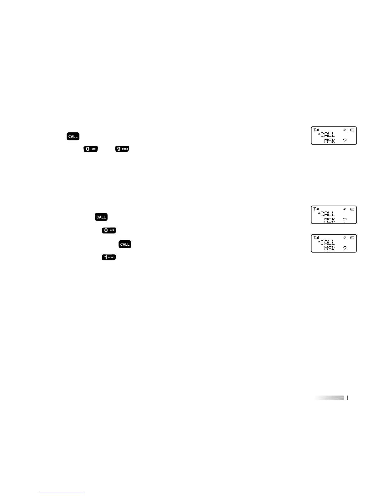
Make MSK call with the transceiver
1)2)Power on, then select the channel with MSK signal
Press [ ] key, LCD displays “CALL/DTMF?”,
then press [ ] – [ ] keys to make call with the desired
call list message. If the corresponding call list has not been
edited, it will sound “DU”.
e.g.: program the above frequency and MSK signal into two radio.
input ID code 1234 into radio A, and input 2345 into radio
B. Press [ ], LCD displays “CALL/MSK?”,
then press [ ], you can call B with A. if you want to call
A with B, press [ ], LCD displays “CALL/MSK?”,
then press [ ], that is to say, if you want to call one radio,
just input the ID code of that radio.
2-Tone Part
Edit 2Tone message:
Step 1: Edit the Fast Call list via programming software, radio can store up to 10 groups
(0-9) last calling list in total
Step 2: Input the encoding-requested A-Tone (the first tone), B-Tone (the second tone)
and the gap time between A-tone and B-tone, the default setting is 100S
In encoding, A tone will sound 1S while B Tone will sound 3S. But when there is
only A tone in the call list as group call tone, A tone will sound 5S. Please refer to


55
Make 2-tone call with the transceiver
1)2)Power on, then select the channel with 2-Tone signal
Press [ ] key, LCD displays “CALL/2T?”,
then press [ ] key to transmit 2-Tone while press [ ] to
transmit a single tone/Group call. If the corresponding call list
has not been edited, it will sound “DU”.
5-Tone Part
Edit 5tone message
Click in sequence “program•Optional Features•Optional Signal•5-Tone” to program
5-Tone ID and 5-Tone international standard group.
The group numbers 0-9 in the call list is used to edit the 5tone ID of the radio you want to
call. You can put 0-9, A, B, C, D and number (including repeated ID)
The group in the international standard are: CCIR1, CCIR2, CCITT, EEA, EIA, NATEL,
ZVEL1, ZVEL2, 9 groups in total.
Select one of them and input self ID (input in ID), and then write into the radio.


57
This transceiver has 8 groups’ 5-Tone encoder and decoder to support the different
channels, the operation of calling/transmitting 5-Tone are as follows:
1)
2)
3)
4)
Select the channel with 5-tone signal.
(LCD displays “5T” at the right bottom of radio)
Press [ ], LCD displays “------”
Input the 5-Tone ID of radio you want to call
e.g.: input A-2-3-5-B in Group 2 in sequence, at this time the
keys [ ], [ ], [ ], [ ] stand for “A”, “B”, “C”,
and “D”, so if you want to input A-2-3-5-B, press [ ],
[ ], [ ], [ ] [ ], in sequence
Press PTT to transmit


remote un-stun, the radio will quit the remote stun status and enter
normal operation.
1)2)Simple version don’t have this function
DTMF version
A. Click in sequence “program•Optional Features•Optional Signal•DTMF•Remote
kill/stun code” to input your desired Remote kill/stun code
B. In transmitting, input the Remote kill/stun code for the radio which you want to remote
kill/stun.
C. Remote revive code is “remote stun code + #”, but the remote kill one aren’t able to
be revived by this way.
e.g.: There are two radios with the same DTMF encode. The remote stun code for radio
A is 12345678, remote kill one is 87654321. If you want to remote un-stun it,
please use another radio to input the working frequency of radio A, press [PTT] to
transmit, at the same time to input remote stun code 12345678. After receiving this
59


revive it, press [ ] and input remote un-stun code 2345678, the radio will quit the
remote stun status and enter normal operation. The operation of remote kill is the
same to remote stun.
61


Frequency Range
Frequency stability
Channel No.
Antenna
Antenna Impedance
Mode of operation
Dimensions (WxHxD)
144-146MHz 430-440MHz
±2.5PPm
128x2
High gain antenna
50Ω
Simple or semi-duplex
128 x 63 x 33mm
General
TECHNICAL PARAMETERS
63
AHT-9-UV


Please cut along with this line
Guarantee
Model Number:
Serial Number:
Purchasing Date:
Dealer:
User's Name:
Address:
Telephone:
Telephone:
Post Code:
Remarks:
1
2
3
4
5
This guarantee card to be kept by the user, no replenishment if lost.
This guarantee card to be filled & chopped by the dealer, or it is invalid.
Don't alter the guarantee card, please coufirm the serial number on the guarantee card is same as
that on the machine.
One-year guarantee, charger, battery, ear-phone, antenna and cable are not under guarantee.
The user can get repairing service from the followingways:
Go to the shop where you buy the machine.
Our local repairing agents.
Send back to our company.

 Loading...