


Thank you very much for using our two way radio.
This radio of modern design is reasonable structure
with stable functions. It is designed to meet different
customers' need for high quality with easy operation
and perfect capablity. We believe you are pleased with
its nice shape and excellent performance.
This manual is suitable for using the model of
AHT-28-V/AHT-78-U.
Maas
AHT-28-V/AHT-78-U
Handheld Transceivers
User’s Manual

www.maas-elektronik.com
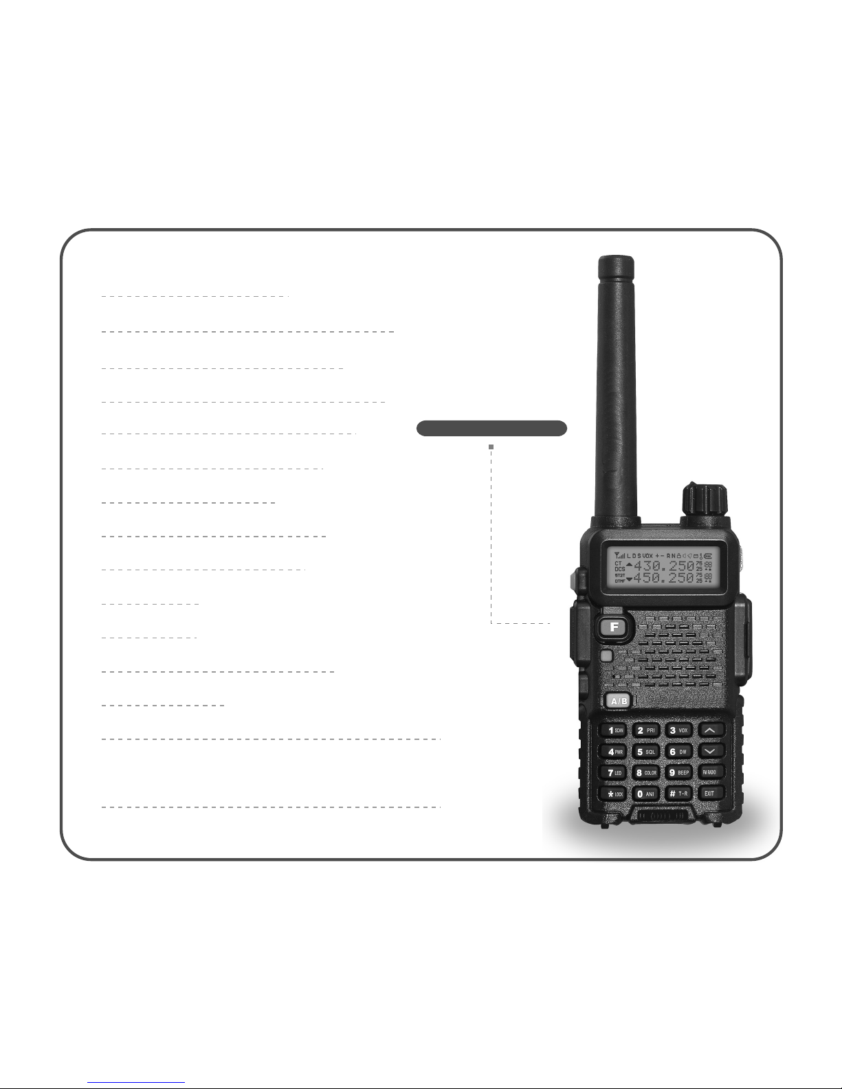
Single band, dual display, dual standby
A/B band independent operation
2x128 channels storage and scanning
FM radio and 25 stations memory
Wide/Narrow band selectable
VOX 0~9 grade setting
Chinese/English voice prompt
CTCSS/DCS and scanning
1750Hz tone
ANI function
Shortcut menu operation mode
Emergency alert
DTMF and remote stun/kill/activate (optional)
8 groups of scrambler, 2/5 tone, remote stun/
kill/activate (optional)
Main Functions


Reset Mode
SET MENU MODE
SHORTCUT MENU OPERATION
DETAILED FUNCTION DESCRIPTION
Scan & Scan Mode setting
Priority Transmit
VOX Level & VOX Switch
TX Power setting
Squelch Adjustment
Dual Wait/Standby
LED Display Mode
Background Light Color
Keypad Beeper setting
Automatic Number Identity
Transmitter Time-Out Timer
Busy Channel Lock-Out
Transmit Over Beeper
Dual Watch/Monitor
Receive Saver
Auto Keypad Lock
Voice Prompt
Power-on Display setting
Repeater Shift setting
Display Channel Name
21
22
25
30
30
31
31
32
32
32
33
33
33
33
34
34
34
35
35
35
35
36
36
37


User's Manual
USING TIPS
UNPACKING AND CHECKING EQUIPMENT
www.maas-elektronik.com

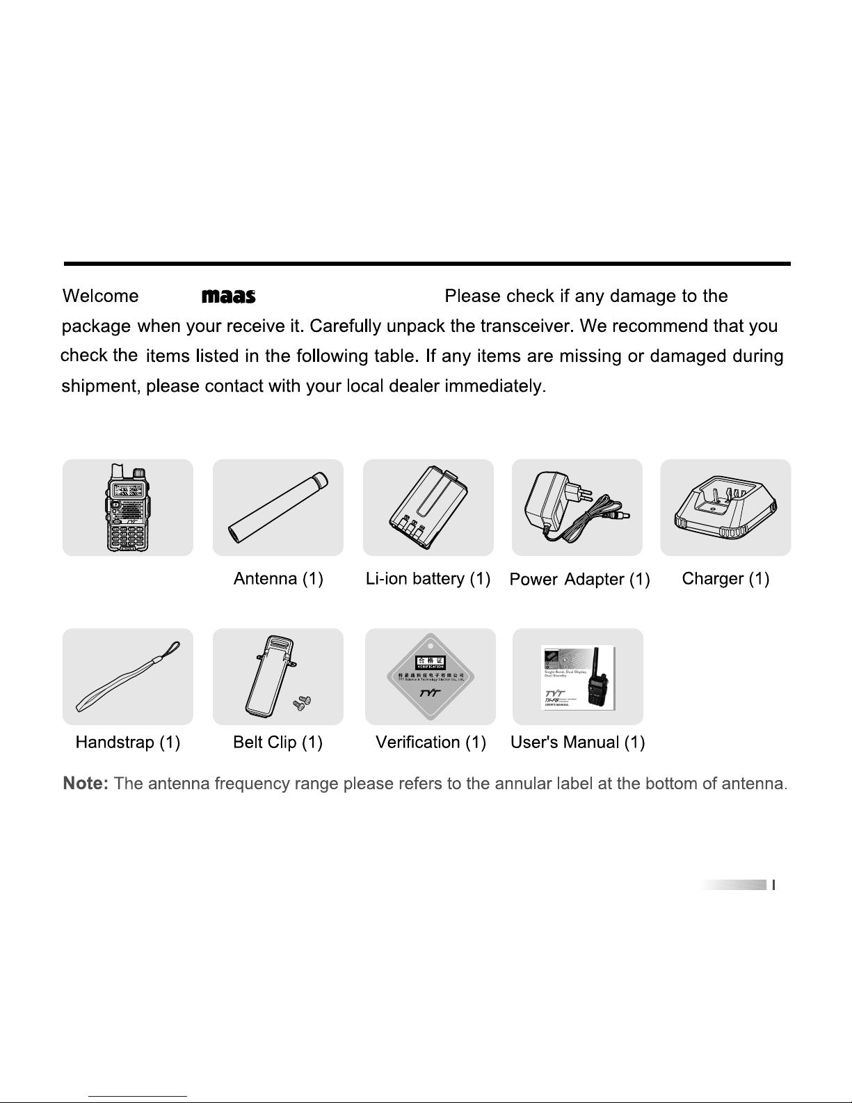
Transceiver (1)
Supplied Items:
to use AHT-28-V/AHT-78-U.

05
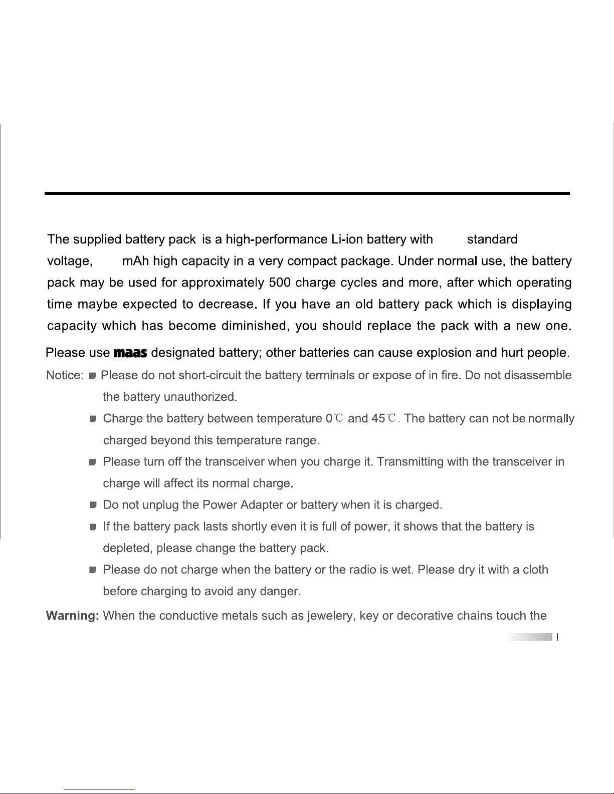
CHARGING BATTERY PACK
1600
7.4V
Charging Precaution

INSTALLATION OF ACCESSORIES
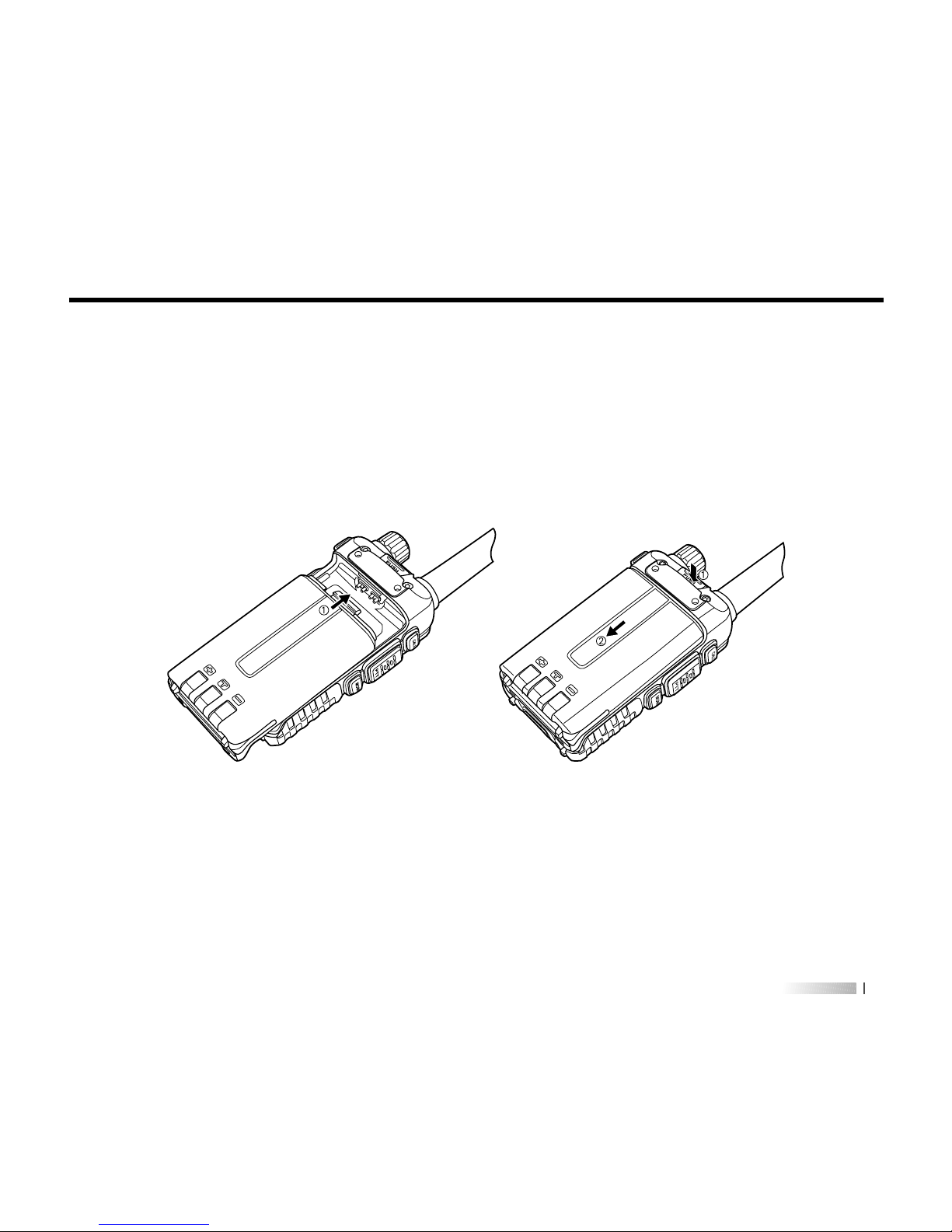
Installation of Battery Pack
1)2)Fit the supplied battery pack into the batter pack trough, then slide it toward the head to
insert it completely---in direction of arrowhead (Picture 1).
Push the battery pack lock to release the battery pack and slide it toward the bottom to
remove it out---in direction of arrowhead (Picture 2).
Picture 1 Picture 2

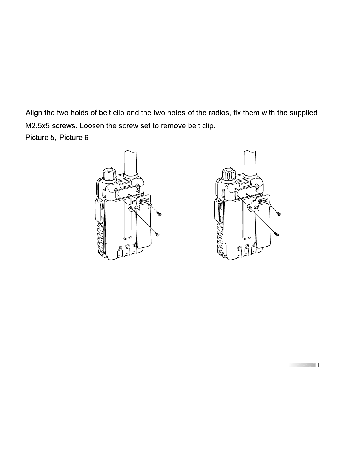
Picture 5 Picture 6
S
P
M
I
C
P
U
S
H
S
P
M
I
C
P
U
S
H
Installing Belt Clip


User's Manual
GETTING FAMILIAR
www.maas-elektronik.com


MONI
PTT
CALL
SP
MIC
CALL
Activates T-CALL (1750Hz) for
repeater access and transmit
DTMF and 2/5 tone signaling.
PTT
Press it to transmit and release
it to receive after your
transmission is completed.
MONI
Press this key disables the
noise squelching action,
allowing you to hear very weak
signals near the back-ground
noise level.
MIC/SP
The jack provides connection
points for microphone audio,
earphone audio, speaker and
program cable.


Description of functions
Squelch active
Beep tone active
Receive calling ID or MSG
Scrambler active
Battery power indicator
CTCSS decoder active
DCS decoder active
5 Tone signaling active
2 Tone signaling active
DTMF signaling active
Operating A band indicator
Operating B band indicator
Frequency mantissa indicator
Channel number/Menu items number indicator
Busy channel indicator
Channel scanned available under CH mode
Icons


Press
key
[ ] [ ][ ][ ][ ]
Frequency/
Channel No.
entry “6”
Frequency/
Channel No.
entry “7”
Frequency/
Channel No.
entry “8”
Frequency/
Channel No.
entry “9”
Frequency/
Channel No.
entry “0”
Enter dual
wait/standby
item
Enter LED
item
Enter color
item
Enter beep
item
Enter ANI
item
Press
key
[ ]
Left cursor
position
when editing
channel name
Right cursor
position
when editing
channel name
Enter or exit
FM radio
mode
Press and
hold key to
start keypad
lock.
Press and
hold key to
start reverse
frequency
Press [ ] +
[ ] to start
emergency
alert
[ ][ ]
17
Press
[ ] +


19
MODEL VERSION
The AHT-28-V/AHT-78-U has 3 versions in total:
1) Simple version 2) DTMF version 3) 5T&2T version
Set Menu 20
th
Power-on Display OFF, you will find your AHT-28-V/AHT-78-U model
version information when you switch the transceiver power on.
DTMF and 2/5 TONE version will be with remote kill/stun/activate/revive function.
Only 2/5 TONE version will be with 8 groups of scrambler function.
Please choose the right AHT-28-V/AHT-78-U model type when you use software to program
it. If not, it will affect some functions operation. Detail please see picture as below:


5) MENU Mode
Press [ ] key to enter MENU mode, there are 34 items in total. Please see SET
MENU MODE. Page 22
6) Reset Mode
Press [ ] key and switch the power on to enter Reset mode, then press [ ] key
to enter.
1. [ ] or [ ] key to select VFO/FULL.
2. VFO: initialize all setting under frequency mode.
3. FULL: initialize all setting under frequency and memory mode.


2322
16
17
18
19
20
21
22
RX.SAV
SCAN.S
AUTOLK
VOICE
OPNSET
DC
MSGSET
Receive Saver
Scan Mode
Auto Keypad Lock
Voice Prompt
Power-on Display
Battery Power Voltage
Power-on Message
ON / OFF
TO / CO / SE
ON / OFF
ON / OFF
OFF / DC / MSG
/
-1A, @
No. LCD Display Description of FunctionAvailable Values
23B
24
25
26
27
28
29
DIS.NM
CHNAME
C-CDC
R-CDC
T-CDC
S-D
STEP
Display Channel Name
Channel Name Editing
TX/RX Tone coder
RX Tone coder
TX Tone coder
Shift Direction
VFO Step
ON/OFF
-1A, @
OFF / 67.0 / D023N
OFF / 67.0 / D023N
OFF / 67.0 / D023N
+ / - / OFF
5K / 6.25K / ... / 25K
23A OFFSET
Repeater Shift
(Under VFO mode)
0.000-99.995MHz
Receive Saver
Scan Mode
Auto Keypad Lock
Voice Prompt
Power-on Display
Battery Power Voltage
Power-on Message


2524
SHORTCUT MENU OPERATION
TX power
setting
4)
+
Frequency
/Channel
scan
SQL level
setting
5)
+
Dual wait/
standby
6)
+
+
Priority
Transmit
2)
+
VOX level
setting
3)
+
Keypad
beeper
9)
Background
light color
8)
+
LED
display
mode
7)
+
Press [ ] or
[ ] to select
available values
EDIT / BUSY
Press [ ] or
[ ] to select
available values
VOX level: 1~8
Press [ ] or
[ ] to select
available values
High / Low
Press [ ] or
[ ] to select
available values
SQL level: 0~9
Press [ ] or
[ ] to select
available values
ON / OFF
Press [ ] or
[ ] to select
available values
ON / AUTO / OFF
Press [ ] or
[ ] to select
available values
COLOR1 / COLOR2 /
COLOR3
Press [ ] or
[ ] to select
available values
ON / OFF
1)
+
Item
No.
Item
Name
Enter
item
Screen
Display
Parameter
Explanation
Confirm Return
Standby
Select
parameter
Press [ ] key to
start scanning
Press [ ] or
[ ] to change
scan direction


Item
No.
Item
Name
Enter
item
Screen
Display
Parameter
Explanation
Confirm Return
Standby
Select
parameter
+
Voice
prompt
19)
+
Power-on
display
20)
+
Battery
power
voltage
21)
+
Power-on
message
22)
+
A.
Repeater
shift
23)
+
B.
Display
channel
name
+
Channel
name
editing
24)
+
TX/RX
tone
coder
25)
Press [ ] or
[ ] to select
available values
ON / OFF
Press [ ] or
[ ] to select
available values
OFF / DC / MSG
Press [ ] or
[ ] to select
available values
Show current voltage
Press [ ] or
[ ] to select
available values
Edit power-on message
Press [ ] or
[ ] to select
available values
0.000-99.995MHz
Press [ ] or
[ ] to select
available values
ON / OFF
Press [ ] or
[ ] to select
available values
Input channel name
Press [ ] or
[ ] to select
available values
OFF / QT / DCS


User's Manual
DETAILED FUNCTION DESCRIPTIONS
ADVANCED FUNCTIONS
www.maas-elektronik.com


2) Priority Transmit (TX.SEL---MENU 2)
Functions: The AHT-28-V/AHT-78-U allows you to transmit on the sub band even if you
are working on the operating band.
Enter Menu 2
nd
to select priority transmit band. Default: EDIT.
EDIT: It will transmit on the operating band.
BUSY: It will transmit on the band last talking used.
3) VOX Level & VOX Switch (VOX&VOX.SW---MENU 3&13)
Functions: the VOX function provides automatic transmit/receive switching based on
voice input to the microphone. With the VOX switch ON, you do not need to
press PTT switch in order to transmit, and it is not necessary to use a VOX
headset in order to utilize VOX operation.
Enter Menu 13
th
to set VOX switch. Default: OFF.
When the VOX is activated, the “VOX” icon will appear on the display.
Enter Menu 3
rd
to set VOX level. It has 8 grades.
The higher level is, the more sensitive will be.
The AHT-28-V/AHT-78-U provides for adjustment of “Hang-Time” of the VOX (the
transmit-receive delay after the cessation of speech) via program software.
Default: 2s.


7) LED Display Mode (LED---MENU 7)
Function: select the LED/Keypad Lamp mode.
Enter Menu 7
th
to select LED display mode. Default: AUTO.
ON: LED display lights all the time.
AUTO: Illuminates the LED when any key is pressed and after 3s the light is off.
OFF: Disable the LED lamp.
8) Background Light Color (LIGHT---MENU 8)
Functions: choose LED background light color.
Enter Menu 8
th
to select background light color. Default: COLOR1.
COLOR1: Purple.
COLOR2: Blue.
COLOR3: Orange.
9) Keypad Beeper setting (BEEP---MENU 9)
Functions: enable/disable the keypad beeper.
Enter Menu 9
th
to set keypad beeper. Default: ON.
10) Automatic Number Identity (ANI---MENU 10)
Functions: sending ID code when the transceiver transmits, the others can receive it
directly on the display if they also have ANI function.
Enter Menu 10
th
to set ANI. Default: OFF.


14) Dual Watch/Monitor (DW---MENU 15)
Functions: Dual Watch feature makes the transceiver can monitor the calling signal
when FM radio is on and you won’t miss any calling.
Enter Menu 15
th
to set DW. Default: OFF.
15) Receive Saver (RX.SAV---MENU 16)
Functions: this feature significantly reduces quiescent battery drain, and you may not
receive the full data burst.
Enter Menu 16
th
to set RX.SAV. Default: OFF.
16) Auto Keypad Lock (AUTOLK---MENU 18)
Functions: in order to prevent accidental frequency change or inadvertent transmission,
various aspects of the transceiver’s keys and switches may be locked out.
Enter Menu 18
th
to set AUTOLK. Default: OFF.
When you switch AUTOLK ON, the keypad will be locked automatically if there is no key
operation for 5 second.
If the radio is locked, press [ ] key to unlock it. Also you can lock it using [ ] key
by manual.
17) Voice Prompt (VOICE---MENU 19)
Functions: enable/disable voice prompt.
Enter Menu 19
th
to set VOICE. Default: ON.


20) Display Channel Name (DIS.NAME&CH.NAME---MENU 23&24)
Functions: switch channel name display ON/OFF and edit channel name under MR/CH
mode.
Enter Menu 23
rd
to switch display channel name ON/OFF.
Enter Menu 24
th
to edit channel name, also you can edit it directly by program
software.
Using [ ] / [ ] to select character; [ ] / [ ] to switch cursor position.
21) Tone coder & Tone Search Scanning & Tone calling (C-CDC& R-CDC&
T-CDC&SEEK 67.0&D023N---MENU 25&26&27&31&32)
Function 1: CTCSS/DCS Operation
Many repeater systems require that a very-low-frequency audio tone be superimposed
on your FM carrier in order to activate the repeater. This helps prevent false activation
of the repeater by radar or spurious signals from other transmitters.
Enter Menu 25
th
/26th/27th to set TX&RX Tone coder/ RX Tone coder/ TX Tone coder.
1) Press [ ] key to select CTCSS/ DCS/ OFF. After you choose CTCSS/ DCS,
press [ ] / [ ] key to choose the right group you need.
2) Press [ ] key to select DCS direction.
The transceiver has 50 groups CTCSS, 104 groups normal/inverted DCS.


DCS CODE
023
025
026
031
032
036
043
047
050
051
053
054
065
071
072
073
074
114
115
116
122
125
131
132
134
143
145
152
155
156
162
165
172
174
205
212
223
225
226
243
244
245
246
251
252
255
261
263
265
266
271
274
306
311
315
325
331
332
343
346
351
356
364
365
371
411
412
413
423
431
432
445
446
452
454
455
462
464
465
466
503
506
516
523
526
532
546
565
606
612
624
627
631
632
645
654
662
664
703
712
723
731
732
734
743
754
-
-
-
-
-
-


23) Wide/Narrow band selecting (N/W---MENU 30)
Functions: setting of wide/narrow bandwidth
Enter Menu 30
th
to set bandwidth.
Available Values: Wide---25kHz/Narrow---12.5kHz
24) Voice Mode and Scrambler (SCR&APRO---MENU 33&34)
Functions: only 2/5 tone version has this function.
The transceiver has 8 groups of scrambler; it is accomplished by the addition of components to the original signal in order to make extraction of the original signal difficult.
And its voice compand technology will make the voice more clearly in the noise
environment.
Enter Menu 33
rd
to set scrambler group.
Enter Menu 34
th
to set voice mode.
Available Values: OFF/COMP/SCRA
41


EMERGENCY ALERT [ ] + [ ]
Under standby mode, press [ ] to enter menu setting, LCD displays
“MENU”; then press [ ] to turn on emergency alert function, radio
will transmit emergency ring for 20S and then receive for 10S, until you
press PTT, it will exit.
KEYPAD LOCK SETTING
Under standby mode, press [ ] for 2S to lock or unlock the keypad,
“ ” will be displayed at the top of LCD when keypad is locked.
REVERSE FREQUENCY ON/OFF
Under standby mode, press [ ] for 2S to turn on or off this function,
“R” will be displayed at the top of LCD when you turn on this function.
At this time, radio’s transmitting frequency is its receiving one, and its
receiving frequency is its transmitting one.
2)
3)
4)


4544
2) Press [ ] + [ ][ ] or press [ ] + [ ], then press
[ ] to enter
3) Press [ ] to choose CTCSS mode, LCD displays C-CDC 67.0
4) Press [ ] or [ ] to choose 154.1, then press [ ] to confirm
5) Press [ ] twice to exit
6) Press [ ] + [ ], the digit blinks at the right top of LCD
7) Press [ ] or [ ] to choose or input 05 directly
8) Press [ ] for storage, LCD displays MR mode and currently
stored channel
Channel delete
1) Under MR or CH mode, press [ ] to turn on the radio, LCD
displays "DEL ?" and channel number blinks at the right top of
LCD.
2) Press [ ] or [ ] or input channel number you want to
delete, then press [ ] to confirm
3) After delete, it will skip into next channel, if you want to delete it,
repeat above operation.


except [ ] or [ ] and [ ] to exit.
5) FM radio storage
Under FM frequency mode, press [ ] and then press[ ],
the channel number for storage blinks at the right of the screen.
press [ ] or [ ] or use number key to select the desired
channel number, press [ ] to confirm and then back to the
receiving mode.
6) FM radio channel delete:
Under FM memory mode, turn off the radio, press [ ] to turn
on the radio, you will see “DEL ?” in the screen and the channel
number blinks. press [ ] or [ ] to choose the channel
number you want to delete, press [ ] to confirm. Repeat this
operation, you can delete all memory channel, 25 in maximum.
Prepare 2sets of AHT-28-V/AHT-78-U, 1pcs specific wired cloning cable.
Master radio (sending messages when in wired cloning)
Deputy radio (receiving and storing messages when in wired cloning)
Steps of wired clone
1)2)The deputy radio normally power on. Connect master and deputy
one with the wired cloning cable.
Press PTT and [ ] to turn on the master radio, enter the wired
WIRE CLONE8)


User's Manual
OPTIONAL SIGNALINGS
REMOTE KILL, STUN, ACTIVATE AND
REVIVE
www.maas-elektronik.com

5150
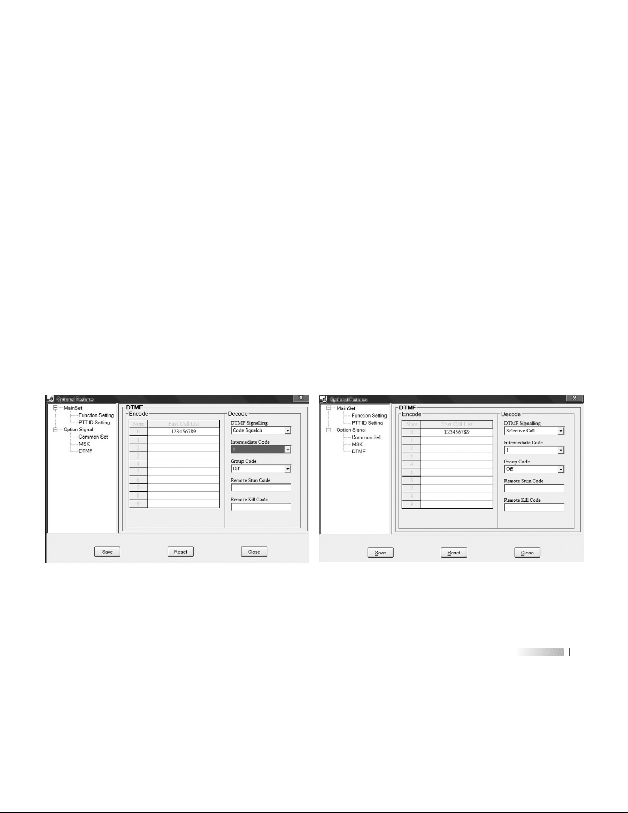
DTMF Part
Click in sequence “program•Optional Features•Optional Signal•DTMF”
Step 1: Edit the Fast Call list via programming software, radio can store up to 10 groups
(0-9) last calling list in total
Step 2: Input the desired code into the corresponding list, 16 characters in maximum.
Step 3: Choose the desired DTMF decoder from available values: “Code Squelch (Picture
1) and Selective Call (Picture 2)”
Step 4: Choose the Intermediate Code if you select “Selective Call” (The first three are ID
code and the fourth are Intermediate Code)
Step 5: Choose the group code, then click [save] after finishing it, and then exit.
Picture 1 Picture 2


5352
the one in the CallList, e.g.: if ID code is 1234, the corresponding callList is Group 1
(Picture 3)
Picture 3
Step 4: Set the optional signal of the desired channel to be MSK. Click “More” after every
frequency you edit, program it in the popup (Picture 4)
Picture 4


5554
Picture 5 and Picture 6,
Picture 5: 2tone as transmitting encoder
Group 0:2 tone
Group 1: single tone
Picture 6: 2tone as receiving decoder
Group 0:.2 tone decoder
Group 1: single tone decoder
As single tone calling, only input A Tone (e.g. A Tone is 1750 Hz), no need to input
in another Tone. The Tone in “Group Call” should be the same to the Tone of
encoder (900.3MHz).
Step 3: Set the optional signal of the desired channel to be 2-Tone. Click “More” after every
frequency you edit, program it in the popup. (Picture 7/8)
Picture 7: Select group 0 as 2-Tone Picture 8: Select group 1 as single-tone


5756
E.g. the self ID is CCIR2, 5tone is 2A358; the ID of other radio is 44044 (group number is
0). As following picture 9:
Picture 9
Click “Save” after editing desired 5tone, and then write into the radio
Click “More” after the channel needed editing to enter setting. Select 5tone in the Optional
signal, and then select the List Num want to call, and click “ON” in the Auto Response.
You also can set the frequency and channel then press “OK” to save the information to the
radio (Picture 10)
Picture 10


5958
If you want to use remote kill, stun, activate and revive, please program signalling for
current channel as DTMF and 2/5tone.
REMOTE KILL: If the radio received DTMF code programmed as remote kill, the radio will
enter the remote kill status; radio cannot send or receive signals. If the
radio received DTMF code programmed as revive, the radio will quit the
remote kill status and enter normal operation. In this situation, the radio
only can be revived by programming software, the method is as follows:
read data from radio first and then click program → Optional Features →
Optional Signal → Common Set, and select “Normal” in the “Remote Kill
Type”, then save the data to the radio.
REMOTE KILL, STUN, ACTIVATE AND REVIVE
REMOTE STUN: If the radio received DTMF code programmed as remote stun, the radio
will enter the remote stun status; radio can only receive signals and
cannot send signals. If the radio received DTMF code programmed as


6160
code, the radio will enter the remote stun status and you will hear a sound. And
then press [PTT] and input DTMF code 12345678#, the radio will quit the remote
stun status and enter normal operation. The operation of remote kill is the same to
remote stun, but in this situation, radio cannot be revived by this way.
B. press [ ], LCD displays ‘------‘, input the code directly and then press [PTT] to
transmit.
e.g.: the Remote stun code for radio A is 1234567, revive code is 2345678, remote kill
one is 7654321. If you want to remote stun it, please use another one, radio B to
input the working frequency of radio A, then press [ ], LCD displays “-----“, input
in sequence 1234567, then press [PTT] to transmit. After receiving this code, the
radio A will enter the remote stun status and you will hear a sound. If you want to
3) 5T&2T Version
A. Click in sequence “program → Optional Features → Optional Signal → 5-Tone →
Remote kill/stun code” to input your desired Remote kill/stun code, the fixed one is
7 characters.


User's Manual
TECHNICAL PARAMETERS
www.maas-elektronik.com


Transmitter
RF Sensitivity
Audio power
Audio Distortion
Intermediation
Selectivity
Spurious Rejection
Blocking
Receiver
6564
Note: Specification will be revised without notice due to technical improvement. Thank you.

 Loading...