


M2 Antenna Systems RC2800PX-AZ Service manual
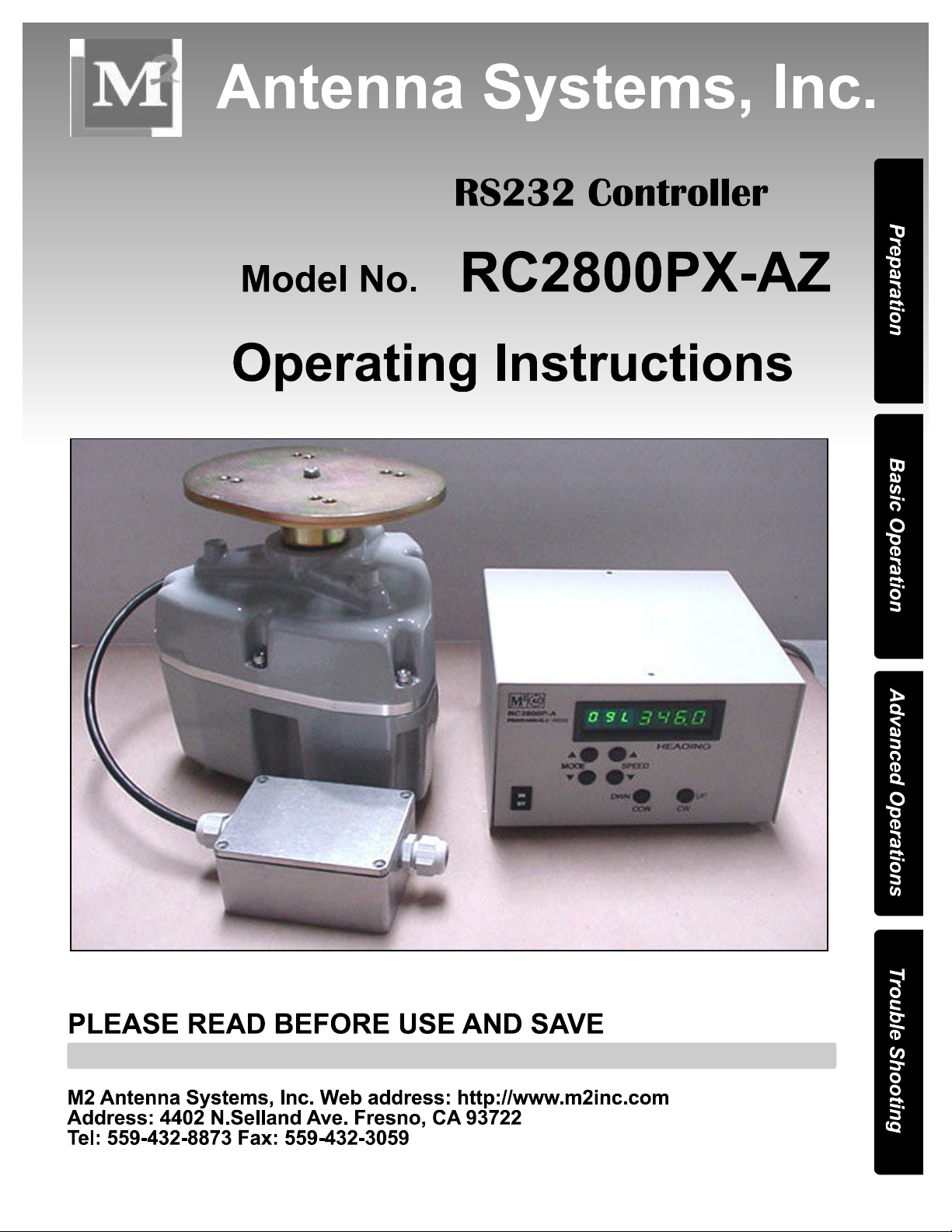

TABLE OF CONTENTS
4-23-03 REV 7-22-03
COVER PAGE
TABLE OF CONTENTS 2
FEATURES 3
GETTING STARTED 4
FRONT PANEL CONTROLS 5
RUN MODES 6
PROGRAMMING MODES & CALIBRATION 7,8
PROGRAMMING PRESETS 9
REAR PANEL AND INSTALLATION HINTS 10
OPERATION BY COMPUTER 11
AZ AND EL OPERATION BY COMPUTER 12
WRITING CONTROL SOFTWARE 13,14
TROUBLE SHOOTING 15,16
SIMPLIFIED THEORY OF OPERATION 17
WIRING AND PARTIAL PCB SCHEMATIC 18
WARRANTY 19

4-23-03
FEATURES
Our ALL NEW, GREEN LED, PIC rotator controller is packed with new features including
AUTO-CALIBRATE, AUTO SLOW DOWN as limits are approached, ONE STEP PROGRAMMING saving all changes by exiting the program mode. SOFTWARE UPDATES directly from our “m2inc.com” website Also included is increased circuitry and reed switch
protection. Of course computer control has also been improved. The new RC-2800PX
now accepts fractional inputs like 138.7 degrees and the Auto-calibrate command from a
computer or remote site. What we did not change is front and back panel layout so it
doesn’t require re-learning the controls and the actual operation is almost identical to the
old units. Everything is just a bit smoother and easier. The new PIC microprocessor lends
itself to easier custom programming for special rotator control functions. This custom program can be downloaded directly through the RS-232 port on your RC-2800PX from our
site on the WEB. Of course this new controller works with any of our older OR-2800DC rotators. It can also be easily modified to work with MOST of our older AC (OR-2800AC)
units as well. By ordering an RC-2800PPX controller this design can control a Prop Pitch
Rotator with all the same features. If you have a very custom rotator system using a large
AC or DC motor of almost any voltage or phase (like 3 phase 240 AC) the RC-2800PX
design can control your rotator system. This same controller also controls our line of Elevation rotators (Positioners) like the MT-1000, MT-3000, MT-4000 and the largest, MT-
5000. The Elevation controller can be linked to the AZ controller and both then can be
controlled by computer through a single RS-232 line. We also have a Dual controller (RC2800PRKX) in one rack mount case to control an AZ-EL system. The new RC-2800PX
controller it can handle any gear ratio from 1000 to over 50,000:1
Our OR-2800DC rotator is now supplied with a 60” PIGTAIL and a WATER TIGHT
HOUSING for a terminal strip. This creates an easy access, trouble free control cable
connection. Your control cable can have as few as 2 motor wires (see the “size VS distance” information later in manual) and a small single shielded lead for the position feedback.
4402 N. Selland Ave, Fresno CA 93722 (559) 432-8873 FAX 432-3059
www.m2inc.com Email: sales@m2inc.com
3
GETTING STARTED (with an OR2800 azimuth rotator)
We highly recommend that upon receiving the rotator and controller, you hook it up in the shack
and get used to the operation.
Here is what you do.
1. Connect the black lead in the rotator pigtail to terminal #1 on the back of the control box.
2. Connect the White wire to terminal #2. (AND ON AC UNITS, connect the RED wire to #3).
3. Connect the Orange wire to terminal #5.
4. Connect the Blue wire to terminal #6.
5. Unwrap the AC power cord and plug in the RC-2800PX controller.
6. Turn on the controller. The NEW green display should come up and read “0” “9” XXX .X
7. Push and hold in the UPPER mode button. “P20 0.0” should come up.
8. Bump the LOWER mode button SEVEN (7) times until you see “P0 CAL”
9. Push in the LOWER mode button and you will see the SEGMENTS of the digit to the left of
the “C” start to rotate counterclockwise at the same time the rotator is moving Counterclockwise
(CCW). Release the LOWER mode button and the rotator will continue going CCW by itself at
half speed. Soon the rotator will stop and the display will change to read “0 9 L346”. The rotator
and the control box are now in sync and CALIBRATED. THIS PROCEDURE CAN BE REPEATED ANYTIME IF YOUR CALIBRATION IS LOST, CHANGED OR SUSPECT. It can also be
done remotely from a computer. Normally, the only thing that can keep your RC-2800PX from
displaying the correct heading is IF your mast or antenna has slipped.
10. Now push the CW button and rotate the OR-2800 until the display reads 0.00 or close.
This represents TRUE NORTH, not MAGNETIC NORTH. The “antenna system” if one were
clamped to the top plate, should be pointed at TRUE NORTH and the mast clamps tightened.
YOU ARE NOW CALIBRATED. You should use the above procedure for your final setup too.
NOTE: Any known direction can be chosen for use in aligning the antenna to but you must run
the rotator to THAT heading PRIOR TO clamping the antenna in that direction. THAT’S IT. All
that is left to do is mount the rotator in the tower and connect up the control cable at both ends.
Clamp the antenna at the chosen heading as viewed on your RC-2800PX display and you are up
and running. More details on programming, presets, “South stop”, RS-232 interface, cable size
and possible shielding requirements and much more are on subsequent pages of this manual.
4
. 4-23-03
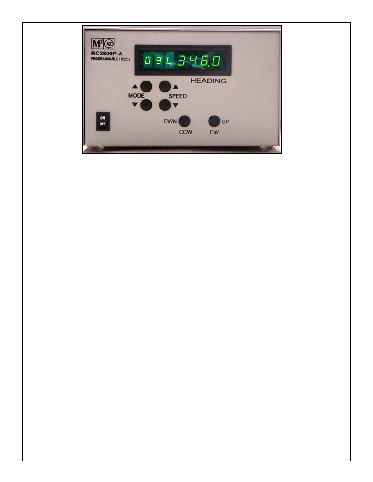
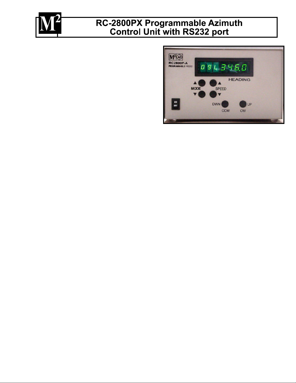
FRONT PANEL CONTROLS
“PWR” ROCKER SWITCH
Located in the lower left hand corner of
the front panel, this button controls AC
power to the unit.
DIGITAL DISPLAY
The digital display panel shows (from left
to right): MODE, SPEED, and
HEADING / PROGRAMMING data.
Display Digit:
#1: (full left): shows the selected MODE for operation or programming.
#2: Indicates the positioner travel SPEED in relative numbers from 0 to 9.
#3, Indicates, an ”L” for a Limit zone or a digit when programming in a high gear ratio.
#4, 5, 6, 7: Indicates HEADINGS, Azimuth or Elevation, in degrees and programming
data.
MODE BUTTONS
The Mode buttons are used to cycle through and select among 3 operational or "RUN"
modes, and 17 "PROGRAM" mode positions. See RUN MODES and PROGRAM
MODE details following this section.
“SPEED” BUTTONS
The speed buttons control the positioner's rate of speed in relative increments. "1" is
the slowest speed, "9" is the fastest. ‘0’ IS DISPLAYED WHEN THE ROTATOR IS
NOT MOVING. The top button increases the speed, the lower button decreases speed.
Lowest speed available DEFAULTS TO 1 but can be set to any number between 1 and
9 in program mode P5. Speeds can be altered for travel in any of the run modes, but
must be returned to speed 9 for full speed and full ramp functions.
“CW" (“UP”) and "CCW” (“DOWN“) BUTTONS
The "CW" and "CCW" buttons activate the positioner directly in Mode 0, Mode 1 and
Mode 2. These buttons also are used in the PROGRAMMING MODE to make
changes to factory defaults and for selecting preset headings.
NOTE: Throughout this manual you will see different words for the same item. Some
common terms would be: Sometimes we just get tired saying the same old thing.
RC-2800PX = Controller, Control box, box or unit.
DISPLAY = Readout, Heading,
ROTATOR = Positioner, Rotor
5

RUN MODE DESCRIPTIONS AND EXPLANATIONS
RUN MODES: Modes 0, 1, AND 2 are RUN modes that activate the positioner with manual or pre-
set commands. Momentarily push either MODE button to cycle through Modes 0, 1, and 2.
MODE 0: Manual operation mode. Pushing the CCW or DOWN button activates the rotator in the
COUNTER-CLOCKWISE direction and the HEADING count will go down. Pushing the CW or
UP button activates the rotator in the CLOCKWISE or UP direction and the HEADING count
will go up. The positioner runs while "CCW" or "CW" button is depressed, ramping up from
minimum programmed speed to the maximum (9) and stopping, WITHOUT ramp down, when
the button is released. When reversing direction there is a 2-3 second delay before posi-
tioner activation. This delay reduces stress on your antennas, tower and guy system.
NOTE:
Rotation direction, i.e., CW / UP or CCW / DOWN is defined as if you are looking down on
the rotator / antenna from above. There is no automatic speed ramp down when operating
in Mode 0 EXCEPT AS YOU APPROACH A LIMIT. Small movements of positioner may not
allow full speed to be reached.
(Special programming will soon be available at our web site (www.m2inc.com) that can be
downloaded directly into your RC-2800PX to reduce the ’reverse delay’ to .1 sec for special
applications). General updating will be available from the web site as well.
MODE 1: Computer control or Manual preset mode. When computer control is activated, a “1”
automatically appears in the MODE # location on the display. Manually the "CW" / UP and
"CCW" / DOWN buttons can be used to select a heading on the display from the full range of
rotation. AFTER the button is released, there is a short delay before positioner activation, allowing time to adjust or "bump" your selection. As the positioner begins to run, the speed
ramps up from the minimum programmed speed to the maximum. As the target heading is
approached, the speed ramps down to stop. The positioner may then "bump" several times
until within about .5 degrees of preset. To STOP or cancel a preset ANY TIME, TOUCH either mode button.
MODE 2: Programmable preset mode. Press the "CW" / UP and "CCW" / DOWN buttons to cycle
through 10 PRESET headings you program into Modes 20-29. Heading selections are shown on
display. After a short pause, allowing you to confirm you selection, the positioner will proceed to the
displayed heading the same as in MODE #1. Typically, these presets are programmed for frequently
used headings and / or stow positions for parking or extreme weather. TO STOP OR CANCEL A
PRESET IN MID TRAVEL TOUCH EITHER MODE BUTTON.
6