

M2 Antenna Systems 6M7 User Manual
SPECIFICATIONS
Model .....................................6M7
Frequency .............................49.5-50.5 MHz
Gain ........................................10.5 dBd
Front to back ..........................23 dB
Beamwidth E - Plane ...........E=42o / H=50o
Stacking Distance ..................24' Wide, 22' High
Feed Impedance / Conn. .......50 Ohms / “N” fem.
VSWR ....................................1.2:1 @ 50.1 MHz
Power Handling ......................1.5 KW
Match Type ............................‘T’ Match
Balun ......................................4:1 Coaxial
Lightening Protection .............All Elements Grounded
Boom Length / Dia .................26’ 9” / 2" O.D.
Element Type .........................1/4" Rod with 3/8” Sleeve
Mast Size ...............................2"
Wind Area / Survival ..............3 sq ft / 100 MPH
Weight / Ship Wt. ...................17 Lbs / 19 Lbs UPS
FEATURES
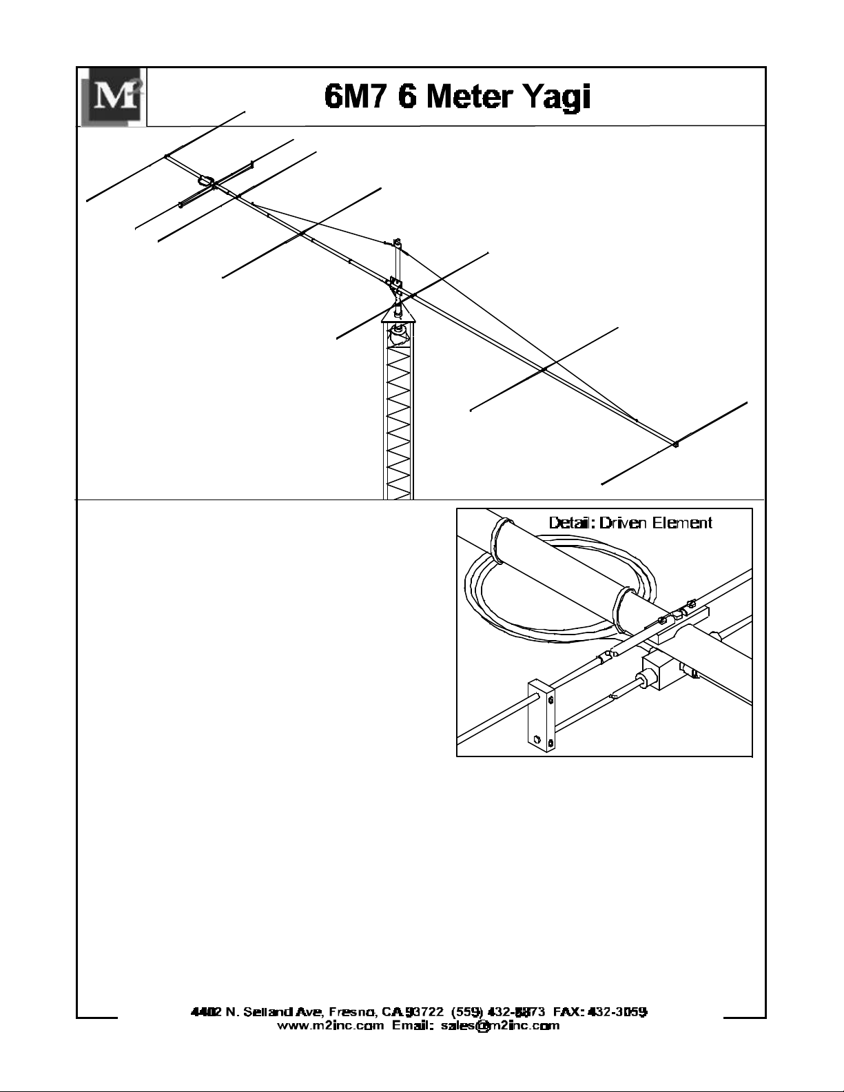
The 6M7 is a mid-sized 7 element antenna designed with the aid of computer technology to
produce maximum gain for its boom length. Features include machined aluminum element
mounting blocks, O-ring sealed connectors and balun, silicone-gel sealed “T” match block, and
stainless steel hardware. Elements are 1/4” aluminum rod with 3/8” tube center sleeves, and all
are DC grounded. An overhead guy system is provided for additional boom support.
TOOLS REQUIRED: Screwdriver, 11/32 wrench, socket or spintite, a 7/16" and 1/2" wrench or
socket, tape measure.
1. Layout the boom sections as shown on Dimension Sheet and assemble with 1/4-20 x 2-1/2” bolts
and locknuts. Note: the REAR boom section, #1, has the most holes. Section #2 has one element
mounting hole 36-1/2” from the swaged (necked down) end. Section #3 has one at 39-3/4” from the
swaged end. Section #4 is unswaged. Tighten the nuts securely.
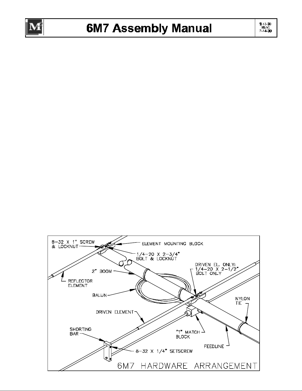
2. Use the Dimension Sheet as reference for ins talling the ELEMENT HALVES on to the ELEMENT
MOUNTING BLOCKS. U se the 8-32 x 1" screws and locknuts. Install screws from bottom of blocks.
3. Mount the longest element (REFLECTOR - 60-1/8” element halves) to the hole at the rear end of the
boom using a 1/4-20 x 2-3/4” bolt and locknut. Tighten securely.
4. Mount the DRIVEN ELEMENT next with a 2-1/2” bolt, threading it into the 'T' MATCH BLOCK held
to the underside of the boom. Orient the match block with the “N” feed connector pointed to the front.
Mount the DIRECTOR ELEMENTS using 1/4-20 x 2-3/4” bolts and locknuts.
5. Thread the gold SEAL NUTS all the way onto the two small connectors on the 'T' match block,
black neoprene side out. Then connect the balun connectors and tighten them GENTLY with a
7/16" end wrench. Now back out the seal nuts until they are up against the face of the balun
connectors and tighten them about 1/2 turn with a 1/2" end wrench. Secure coiled balun to boom with
two nylon ties.
6. Install two 8-32 x 1/4” Setscrews into each SHORTING BAR. Then slide a SHORTING BAR onto
each DRIVEN ELEMENT HALF and onto the 1/4” “T” match rods. Position so there is 17-3/8” between
the outer edge of the match block and the inner edge of the shorting bar (also see Dimension Sheet).
Align rods and element halves parallel and tighten the set screws with the 5/64" Allen wrench provided.
7. Install the feedline, mating and tightening the Male 'N' connector carefully. Route the cable forward to
 Loading...