

Page 1

BY ELIZABETH KAY LARSEN
VERSION 1.1 – DECEMBER 9
WWW.LZXINDUSTRIES.NET
TH
2014
1
Page 2
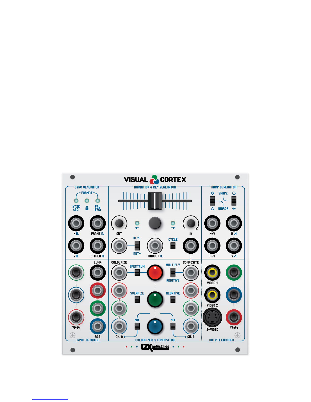
TABLE OF CONTENTS
DEAR VIDEO ARTIST .......................................................................................................................................................................................................................................... 3
TECHNICAL SPECIFICATIONS ................................................................................................................................................................................................................... 4
MODULE INSTALLATION .............................................................................................................................................................................................................................. 4
VIDEO SYNC CONNECTIONS ....................................................................................................................................................................................................................... 5
SYNC GENERATOR ................................................................................................................................................................................................................................................ 6
RAMP GENERATOR ............................................................................................................................................................................................................................................ 7
ANIMATION & KEY GENERATOR ....................................................................................................................................................................................................... 8
COLOURIZER & COMPOSITOR ................................................................................................................................................................................................................. 9
INPUT DECODER ..................................................................................................................................................................................................................................................... 10
OUTPUT ENCODER................................................................................................................................................................................................................................................. 11
EXPANSION & PROGRAMMING HEADERS .......................................................................................................................................................................... 12
WARRANTY ................................................................................................................................................................................................................................................................. 13
2
Page 3

DEAR VIDEO ARTIST
Acknowledgments
Product Design & Development
Elizabeth Larsen, Edward Leckie
Assembly Technicians
Jonah Lange, Heather Larsen, David Townsend, Saschenka Lopez
Manufacturing & Distribution
Joshua Holley, Rico Loverde, Paul Baker, Sarah Holley, Anna Sitko, and
everyone else at Darkplace Manufacturing in Portland, Oregon
Additional Graphic Design
Adam Fuchs, Hannes Pasqualini – Papernoise
Special Thanks
Johnny Woods, Jennifer Juniper Stratford, Sam Newell, Nick Bartoletti, Jason
Kylie Frame, Alex Peverett, Paul Millar and countless others
Our world moves rapidly at the pace of progress – ravenous for the highes t def ini ti on, the larges t disp lay,
and the fastest data transfers. In our hunger for new technology, we have left behind a vast expanse of
unexplored dimensions and forsaken possibilities.
But not you, Video Artist. You’re look ing in a differ ent direc ti on. Not ahe ad, not b ehi nd, but para lle l. Yo u
are a pilot, prepared to man the controls of a time machine.
Your video synthesizer is a retro-futuristic vessel outfitted to explore faraway vistas from the era of
analogue television. From your seat in the cockpit you will unveil prismatic motions, expose mesmerizing
geometries, and witness hypnotic entities never before seen. Swimming behind the diffused warmth of
the cathode ray glow, living images linger, waiting for you. It takes guts to do what you do – many will say
your path is absurd.
Thank you, Video Artist, for supporting our continuing efforts at LZX Industries to create new tools and
workflows for the timeless medium of analogue video synthesis. Visual Cortex marks a new generation of
our products, encapsulating several years of obsessed development and prototyping. While Visual Cortex
forms the foundation of a modular system, it is also a powerful tool on its own – everything you need to
learn the basics of video synthesis is right here.
Our work would not be possible without the pioneers of video art in the 1960s, 1970s and 1980s. These
wonderful human beings cast the first rays that continue to inform and inspire us, and we owe them our
gratitude: Bill Etra, Bill Hearne, Daniel Sandin, Dave Jones, Denise Gallant, Eric Siegel, Jim Wiseman,
Nam June Paik, Kim Ryrie, Peter Vogel, Phil Morton, Richard Monkhouse, Rob Schafer, Sherry Hocking
& Ralph Hocking, Shuya Abe, Stephen Beck, Stephen Jones, Steve Rutt, Steina & Woody Vasulka and
countless others. With our work, we endeavor to continue the legacy of these visionaries and their tools.
All of us here at LZX Industries send our love and excitement to you and your companions … we’re
counting on you, Video Artist. We can’t wait to see what you discover out there.
Over and out,
Elizabeth Kay Larsen
December 9th, 2014
Nanna, Tommy DOG Prinz, Jordan Bartee, Dan Green, Aaron White, Marcus
Webb, Todd Larsen, Paul Baker, Chad Allen, Malcolm Elijah Welbourne,
Stephi Duckula, Scott Jaeger, Chris King, David Wagenbach, Shawn Cleary,
3
Page 4
TECHNICAL SPECIFICATIONS
Mechanical
Width
26HP, 5.2 inches
Height
3U EuroRack Standard
Mounting Depth
1.75 inches
Power Connector
16-pin Male IDC Connector
Included Accessories
(4) M3 x 6mm Mounting Screws, (1) 16-pin EuroRack Standard Power Cable
Power
+12V Power Consumption
180mA
-12V Power Consumption
230mA
Inputs and Outputs
Internal Signals (3.5mm Jacks)
0-1V, DC Coupled, +/-12V tolerant, high bandwidth
0.5V threshold for trigger inputs
External Signals (RCA & S-Video Jacks)
1V after 75R input termination, AC Coupled, high bandwidth
FORMAT
NTSC/480i
PAL/576i
H Sync Frequency
15,734KHz
15,625KHz
H Sync Pulsewidth
4.7uS
4.7uS
V Sync Frequency
59.94Hz
50Hz
Frame Clock Frequency
29.97Hz
25Hz
Total Scanlines
525
625
Active Scanlines
480
576
Active Pixels
720
720
Frame Clock Frequency
29.97Hz
25Hz
Total Scanlines
525
625
Video Timing
MODULE INSTALLATION
1. Remove module, mounting screws, and power cable from their packaging. Visually inspect all pieces
to ensure there is no obvious damage, such as broken connectors.
2. Power down your synthesizer and disconnect the power cable from the wall outlet.
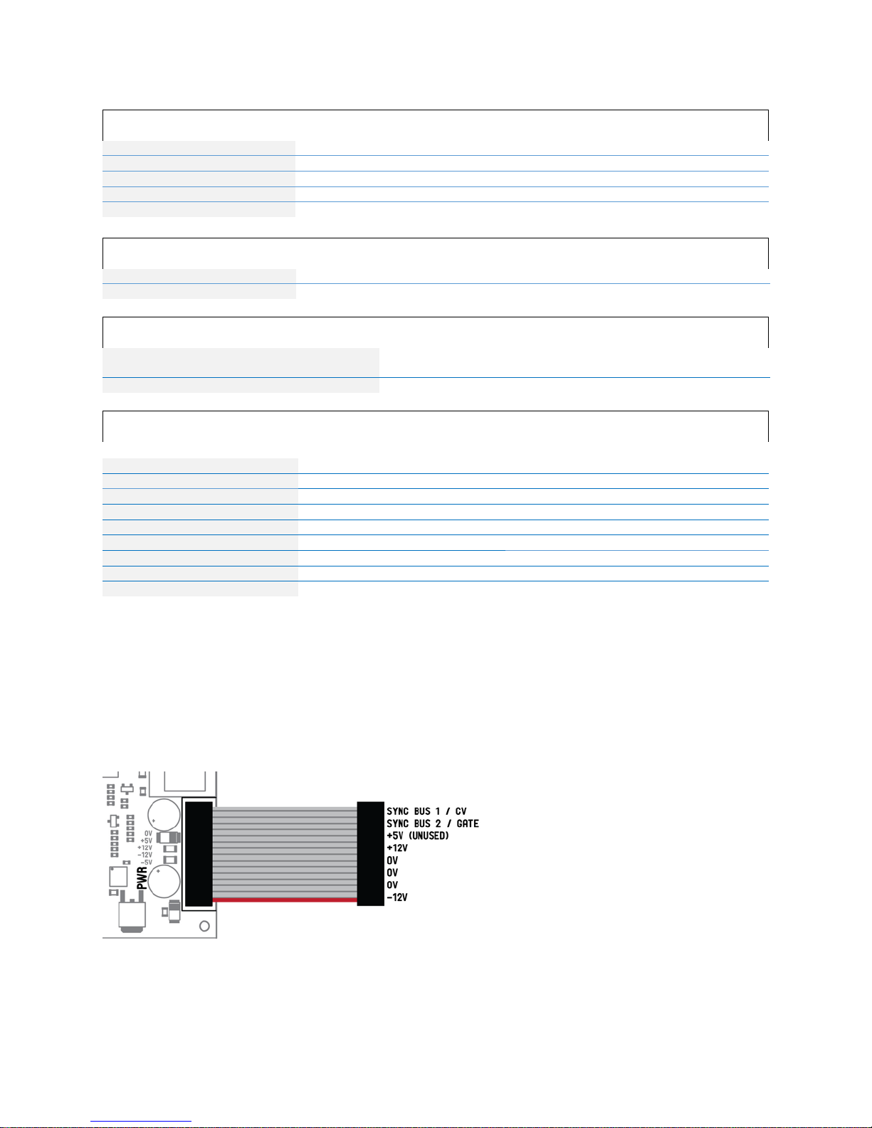
3. Attach the included power cable to the module’s power connector, then connect the other end to the
power distribution bus in your EuroRack synthesizer case as shown below.
4. Position the module on the mounting rails in your EuroRack synthesizer case and screw down all four
mounting screws. After double checking your connections, power your synthesizer back up.
4
Page 5

VIDEO SYNC CONNECTIONS
Connecting Additional Video Synthesizer Modules
Connecting External Video Input And Display Devices
When dealing with analogue video in a hardware environment, synchronization and timing is very
important. Any devices with video input and output connections must be synchronized to each other in
order to combine the video signals in the same domain. One device must serve as the synchronization
master, providing timing references for all the other devices. Typically, this device is the Visual Cortex.
Many video synthesizer modules require access to the synchronization signals. Previous releases by
LZX Industries used a 14-pin IDC cable to distribute these signals. The Visual Cortex includes an output
header in order to retain compatibility with these modules. Visual Cortex and future releases will use
standard video connectors to distribute synchronization timing.
Whenever an external video input is used with the Visual Cortex, one of two conditions must occur:
1) The external device must serve as the master source, slaving the Visual Cortex’s timing to its own.
2) Or, the external device must be genlocked and synchronized to the timing of the Visual Cortex.
Since most video devices do not have a genlock input feature, option 1 will be the most common case. In
the case of option 1, please ensure that the sync source selection switch on the rear panel (see the Sync
Generator section) is set to “Decoder,” so that synchronization will be derived from the Decoder input
rather than the rear panel sync input.
If additional video inputs are desired, consider purchasing the LZX Color TBC module. This module
provides composite video decoding and time base correction of an external source, meaning that genlock
is no longer a concern.
5
Page 6

SYNC GENERATOR
Frontpanel
Rear
Block Diagram
The Sync Generator section is a broadcast specification video sync generator which can operate in
NTSC/480i or PAL/576i timing formats. It can provide the master timing reference for an entire video
synthesizer system, and its timing may be synchronized to an external video source.
A. Sync Format LED Indicators. Indicates NTSC or PAL mode.
B. Sync Lock Status LED Indicator. Green when locked to external sync, red
when external sync is detected but no lock can be achieved.
C. Horizontal sync output jack. A pulse at the beginning of each video scanline.
D. Vertical sync output jack. A pulse at the beginning of each video field.
E. Frame rate clock output jack. A gate is turned on at the beginning of each odd
field (the start of a new frame), and off at the beginning of each even field.
F. Dither pattern output. A dithered pixel texture for shading video objects. The
spatial geometry of the texture is influenced by the selected Ramp Generator
modes.
A. Video format selection switch. Selects between NTSC/480i and PAL/576i video formats.
B. External sync source selection switch. Selects between Input Decoder or rear Sync In
C. Sync In jack. A video input for external synchronization.
D. Sync Out jack. A black video output containing only synchronization pulses.
E. 14-pin LZX Sync Distribution Bus output. A 14-pin sync output for providing sync to previous LZX
Industries products which require it.
F. Sync-to-Power Bus selection switch. When on, these switches send horizontal and vertical sync
pulses to the CV and Gate pins on the 16-pin power connector.
(C).
6
Page 7

RAMP GENERATOR
Frontpanel
Block Diagram.
Up
H & V outputs mirrored
Center
No outputs mirrored
Down
H output mirrored
Up
Logarithmic
Center
Linear
Down
Exponential
The Ramp Generator section is a dual synchronized waveform generator. It generates grayscale
gradients in horizontal and vertical outputs, with selectable output waveshapes. These signals provide
the basis for many shape and pattern generation techniques.
A. Mirror mode switch. Controls symmetrical mirroring (ramp-to-triangle).
B. Shape mode switch. Controls the waveshape of the outputs.
C. Horizontal waveform output jack.
D. Vertical waveform output jack.
E. Sum output jack. Horizontal and vertical waveforms summed together.
F. Difference output jack. Vertical waveform subtracted from horizontal waveform.
7
Page 8

ANIMATION & KEY GENERATOR
Frontpanel
Key Modes Off
Adds to the target value set by the slider control (A).
Key Modes On
Key generator input source.
Key Modes Off
Control voltage output
Key Modes On
High speed video logic output, 0V = low, 1V = high
Block Diagram
Key Modes Off
Sets target value 0-1V
Key Modes On
Sets output amplitude
Cycle Mode Off
Toggles inversion of target value
Cycle Mode On
Resets output waveform
The Animation & Key Generator section is a multi-function control voltage generator, designed
specifically for controlling transitions between two video images. It can function as a manual controller
with slew, a flip-flop based envelope generator, or a low frequency oscillator. The key function enables a
high-speed comparator, which generates a hard key image suitable for shape generation or luma keying.
A. Slider control. Action dependent on mode:
B. In time control. Sets the speed at which the output
voltage rises to the target value.
C. Out time control. Sets the speed at which the output
voltage falls to the target value.
D. LED indicators. Two color visual indication of target
value and output voltage.
E. Pushbutton switch. Action dependent on m ode:
F. Trigger input jack. On the rising edge of the input signal, the pushbutton
G. Primary Input jack. Function dependent on mode:
(E) action is triggered.
H. Primary Output jack. Output signal dependent on mode:
I. Key mode switch. Switches between positive key generator mode on (+KEY), key modes off (center)
and inverted key generator mode on (-KEY.) While key modes are on, the internally generated control
voltages become the key generator threshold.
J. Cycle mode switch. Turns automatic cycling mode on or off.
8
Page 9

COLOURIZER & COMPOSITOR
Frontpanel
Block Diagram
Multiply
(A*B)+((1-B)*VC)
Fade (center)
(A*(1-VC))+(B*VC)
Sum
A+((-B*(1-VC))+(B*VC))
VC = Composite input signal (C).
0V – 0.5V
Red
0%
Green
0% to 100%
Blue
100% to 0%
0.5V – 1V
Red
0% to 100%
Green
100% to 0%
Blue
0%
The Colourizer & Compositor section is a voltage controlled analogue video mixer. It features two RGB
input channels, individual RGB controls and several advanced colour processing effects. We designed
this section to be capable of addressing all the essential colour mixing required for a small to medium
sized modular video synthesis system. The output of this section is sent directly to the Output Encoder.
A. Channel A RGB input jacks. RGB inputs to Channel A.
B. Channel B RGB input jacks. RGB inputs to Channel B.
C. Composite input jack. Voltage control over the selected
Composite mode
D. Composite mode switch. Selects formula used to
combine Channel A
E. RGB colour controls. Clockwise rotation adds the
selected colour, while counterclockwise subtracts.
F. Colourize input jack. Voltage source of the RGB colour controls
G. Mix A on/off switch. Adds the output of the RGB colour controls
H. Mix B on/off switch. Adds the output of the RGB colour controls
I. Spectrum on/off switch. Translates the value of the Colourize input
J. Solarize on/off switch. Inverts all color values below 0V.
K. Negative on/off switch. Subtracts all color values from 1V.
(D).
(A) and Channel B (B):
(E). Connected to 1V by default.
(E) to Channel A (A).
(E) to Channel B (B).
(F) to colour channels:
9
Page 10

INPUT DECODER
Frontpanel
Block Diagram
The Input Decoder section is an analogue video input amplifier and colorspace converter. This section
accepts YPbPr analogue component video, and processes it for patching internally inside a video
synthesis system. The Y input can be used with Composite video signals if only grayscale operation is
desired.
A. Component YPbPr input jacks. Component YPbPr video inputs for external
video gear. If no Component source is available, a Composite (NTSC/PAL CVBS)
signal can be input to the Y jack independently. In that case, only grayscale video
will be passed to the outputs.
B. Luma output jack. This output is full scale video representing the grayscale
brightness of the source video signal.
C. RGB output jacks. These jacks output the Red, Green & Blue color channels of
the source video feed when a Component YPbPr source is used.
10
Page 11

OUTPUT ENCODER
Frontpanel
Rear
Block Diagram
The Output Encoder section takes the output of the Colourizer & Compositor section, converting
signals inside your video synthesizer into standard video signals which may be displayed and recorded.
A. Composite video CVBS output jacks. Both jacks output identical video
signals.
B. S-Video Y/C video output jack. Separate luma (Y) and chroma (C) signals to
S-Video format Mini DIN 4 jack.
C. Component YPbPr video output jacks. Component video outputs for the
highest quality full color analogue signal path.
A. Black Level Adjustment trimmer. Adjusting this trimmer will adjust the
brightness level of all the encoder outputs when calibrating for displays and
recording devices.
11
Page 12

EXPANSION & PROGRAMMING HEADERS
Rear
1, 3, 5, 7, 9, 11, 13, 15
GND
2
Output Encoder, S-Video Y Out
4
Output Encoder, S-Video C Out
6
Output Encoder, CVBS Video 1 Out
8
Output Encoder, CVBS Video 2 Out
10
Output Encoder, Component Y Out
12
Output Encoder, Component Pb Out
14
Output Encoder, Component Pr Out
1, 2, 3, 5, 7, 9, 10, 11,
12, 13, 15
GND
4
Input Decoder, Component Y In
6
Input Decoder, Component Y In
8
Input Decoder, Component Y In
14
Sync Generator, External Sync In
16
Sync Generator, External Sync Out
Visual Cortex contains many connectors accessible via the rear of the module. LZX Industries will not
offer technical support or service for use of these headers, but savvy users may be able to tap into them
and find them useful for custom applications.
A. JTAG programming header. For uploading firmware to the Xilinx XC2C256.
B. AVRISP programming header. For uploading firmware to the AVR Atmega32A.
C. Video IO connections header 1. For wiring external connectors.
D. Video IO connection s head er 2. For wiring external connectors.
E. RGB expansion header. Direct access to the RGB channels before encoding.
12
Page 13

WARRANTY
This product is covered by LZX Industries’ warranty, for one year following the date of manufacture. This
warranty covers any defect in the manufacturing of this product. This warranty does not cover any
damage or malfunction caused by incorrect use – such as, but not limited to, power cables connected
backwards, excessive voltage levels, or exposure to extreme temperature or moisture levels.
The warranty covers replacement or repair, as decided by LZX Industries. Pleas e c ontac t customer
service via our website (http://www.lzxindustries.net
The cost of sending a module back for servicing is paid for by the customer.
) for a return authorization before sending the module.
13
 Loading...