

Page 1

1. CONTENTS
2. SPECIFICATIONS
2.1 Technical specifications
2.2 Dimensions
2.3 Accessories
3. GENERAL DESCRIPTION
4. INSTALLATION
4.1 Mains voltage selection
4.2 Connectors
5. OPERATION
5.1 Power
5.2 Tape deck commands
5.3 Start-Stop muting
5.4 Record
5.5 Tape timer
5.6 Search
5.7 Speed display
5.8 Edit facilities
5.9 Variable wind speed
5.10 Edit cue
5.11 Tape cutter
5.12 Splicing block
5.13 Playing tape loops
5.14 Pencil edit
5.15 Speed selector
5.16 Volume
5.17 Headphone output
5.18 Monitor loudspeaker
5.19 Reel size
5.20 Reel types
5.21 Optional settings
6. OPTIONS
6.1 VU-meter bridge
6.1.1 Installation of meter bridge
6.1.2 Adjustment of meter bridge
7. SERVICE and ADJUSTMENTS
7.1 Playback level
7.2 Audio block diagram
7.3 Playback frequency response
7.3.1 Sync adjustments
7.4 Bias adjustment
7.5 Record level
7.6 Record frequency response
7.7 Phase shift adjustment
7.8 Erase adjustment
7.9 Bias traps and DC currents
7.9.1 Output amplifier DC current
7.9.2 Output amplifier bias trap
7.9.3 Playback preamplifier bias trap
7.9.4 Sync preamplifier bias trap
7.9.5 Record amplifier bias trap
7.10 Bias traps, location
7.11 Tape tension servo sensor
7.12 Reel motor control amplifier
7.13 Servo mix amplifier
7.14 Servo limit detector
7.14.1 Tape end stop adjustment
7.14.2 Tape load adjustment
Page 2

7.14.3 Elapsed time counter
7.15 Edit and start enable
7.16 Reel motor commander
7.17 Tape motion sensor
7.18 Capstan speed detector
7.19 Capstan driver amplifier
7.20 Capstan output amplifier
7.21 Headphone and speaker amplifier
7.22 Pinchroller driver
7.23 Tape lift driver
7.24 Counter opto amplifier
7.25 Parking brakes adjustment
8. SPARE PARTS
9. APPLICATION NOTES and SERVICE BULLETINS
10. DIAGRAMS
Page 3

2.1 TECHNICAL SPECIFICATIONS LYREC STUDIO RECORDER TYPE TR55
Max. unclipped output level +24 dBm into 200
==================================================================
TR55 1/4" TR55-MM 1/2"
Tape format: 1/4" 1/2"
Track format: NAB or DIN stereo 2/4 track
Tape speeds: 38.1 and 19.05 cm/s 9.5 and 19.05 cm/s
Long term speed
stability: < 0,1 % < 0,1 %
Varispeed: +/- 33 % +/- 33 %
Tape drive: Direct DC drive Direct DC drive
Reels: Up to 14 Up to 14"
Reel types: NAB, DIN or CINE NAB
Wind speed: max 500 ips/1270 cm/s max 500 ips/1270 cm/s
Wind time: ca. 80 s for 1000 m tape
ca. 60 s for 2400 ft tape
Stop time: < 3 s from wind < 3 s from wind
Start time: < 200 msec < 200 msec
Tape tension: 80 p +/- 20% (play) 80 p +/- 20% (play)
<175 p any other mode <175 p any other mode
Wow & Flutter: <0.04 @ 38 <0.07 @ 19
(RMS wtd) <0.07 @ 19 <0.12 @ 9
Timer accuracy: +/- 0,1% +/- 0,2%
Line input: Balanced and floating. Input impedance 10
kohms. -10 to +24 dBm input level (adjustable)
to produce 320 nWb/m tape flux.
Line output: Balanced and floating. Output impedance < 40
ohms.
Nominal level: 510 nWb/m=+6 dBm 320 nWb/m=+6 dBm @ 19
250 nWb/m=+6 dBm @ 9
ohms.
Equalisation: NAB or CCIR NAB
Bias system Optional Dolby HX Pro Dolby HX Pro
S/N: 64 dBA @ 510 nWb/m 60 dBA @ 320nWb/m
Frequency response: 31-19000 Hz +1/-3 dB 31-18000 Hz +1/-3 dB
Crosstalk: >40 dB @ 1 kHz >60 dB @ 1 kHz
Erase efficiency: >75 dB @ 1 kHz >75 dB @ 1 kHz
Connectors: XLR-type XLR-type
Power requirements: 90 - 130V :+/-10% 90 - 130V :+/-10%
200 - 240V :+/-10% 200 - 240V :+/-10%
50/60 Hz, 280 VA 50/60 Hz, 280 VA
Weight: Tapedeck: 39 kg Tapedeck: 39 kg
Floorstand 20 kg Floorstand 20 kg
Working conditions: Ambient temperature range: +10 - +40 C
Humidity range : 30 - 90%
Tape dependent specifications refer to BASF 911 or equivalent tape at stated flux. The specifications are
subject to change without notice. We reserve the right to make technical modifications without prior notice as
technical progress may warrant.
Small differences in component values or circuitry may be found between diagrams and actual
electronics. If these changes are of major importance for performance, revised diagrams will be forwarded when
printed.
Only figures with tolerances or limit can be considered guaranteed data. Figures without tolerances are
informative data, without guarantee (IEC 278, section 5.4 note).
No part of this manual may be reproduced without written consent.
Page 4
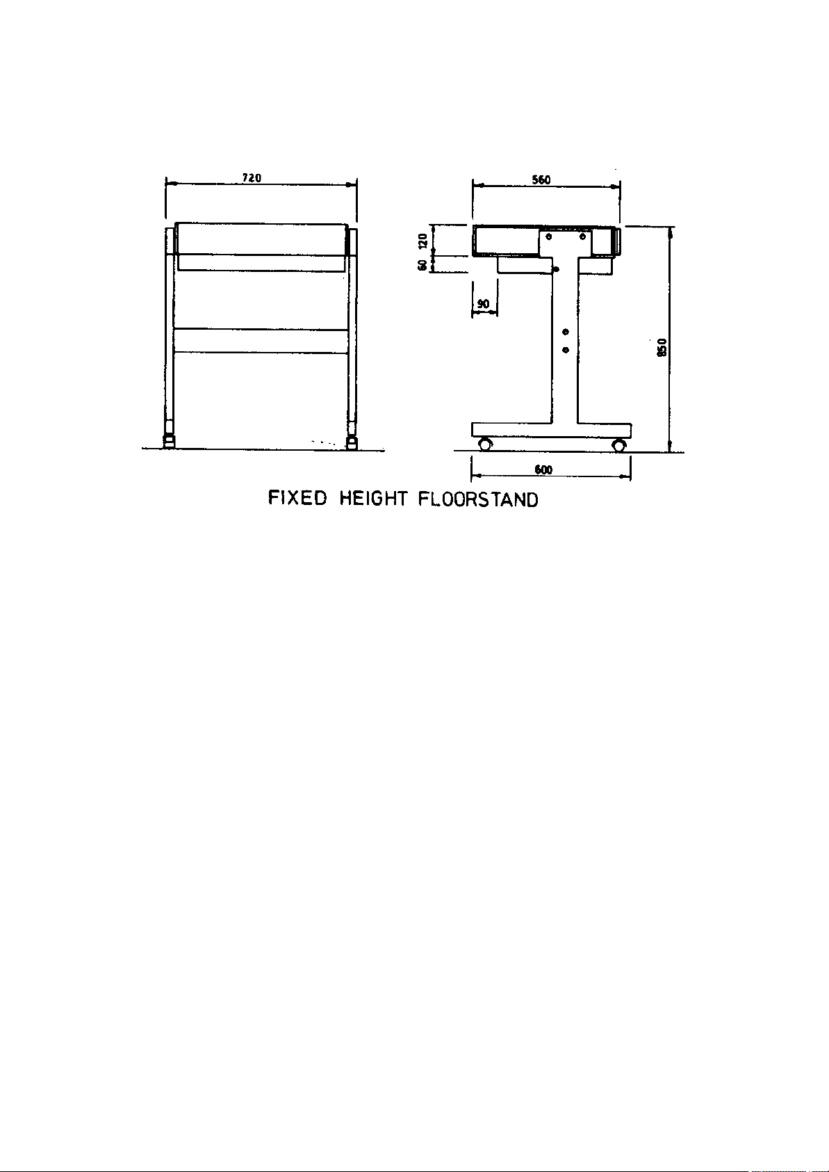
2.2 DIMENSIONS
Page 5

2.3 LIST OF ACCESSORIES
Page 6

3. GENERAL DESCRIPTION
The TR55 range of tape decks are expressly designed for the
professional user, it has exceptionally fast and precise tape
handling with astounding control times.
The TR55 tape deck is available for 1/4 or 1/2 inch tape as well
as 0.15" cassette tape (special manual apply).
All tape deck controls are located in a single row at the front of
the tape deck.
Full logic allows pushbuttons to be activated in any sequence.
The tape deck is all DC powered with double acting servoed reel
motors. The reel motors operate in a push pull system, i.e. bi directional drive. A servomix amplifier controls the interaction
between reels so that tape tension is kept constant in all
situations. Also during extreme modes like stop, reversing and
braking sequences.
Continously variable winding speed from stand still to 500 ips.
All types of reels and reel sizes up to 14" diameter can be used
in any combination.
Page 7
4. INSTALLATION
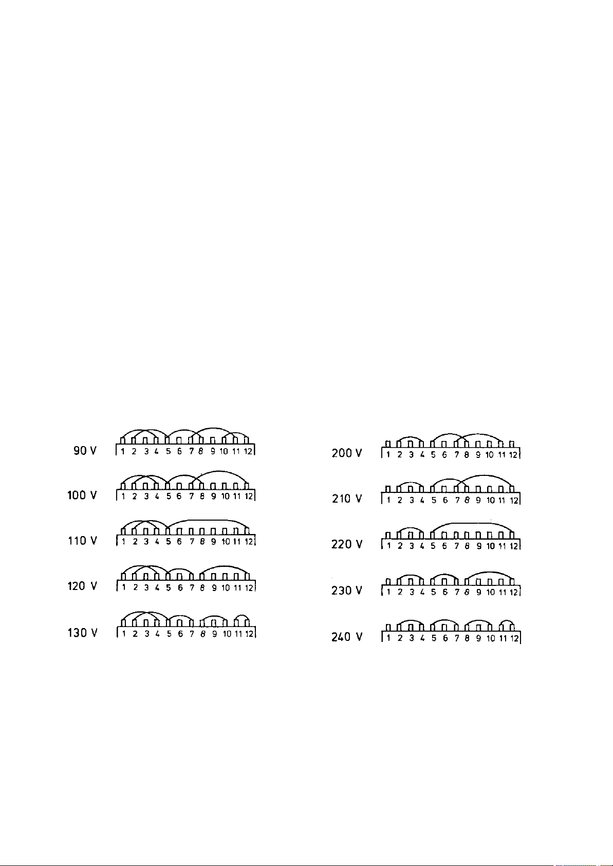
4.1 MAINS VOLTAGE
Before connecting mains to the recorder, control that the power
supply is wired for the correct mains voltage.
The mains transformer has two main windings, and two 10 V
windings. By connecting the windings in series and/or parallel,
the following mains voltages can be used;
90 - 100 - 110 - 120 - 130 V
200 - 210 - 220 - 230 - 240 V
The voltage selector is found close to the mains transformer. To
get access, it is necessary to remove the power supply.
1) Dismount the two 25 pole connectors marked "Remote Control"
and "Slave Display" from the back panel.
2) Disconnect both left and tight reel motor power amplifier.
3) Disconnect the flat cable feeding power from the power supply
and into the recorder.
4) Unscrew the four screws found in the extreme corners of the
back panel.
5) The complete power supply can now be pulled out backwards and
the voltage selector will be accessable.
Page 8

Rear panel connectors:
LINE IN: Pin 1 Ground
Pin 2 Signal live
Pin 3 Signal neutral
LINE OUT: Pin 1 Ground
Pin 2 Signal live
Pin 3 Signal neutral
AUXILLIARY SYNC OUT:
RECORD INDICATION: Pin 1 +24 volt when channel 1 is in record.
Pin 2 +24 volt when channel 2 is in record.
Pin 3 Ground
AUDIO REMOTE CONTROL: In/out puts to optional VU meter panel
SLAVE DISPLAY OUTPUT: Output for optional slave timer display
See drawing 9716 for pin configuration.
REMOTE CONTROL: See drawing 9750 for pin configuration.
VARISPEED: See drawing 9750 for pin configuration.
CHASSIS-0 VOLT: Ground link connecting MAINS SAFETY GROUND
(CHASSIS) with AUDIO GROUND (O V).
Page 9

5. LYREC TR55 OPERATING INSTRUCTIONS.
5.1 POWER
Connect the recorder to 220V, 50 or 60Hz. for other voltages,
special instructions apply.
Switch power on. The mains switch is located in the center of the
grid, extending the front plate to the rear.
When power is switched on, the tape timer is automatically set to
zero and tape speed selected to high speed. (NOTE: See customer
options).
The stop button will show a flashing light to indicate that the
tape is not loaded. (NOTE; See customer options).
Load tape according to drawing 1, where the tape path is shown.
After threading the tape, tape tension can be activated by:
a) Selecting START, WIND or EDIT-WIND.
Make sure the tape is loaded properly without any loops before
giving any command.
b) Manually "stretching" the tape with one hand on each reel.
After half a second tape tension will be activated.
(NOTE: See customer options.)
When tape tension is activated, this is indicated by a steady
illumination of the STOP button.
The two tape tension servo sensors are of a low inertia type and
therefore have a protective cover. The servo sensors control the
reel motors to operate in both directions.
WARNING!! Do not tamper with the tape in any way that will cause
the servo arms to change position. This will
immediately make the reel motors spin.
Do not activate START or WIND functions when tape is
not properly loaded.
5.2 TAPE DECK CONTROLS
The basic tape deck controls consist of five illuminated push
buttons controlling START, STOP, RECORD, REWIND and FAST FORWARD
WIND.
The controls are logically interlocked and can be operated in any
sequence.
A few features should be noted. The maximum WIND speed is
internally limited to 500 ips. The wind speed can be set to a
lower value (internal switch) if required, to suit the winding
properties of different tape brands.
The tape lifters in the headblock are activated by servo
controlled solenoids. The tape lifters are activated in wind when
the tape reaches an internally set tape speed (normally set to 60
ips.)
Page 10

The pinchroller is also operated by a servo controlled solenoid
and apart from in- and out position, it stays in a stand-by
position close to the capstan shaft in stop mode.
5.3 START - STOP MUTING
The output of the audioamplifiers are opened in STOP mode. When
the tape is started, the amplifier are automatically muted until
the tape reaches nominal tape speed. When going from START to
STOP, the amplifiers are again muted during the deceleration.
(NOTE: See customer options.)
5.3 RECORD
Record is activated by simultaneously pressing START and RECORD,
and erase and recording takes place first when the tape reaches
nominal speed.
When record mode is entered with running tape, erase and record
starts immediately.
5.4 TAPE TIMER
The tape timer is fed from the left tape guide roller. The display
shows hours, minutes and seconds correctly at both tape speeds.
Half seconds are indicated by a flashng dot. When rewinding
through zero, the timer counts positive but with negative prefix.
With the RESET button the timer can at any time be set to 00,00.
5.5 SEARCH
Connected to the tape timer is a search system allowing search to
either zero or one cue position. The cue position is set by
pressing the button CUE. The cue position is defined at the moment
the CUE button is pressed.
When later pressing SEARCH CUE, the tape will wind to the last
memorized position.
During search the START button can be pressed. The tape will then
go into play when the tape reaches the searched position,
5.6 SPEED DISPLAY
When the tape is running in any mode, the display can be switched
to read actual speed in IPS as sensed by the left guide roller.
I.e. the display does not show capstan speed but actual tape
speed.
The speed display is activated by pressing down the illuminated
speed selector button. When the button is released, the display
goes back to tape timing without "loosing" any time during the
speed readout.
5.7 EDIT FACILITIES
The EDIT button has several functions;
a) When the EDIT button is pressed (in STOP mode), the amplifiers
are demuted and the left tape lifter is activated. Tape tension
is deactivated and the recorder is ready for manual editing.
b) DUMP MODE. Pressing START while EDIT is held down, deactivates
Page 11

the take-up motor system to obtain dump mode. The tape timer is
active also in dump mode.
c) ANTI DUMP MODE. To play the tape from the waste basket and onto
the take-up reel, press the START button and keep it depressed.
Make sure the tape does not pass the left tacho idler as this
will activate the left reel motor.
5.8 VARIABLE WIND SPEED - EDIT WIND
The lever to control the variable wind speed is found next to the
EDIT button. The speed control is touch sensitive and can only be
activated by simultaneously holding down the EDIT button and
touching the speed control lever. EDIT wind speed is indicated by
illumination of both wind buttons and the EDIT button.
When the speed control is active, the winding speed can be
continously varied from full rewind to max forward wind and any
speed between. Each setting of the speed control, represents a
fixed speed.
EDIT WIND can be entered from any mode but can be cancelled by
STOP, START or SEARCH.
5.9 EDIT CUE
In winding and varispeed winding, the tape can momentarily be
brought in contact with the playback head by pressing the EDIT
button. This operation also demutes the amplifiers.
5.10 TAPE CUTTER (OPTIONAL)
The tape cutter is a mechanical device mounted inside and below
the headblock. The cutting takes place in front of the playback
head gap, which eliminates the need for a tapemarker.
To cut in front of the playback head it is necessary to lift the
tape from the head and into cutting position. A tape lifter is
automatically activated when the tip of the tape cutter mechanism
is touched.
Cutting can be done in EDIT, STOP or EDIT WIND mode.
a) Tape cutting in STOP or EDIT WIND mode.
Locate the cutting position by rocking the reels, either
manually (STOP mode) or with the EDIT WIND lever (EDIT WIND
mode).
When the edit wind lever is in center position the tape will
not move.
The cutting lever (located on the rear of the headblock) is
touch sensitive and when touched, the right tape lifter is
activated. The lever is now pressed further to activate the
cutter.
Do not press the cutting lever too fast. It is necessary to
allow sufficient time so that the tape lifter has reached its
position before the cutting takes place.
b) Tape cutting in EDIT or UNLOAD mode.
When EDIT is selected, tape tension is deactivared,
corresponding to unload mode. The cutting position can now only
Page 12

be found by manually rocking the reels. Cutting is made as
described above. Without tape tension the tape is held in
position only by the mechanical parking brakes.
5.11 SPLICING BLOCK
A splicing block is located on top of the headblock. It has three
cutting slots 45, 60 and 90 degreeswhere the 45 degree slot
corresponds to the built in cutter.
In order to firmly hold all kinds of tape the tape groove is
slightly curved and the sides have small protruding dovetails.
The proper way to remove the tape after splicing, is to hold both
tape ends and pull the tape which will then snap up out of the
groove.
5.12 PLAYING A SHORT PIECE OF TAPE WITHOUT REELS - PLAYING TAPE LOOPS
During editing it is sometimes desired to play a piece of tape,
which is too short to be loaded the normal way.
Place the tape in the tape path but not around the left tape
idler. Select EDIT and then START. Back tension must be obtained
by holding the tape with the left hand. As long as the left tacho
idler is not turning, the left reel motor will stay neutral.
To play an endless loop, the tape must be threaded so it does not
pass the left tacho idler or the servo arms. Back tension must be
obtained by manually keeping the tape stretched.
5.13 SOUND ON SOUND EDIT (PENCIL EDIT)
By using the left tape lifter it is possible to fade in a new
recording on an earlier recording.
In playback select EDIT, which will activate the erase/record head
tape lifter. It is now possible to select RECORD without actually
record, as the tape is lifted from the erase and record heads.
The tape lifter can now be defeated and the tape faded in by
pressing START. Pressing EDIT will again activate the tape lifter.
5.14 SPEED SELECTOR
Tape speed is factory set to 15 ips when power is switched on.
Switching to 7 1/2 ips can only be done in STOP mode. (NOTE: See
customer options.)
5.15 VOLUME
The volume control lever controls the monitor volume for either
headphones or the built in loudspeaker. The volume control does
not affect the line output level.
5.16 HEADPHONE OUTPUT
A 1/4" stereo headphone output is found to the far right of the
frontpanel. Connecting a headphone disconnects the built in
loudspeaker.
5.17 MONITOR LOUDSPEAKER
Page 13

A small loudspeaker is built into the frontpanel. The loudspeaker
reproduces the sum of both tracks. The loudspeaker can only be
turned off by setting the volume control to minimum or by
connecting a headphone.
Note: The signal to noise ratio of the headphone/speaker output is
lower than that of the line output.
5.18 REELSIZE
As factory supplied, the LYREC TR55 accepts any reel from 1/4"
diameter up to 12" (i.e. 1000 meter reels). Tape tension is kept
constant with any combination of reel sizes.
The reel motor systems are eccentrically mounted and can be turned
180 degrees by loosening 4 screws. In this position the tapedeck
accepts up to 14" reels.
5.19 REEL TYPES
The reeladapters are fixed to the reel platform with a snap-lock
device. Three types of adapters are available;
- NAB
- CINE/DIN
- AEG/DIN with or without platter.
5.20 CUSTOMER SELECTABLE OPTIONS
Inside the recorder a DIL-switch is found, where it is possible to
select some options. The DIL-switch is located on the tape deck
logic motherboard. The motherboard is mounted on gliders and can
be pulled out together with the frontpanel after loosening the
locking screw with a 3 mm Allen key.
1. AMPLIFIER MUTING AT STOP
Position ON: The audioamplifiers are muted in stop mode and
reactivated when the tape reaches nominal tape
speed.
OFF: The amplifiers are activated also in stop mode, and
only muted during acceleration and deceleration of
capstan motor and in WIND mode.
2. MANUAL ACTIVE STAND-BY TENSION
Position ON: When the recorder has lost tape tension, i.e. after
edit or tape end, the tape tension can be restored
by manually "stretching" the tape with one hand on
each reel. Tapetension is also automatically
reactivated when going to START, WIND ot EDIT WIND.
OFF: Tape tension can ONLY be reactivated by going to
START, WIND or EDIT WIND.
3. DYNAMIC BRAKING INHIBIT
Page 14

Position ON: The dynamic braking is switched off, resulting in
very long braking time. This is mainly a service
function to be used in the case the motion sensing
system should fail.
OFF: Dynamic braking is active.
4. TAPE LIFTER DEFEAT
Position ON: The playback tape lifter function is defeated in
EDIT WIND mode resulting in constant tape to head
contact.
CAUTION: Fast wind with constant head to tape contact will
wear out the playback head in a short time.
Position OFF: Tape lifter always lifts the tape at a preset speed.
5. SPEED PRIORITY
Position ON: Low speed priority makes the recorder always select
low speed when power is switched on.
OFF: High speed is always selected when power is switched
on.
6. FLASHING STOP LIGHT
Position ON: STOP lamp will show a flashing light to indicate
that tape is not properly loaded and tape tension is
not activated.
OFF: STOP lamp will always show steady light.
Switches 7 and 8 are not used.
7. WIND SPEED SETTING
Located on pcb EDIT WIND LOGIC is a switch that allows the user to
set the maximum WIND/REWIND speed to either 500 or 300 ips.
Page 15

6. OPTIONS and ACCESSORIES
6.1 VU-METER BRIDGE, TYPE TR55/AM77 #414010
The VU-meter bridge enables the user of the TR55 recorder to;
- Monitor on VU-meters and adjust the input and output levels
to/from tape.
- Select and adjust variable tape speed
- Record indication.
Note that controls/indicators for channel 2 are omitted in mono versions.
METERS: PRE/POST select whether VU-meter are connected to
recordside (PRE) or playback-side (POST). In PRE the
meters indicate the level sent to tape, in POST the
level sent to the output connector.
REC: Indicates if recording is active on that channel.
LEVEL: The CAL/VAR switches select, independent for the two
channels, if the INPUT/OUTPUT LEVEL controls are
active. In CAL, the input/output relations are as set
up by the internal adjustment of the amplifier; in VAR
the controls determine INPUT and OUTPUT LEVEL, with a
range of approx. +10 dB to -50 dB referred to CAL position.
TAPE SPEED: The CAL/VAR switches select whether tape speed is
controlled by the internal adjustment (CAL) or
controlled by the two adjustments COARSE and FINE
(VAR). In VAR the red LED gives a warning that an
abnormal situation exists. The adjustment range is
from approx. half to double the selected nominal
speed, and the exact speed may be checked by the
built-in speed display function of the tape deck.
6.1.1 INSTALLATION PROCEDURE FOR VU-METER BRIDGE, TYPE TR55/AM77
1. Remove the four distance-pieces, 1 on fig. 1, accessing the
screws with a 4 mm Allen key through the holes 2 on fig. 1.
2. Screw the distance-pieces on the rear of the tape deck.
3. Mount the meter bridge onto the distance-pieces.
4. Connect the plug emerging from the bridge.
5. Substitute the amplifiers installed with the ones following the
VU-meter bridge, using the original equalizer plug-in prints.
6. Go through the adjustment procedure.
NOTE: The recorder will neither record nor playback if the cable
is not connected.
6.1.2 ADJUSTMENT PROCEDURE FOR VU-METER BRIDGE, TYPE TR55/AM77
NOTE: All adjustments should take place with LEVEL-switches in
CALibrated position.
1. Since the AM77-amplifier has been modified for VU meter
operation, it is necessary to go through the normal adjustment
of AM77.
2. To adjust the VU-meters, remove the rear-plate of the box.
3. Adjust the meters to 0 reading with the disired level in (and
out) using the potentiometer on the board attached to the
meter. The left potentiometer sets the deflection with METER
switch in position PRE, the right one sets meter deflection in
Page 16

position POST.
4. Reinstall the rear-plate, and the adjustment is completed.
6.1.3 DESCRIPTION OF CHANGES TO THE AM77 AMPLIFIER WHEN USED WITH VU METER BRIDGE.
The following changes have been made on the AM77-amplifier to
enable the use of the variable gain in the VU-meter bridge, refer
to drawing no. 1990, RECORD-PLAYBACK AMPLIFIER AM77.
1. The record signal chain has been interrupted between the output
of IC1 (pin 6) and the input of the two record equalisers pin
4.
2. The IC1 pin 6 output has been routed to the edge connector pin
A13.
The input to the two record equalisers is taken from the edge
connector pin B13.
3. The gain of the record chain is increased by 16 dB by changing
R2 to 4.7 kOhm and R53 to 10 kOhm.
4. The playback signal chain has been interrupted between the
junction of transistor TS20-22-24 and the junction of C55-R102.
5. The junction of TS20-22-24 is routed to the edge connector pin
B10.
6. The gain of the playback chain is increased 10 dB by changing
R115 to 3.01 kOhm.
6.2 BLANK PANEL #414003
The blank panel is an empty box (identical in size to the VU meter
panel) that allows the user to customize his own accessories.
6.3 CINE CENTER REEL ADAPTER #410023
A snap lock adapter for use with 1/4" plastic reels.
6.4 DIN - AEG CENTER REEL ADAPTER #410024
A snap lock adapter for AEG type hubs. Supplied with a 300 mm
platter.
6.5 NAB CENTER REEL ADAPTER #410022
An all metal NAB type reel adapter.
6.6 NAB CENTER REEL ADAPTER #962211
Adapter to be used together with #410023.
6.7 SLAVE TIMER DISPLAY #414510
Timer display for panel mounting. Supplied with bezel and 10 meter
cable. See drawing 9716
6.8 TAPE DECK REMOTE CONTROL #414501
A parallell wired remote control for panel mounting. Supplied with
10 meter cable. See drawing ....
Page 17

7. ADJUSTMENTS
AM77 AUDIO AMPLIFIER ADJUSTMENT PROCEDURE
The adjustment procedure to be described allows the user to adjust
the AM77 RECORD/PLAYBACK AMPLIFIERS so that the frequency versus
amplitude record/playback response of the machine is within
specification. Because the machine is adaptable to any reasonable
standard no specifec TEST TAPE LEVEL (TTL) or STUDIO LINE LEVEL
(SLL) will be defined. In each particular case the user may
substitue these terms for his own working levels, and the actual
levels in each machine are stated in the test report. The
adjustment will only be described for one speed (15 ips) since the
procedure is identical for the two speeds. It is assumed that the
heads have been demagnetized and adjusted for correct azimuth.
7.1 PLAYBACK (REPRO) LEVEL ADJUSTMENT
1. Load test tape. Connect voltmeter to LINE OUT of channel to be
adjusted.
2. Go to START at the level adjust section of the test tape.
3. Adjust P1, LEVEL, of the proper REPRO-playback equalizer to SLL
+/- the correction found in table below.
Test Tape Magnetization (nWb/m)
| 185 | 200 | 250 | 320 |
-------+------+--------+-------+-----|
185 | 0 | +0.7 | +1.4 | +4.8|
-------+------+--------+-------+-----|
Desired 200 | -0,7 | 0 | +1.9 | +4.1|
Magnetization -------+------+--------+-------+-----|
at SLL (nWb/m) 250 | -1.4 | -1.9 | 0 | +2.1|
-------+------+--------+-------+-----|
320 | -4.8 | -4.1 | -2.1 | 0 |
-------+------+--------+-------+-----|
510 | -8.8 | -8.1 | -6.2 | -4 |
-------------------------------------+
Correction in dB from Studio Line Level to Test Tape Level.
7.2 AUDIO AMPLIFIER BLOCK DIAGRAM
Page 18

7.3 PLAYBACK FREQUENCY RESPONSE ADJUSTMENT
4. Go to the frequency response section of the test tape. Select
START.
5. Note the level of the 1 kHz tone. Normally 10 or 20 dB below
TTL level.
6. Adjust P2, uSec, so that the 6 kHz tone is equal in level to
the 1 kHz tone. (At 30 ips: 10 kHz, at 7 1/2 ips: 6 kHz.)
7. Adjust P4, MED-HIGH FREQ, so that the 12 kHz tone is equal in
level to the 1 kHz tone. (At 30 ips: 16 kHz, at 7 1/2 ips: 12
kHz.)
8. Adjust P5, HIGH-FREQ, so that the 18 kHz tone is equal in level
to the 1 kHz tone. (At 30 ips: 18 kHz, at 7 1/2 ips: 16 kHz).
+================================================================+
| WARNING!! Do not turn P5 up too high as this in some cases can |
| make the amplifier go into oscillation. |
Page 19

+================================================================+
Due to mutual dependence to these adjustments, points 5-8 should
be repeated as many times as necessary to obtain a flat frequency
response. At last check points 2 and 3 and if necessary, readjust.
7.3.1 SYNC ADJUSTMENTS
Sync frequency response adjustments are identical to REPRO
adjustments, but the signal should be taken from the AUX SYNC
outlet.
Note: Do not try to adjust P3, LOW FREQ, with test tape. Since the
test tape (normally) is full-track recorded, it will cause
too high levels at low frequencies due to the fringing
effect.
7.4 BIAS ADJUSTMENT
1. Place blank reel of tape (of type that will be used normally)
on the machine. Select RECORD, without LINE IN signal.
2. Connect voltmeter (response over 200 kHz) to BIAS/RECORD
CURRENT test point.
Adjust BIAS RESONANCE for maximum reading.
3. Turn P1, BIAS CURRENT, for channel and speed under test fully
counter clockwise.
4. Connect the voltmeter to LINE OUT.
Feed a 10 kHz signal approx 20 dB below SLL to LINE IN (At 30
ips: 20 kHz, at 7^ ips: 5 kHz).
5. Slowly turn the BIAS CURRENT potentiometer, P1, clockwise and
watch the LINE OUT level rise to a maximum value, after which
it will drop with increasing bias current. Continue until this
drop (due to selferasing) is approx 3 dB in relation to the
maximum value.
Normally bias current is 4-6 mA, corresponding to 40-60 mV across
the internal 10 ohm resistor at test jack.
Note: For optimum result this 3 dB "overbias" may vary according
to the type of tape used. If in doubt, refer to the tape
manufacturers specifications.
7.5 RECORD LEVEL ADJUSTMENT
1. Still with the blank tape and recording on the channel under
adjustment, feed 1 kHz at SLL to LINE IN.
2. With voltmeter at LINE OUT, adjust P2, RECORD LEVEL, to read
SLL on the voltmeter.
7.6 RECORD - PLAYBACK FREQUENCY RESPONSE
3. Feed 1 kHz, at -20 dB (below SLL), to LINE IN. Note the LINE
OUT level.
4. Feed 12 kHz, same level, to LINE IN. Adjust P3, MED-HIGH FREQ
Page 20

to obtain the same level at LINE OUT as at 1 kHz.
5. Feed 18 kHz, same level, to LINE IN. Adjust P4, HIGH FREQ to
obtain the same level -1 dB at LINE OUT as at 1 KHz.
Repeat 4 and 5 due to mutual dependence until a flat frequency
response is obtained.
6. At the same level, vary the signal frequency between 30 and 200
Hz while monitoring LINE OUT. Adjust P3, LOW FREQ on the
PLAYBACK EQUALIZER to obtain the most satisfying result.
7. Rewind the piece of tape recorded at point 6, select START and
monitor AUX SYNC and adjust P3 in the SYNC PLAYBACK EQ in the
same manner.
7.7 PHASE SHIFT ADJUSTMENT
Feed a 3 kHz SQUAREWAVE at approx -6 dB (below SSL) to LINE IN.
Monitor LINE OUT with an oscilloscope and adjust P5, PHASE SHIFT,
to obtain the best squarewave response.
undercompensated correct overcompensated
NOTE: If the azimuth of the record head is adjusted by recording
and playing back instead of playing back a testtape in SYNC mode, the PHASE SHIFT should be turned fully clockwise on
the tracks used for this purpose, in order to get correct
azimuth.
7.8 ERASE ADJUSTMENT
1. With the blank tape, select RECORD.
2. Connect voltmeter to ERASE CURR TEST POINT and adjust ERASE
RESONANCE to maximum reading.
3A. If a selective voltmeter is available, then record a piece of
tape with 1 kHz, at SLL + 6 dB. Rewind, go to RECORD again and
measure with the selective voltmeter set to 1 KHz at LINE OUT.
Adjust ERASE CURRENT until specification is met.
3B. If a selective voltmeter is not available, then set ERASE
CURRENT to the value stated in the test report (measuring 1 mV
per mA across the internal 1 ohm resistor at test jack).
7.9 BIAS TRAPS AND DC CURRENT ADJUSTMENTS
These adjustments are not accessible from front and the AM77
amplifier must therefore be connected via the extension cable when
adjustment is carried out. On the other hand, they are not part of
any routine check, and readjustment is only necessary when
components close related to the adjustable components hae been
Page 21

substituted.
7.9.1 OUTPUT AMPLIFIER DC-CURRENT
A) Select STOP. No signal at LINE INPUT.
B) Connect voltmeter across resistor R137 (15 ohm) in series with
the output transistors.
C) Adjust P2 for a reading of 250 mV, corresponding to 17 mA idle
current.
7.9.2 OUTPUT AMPLIFIER BIAS TRAP
A) Select RECORD, NO LINE IN signal.
B) Connect oscilloscope to output of output amplifier (pin A14).
C) Adjust coil L7 for minimum bias leakage.
7.9.3 PLAYBACK PREAMPLIFIER BIAS TRAP
A) Select RECORD, NO LINE IN signal.
B) Connect oscilloscope to pin 4 on one of the PLAYBACK EQUALIZER
print connectors.
C) Adjust coil L6 for minimum bias leakage.
7.9.4 SYNC PREAMPLIFIER BIAS TRAP
Is factory adjusted, cannot be readjusted in the recorder.
7.9.5 RECORD AMPLIFIER BIAS TRAP
A) Select RECORD, NO LINE IN signal.
B) Connect oscilloscope to either end of C39/C40 (220/uF).
C) Adjust coil L2 for minimum bias leakage.
7.10 BIAS TRAPS, LOCATION
Page 22
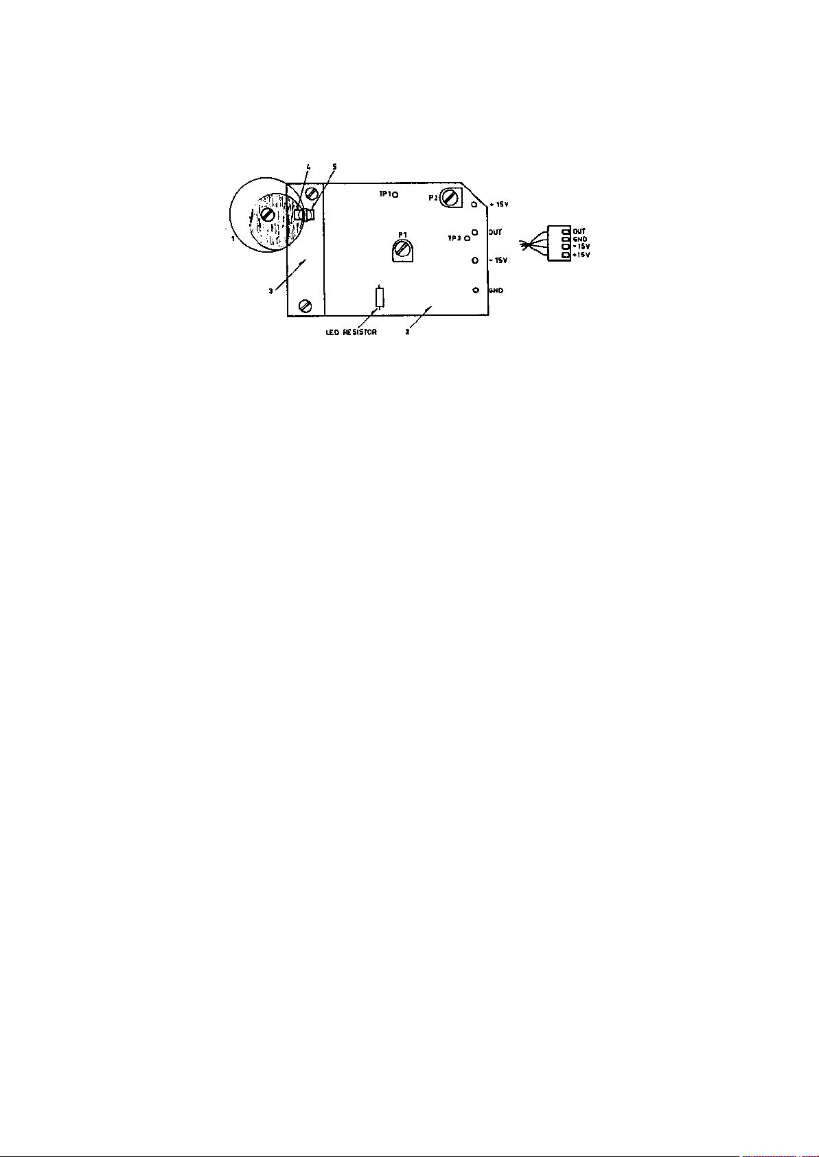
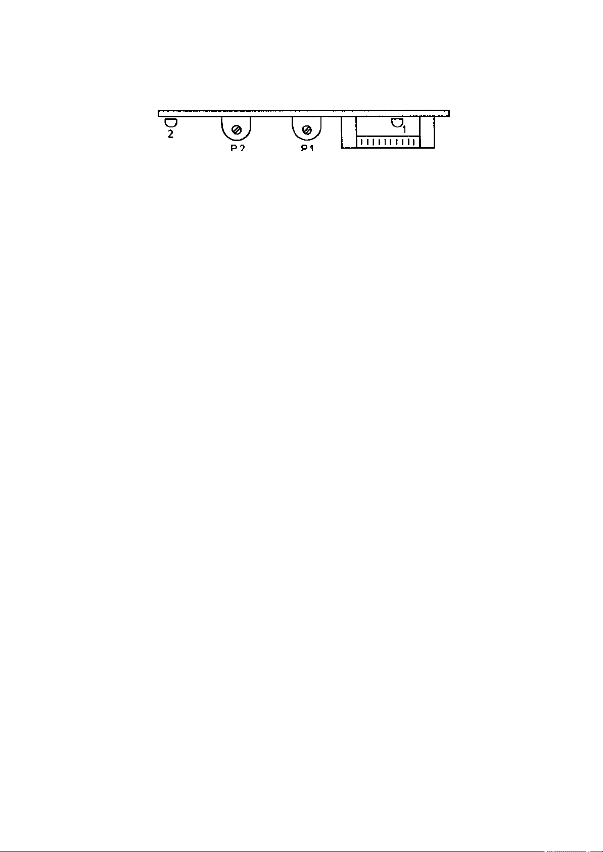
7.11 TAPE TENSION SERVO SENSOR DRAWING 1060
PCB 83-07X
PCB 83-08X
1 - 816552 Excentric diaphragm disc mounted on tension arm.
2 - 410041 PCB 83-07X with infrared LED and
3 - PCB 83-08X with:
4 - 915421 Infrared servo detector.
5 - 915421 Infrared reference detector.
The servo sensor translates the movements of the tape tension
servo arm into a voltage by detecting the amount of infrared light
passing the diaphragm which is moving with the servo arm. The
intensity from the LED light source is kept independent of
variations in temperature by controlling it from an additional
sensor not being covered by the diaphragm.
In both supply and take-up side, movement of the tension arm away
from rest position, corresponds to a decrease in output voltage,
therefore this movement should bring a more transparent part of
the disc between the LED and the servo detector.
7.11.1 ADJUSTMENTS - SUPPLY SIDE
Turn mains power off and open the audio compartment and pull out
the front drawer until it locks.
Put the machine into the upright position and locate the supply
"SERVO OPTO AMPLIFIER.
Turn mains power ON and push the EDIT button once.
Connect a digital voltmeter to 0 volt (black wire) and testpoint
TP2 (brown/black wire).
Set potentiometers P1 and P2 to midposition.
Loosen the center screw and turn the excentric diaphragm until the
major part of it is turning downward and the voltmeter reads
approx. -13 volt.
Turn the diaphragm CCW (counter clockwise) until the voltmeter
reads maximum positive voltage (typically 1 to 10 volts). Now turn
back a little CW (clockwise) until the voltage drops approx. 2
volts (typical reading is approx. 3 volts).
Tighten the center screw while maintaining the meter reading.
WARNING
IT IS VERY IMPORTANT THAT THE DIAPHRAGM
Page 23

DOES NOT TOUCH ANY PART OF THE SENSOR ASSEMBLY
ANY ADDED FRICTION WILL WILL AFFECT THE SERVO SYSTEM
Adjust P1, OFFSET, and P2, GAIN, to get +10 V with arm in rest
position and -10 V with arm in fully drawn position.
The adjustment has to be done several times until the reading is
exactly as indicated.
Remove the protective cover over the supply servo arm. Attach a
spring balance (0-100 g). Measure the servo arm spring tension in
rest and drawn position. If necessary adjust the spring associated
to the servo system below the tape deck.
After adjustment, lock the center screw with Lock-Tite or nail
polish.
+==============================-=================================+
| SERVO ARM IN REST POSITION: | 2 - 5 g ON 0.15" MACHINES |
| | 18 - 22 g ON 1/4" MACHINES |
| | 25 - 30 g ON 1/2" MACHINES |
|==============================+=================================|
| SERVO ARM IN DRAWN POSITION: | 45 - 50 g ON 0.15" MACHINES |
| | 37 - 43 g ON 1/4" MACHINES |
| | 45 - 55 g ON 1/2" MACHINES |
+==============================-=================================+
7.11.2 ADJUSTMENTS - TAKE UP SIDE
Locate the take up "SERVO OPTO AMPLIFIER.
Connect a digital voltmeter to 0 volt (black wire) and testpoint
TP2 (red/black wire).
Set potentiometers P1 and P2 to midposition.
Loosen the center screw and turn the excentric diaphragm until the
major part of it is turning downward and the voltmeter reads
approx. -13 volt.
Turn the diaphragm CW (clockwise) until the voltmeter reads
maximum positive voltage (typically 1 to 10 volts). Now turn back
a little CCW (counter clockwise) until the voltage drops approx. 2
volts (typical reading is approx. 3 volts).
Tighten the center screw while maintaining the meter reading.
WARNING
IT IS VERY IMPORTANT THAT THE DIAPHRAGM
DOES NOT TOUCH ANY PART OF THE SENSOR ASSEMBLY
ANY ADDED FRICTION WILL WILL AFFECT THE SERVO SYSTEM
Adjust P1, OFFSET, and P2, GAIN, to get +10 V with arm in rest
position and -10 V with arm in fully drawn position.
The adjustment has to be done several times until the reading is
exactly as indicated.
Remove the protective cover over the take up servo arm. Attach a
spring balance (0-100 g). Measure the servo arm spring tension in
rest and drawn position. If necessary adjust the spring associated
Page 24

to the servo system below the tape deck.
After adjustment, lock the center screw with Lock-Tite or nail
polish.
Tilt the machine back to its normal position. Keep the drawer open
and locate the "SERVO LIMIT DETECTOR".
Turn P1 fully CCW, then slowly CW until LED 1 lights fully up,
then 1/8 turn more CW.
To check adjustment, press in ONE of the two servo arms about 3 mm
while observing that LED 1 goes OFF. If not, re-adjust P1.
Press the STOP button once. Turn P2 fully CCW.
While pressing BOTH servo arms 2/3 (this has to be done very
accurately) of the way in slowly adjust P2 CW until LED 2 lights
up.
Load tape and check the tape load and tape end funtions by;
a/ Slowly stretch the tape until the servo arms are 2/3 of the way
in. Check that LED 1 goes off and LED 2 goes on.
b/ Wind the tape until it runs out. At tape end check that LED 1
goes off and that the reel motors are turned off.
Check that the output is 0 V when the tension arm is in centre
position or slightly towards restposition. If not, repeat the
adjustment procedure at another position with the disc turned a
few degrees.
NOTE: It is of vital importance that the servo sensor is adjusted
correctly. The output from supply and take-up sensor must be
equal to avoid creeping effects in stop mode. Mis-adjustment
will not only affect tape tension, but also tape end stop
and other functions.
Page 25
7.12 SERVO LIMIT DETECTOR Print 81-01X
Diagram 9737
7.12.1 P1, TAPE END STOP ADJUSTMENT.
Tape end sensing comes from measuring the added output from supply
and take up servo sensors.
The correct point for triggering the tape end stop is approx. 1 mm
before the last servo arm reaches its rest position.
If any adjustments have been done to the servo sensing opto
system, also the tape end sensor might need to be readjusted.
Adjustment is done in EDIT-WIND mode and speed set to stand still.
With one hand on the edge of each reel, turn both reels slightly
to decrease tape tension. Adjust P1 so that tape tension
disappears when the last servo arm is approx. 1 mm from its rest
position.
7.12.2 P2, TAPE LOAD ADJUSTMENT.
With tape in STOP mode without tape tension, manually stretch the
tape so that both servo arms leave their rest positions and adjust
P2 so that tape tension is activated and pinch roller goes to
stand-by position.
Remember to have DIL-switch no. 2 in ON position for this ad justment.
LED INDICATORS.
LED 1: Tape end stop indicator
LED 2: Pinch roller offset indicator.
7.12.3 ELAPSED TIME COUNTER
The elapsed time counter also found on the servo limit detector
pcb. The counter has a full scale deflection of 10.000 hours.
The elapsed time counter is an electro chemical device with a
small dot moving from left to right. Full scale deflection is
factory set to 10.000 hours. When the time indicator dot reaches
its end, the whole indicator can be taken out, turned around and
remounted.
NOTE: If the indicator dot is allowed to disappear into the right
end, the counter is ruined and has to be replaced.
The elapsed timecounter is active in PLAY and RECORD, and in WIND
mode when the tape touches the playback head.
The full scale deflection is set by R34. If other time intervals
are required, the value of R34 can be changed.
Page 26

7.? REEL MOTOR CONTROL AMPLIFIER Print 79-06X
Diagram 9597
Two identical reel motor control amplifiers feed the supply and
take-up motors with power. The two amplifiers are identical and
can be interchanged with each other. They are located on the rear
panel.
The amplifier is of a push-pull type and can supply max. 5 A
output. The output is linear to the voltage at the control input.
I.e. 1 V input corresponds to 1 A output etc. except at high
positive input (over approx. 3V), where the gain will increase.
The amplifier has two adjustment trimmers, both located at the
connector edge. To get access for service, open the drawer
containing the tape deck logic and unfold the hinged audio
amplifiers.
Note that supply and take-up amplifier are mounted 180 degrees in
relation to each other.
To completely remove the reel motor control amplifier, loosen the
two screws on the back panel, which holds the heat-sink. Pull the
heat-sink out together with the amplifier print.
7.?.1 ADJUSTMENTS
P1: DC-OFFSET.
P1 is factory set to leave the motor in stop when tape is not
loaded. A quick control of the DC-offset can be done by pressing
the illuminated speed selector button (this will release the
parking brake). If any of the motors now show any tendency to
move, P1 needs adjustment.
Disconnect the motor connector. Measure the voltage over pins 16
and 17, and adjust P1 for a reading as close as possible to 0 V.
P2: POWER SWITCHING.
To avoid excessive heat being produced in the power supply, the
reel motor control amplifier operates on either high or low
voltage.
In the amplifier, a sensing circuit (T9 - T12) sends a command to
the power supply to order the high voltage when needed. When the
high voltage is switched on, the LED's on the power terminal board
are illuminated.
For operating situations like stand-by, play and record, the low
voltage is used.
During dynamic braking, accelerating and fast winding the high
voltage is switched on.
Page 27
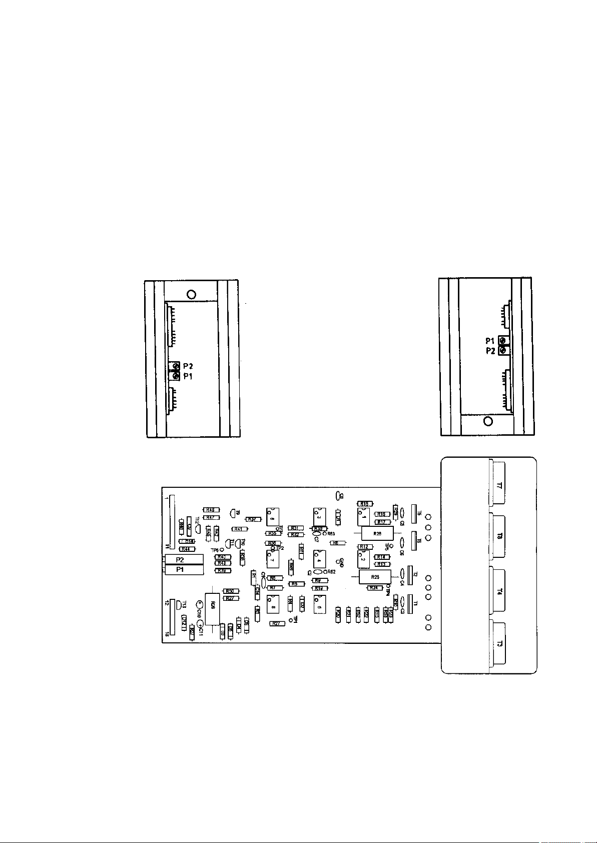
ADJUSTMENT TAKE-UP SIDE
Load the recorder with a full reel on the take-up side. With the
recorder in play mode at the high speed, observe the right LED.
Adjust P2 so that the LED is just about to light up. Check by
manually braking the supply reel very slightly. This should cause
the LED to light up.
ADJUSTMENT SUPPLY SIDE
Load the recorder with a full reel on the supply side. With the
recorder in play mode at the high speed, observe the left LED.
Adjust P2 so that the LED is just about to light up. Check by
manually braking the supply reel very slightly. This should cause
the LED to light up.
Page 28
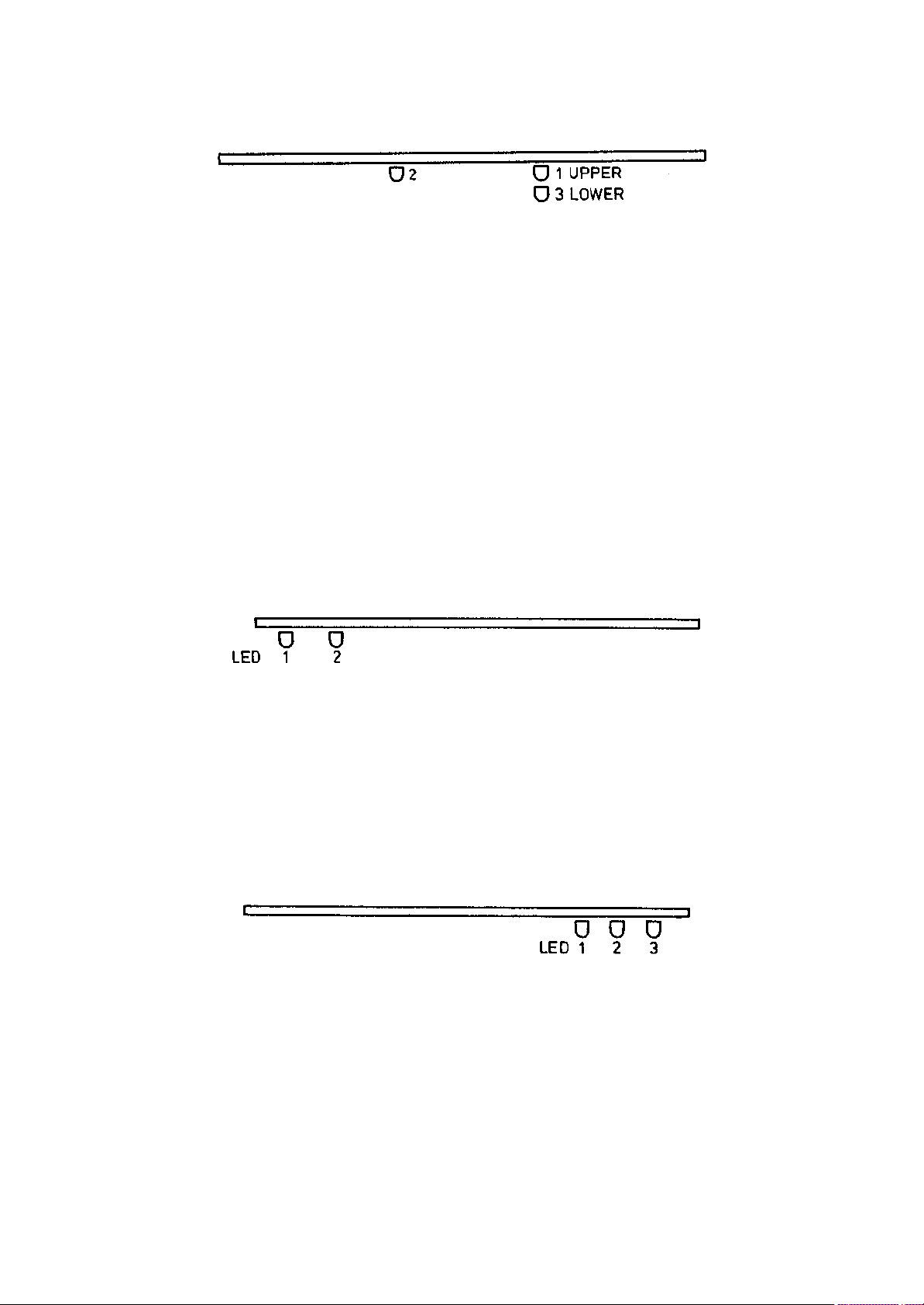
7.? SERVO MIX AMPLIFIER Print 80-163
Diagram 9674
LED's illuminated in different modes
+-----------------------------------------------------------------+
|MODE | LED NO. | REMARKS |
|-------------------------+-----------+---------------------------|
|NO LOAD | 1 | 2 | 3 | Tape tension not activated|
|EDIT | 1 | 2 | 3 | Tape tension not activated|
|STOP LOAD | 1 | | | Tape tension activated |
|DUMP MODE (EDIT + START) | | | 3 | Take-up motor passive |
|START | | | | Nominal speed |
|RECORD | | | | Nominal speed |
|WIND/REWIND | | | | Full wind speed |
|EDIT WIND | | | | Variable wind speed |
|ANTI DUMPMODE | | 2 | | Supply motor passive |
|ANTI DUMPMODE + DUMPMODE | | 2 | 3 | Both reel motors passive |
+-----------------------------------------------------------------+
7.? EDIT AND START ENABLE Print 80-10X
Diagram 9665
LED INDICATORS
LED 1: Pinch roller attack (Start - Record)
LED 2: Mechanical brakes in released position.
7.? REEL MOTOR COMMANDER Print 80-08X
Diagram 9666
LED INDICATORS
LED 1: Rewind command or brake command for supply motor.
LED 2: Wind command or brake command for take up motor.
LED 3: Tape action (Play - Rec - Wind - Dynamic brake).
Page 29
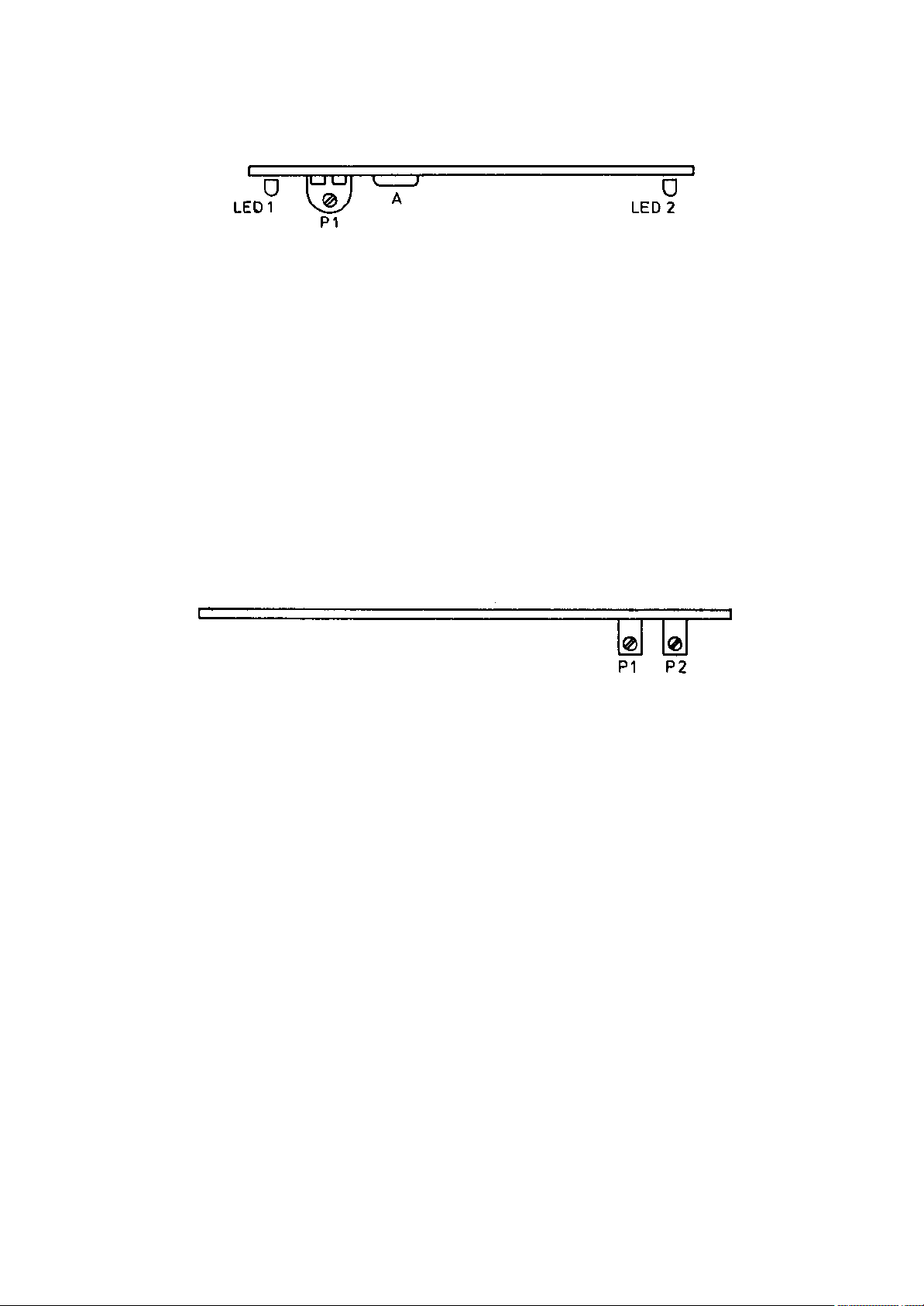
7.? TAPE MOTION SENSOR Print 80-17X
Diagram 9900
7.?.1 TAPE LIFT SPEED SETTING
P1: Speed sensor for tape lift in wind mode, adjusted to
activate tape lifter at double high speed, i.e. approx. 60
ips.
LED INDICATORS
LED 1: LED for tape lift activity.
LED 2: LED for tape load (active stand-by).
A: Test point for tacho input pulses.
7.? CAPSTAN SPEED DETECTOR Print 80-17X
Diagram 9675
NOMINAL SPEED ADJUSTMENT
P1 : High speed adjustment.
P2 : Low speed adjustment.
Nominal tape speed is set by holding down the illuminated speed
selector and adjust for correct reading in ips in the display.
Page 30
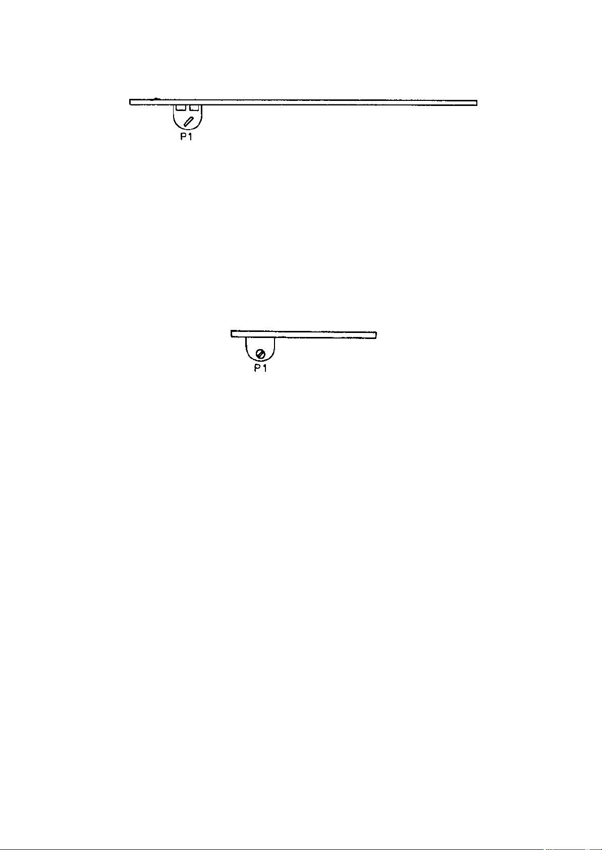
7.? CAPSTAN DRIVER AMPLIFIER Print 80-18X
Diagram 9676
P1: Servo loop gain, adjusted for minimum wow and flutter at low
tape speed.
7.? CAPSTAN OUTPUT AMPLIFIER Print 80-19X
Diagram 9759
start ramp ?
ramp attack ?
7.? HEADPHONE AND SPEAKER AMPLIFIER Print 82-17X
Diagram 9953
The headphone output is driven by two identical monitor
amplifiers. With potentiometer P1, the level can be adjusted to
suIt the sensitivity of the headphones.
With the front panel volume control....
Page 31
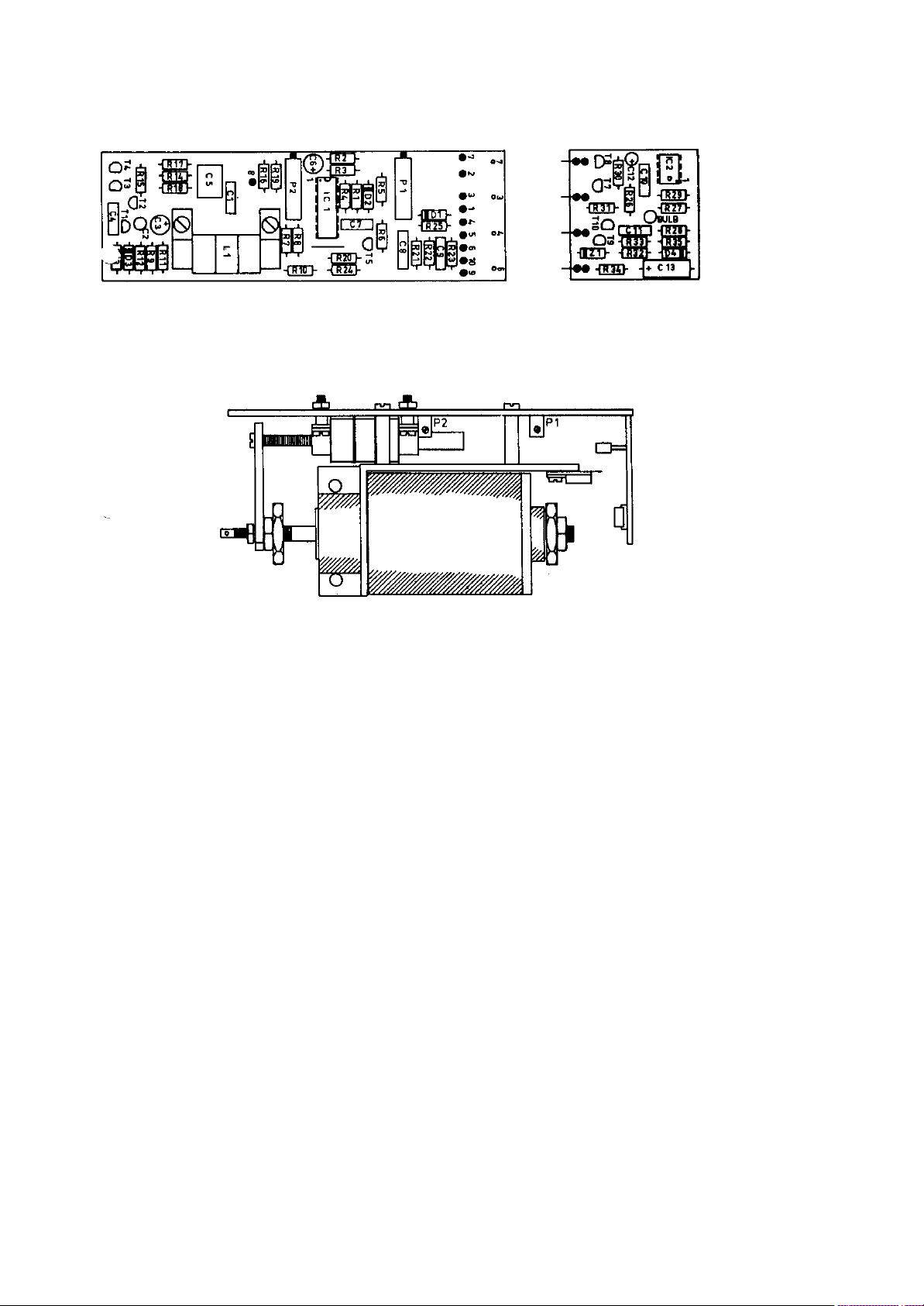
7.? PINCHROLLER DRIVER Print 81-16X
81-18X
Diagram 9789
7.?.1 THEORY OF OPERATION
The eletronically controlled pinchroller solenoid is equipped with
a position sensor in the form of a differential transformer L1.
The ferrite core of the transformer is mechanically connected to
the solenoid shaft.
A wien bridge generator supplies 225 kHz 8 Vpp to the transformer
system. The output from the transformer is routed through a buffer
stage (T1), and is then rectified (D3). The second buffer (T4)
supplies a DC voltage that is proportional to the position of the
solenoid shaft. The voltage at the emitter of T4 is approx. 10 V
in the rest position and approx. 14 V in top position.
IC1 (8.9.10.) compares the position information with the charge
condition of C6.
When 24 V is applied to the ATTACK input, IC1 (12.13.14) will
charge C6 through R5. If the voltage on C6 is higher than the
position information, the comparator will switch on transistor T5
and T6 in order to move the solenoid shaft to the corresponding
position. The speed of the movement is set by the resistor R5.
When 24 V is applied to the OFFSET input, the signal is attenuated
through potentiometer P1 and C6 will be charged to a level
corresponding to the setting of P1. This is used to create the
active stand-by position, where the pinchroller is parked very
close to the capstan shaft, and very fast starting times can be
achieved.
The capstan command output will activate the capstan motor when
the pinch roller has reached correct position. The pinchroller
position is constantly sensed and the capstan command point is
Page 32
adjusted with P2.
The wien bridge generator is mounted on the pinchroller driver
print. The generator supplies 225 kHz 8 Vpp and this signal is
routed to all three solenoid drivers.
The enable output is a circuit that secures that the output stages
to the solenoid coils are inoperative during power on and off
sequences.
Capacitor C13 is charged through R32 when power is switched on. In
approx. 3 seconds the base of T9 will rise to 1,2 V and activate
T10 to drain the enable output.
At power off, the 24 V will start to drop and after a few volts
start discharging C13 through D4 and R 35 and quickly cut off T9
and T10.
7.?.2 PINCHROLLER DRIVER ADJUSTMENTS
P1, OFFSET
The stand-by position of the pinch roller is adjusted with the
offset potentiometer P1.
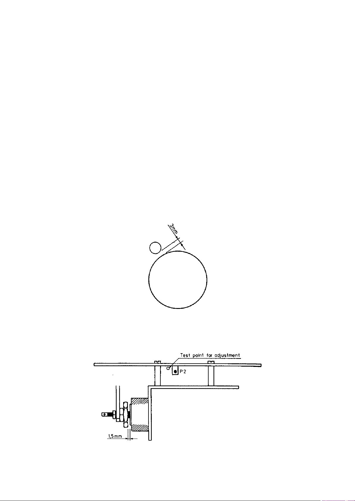
With the recorder in STOP mode, i.e. with tape tension, adjust P1
so that the pinchroller stays 3 mm from the capstan shaft.
P2, CAPSTAN COMMAND
The moment that the capstan motor is started is adjusted with the
capstan command potentiometer P2.
Page 33

Insert a 1,5 mm plate in the travel path of the pinch roller
solenoid shaft. Connect a DC voltmeter to the capstan command
output. This point is easiest found at the end of resistor R19,
located next to P2.
Press START to activate the solenoid, which will now travel to its
end position less 1,5 mm. Adjust P2 for reading of +20 V on the
voltmeter.
NOTE: Make sure that stand-by position and capstan command
position are not too close to each other and that NO
OVERLAPPING OCCUR. If this happens it will be impossible to
enter WIND mode from START and activate stand-by.
7.? TAPE LIFT DRIVER Print 81-15X
Diagram 9788
The two tape lift drivers that lifts the tape from the
erase/record and the playback head are in design closely related
to the pinch roller driver.
There are however some differences.
- The tape lift drivers are mounted 180 degrees in relation to the
pinch roller driver.
- The tape lift drivers are not equipped with a HF generator. The
HF generator mounted on the pinch roller driver feeds all three
solenoid drivers.
- A different set of trimmers are used for the tape lift
adjustments.
THEORY OF OPERATION
The electronically controlled tape lifter solenoid is equipped
with a position sensor in the form of a differential transformer,
L1. The ferrite core of the transformer is mechanically connected
to the solenoid shaft.
HF (225 kHz, 8 Vpp) is routed from the generator mounted on the
pinch roller driver to the HF input.
The HF is amplified in IC 1 (5.6.7) and injected to the primary
coil of L1. The output from the transformer is routed through a
buffer stage (T1) and is then rectified (D3) and filtered (C4).
The second buffer (T4) supplies a DC voltage that is proportional
to the position of the solenoid shaft. The voltage at the emitter
of T4 is approx. 10 V in rest position and approx. 14 V in top
position.
IC1 (8.9.10) compares the position information with the charge
condition of C6.
When 24V is applied to the ATTACK input, IC1 (12.13.14), the
signal is first attenuated through potentiometer P1 and C6 will be
charged to a level corresponding to the setting of P1.
If the voltage on C6 is higher than the position information, the
comparator will switch on transistors T5 and T6 in order to move
the solenoid shaft to the corresponding position. The speed of the
movement is set by potentiometer P4.
Page 34
The enable circuit is controlled from the pinch roller driver and
ensures that the output stages to the solenoid coils are
inoperative during power on and off sequences.
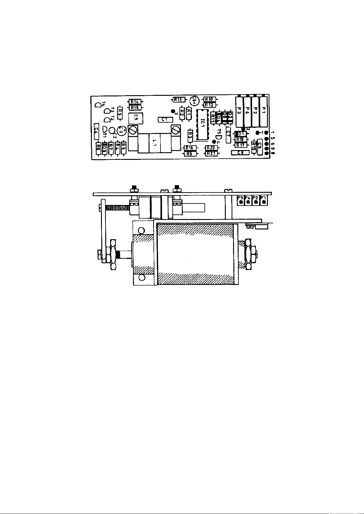
7. ADJUSTMENTS
The tape lift driver has four adjustment points.
P1, MAX TRAVEL
With P1 the lifting height is adjusted.
Do not adjust to max. tape lift as this will affect the response
of the release speed. Max. setting is 1 mm from top position.
P2, OFFSET.
This adjustment is intended for future features. The potentiometer
is normally not mounted.
P3, RELEASE
With P3 the release speed can be adjusted for a smooth and silent
operation. On the playhead lifter P3 is factory set and the
potentiometer normally replaced by a 10 kohm resistor.
On the erase/record head lifter P3 is set so that it corresponds
with the attack speed of the playhead lifter.
P4, ATTACK
With P4 the attack speed can be adjusted for a smooth and silent
Page 35
operation. On the playhead lifter P4 is factory set and the
potentiometer normally replaced by a 10 kohm resistor.
On the erase/record head lifter P4 is set so that it corresponds
with the release speed of the playhead lifter.
7. COUNTER OPTO AMPLIFIER Print 79-083
Diagram 9599
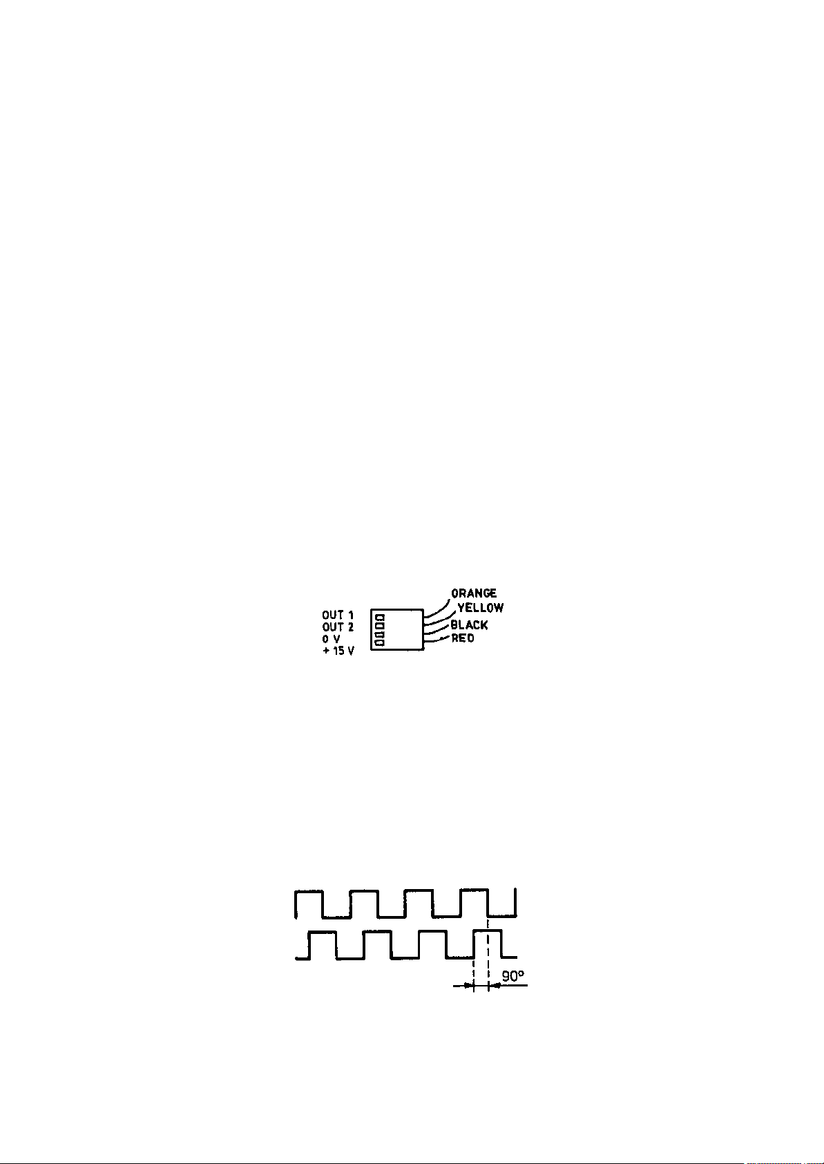
ADJUSTMENTS
Check that the counter tacho disc is in good condition and that
the edge is not worn.
Connect a double beam oscilloscope to the output test point (found
as two soldering tags on the solder side of the prints.)
Each output shall have a mark/space ratio of 1:1 +/- 10%. This is
factory-adjusted by selecting values for R3 and R11.
The two outputs must be offset by 90 degrees. This is adjusted by
loosening the two screws that holds the print to the tape deck and
moving the print very little. While moving the print (in play mode
at 15 ips) watch the offset on the oscilloscope.
Depending on which phase comes first, the counter will count
correct or reversed.
If a position is found where the counter works properly but
counting in reverse direction, the yellow and orange wires should
change position. The wires can be taken out of the connector
without soldering.
When phase has been adjusted to 90 degrees offset, go to WIND mode
and check that offset is still 90 degrees. If not, readjust at
play speed.
Make sure the protective cover over the tacho disc is mounted so
that the ribbon cables from the terminal print do not touch the
disc when the recorder is closed.
NOTE: The mechanical distance between the two photo interruptors
has an influence on the phase offset. When a photo
interruptor has been replaced it might be necessary to
press them more together or separate them slightly with a
screwdriver.
CORRECT OFFSET
Page 36

7.25 REEL MOTOR BRAKE ADJUSTMENT
The mechanical brakes are only active in UNLOAD mode (tape tension
off) and as emergency brake at power failure.
1.
Disconnect the reelmotor from its related Reel Motor Control
Amplifier.
2.
On the reelplatform, unscrew the centre hex screw completely. By
hand disengage the brake solenoid and slowly raise and remove the
complete reelplatform.
3.
Unscrew the four hex screws securing the reelmotor assembly to the
tape deck. By hand support the motor from below to prevent it from
falling down.
4.
Remove the reel motor assembly (c) from the tape deck.
5.
By loosening the two scews (a) securing the solenoid assembly (b)
to the reel motor assembly (c), the brake band can now be
adjusted. Adjustment is done by moving the solenoid assembly (b)
away from or towards the brake drum (e).
6.
Manually engage and hold the solenoid. Move the solenoid assembly
(b) towards the brake drum housing just until the brake band
touches the inner walls (f). Now tighten the two screws (a).
7.
While solenoid is engaged, re install the reel platform. Release
the solenoid and check operation of brake by turning the reel
platform. Note that the brake effect is selective to the rotation
direction.
8. Re install the reel motor assembly and connect the Reel Motor
Control Amplifier.
Drawing # ????
Page 37

L Y R E C S E R I E S T R 5 5
+++++++++++++++++++++++++++++++++
S P A R E P A R T S
+++++++++++++++++++++
PART NO PART DESCRIPTION
-----------------------------------------------------------------
VU-METER PANEL
++++++++++++++
960701 VU-meter AL 22 F
961731 VU-meter lamp, 24 V, 1,2 W
915111 LED, record indication, NSL-5026
903164 10K Lin, potentiometer, varispeed
903167 22K Log, potentiometer, level
TAPE DECK
+++++++++
410031 Pinchroller 1/4"
501031 Pinchroller 1/2"
880411 Top cover for pinchroller
896001 Base plate for tape tension arm, supply
896002 Base plate for tape tension arm, take-up
896011 Cover for tape tension arm, supply 1/4"
899151 Cover for tape tension arm, supply 1/2"
896012 Cover for tape tension arm, take-up 1/4"
899152 Cover for tape tension arm, take-up 1/2"
960101 Brake solenoid
926201 Reel motor
894911 Brakedrum
970611 Spring washer
895921 Brakeband
896891 Brake spring
501121 Capstan motor cpl with strobodisc and preamp
877761 Pullspring for pinchroller
501032 Returnspring for pinchroller
897851 Tape lifter return spring
410036 Solenoid 40 mm, without driver pcb
501033 Tape tension servo arm, supply 1/4"
501035 Tape tension servo arm, supply 1/2"
501034 Tape tension servo arm, take-up 1/4"
501036 Tape tension servo arm, take-up 1/2"
Page 38

501037 Tape tension servo spring
816552 Excentric servo disc
810592 Tape guide roller .15"
892281 Tape guide roller 1/4"
899161 Tape guide roller 1/2"
892451 Top cover for tape guide roller 1/4"
899171 Top cover for tape guide roller 1/2"
892442 Base plate for tape guide roller, supply
892441 Base plate for tape guide roller, take-up
899262 Tape timer strobo disc 64:1
897732 Sidepanel supply side
897731 Sidepanel, take-up side
410022 NAB reel adaptor complete 0.15" (QC)
501122 NAB reel adaptor complete 1/4"-1/2"
887631 NAB adaptor positioning spring
880261 NAB adaptor pressure spring
410024 DIN reel adaptor complete with 300 mm plate
893521 DIN adaptor pressure spring
410023 CINE reel adaptor complete
898871 CINE adaptor pressure spring
501040 Tape cutter blade, fixed
501041 Tape cutter blade, moving
896921 Spring for tape cutter
897561 Return spring for tape cutter
897521 Edit wind speed lever
TAPE DECK ELECTRONIC PARTS
++++++++++++++++++++++++++
410026 Capstan pre-amplifier PCB 83-141
410041 Servo opto amplifier PCB 83-073
410046 Counter opto amplifier PCB 79-083
410050 Tape deck terminal print PCB 79-173
410037 Pinchroller solenoid driver PCB 81-181/161
410038 Tape lift solenoid driver PCB 81-153
411020 Tape timer display PCB 78-001
411030 Motherboard 1/4"-1/2" PCB 80-063
411501 Tacho logic PCB 80-001
411502 Push button amplifier PCB 78-011
411503 Diode matrix PCB 80-075
411504 Edit and start enable PCB 80-102
411505 Reel motor commander PCB 80-081
411506 Tape motion sensor PCB 80-096
Page 39

411507 Capstan start time sensor PCB 80-203
411508 Edit wind logic PCB 80-115
411509 Servo limit detector PCB 81-012
411510 Tape lift and cut logic PCB 80-142
411511 Tape end motor brake PCB 80-151
411512 Servo mix amplifier PCB 80-163
411513 Capstan speed detector PCB 80-172
411514 Capstan driver amplifier PCB 80-182
411515 Capstan output amplifier PCB 80-193
411516 Monitor amplifier stereo PCB 82-170
410530 PSU regulator module PCB 79-183
410021 Reel motor control PCB 79-063
410540 PSU terminal print PCB 79-193
410510 Mains transformer assy complete
HEADS
+++++
MONO FULL TRACK:
924203 Erase head full track
924204 Record head fulltrack
924205 Playback head full track
STEREO, 0,75 MM SEPARATION:
924203 Erase head full track
924202 Record head stereo
924201 Playback head stereo
2-TRACK, 2 mm SEPARATION:
924208 Erase head 2-track
924206 Record head 2-track
924207 Playback head 2-track
STEREO 1/2":
924303 Erase head 2-track 1/2"
924304 Record head 2-track 1/2"
924305 Playback head 2-track 1/2"
HEADBLOCK
+++++++++
501042 Headblock cover plate
501043 Backcover for headblock 1/4"
501044 Backcover for headblock 1/2"
867831 Flutter idler roller
501045 Flutter idler cpl with holder and bearings
897111 Non rotating tape guide 1/4"
897114 Non rotating tape guide 1/2"
874641 Flange for non rotating tape guide
Page 40

501046 Headstack mounting plate 6 mmm
869061 Azimuth adjustment screw
869051 Tilt adjustment ballpoint screw
AUDIO SECTION
+++++++++++++
412501 AM77 audio amplifier PCB without EQ
412502 Record equalizer PCB
412503 Playback equalizer PCB
412510 Bias oscillator PCB 77-001
927111 Record relay A2625
923102 Line input transformer TD 4016
923122 Line output transformer TD 4012
GENERAL COMPONENTS
++++++++++++++++++
905311 10.000 uF, 40 V Smoothing capacitor
911101 1N4148 Diode
911231 1N5401 Diode
911391 1N821 Diode, zener
911201 PK05F Rectifier bridge
911202 26MB10A Rectifier bridge
912101 BC184 Transistor
912111 BC214 Transistor
912113 2N4403 Transistor
912121 2N2369 Transistor, switch
912203 TIP42A Transistor
912205 TIP120 Transistor
912207 TIP125 Transistor
912211 TIP145 Transistor
912221 TIP641 Transistor
912401 2N1711/BC140 Transistor
912411 2N2905/BC160 Transistor
912421 MJ2955 Transistor
912431 2N3055 Transistor
912511 PN4393/2N4393 Transistor, field effect
912611 TAG 201-400 Triac
913101 TL081 IC opamp
913102 TL071 IC opamp
913103 TL091 IC opamp
913107 TL072 IC opamp
Page 41

913111 TL084 IC opamp
913116 TBA231 IC opamp
913121 LM301AN IC
913125 LM311 IC
913128 LM318 IC
913141 LM386-N4 IC
913171 ULN2803/L603 IC
913175 UDN2981 IC
913201 LM340 K5/LM309 IC, voltage regulator
913213 LM320LZ-12/uA79M12 IC, voltage regulator
913215 LM320 K15 IC, voltage regulator
913225 LM340 K15 IC, voltage regulator
913233 LM350 IC, voltage regulator
913911 AD7530JN IC, CMOS
914406 4013 IC, CMOS
914416 4040 IC, CMOS
914426 4093 IC, CMOS
914436 4098 IC, CMOS
914451 4520 IC, CMOS
914711 7437 IC, TTL
914716 7473 IC, TTL
914721 7490 IC, TTL
914726 74121 IC, TTL
914751 74LS132 IC, TTL
914753 74LS138 IC, TTL
501047 8748 IC, Programmed
914811 8255A IC
915101 LED 3 mm, red
915121 LD271 LED, infrared
915302 H21A1 Opto coupler
915421 BP104 Photodiode, infrared
915221 MAN6640 Double numeric display
902311 33E Resistor network, 8 separate
902321 1K5 Resistor network, 8 separate
902331 10K Resistor network, 8 separate
902351 22K Resistor network, 15 common
903102 100E Potentiometer, single turn VA05V
903104 220E Potentiometer, single turn VA05V
903111 4K7 Potentiometer, single turn VA05V
903113 10K Potentiometer, single turn VA05V
903115 22K Potentiometer, single turn VA05V
903117 47K Potentiometer, single turn VA05V
Page 42

903118 100K Potentiometer, single turn VA05V
903123 1M Potentiometer, single turn VA05V
913143 10K Potentiometer, single turn VA05H
903147 47K Potentiometer, single turn VA05H
903207 1K Potentiometer, multiturn
903211 5K Potentiometer, multiturn
903213 10K Potentiometer, multiturn
903215 22K Potentiometer, multiturn
907120 Coil 4.7 mH
898601 Adjustable coil S14, 2.5 mH
898621 Adjustable coil S14, 8 mH
898641 Adjustable coil S14, 13 mH
898581 Ferrite transformer T18 0008 T2, bias
898591 Ferrite transformer T18 0017 T1A, erase
501048 Differential transformer
921111 DIL switch, 8 pole
921125 Toggle switch TT21. 2-pole
921231 Mains switch, 1852.1102
921255 Toggle switch 7201
922211 Pushbutton EAO 01-121
922221 Top cover with engraved legend, white
922222 Top cover with engraved legend, red
927111 A2625, relay
927114 A2420, relay
960301 Elapsed time counter module
961701 Lamp for pushbutton, 36 V, 50 mA
962010 2.000 MHz crystal
962041 6.000 MHz crystal
923205 Mains transformer DK5533B (2 x 12 V)
923206 Mains transformer DK5534 (5, 24, 2 x 15 V)
969047 Service manual TR55 1/4 and 1/2"
969054 Service manual TR55-QC
Page 43

10. APPLICATION NOTE
10.1 AUTOMATIC SWITCHING TO LINE INPUT IN STOP MODE.
The AM77 audio amplifier used in the TR55 series of recorders is
hardwired to playback.
With a simple modification it is possible to have automatic
switching to LINE INPUT whenever the machine is not running or
REPRO manually selected.
The modification requires two zenerdiodes ZF 6,2 V and ZF 4,7 V
and one diode 1N4148 in each amplifier.
Locate diode D30 and replace it with zenerdiode 6,2 V.
Locate diode D32 and replace it with zenerdiode 4,7 V.
Install a new diode between the LINE command input (edge connector
no A11) and the junction of R87/R79/D24. See enclosed extract of
diagram 1039/9171.
11
February 1990.
SERVICE BULLETIN
VALID FOR: Lyrec TR55, 1/4" and 1/2" with bias oscillator
pcb 77001, with 187.5 kHz bias frequency (6 MHz
crystal).
Serial nos 8810305 to 8910507.
SYMPTOM: Bias oscillator do not start up properly or starts
with wrong frequency at power on.
CAUSE: Missing capacitors on oscillator pcb.
REMEDY: Remove oscillator pcb and inspect soldering side.
Two ceramic capacitors should be mounted. If not,
install 47 pF and 18 pF as shown.
ooOoo
Page 44

February 1990.
SERVICE BULLETIN
VALID FOR: Lyrec TR55, 1/4", 1/2" and QC.
Serial nos 8910405 to 8910706.
SYMPTOM: Difficulty to enter "Edit wind mode".
CAUSE: Incorrect mounting of 2 components.
REMEDY: Open front drawer containing the tape deck logic
and locate the pcb "Edit wind logic" (pcb 80115)
at motherboard connector J9.
Locate and swop position of resistor R5 (4k7) and
diode D7 (1N4148). Se drawing 9669 for exact
location and polarisaton of diode.
ooOoo
Page 45

1990 12 16
MODIFICATION OF THE TR55 POWER SUPPLY (all versions)
Purpose: To reduce the risk of crosstalk generated in the
headphone/speaker amplifier.
Mod. Kit contains:
25 cm. of twisted cable with 1 AMP connector.
70 cm. of twisted cable with 2 AMP connectors.
75 cm. of twisted cable with 1 AMP connector.
4 pcs. of nylon straps and 2 selfaddesive tiepoints.
Mod. procedure:
1. Turn off the power, disconnect the power line.
2. Remove the psu. from the machine by:
a: Remove the grid on top of the psu.
b: Remove the psu. by loosen and remove the four 4mm. screws securing
it.
c: Loosen and remove the two 3mm. screws securing the "Remote display
and Remote control" connector plate.
d: Gently withdraw the psu about 10 cm.
e: Disconnect the 40 pole ribbon cable connector from the psu.
Furthermore disconnect the two cables comming from the two reel
motors connected to the reel motor control amplifiers.
f: Now fully remove the psu.
3. From the rear side of the psu locate the three heatsinks in the
middle.
4. Remove the three coverplates by pushing them upwards. Locate and
unscrew the four 3mm. screws securing the heatsink assembly to the
psu. panel.
5. Locate and unscrew the four 4mm. screws securing the transformer
assembly to the psu. panel.
6 Now gently "open" the psu. by withdrawing the heatsink and the
transformer assembly from the psu. panel.
7. Route the 25cm. cable from the right side of the psu. terminal
pcb. containing the 40 pole connector in parallel with the
exsisting wiring harness to the pcb. located at the rear side of
the heatsink.
8. Solder the new brown wire to the printet circuit at the point
where the browm wire is connected.
9. Solder the new black wire to the printed circuit at the point
where all the other black wires are connected.
10.Using two nylon straps tie the new cable to the exsisting wiring
harness.
11.While paying attention not to damage any cables reassembly the
power supply unit.
12.Open the front drawer of the machine using a 3mm. Allen Hex key
and lower the Audio compartment. Now tilt the machine by loosen
and remove rear bolts securing it to the console (machine stand).
Page 46

13.At the rear side of the mother board -pcb. 83051 - locate the two
twisted wires connected between J25 pin 3/4 and 5/6 to J29 pin 8
and 5/6. Unsolder, remove and discard these two wires.
- They are typically white and blue.
14.Solder the new 75cm. cable at J29, the brown wire at bin 8 and the
black wire at bin 5/6.
15.Using the two selfaddeshive tiepoints route the new cable from J29
to the edge of the motherboard next to J25.
16.Reinsert the psu. in the machine remembering to reconnect the two
reel motor cables and the 40 pole ribbon cable connector. Mount
the grid on the psu.
17.Remount the "Remote" connector plate.
18.Connect the last new cable - 70cm. - between the new cable
connector in the psu and at the motherboard.
19.Check once more the machine for any loose parts - now close the
front drawer - check the ribbon cables - close the Audio
compartment.
20. The modified machine is now ready for test.
Page 47

TR55 Application note.
Changing excentric servo disk (servo sensor).
1. Check mechanical tension of supply and take up servo springs.
Measure tension with spring balance in vertical position.
TR55-1/4" Rest position 20 g (tape tension 95 g)
Max position 40 g
TR55-1/2" Rest position 30 g (tape tension 110 g)
Max position 50 g
TR55-0.15" Rest position 2 g (tape tension 55 g)
Max position 50 g
2. Connect voltmeter to TP2 (digital voltmeter recommended).
3. Set P1 and P2 in center position.
4. With servo arm in rest position, loosen screw a little and turn the
excentric disk into the optosensor until approx 8 V is reached at TP2
(This should give approx -12 V with arm in top position). Tighten
screw.
5. Adjust offset, P1, so that the same numeric voltage is achieved in rest
and top position (for example + and - 7 volt).
6. Adjust gain, P2, to expand voltage to +10.0 V in rest position and
-10.0 V in top position.
7. Check that, with arm in middle position, or slightly towards rest
position gives 0 V out at TP2.
8. In general, it is more important that supply and take-up side are
adjusted to give identical voltages, rather than absolute values.
Page 48

12. DIAGRAMS
----------------------------------------------------------------- No Title Size
----------------------------------------------------------------- AUDIO:
1991 Cable scheme 2 channel electronics AM77 w VU bridge A3>A4
2002 Record-Playback amplifier AM77 with Dolby HX Pro A1
2003 Dolby HX Pro circuit A3>A4
1040 Component location for AM77 A2
1070 Record equalizer A3>A4
1038 Repro and Sync Equalizer A4
1452 Headstack connections for 1/2" 4-track version S/S A4
2435 Headstack connections for 1/2" 4-track version INT A4
2599 187.5 kHz crystal generator A4
9953 Headphone and speaker amplifier A3>A4
TAPE DECK LOGIC:
9878 Motherboard and connector location A3>A4
9781 Tachometer logic 1/3 A3>A4
9782 Tachometer logic 2/3 A3>A4
9783 Tachometer logic 3/3 A3>A4
9784 Tachometer logic, component layout A3>A4
9716 Tape timer display connections A4
9674 Servo mixer amplifier A3>A4
1085 Servo mixer amplifier, component layout A4
9673 Tape end motorbrake A3>A4
9672 Tape lift and cut logic A3>A4
9737 Servo limit detector A3>A4
9669 Edit wind logic A3>A4
9668 Capstan start time sensor A3>A4
9900 Tape motion sensor A2
9666 Reel motor commander A3>A4
9665 Edit and Start enable A3>A4
9664 Diode matrix A3>A4
9312 Pushbutton amplifier A4
CAPSTAN MOTOR SYSTEM:
1061 Capstan speed preamplifier A4
9675 Capstan speed detector A3>A4
9676 Capstan driver amplifier A3>A4
9759 Capstan output amplifier A3>A4
BELOW TAPE DECK:
1060 Servo opto amplifier A4
9599 Counter opto amplifier A4
9789 Pinch roller driver A3>A4
9788 Tape lifter driver A3>A4
REAR PANEL:
9757 Power supply A2
9597 Reel motor control A2
ACCESSORIES:
9790 VU meter panel A3>A4
9750 Remote control connections A4
Page 49

The following pages contain a listing of all connections in tape
deck electronics motherboard.
Each connector is labelled with a "J" and a number and the mating
printed circuit board or cable is labelled likewise, and for each
pin on each connector, the listing informs which connector(s) and
pin(s) it is connected to.
On the last page, a listing of all connectors is given, including
the name of the connecting part, and the drawing number of the
connecting part.
Drawing 9878 shows the positions of the printed circuit boards and
connectors on the motherboard.
Page 50

CONNECTOR J1: CONNECTING TACHOMETER LOGIC AND MOTHERBORD
PIN # CONNECTS TO: FUNCTION:
1 J12,1 TACHO PULSES OUT
2 J12,2 TACHO PULSES OUT
3 N.C.
4 N.C.
5 N.C
6 N.C.
7 N.C.
8 J3,7-J16,4 SET CUE COMMAND
9 J3,8-J15,4 SET ZERO COMMAND
10 J3,5-J18,4 SEARCH CUE COMMAND
11 J3,6-J17,4 SEARCH ZERO COMMAND
12 J3,12 TACHO PULSES 1
13 J3,13 TACHO PULSES 2
14 J11,2 COUNTER INHIBIT
15 N.C.
16 J13,19-J28,2-J14,42-J33,8 HIGH SPEED LAMP
17 J14,4 SPEED DISPLAY COMMAND
18 J14,3 + AT WIND/REWIND
19 J14,18-J21,6 START LAMP
20 J3,1-J14,26-J22,8 STOP LAMP
21 N.C.
CONNECTOR J2: CONNECTING TACHOMETER LOGIC AND MOTHERBORD
PIN # CONNECTS TO: FUNCTION:
1 J4,1-J4,21 +15 V
2 J4,1-J4,21 +15 V
3 J4,2-J4,22 -15 V
4 J4,2-J4,22 -15 V
5 J4,3-J4,23 +5 V
6 J4,3-J4,23 +5 V
7 J4,3-J4,23 +5 V
8 J4,3-J4,23 +5 V
9 J14,5-J17,3 SEARCH ZERO LAMP OUT
10 J14,6-J18,3 SEARCH CUE LAMP OUT
11 J11,3-J14,25-J22,7 STOP COMMAND OUT
12 J14,19-J21,7 START COMMAND OUT
13 J14,14-J20,7 FORWARD WIND COMMAND OUT
14 J14,10-J19,7 REWIND COMMAND OUT
15 N.C.
16 J9,12 -V REF
17 J9,1 COMPRESSED ANALOGUE SPEED OUT
18 J4,4-J4,24 GROUND
19 J4,4-J4,24 GROUND
20 J4,4-J4,24 GROUND
21 J4,4-J4,24 GROUND
CONNECTOR J3: CONNECTING REMOTE CABLE AND MOTHERBORD
PIN # CONNECTS TO: FUNCTION:
1 J1,20-J14,26-J22,8 STOP COMMAND/LAMP
2 J13,5-J14,20-J21,8 START COMMAND/LAMP
3 J5,12-J11,6-J12,3-J14,15-J20,8 FORWARD WIND COMMAND/LAMP
4 J5,11-J11,5-J12,4-J14,11-J19,8 REWIND COMMAND/LAMP
5 J1,10-J18,4 SEARCH CUE COMMAND
6 J1,11-J17,4 SEARCH ZERO COMMAND
7 J1,8-J16,4 SET CUE COMMAND
8 J1,9-J15,4 SET ZERO COMMAND
9 J13,7 BREAK
10 J3,27 GROUND
11 J10,1 RECORD INHIBIT
12 J1,12 TACHO PULSES 1
13 J1,13 TACHO PULSES 2
14 J5,7-J13,4 PINCHROLLER ATTACK
15 J8,6 PINCHROLLER OFFSET
16 J7,1-J8,4 PLAYLIFT
17 J7,2-J8,5 ERASE LIFT
18 J10,5-J13,9-J14,30-J23,8 RECORD COMMAND/LAMP
19 J14,29-J23,4 RECORD BUTTON DEPRESSED
20 J7,6-J8,8-J9,6-J10,7-J13,10-J14,34-J24,3-DIL4 EDIT COMMAND/LAMP
21 J25,20-J27,8 VARISPEED
22 J27,7 CAPSTAN SYNC
23 J25,13 HARDWARE
24 N.C. +24 V
25 N.C. +15 V
26 N.C. +5 V
27 J3,10 GROUND
28 N.C. -15 V
29 RESERVED
Page 51

30 RESERVED
31 N.C.
32 J5,16 PINCHROLLER PLAY POSISITION
33 J5,1-J3,2 SUPPLY SERVO SENSOR
34 J5,2-J8,3-J26,5 TAKE UP SERVO SENSOR
CONNECTOR J4: CONNECTING POWER CABLE AND MOTHERBORD
PIN # CONNECTS TO: FUNCTION:
1 J2,1-J2,2-J4,21 +15 V FOR TACHOMETER LOGIC
2 J2,3-J2,4-J4,22 -15 V FOR TACHOMETER LOGIC
3 J2,5-J2,6-J2,7-J2,8-J4,23 +5 V FOR TACHOMETER LOGIC
4 J2,18-J2,19-J2,20-J2,21-J4,24 GROUND FOR TACHOMETER LOGIC
5 J4,25 +5 V FOR TAPEDECK AND AUDIO
6 J4,26 +15 V FOR TAPEDECK
7 J4,27-J25,7-J25,17-J29,6-J30,6 GROUND FOR AUDIO
8 J4,28-J25,6-J25,16-J29,8-J30,8 +15 V FOR AUDIO
9 J4,29-J25,5-J25,15-J29,7-J30,7 -15 V FOR AUDIO
10 J4,30 -15 V FOR TAPEDECK
11 J4,31 GROUND FOR TAPEDECK
12 J4,32 +24 V FOR TAPEDECK
13 J4,33-J26,3 EMITTER, CAPSTAN SERIES TRANSISTOR
14 J4,34-J26,2 BASE, CAPSTAN SERIES TRANSISTOR
15 J4,36-J26,1 SENSE RESISTOR, CAPSTAN
16 N.C.
17 J5,5 SUPPLY OUTPUT AMP
18 J5,6 TAKE UP OUTPUT AMP
19 J13,3 BRAKE SOLENOIDS
20 J7,16 CUTTER SENSE
21 SEE PIN 1
22 SEE PIN 2
23 SEE PIN 3
24 SEE PIN 4
25 SEE PIN 5
26 SEE PIN 6
27 SEE PIN 7
28 SEE PIN 8
29 SEE PIN 9
30 SEE PIN 10
31 SEE PIN 11
32 SEE PIN 12
33 SEE PIN 13
34 SEE PIN 14
35 SEE PIN 15
36 J28,9 CAPSTAN PREAMP 1
37 J28,16 CAPSTAN PREAMP 2
38 J6,1 BRAKE COMMAND SUPPLY
39 J6,2 BRAKE COMMAND TAKE UP
40 J5,3-J5,4-J10,2 POWER SELECTOR
CONNECTOR J5: CONNECTING SERVO MIXER AMP AND MOTHERBORD
PIN # CONNECTS TO: FUNCTION:
1 J3,33-J8,2 SUPPLY SERVO SENSOR
2 J3,34-J8,3-J26,5 TAKE UP SERVO SENSOR
3 J4,40-J5,4-J10,2 POWER SELECTOR
4 J4,40-J5,3-J10,2 POWER SELECTOR
5 J4,17 SUPPLY OUTPUT AMP
6 J4,18 TAKE UP OUTPUT AMP
7 J3,14-J13,4 PINCHROLLER ATTACK
8 J9,4-J14,9 EDIT WIND COMMAND
9 J9,3 REWIND COMPUTE
10 J9,2 WIND COMPUTE
11 J3,4-J11,5-J12,4-J14,11-J19,8 REWIND LAMP
12 J3,3-J11,6-J12,3-J14,15-J20,8 WIND LAMP
13 J10,3 START POWER
14 N.C.
15 J7,7-J10,4-J11,4-J12,5-J26,9 START COMMAND CAPSTAN
16 J3,32 PINCHROLLER POSITION PLAY
17 J6,7-J8,11-J11,8-J13,1-J14,7 TAPE LOAD
18 J6,8-J8,10-J12,9-J13,11 + AT START/WIND/DYN BRAKE
19 J6,6-J11,9-J13,12-J26,6 EDIT COMMAND
20 J11,10 SUPPLY START INHIBIT
21 N.C.
22 N.C.
23 N.C.
24 N.C.
25 J4-- -15 V
26 J4-- GROUND
27 J4-- +15 V
28 J4-- +24 V
29 J6,13 TAPE END MOTORBRAKE SUPPLY
Page 52

30 J6,14 TAPE END MOTORBRAKE TAKE UP
31 N.C.
32 N.C.
CONNECTOR J6: CONNECTING TAPE END MOTORBRAKE AND MOTHERBORD
PIN # CONNECTS TO: FUNCTION:
1 J4,38 BRAKE COMMAND, SUPPLY
2 J4,39 BRAKE COMMAND, TAKE UP
3 N.C.
4 N.C.
5 N.C.
6 J5,19-J11,9-J13,12-J26,6 EDIT COMMAND
7 J5,17-J8,11-J13,1-J14,7 + AT TAPE LOAD
8 J5,18-J8,10-J12-9-J13,11 + AT START/WIND/DYN BRAKE
9 J4-- -15 V
10 J4-- GROUND
11 J4-- +15 V
12 J4-- +24 V
13 J5,29 TAPE END MOTORBRAKE SUPPLY
14 J5,30 TAPE END MOTORBRAKE TAKE UP
15 N.C.
16 N.C.
CONNECTOR J7: CONNECTING TAPE LIFT AND CUT LOGIC AND MOTHERBORD
PIN # CONNECTS TO: FUNCTION:
1 J3,16-J8,4 PLAY LIFT
2 J3,17-J8,5 ERASE LIFT
3 J8,1-J11,1 WIND SPEED
4 J8,7-J9,5-J14,33-J24,4 EDIT BUTTON PRESSED
5 J10,8 DEMUTE
6 J3,20-J8,8-J9,6-J10,7-J13,10-J14,34-J24,8-DIL4 EDIT COMMAND
7 J5,15-J10,4-J11,4-J12,5-J26,9 START COMMAND CAPSTAN
8 J14,23-J22,4 STOP BUTTON PRESSED
9 J11,7 STOP OUT 1
10 J4-- -15 V
11 J4-- GROUND
12 J4-- +15 V
13 J4-- +24 V
14 N.C.
15 J14,37 LIFT RESET
16 J4,20 CUTTER SENSE
17 DIL13
CONNECTOR J8: CONNECTING SERVO LIMIT DETECTOR AND MOTHERBORD
PIN # CONNECTS TO: FUNCTION:
1 J7,3-J11,1 WIND SPEED
2 J3,33-J5,1 SUPPLY SERVO SENSOR
3 J3,34-J5,2-J26,5 TAKE UP SERVO SENSOR
4 J3,16-J7,1 PLAY LIFT
5 J3,17-J7,2 ERASE LIFT
6 J3,15 PINCHROLLER OFFSET
7 J7,4-J9,5-J14,33-J24,4 EDIT BUTTON PRESSED
8 J3,20-J7,6-J9,6-J10,7-J13,10-J14,34-J24,8-DIL4 + AT EDIT
9 J11,15-J12,14-J13,17 + AT RUNNING TAPE
10 J5,18-J6,8-J12,9-J13,11 + AT START/WIND/DYN BRAKE
11 J6,7-J13,1-J14,7 + AT TAPE LOAD
12 J4-- -15 V
13 J4-- GROUND
14 J4-- +15 V
15 J4-- +24 V
16 J11,19 TAPE END STOP
17 DIL15
CONNECTOR J9: CONNECTING EDIT WIND LOGIC AND MOTHERBORD
PIN # CONNECTS TO: FUNCTION:
1 J2,17 COMPRESSED ANALOG SPEED
2 J5,10 WIND COMPUTE
3 J5,9 REWIND COMPUTE
4 J5,8-J14,9 EDIT WIND COMMAND
5 J7,4-J8,7-J14,33-J24,4 EDIT BUTTON PRESSED
6 J3,20-J7,6-J8,8-J10,7-J13,10-J14,34-J24,8-DIL4 + AT EDIT
7 J12,7 WIND COMMAND
8 J12,8 REWIND COMMAND
9 J4-- -15 V
10 J4-- GROUND
11 J4-- +15 V
12 J2,16 -V REF
13 J36,1 EDIT WIND POTENTIOMETER 1
14 J36,2 EDIT WIND POTENTIOMETER WIPER
Page 53

15 J36,4 EDIT WIND POTENTIOMETER 2
16 J36,3 EDIT WIND SENSE
CONNECTOR J10: CONNECTING CAPSTAN START TIME SENSOR AND MOTHERBORD
PIN # CONNECTS TO: FUNCTION:
1 J3,11 RECORD INHIBIT
2 J4,40-J5,3-J35,4 POWER SELECTOR
3 J5,13 START POWER
4 J5,15-J7,7-J11,4-J12-5-J26,9 START COMMAND CAPSTAN
5 J3,18-J13-9-J14,30-J23,8 RECORD COMMAND/LAMP
6 J13,6 + AT START/RECORD
7 J3,20-J7,6-J8,8-J9,6-J13,10-J14,34-J24,8-DIL4 + AT EDIT
8 J7,5 DEMUTE
9 J4-- -15 V
10 J4-- GROUND
11 J4-- +15 V
12 J4-- +24 V
13 J27,1 START POWER SENSE
14 J25,12 REPRO
15 J25,11 SYNC
16 J25,2 RECORD CONTROL
17 DIL1
18 DIL16
CONNECTOR J11: CONNECTING TAPE MOTION SENSOR AND MOTHERBORD
PIN # CONNECTS TO: FUNCTION:
1 J7,3-J8,1 + AT WIND SPEED
2 J1,14 COUNTER INHIBIT
3 J2,11-J14,25-J22,7 STOP OUT 2
4 J5,15-J7,7-J10,4-J12,5-J26,9 START COMMAND CAPSTAN
5 J3,4-J5,11-J12,4-J14,11-J19,8 REWIND LAMP
6 J3,3-J5,12-J12,3-J14,15-J20,8 WIND LAMP
7 J7,9 STOP OUT 1
8 J5,17-J6,7-J8,11-J13,1-J14,7 TAPE LOAD
9 J5,19-J6,6-J13,12 EDIT COMMAND
10 J5,20 SUPPLY START INHIBIT
11 J4-- -15 V
12 J4-- GROUND
13 J4-- +15 V
14 J4-- +24 V
15 J8,9-J12,4-J13,17 + AT RUNNING TAPE
16 J12,15 + AT START/WIND/DYN BRAKE
17 J12,16 TACHO PULSES, FORWARD AND REWIND
18 J12,17-DIL3 DYNAMIC BRAKE INHIBIT
19 J8,16 TAPE END STOP
20 DIL2
CONNECTOR J12: CONNECTING REEL MOTOR COMMANDER AND MOTHERBORD
PIN # CONNECTS TO: FUNCTION:
1 J1,1 TUCHO PULSE, FORWARD
2 J1,2 TACHO PULSE, REWIND
3 J3,3-J5,12-J11,6-J14,15-J20,8 WIND LAMP
4 J3,4-J5,11-J11,5-J14,11-J19,8 REWIND LAMP
5 J5,15-J7,7-J10,4-J11,4-J26,9 START COMMAND CAPSTAN
6 J13,8 NOT USED
7 J9,7 WIND COMMAND
8 J9,8 REWIND COMMAND
9 J5,18-J6,8-J8,10-J13,11 + AT START/WIND/DYN BRAKE
10 J4-- -15 V
11 J4-- GROUND
12 J4-- +15 V
13 J4-- +24 V
14 J8,9-J11,15-J13,17 + AT RUNNING TAPE
15 J11,16 + AT START/WIND/DYN BRAKE
16 J11,17 TACHO PULSES FORWARD AND REWIND
17 J11,18-DIL3 DYNAMIC BRAKE INHIBIT
CONNECTOR J13: CONNECTING EDIT AND START ENABLE AND MOTHERBORD
PIN # CONNECTS TO: FUNCTION:
1 J5,17-J6,7-J8,11-J11,8-J14,7 + AT TAPE LOAD
2 J14,8 MECHANICAL BRAKE RELEASE
3 J4,19 TO BRAKE SOLENOIDS
4 J3,14-J5,7 PINCHROLLER ATTACK
5 J3,2-J14,20-J21,8 + AT START
6 J10,6 + AT START AND RECORD
7 J3,9 BRAKE COMMAND
8 J12,6 NOT USED
9 J3,18-J10,5-J14,30-J23,8 + AT RECORD
10 J3,20-J7,6-J8,8-J9,6-J10,7-J14,34-J24,8-DIL4 + AT EDIT
Page 54

11 J5,18-J6,8-J8,10-J12,9 + AT START/WIND/DYN BRAKE
12 J5,19-J6,6-J11,9-J26,6 EDIT COMMAND
13 J4-- -15 V
14 J4-- GROUND
15 J4-- +15 V
16 J4-- +24 V
17 J8,9-J11,15-J12,14 + AT RUNNING TAPE
18 J28,1 + AT RUNNING CAPSTAN
19 J1,16-J14,42-J28,2-J33,8 HIGH SPEED LAMP
20 J25,1 - AT HIGH SPEED TO AUDIO AMPS
CONNECTOR J14: CONNECTING DIODE MATRIX AND MOTHERBORD
PIN # CONNECTS TO: FUNCTION:
1 N.C.
2 DIL11 FLASHING STOP LAMP ENABLE
3 J1,18 + AT WIND/REWIND
4 J1,17 SPEED DISPLAY COMMAND
5 J2,9-J17,3 SEARCH ZERO LAMP
6 J2,10-J18,3 SEARCH CUE LAMP
7 J5,17-J6,7-J8,11-J11,8-J13,1 + AT TAPE LOAD
8 J13,2 MECHANICAL BRAKE RELEASE
9 J5,8-J9,4 EDIT WIND COMMAND
10 J2,14-J19,7 REWIND COMMAND
11 J3,4-J5,11-J11,5-J12,4-J19,8 REWIND LAMP
12 J19,9 REWIND DISABLE IN
13 J19,10 REWIND DISABLE OUT
14 J2,13-J20,7 WIND COMMAND
15 J3,3-J5,12-J11,6-J12,3-J20,8 WIND LAMP
16 J20,9 WIND DISABLE IN
17 J20,10 WIND DISABLE OUT
18 J1,19-J21,4 START LAMP
19 J2,12-J21,7 START COMMAND
20 J3,2-J13,5-J21,8 + AT START
21 J21,9 START DISABLE IN
22 J21,10 START DISABLE OUT
23 J7,8-J22,4 STOP BUTTON PRESSED
24 J22,5 STOP AT POWER ON
25 J2,11-J11,3-J22,7 STOP COMMAND
26 J1,20-J3,1-J22,8 STOP LAMP
27 J22,9-DIL6 STOP DISABLE IN
28 J22,10 STOP DISABLE OUT
29 J3,19-J23,4 RECORD BUTTON PRESSED
30 J3,18-J10,5-J13,9-J23,8 RECORD LAMP
31 J23,9 RECORD DISABLE IN
32 J23,10 RECORD DISABLE OUT
33 J7,4-J8,7-J9,5-J24,4 EDIT BUTTON PRESSED
34 J2,20-J7,6-J8,8-J9,6-J10,7-J13,10-J24,8-DIL4 EDIT COMMAND/LAMP
35 J24,9 EDIT DISABLE IN
36 J24,10 EDIT DISABLE OUT
37 J7,15 TAPE LIFT RESET
38 J34,4 LOW SPEED BUTTON PRESSED
39 J34,9 LOW SPEED DISABLE IN
40 J34,10 LOW SPEED DISABLE OUT
41 J33,4 HIGH SPEED BUTTON PRESSED
42 J1,16-J13,19-J28,2-J33,8 HIGH SPEED LAMP
43 J33,9 HIGH SPEED DISABLE IN
44 J33,10 HIGH SPEED DISABLE OUT
45 J4-- GROUND
46 J4-- +24 V
47 J33,1-J34,1 SPEED SELECT ENABLE
CONNECTOR J15: CONNECTING SET ZERO PUSHBUTTON AND MOTHERBORD
PIN # CONNECTS TO: FUNCTION:
1 J4-- GROUND
2 J4-- +24 V
3 N.C.
4 J1,9-J3,8 SET ZERO COMMAND
CONNECTOR J16: CONNECTING SET CUE PUSHBUTTON AND MOTHERBORD
PIN # CONNECTS TO: FUNCTION:
1 J4-- GROUND
2 J4-- +24 V
3 N.C.
4 J1,8-J3,7 SET CUE COMMAND
CONNECTOR J17: CONNECTING SEARCH ZERO PUSHBUTTON AND MOTHERBORD
PIN # CONNECTS TO: FUNCTION:
1 J4-- GROUND
2 J4-- +24 V
3 J2,9-J14,5 SEARCH ZERO LAMP
Page 55

4 J1,11-J3,6 SEARCH ZERO COMMAND
CONNECTOR J18: CONNECTING SEARCH CUE PUSHBUTTON AND MOTHERBORD
PIN # CONNECTS TO: FUNCTION:
1 J4-- GROUND
2 J4-- +24 V
3 J2,10-J14,6 SEARCH CUE LAMP
4 J1,10-J3,5 SEARCH CUE COMMAND
CONNECTOR J19: CONNECTING REWIND PUSHBUTTON AMP AND MOTHERBORD
PIN # CONNECTS TO: FUNCTION:
1 J4-- +24 V
2 J4-- +24 V
3 J4-- GROUND
4 N.C.
5 N.C.
6 N.C.
7 J2,14-J14,10 REWIND COMMAND
8 J3,4-J5,11-J11,5-J12,4-J14,11 REWIND LAMP
9 J14,12 REWIND DISABLE IN
10 J14,13 REWIND DISABLE OUT
CONNECTOR J20: CONNECTING WIND PUSHBUTTON AMP AND MOTHERBORD
PIN # CONNECTS TO: FUNCTION:
1 J4-- +24 V
2 J4-- +24 V
3 J4-- GROUND
4 N.C.
5 N.C.
6 N.C.
7 J2,13-J14,14 WIND COMMAND
8 J3,3-J5,12-J11,6-J12,13-J14,15 WIND LAMP
9 J14,16 WIND DISABLE IN
10 J14,17 WIND DISABLE OUT
CONNECTOR J21: CONNECTING START PUSHBUTTON AMP AND MOTHERBORD
PIN # CONNECTS TO: FUNCTION:
1 J4-- +24 V
2 J4-- +24 V
3 J4-- GROUND
4 J23,1 START PUSHBUTTON PRESSED
5 N.C.
6 J1,19-J14,18 START LAMP
7 J2,12-J14,19 START COMMAND
8 J3,2-J13,5-J14,20 START LAMP
9 J14,21 START DISABLE IN
10 J14,22 START DISABLE OUT
CONNECTOR J22: CONNECTING STOP PUSHBUTTON AMP AND MOTHERBORD
PIN # CONNECTS TO: FUNCTION:
1 J4-- +24 V
2 J4-- +24 V
3 J4-- GROUND
4 J7,8-J14,23 STOP PUSHBUTTON PRESSED
5 J14,24 STOP AT POWER ON
6 N.C.
7 J2,11-J11,3-J14,25 STOP COMMAND
8 J1,20-J3,1-J14,26 STOP LAMP
9 J14,27-DIL6 STOP DISABLE IN
10 J14,28 STOP DISABLE OUT
CONNECTOR J23: CONNECTING RECORD PUSHBUTTON AMP AND MOTHERBORD
PIN # CONNECTS TO: FUNCTION:
1 J21,4 START PUSHBUTTON PRESSED
2 J4-- +24 V
3 J4-- GROUND
4 J3,19-J14,29 RECORD PUSHBUTTON PRESSED
5 N.C.
6 N.C.
7 N.C.
8 J3,18-J10,5-J13,9-J14,30 RECORD LAMP
9 J14,31 RECORD DISABLE IN
10 J14,32 RECORD DISABLE OUT
CONNECTOR J24: CONNECTING EDIT PUSHBUTTON AMP AND MOTHERBORD
PIN # CONNECTS TO: FUNCTION:
1 J4-- +24 V
2 J4-- +24 V
3 J4-- GROUND
4 J7,4-J8,7-J9,5-J14,23 EDIT PUSHBUTTON PRESSED
Page 56

5 N.C.
6 N.C.
7 N.C.
8 J3,20-J7,6-J8,8-J9,6-J10,7-J13,10-J14,34-DIL4 EDIT LAMP
9 J14,35 EDIT DISABLE IN
10 J14,36 EDIT DISABLE OUT
CONNECTOR J25: CONNECTING AUDIO CABLE AND MOTHERBORD
PIN # CONNECTS TO: FUNCTION:
1 J13,20 + AT HIGH SPEED
2 J10,16 RECORD CONTROL
3 J30,2-J32,3 CH 1 AUDIO
4 J29,2-J32,4 CH 2 AUDIO
5 J4,9-J4,29-J25,15-J29,7-J30,7 -15 V FOR AUDIO
6 J4,3-J4,28-J25,16-J29,8-J30,8 +15 V FOR AUDIO
7 J4,7-J4,27-J25,17-J29,6-J30,6 GROUND FOR AUDIO
8 J4,5-J4,25-J25,18 +5 V FOR AUDIO
9 N.C.
10 N.C.
11 J10,15 SYNC COMMAND
12 J10,14 REPRO COMMAND
13 J3,23 HARDWARE
14 N.C.
15 SEE PIN 5
16 SEE PIN 6
17 SEE PIN 7
18 SEE PIN 8
19 N.C.
20 J3,21-J27,8 VARISPEED
CONNECTOR J26: CONNECTING CAPSTAN OUTPUT AMP AND MOTHERBORD
PIN # CONNECTS TO: FUNCTION:
1 J4,15-J4,35 SENSE RESISTOR CAPSTAN
2 J4,14-J4,34 BASE, CAPSTAN SERIES TRANSISTOR
3 J4,13-J4,33 EMITTER, CAPSTAN SERIES TRANSISTOR
4 N.C
5 J3,34-J5,2-J8,3 TAKE UP SERVO SENSOR
6 J5,19-J6,6-J11,9-J13,2 EDIT COMMAND
7 N.C.
8 N.C.
9 J5,15-J7,7-J10,4-J11,4-J12,5 START COMMAND CAPSTAN
10 J4-- -15 V
11 J4-- GROUND
12 J4-- +5 V
13 J4-- +15 V
14 J4-- +24 V
15 J27,15 CAPSTAN CONTROL VOLTAGE
16 N.C.
CONNECTOR J27: CONNECTING CAPSTAN DRIVER AMPLIFIER AND MOTHERBORD
PIN # CONNECTS TO: FUNCTION:
1 J10,13 START POWER SENSE
2 N.C.
3 N.C.
4 N.C.
5 N.C.
6 N.C.
7 J3,22 CAPSTAN SYNC
8 J3,21 VARISPEED
9 N.C.
10 J4-- -15 V
11 J4-- GROUND
12 J4-- +5 V
13 J4-- +15 V
14 J4-- +24 V
15 J26,15 CAPSTAN CONTROL VOLTAGE
16 J28,15 CAPSTAN FREQ. DEMODULATED
CONNECTOR J28: CONNECTING CAPSTAN SPEED DETECTOR AND MOTHERBORD
PIN # CONNECTS TO: FUNCTION:
1 J13,18 + AT RUNNING CAPSTAN
2 J1,16-J13,19-J14,42-J33,8 HIGH SPEED LAMP
3 J34,8 LOW SPEED LAMP
4 N.C.
5 N.C.
6 N.C.
7 N.C.
8 N.C.
9 J4,36 CAPSTAN PREAMP 1
10 J4-- -15 V
Page 57

11 J4-- GROUND
12 J4-- +5 V
13 J4-- +15 V
14 J4-- +24 V
15 J27,16 CAPSTAN FREQ. DEMODULATED
16 J4,37 CAPSTAN PREAMP 2
CONNECTOR J29: CONNECTING HEADPHONE AND SPEAKER AMPLIFIER 1 AND MOTHERBORD
PIN # CONNECTS TO: FUNCTION:
1 J31,4 PHONES OUTPUT
2 J25,4-J32,4 AUDIO INP/O POS. ATT. SWITCH
3 J32,5 ARM, ATT. SWITCH
4 J32,6 -20 POS. ATT. SWITCH
5 J30,5-J31,1-J31,3 GROUND
6 J4,7-J4,27-J25,7-J25,17-J30,6 GROUND
7 J4,9-J4,29-J25,5-J25,15-J30,7 -15 V FOR AUDIO
8 J4,8-J4,28-J25,6-J25,16-J30,8 +15 V FOR AUDIO
CONNECTOR J30: CONNECTING HEADPHONE AND SPEAKER AMPLIFIER 2 AND MOTHERBORD
PIN # CONNECTS TO: FUNCTION:
1 J31,2 PHONES OUTPUT
2 J25,3-J32,3 AUDIO INP/O POS. ATT. SWITCH
3 J32,2 ARM, ATT. SWITCH
4 J32,1 -20 POS. ATT. SWITCH
5 J29,5-J31,1-J31,3 GROUND
6 J4,7-J4,27-J25,7-J25,17-J29,6 GROUND
7 J4,9-J4,29-J25,5-J25,15-J29,7 -15 V FOR AUDIO
8 J4,8-J4,28-J25,6-J25,16-J29,8 +15 V FOR AUDIO
CONNECTOR J31: CONNECTING HEADPHONE JACK AND MOTHERBORD
PIN # CONNECTS TO: FUNCTION:
1 J29,5-J30,5-J31,3 GROUND
2 J30,1 PHONES OUTPUT 2
3 J29,5-J30,5-J31,1 GROUND
4 J29,1 PHONES OUTPUT 1
CONNECTOR J32: CONNECTING ATTENUATOR SWITCH AND MOTHERBORD
PIN # CONNECTS TO: FUNCTION:
1 J30,4 -20 POS. 1
2 J30,3 ARM 1
3 J25,3-J30,2 0 POS. 1
4 J25,4-J29,2 0 POS. 2
5 J29,3 ARM 2
6 J29,4 -20 POS. 2
CONNECTOR J33: CONNECTING HIGH SPEED PUSHBUTTON AMP AND MOTHERBORD
PIN # CONNECTS TO: FUNCTION:
1 J14,47-J34,1 SPEED SELECT ENABLE
2 J4-- +24 V
3 J4-- GROUND
4 J14,41 HIGH SPEED PUSHBUTTON PRESSED
5 C2 HIGH SPEED AT POWER ON
6 N.C.
7 N.C.
8 J1,16-J13,19-J14,42-J28,2 HIGH SPEED LAMP
9 J14,43 HIGH SPEED DISABLE IN
10 J14,44 HIGH SPEED DISABLE OUT
CONNECTOR J34: CONNECTING LOW SPEED PUSHBUTTON AMP AND MOTHERBORD
PIN # CONNECTS TO: FUNCTION:
1 J14,47-J33,1 SPEED SELECT ENABLE
2 J4-- +24 V
3 J4-- GROUND
4 J14,38 LOW SPEED PUSHBUTTON PRESSED
5 C1 LOW SPEED AT POWER ON
6 N.C.
7 N.C.
8 J28,3 LOW SPEED LAMP
9 J14,39 LOW SPEED DISABLE IN
10 J14,40 LOW SPEED DISABLE OUT
CONNECTOR J35: NOT USED
CONNECTOR J36: CONNECTING EDIT WIND POTENTIOMETER AND MOTHERBORD
PIN # CONNECTS TO: FUNCTION:
1 J9,13 EDIT WIND POTENTIOMETER 1
2 J9,14 EDIT WIND POTENTIOMETER WIPER
3 J9,16 EDIT WIND POTENTIOMETER SENSE
4 J9,15 EDIT WIND POTENTIOMETER 2
Page 58

DUAL-IN-LINE SWITCH CONNECTIONS
PIN # CONNECTS TO: FUNCTION IN ON:
1 J10,17
16 J10,18 AMPLIFIER MUTE AT STOP
2 J11,20
15 J8,17 MANUAL ACTIVE STAND-BY
3 J11,18-J12,17
14 GROUND NO DYNAMIC BRAKING
4 J3,20-J8,8-J9,6-J10,7-J13,10-J14,34-J24,8
13 J7,17 EDIT WIND TAPE LIFT DEFEAT
5 R7
12 GROUND LOW TAPE SPEED PRIORITY
6 J14,27-J22,9
11 J14,2 FLASHING STOP LAMP AT UNLOAD
OTHER CONNECTIONS
R1 (1K2) IN SERIES WITH D1 (LED): FROM +24 V TO GROUND
R2 (750E) IN SERIES WITH D2 (LED): FROM +15 V TO GROUND
R3 (270E) IN SERIES WITH D3 (LED): FROM +5 V TO GROUND
R4 (750E) IN SERIES WITH D4 (LED): FROM GROUND TO -15 V
R5 (750E) IN SERIES WITH D5 (LED): FROM +15 V FOR AUDIO TO GROUND
R6 (750E) IN SERIES WITH D6 (LED): FROM GROUND TO -15 V FOR AUDIO
R7 (470E) IN SERIES WITH C1 (1.5 uF): FROM J34,5 TO DIL5
R8 (470E) IN SERIES WITH C2 (0.47 uF): FROM J33,5 TO GROUND
Page 59

MOTHERBOARD
CONNECTOR NAME DRAWING
--------------------------------------------------------------- J1 TACHOMETER LOGIC 9781-84
J2 TACHOMETER LOGIC 9781-84
J3 REMOTE CABLE
J4 POWER CABLE
J5 SERVO MIXER AMPLIFIER 9674
J6 TAPE END MOTORBRAKE 9673
J7 TAPE LIFT AND CUT LOGIC 9672
J8 SERVO LIMIT DETECTOR 9737
J9 EDIT WIND LOGIC 9669
J10 CAPSTAN START TIME SENSOR 9668
J11 TAPE MOTION SENSOR 9900
J12 REEL MOTOR COMMANDER 9666
J13 EDIT AND START ENABLE 9665
J14 DIODE MATRIX 9664
J15 SET ZERO PUSHBUTTON
J16 SET CUE PUSHBUTTON
J17 SEARCH ZERO PUSHBUTTON
J18 SEARCH CUE PUSHBUTTON
J19 REWIND PUSHBUTTON AMPLIFIER 9312
J20 WIND PUSHBUTTON AMPLIFIER 9312
J21 START PUSHBUTTON AMP 9312
J22 STOP PUSHBUTTON AMPLIFIER 9312
J23 RECORD PUSHBUTTON AMPLIFIER 9312
J24 EDIT PUSHBUTTON AMPLIFIER 9312
J25 AUDIO CABLE
J26 CAPSTAN OUTPUT AMPLIFIER 9759
J27 CAPSTAN DRIVER AMPLIFIER 9676
J28 CAPSTAN SPEED DETECTOR 9675
J29 HEADPHONE AND SPEAKER AMPLIFIER 1 9953
J30 HEADPHONE AND SPEAKER AMPLIFIER 2 9953
J31 HEADPHONE JACK
J32 ATTENUATOR SWITCH
J33 HIGH SPEED PUSHBUTTON AMPLIFIER 9312
J34 LOW SPEED PUSHBUTTON AMPLIFIER 9312
J35 NOT USED
J36 EDIT WIND POTENTIOMETER
Page 60

A P P E N D I X
+++++++++++++++
L Y R E C M O D E L T R 5 5 - Q C
---------------------------------------
LYREC MODEL TR55-QC IS A SPECIAL MACHINE DERIVED FROM THE TR55
TAPE DECK.
LYREC TR55-QC IS INTENDED TO BE USED FOR QUALITY CONTROL OF
PRERECORDED CASSETTE TAPE ON OPEN REELS OR HUBS.
TR55-QC DIFFERS FROM WHAT IS DESCRIBED IN THE TR55 LEAFLET. THE
SPECIAL FEATURES OF TR55-QC ARE;
BI-DIRECTIONAL TAPE TRANSPORT FOR 0,15" (3,81 mm) TAPE WITH A
TAPE SPEED OF 1 7/8 IPS (4,76 CM/SEC).
ELECTRONIC TAPE TIMER INDICATING HOURS, MINUTES AND SECONDS AT
1 7/8 IPS.
SEARCH FACILITY ALLOWING SEARCH TO EITHER "ZERO" OR NEXT RECORDED
CUE TONE (CUE FINDER).
THE HEADBLOCK IS EQUIPPED WITH TWO INDIVIDUAL PLAYBACK HEADS, ONE
FOR TRACKS 1 AND 2, AND ONE FOR TRACKS 3 AND 4.
THE AUDIO AMPLIFIERS HAVE TWO LINE OUTPUTS WHICH ARE AUTOMATICALLY SWITCHED WITH THE TAPE DIRECTION. A SWITCH FOR REVERSED
MONITORING IS AVAILABLE.
THE AUDIO AMPLIFIERS HAVE TWO INDIVIDUAL SETS OF EQUALIZER
NETWORKS SWITCHABLE FROM THE FRONTPANEL WITH SWITCHES MARKED
"NORMAL EQ" AND "SPECIAL EQ". THEY ARE NORMALLY ALIGNED FOR 70
AND 120 MICROSECOND STANDARD.
BUILT IN MONITOR LOUDSPEAKER (MONO) AND HEADPHONE OUTPUT (STEREO)
WITH VOLUME CONTROL.
AZIMUTH ADJUSTMENT SCREWS EQUIPPED WITH SCALED KNOBS AND FULLY
COMPATIBLE WITH AZIMUTH ADJUSTMENT OF LYREC DUPLICATORS.
LYREC TR55-QC IS SUPPLIED COMPLETE WITH CONSOLE WITH CASTORS
(OPERATING HEIGHT 850 mm). TAPE CUTTER IS NOT SUPPLIED.
oooOooo
Page 61

T R 5 5 - Q C
+++++++++++++
PRELIMINARY OPERATING INSTRUCTIONS
++++++++++++++++++++++++++++++++++
THE TR55-QC IS A SPECIAL RECORDER DERIVED FROM THE 1/4" VERSION
OF MODEL TR55.
MOST OF THE OPERATING INSTRUCTIONS FOR TR55 ARE VALID, BUT THERE
ARE HOWEVER SOME SPECIAL INSTRUCTIONS TO GET FULL BENEFIT OF THE
FEATURES OF TR55-QC.
THERE ARE TWO PLAY BUTTONS, ONE FOR EACH PLAY DIRECTION AND THE
TOP COVERS ARE ENGRAVED "<" AND ">" INDICATING PLAY DIRECTION.
THE CAPSTAN MOTOR IS CONSTANTLY RUNNING IN THE SELECTED
DIRECTION. PLAY DIRECTION CAN BE CHANGED IN EITHER PLAY OR STOP
MODE. THE CAPSTAN MOTOR NEED ABOUT 3,5 SECONDS TO CHANGE
DIRECTION. DURING CANGEOVER THE TAPE STOPS.
THE AUDIO AMPLIFIERS AUTOMATICALLY FOLLOW THE TAPE DIRECTION.
WITH THE PUSHBUTTON "REVERSE AUDIO" IT IS POSSIBLE TO MONITOR THE
BACK SIDE TRACKS.
TO RESTORE NORMAL MONITORING PRESS THE ILLUMINATED PLAY BUTTON
( "<" OR ">" ).
THE AUDIO AMPLIFIERS ARE SWITCHABLE BETWEEN TWO DIFFERENT
EQUALIZER SETTINGS WITH THE PUSHBUTTONS "NORMAL EQ" AND "SPECIAL
EQ". SELECTION CAN ONLY BE DONE IN STOP MODE TO PREVENT CLICKS ON
THE LINE OUTPUT.
IN THIS PARTICULAR UNIT THE EQ ARE BOTH SET TO 120 uS IN BOTH
RECORD AND PLAYBACK. THE RECORD EQ ARE IN POSITION "NORMAL" SET
TO AGFA PE619, AND IN POSITION "SPECIAL" TO BASF TP18 CHROME.
RECORD IS ENTERED BY SIMULTANEOUSLY PRESSING "REC" AND ">".
RECORD CAN NOT BE ENTERED IN REVERSE DIRECTION "<".
A RECORD - PLAYBACK SWITCH IS MOUNTED ON THE HEADBLOCK. THIS
SWITCH CHANGES THE CONNECTIONS BETWEEN THE AMPLIFIER AND THE
RECORD HEAD TRACK 1 & 2 AND THE PLAYBACK HEAD TRACK 3 & 4.
WARNING NR 1.
$$$$$$$$$$$$$
DO NOT ENTER RECORD WITH THE SWITCH IN PLAYBACK POSITION. IF
DONE, TRACKS 1 & 2 ARE ERASED AND TRACKS 3 & 4 ARE RECORDED.
Page 62

WARNING NR 2.
++++++++++++
WHEN IN RECORD, DO NOT CHANGE TAPE DIRECTION. ONCE IN RECORD A
CHANGE OF DIRECTION WILL NOT CANCEL THE RECORD FUNCTION. IF DONE,
TRACKS 1 & 2 WILL END UP ERASED AFTER RECORD.
THE SEARCH SYSTEM IN TR55-QC ALLOWS ZEARCH TO EITHER "ZERO" OR
THE NEXT COMING CUE TONE ON THE PANCAKE.
THE TAPE TIMER CAN AT ANY TIME BE RESET TO ZERO WITH THE "RESET"
BUTTON.
WHEN THE "SEARCH ZERO" BUTTON IS PRESSED, ZERO POSITION WILL BE
LOCATED.
WHEN THE "SEARCH CUE" BUTTON IS PRESSED THE THE RECORDER WILL
ENTER FAST FORWARD MODE. WHEN THE NEXT UPCOMING CUE TONE IS
DETECTED IT WILL SLOWLY REWIND AND STOP AT THE CUE TONE.
IT IS ALSO POSSIBLE TO LOCATE THE NEXT UPCOMING CUE TONE IN
REVERSE DIRECTION. FIRST PRESS THE REWIND BUTTON "<<" FOLLOWED BY
THE "SEARCH CUE" BUTTON.
TO ACCOMMODATE FOR DIFFERENT HUBS AND REELTYPES TWO METAL RINGS
ARE SUPPLIED (2 mm THICK). THE RINGS ARE PLACED ON THE REEL
PLATFORM BELOW THE TAPE TO ACHIEVE THE PROPER HEIGHT.
THE SUPPLY REEL IS EQUIPPED WITH A PACKER ARM WHICH SHALL BE USED
IN CONNECTION WITH OPEN PANCAKES. A PLASTIC SPOOL SHALL ALWAYS BE
USED ON THE TAKE UP SIDE.
Page 63

A P P E N D I X
+++++++++++++++
L Y R E C M O D E L T R 5 5 - 2 / 4 - 0 , 5 "
---------------------------------------------------
LYREC MODEL TR55-2/4-0,5" IS A SPECIAL VERSION OF THE TR55 SERIES
TAPE DECKS AND IS INTENDED FOR PRODUCTION OF DUPLICATION MASTER
TAPES THAT ARE LATER USED IN THE LYREC DUPLICATING EQUIPMENT.
THE RECORDER HAS ALL THE FEATURES OF THE STANDARD TR55 BUT IS
BUILT FOR 0,5" TAPE.
IT IS BASICALLY A STEREO RECORDER EQUIPPED WITH 0,5" 4-TRACK
HEADS IN A 2/4 TRACK CONFIGURATION.
TAPE SPEEDS 3,75 AND 7,5 IPS (9,5 AND 19,05 CM/S).
THE RECORDER IS EQUIPPED WITH TWO RECORD/PLAYBACK AUDIO AMPLIFIERS CONNECTED TO TRACKS 1 AND 2.
FACILITY TO SWITCH THE PLAYBACK AMPLIFIER MOMENTARY TO TRACKS 3
AND 4 TO LOCATE STARTING POINT OF B-SIDE.
oooOooo
 Loading...