

Lyrec TR532, TR532-8, TR532-16, TR532-24 Series Manual

1. CONTENTS
2. SPECIFICATIONS
2.1 Technical Specifications
2.2 Dimensions
2.3 Accessories
3. GENERAL DESCRIPTION
3.1 Service Manual
3.2 Tape Deck
3.3 Record/playback Amplifiers AM77
3.4 VU-meter Panel
3.5 Console
3.6 Remote Control Unit
4. INSTALLATION
4.1 Unpacking
4.2 Interconnection
4.3 Connector Table
4.4 Connector Drawings
4.5 Transportation
5. OPERATION
5.1 Switching On
5.2 Loading
5.3 Play Mode
5.4 Record Mode
5.5 Fast Wind Mode
5.6 Edit Mode
5.7 Stop Mode
5.8 Tape Deck Logic
5.9 Ready
5.10 Drop In/Out
5.11 Safe
5.12 Line/Sync/Repro
5.13 Solo/Defeat
5.14 Tape Timer
5.15 Search Function
5.16 Varispeed
5.17 Sync Output
5.18 Special Features
5.19 Tape Position Controller TPC
1977-05-01 TR532 CONTENTS

6. OPTIONS
6.1 Remote Timer Display
6.2 XLR-panel
6.3 VU-meter Panel
6.4 Mounting Facilities for External Equipment
6.5 External Motor Control
6.6 Free Space on 8 and 16 Track Model
6.7 Transport Frame
6.8 Tape Position Controller
6.9 Tape Speed 7 1/2 - 15 ips
6.10 NAB - CCIR Switchable
7. ADJUSTMENTS
7.1 Reel Platform Height
7.2 Supply Tension Arm Pressure
7.3 Take-up Tension Arm Pressure
7.4 Capstan Pinch Roller Pressure
7.5 Guide Roller Pressure
7.6 Roller Perpendicularity
7.7 Upper Capstan Bearing Point
7.8 Mechanical Brakes
7.9 Tape End Microswitch
7.10 Tension Arm Potentiometer
7.11 Edit Mechanism Microswitch
7.12 Pinch Roller Solenoid Microswitch
7.13 Tension Arm, Guide Roller and Pinch Roller Air Cylinder
7.14 Power Supply
7.15 Lamp and Phototransistor Positioning
7.16 Capstan Speed
7.17 Maximum Capstan Speed
7.18 Maximum Varispeed
7.19 Hall Generator Balance Potentiometer
7.20 Tension Arm Servo System
7.21 Wind Speed Limit
7.22 Start Power
7.23 Start Power Time
7.24 Tape Motion Sensor
7.25 Relay 5
7.26 Search Logic
7.27 Coarse Head
7.28 Fine Azimuth
7.29 AM77 Adjustment Procedure
7.30 Playback/Sync
7.31 Bias
7.32 Record Level
7.33 Erase
7.34 VU-meter Panel
7.35 Bias Filter and DC-current
1977-05-01 TR532 CONTENTS

8. SERVICE
8.1 Capstan Motor System
8.2 Capstan Speed Preamplifier
8.3 Frequency Detector
8.4 Motor Control Commutator
8.5 Reel Motor Servo System
8.6 Wind Speed Limit Circuit
8.7 Dynamic Brake System
8.8 Capstan and Guide Roller Solenoids
8.9 Remote Control Unit Muting System
8.10 Demagnetization
8.11 Ventilation
8.12 Lubrication
8.13 Removing Head Block
8.14 Tension Arm Potentiometer Replacement
8.15 Performance Check
9. SPARE PARTS
9.1 Special Tools
9.2 Spare Parts
10. APPLICATION NOTES
11. SERVICE BULLETINS
12. DIAGRAMS
1977-05-01 TR532 CONTENTS

MULTITRACK RECORDER 16 AND 24 TRACKS - TR532-16 AND TR532-24
2.1 SPECIFICATION
Tape speed: 15 and 30 ips. Varispeed 7½ to 60 ips.
(Optional: 7½ and 15 ips. Varispeed 3 3/4
to 30 ips.)
Reel type: Up to 10.5" NAB hub
Long term speed
stability: Better than 0.1%
Wow and flutter: Peak weighted: Max 0.04%
Peak unweighted: Max 0.09%
Measured with EMT 420 according to DIN 45.507
Rewind time: Adjustable. Standard 180 sec for 730 m tape
(2400 ft)
Start time: 15 ips approx 0.6 sec
30 ips approx 1.2 sec
Timer accuracy: +/- 0.1 %
Signal inputs: Balanced and floating
Input impedance 10 kOhms
-6 dBm to +24 dBm input level (adjustable)
to produce 510 nWb/m tape flux
Signal outputs: Balanced and floating
Output impedance 40 ohms max
510 nWb/m tape flux causes output level
0 to +8 dBm (adjustable)
Max unclipped output level +24 dBm into 200 ohms
Sync output: Level: +O, -3 dB. Non-floating. Min load 10 kOhms
Equalization: 15 ips NAB or CCIR, 30 ips 17.5 µ sec (AES)
Bias frequency: 100 kHz
1977-05-01 TR532 2.1

Signal to noise 15 ips: Peak weighted RMS unweighted
ratio: 16 track, rec-repro 58 dB 62 dB
16 track, rec-sync 58 dB 60 dB
24 track, rec-repro 56 dB 61 dB
24 track, rec-sync 56 dB 58 dB
30 ips:
16 track, rec-repro 58 dB 62 dB
16 track, rec-sync 58 dB 60 dB
24 track, rec-repro 56 dB 61 dB
24 track, rec-sync 56 dB 58 dB
All values refer to 510 nWb/m tape flux. Peak
weighted values measured with weighting curve
according to DIN 45.505. RMS unweighted values
measured with bandpass filter 30 Hz - 15 KHz.
Frequency response: 15 ips 30 ips
Rec-repro 60 - 16000 Hz ±1 dB 60 - 18000 Hz ±1 dB
30 – 20000 Hz +1/-3 dB 50 – 20000 Hz +1/-3 dB
Rec-sync 30 – 18000 Hz +1/-3 dB 50 - 18000 Hz +1/-3 dB
Crosstalk: 16 track - less than 50 dB/1 kHz
24 track - less than 46 dB/I kHz
Erase efficiency: 75 dB minimum at 1 kHz
Power requirements: Standard 210-240 V ±10 %/50 Hz/600 VA max
Optional 110 V - 120 V - 240 V/50-60 Hz
Working conditions: Ambient temperature range: +10 - +40°C
Humidity range: 30 – 90 %
Dimensions: 73 cm wide x 56 cm deep x 91 cm high
Inc. Vu-meter console: 16 track - 127 cm high
24 track - 137 cm high
Lyrec Manufacturing A/S reserves the right to introduce modifications
and improvements from time to time without prior notice. Small
differences in component values or circuitry may be found between
diagrams and actual electronics. If these changes are of major
importance for performance, revised diagrams will be forwarded when
printed.
Only figures with tolerances or limit can be considered guaranteed
data. Figures without tolerances are informative data, without
guarantee. (IEC 278, section 5.4 note.)
No part of this manual may be reproduced without written consent.
1977-05-01 TR532 2.1 cont.
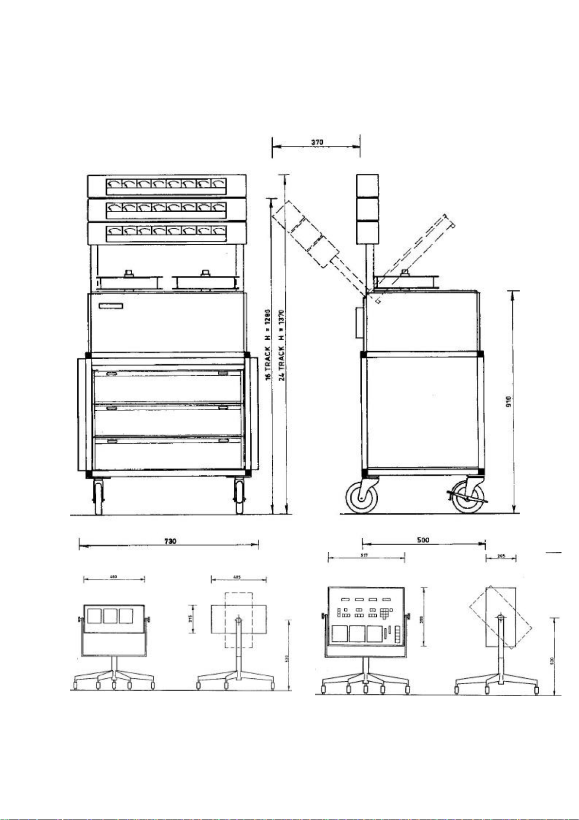
2.2 DIMENSIONS
Remote control type RCU Remote control type TPC
1977-05-01 TR532
1977-05-02 2.2
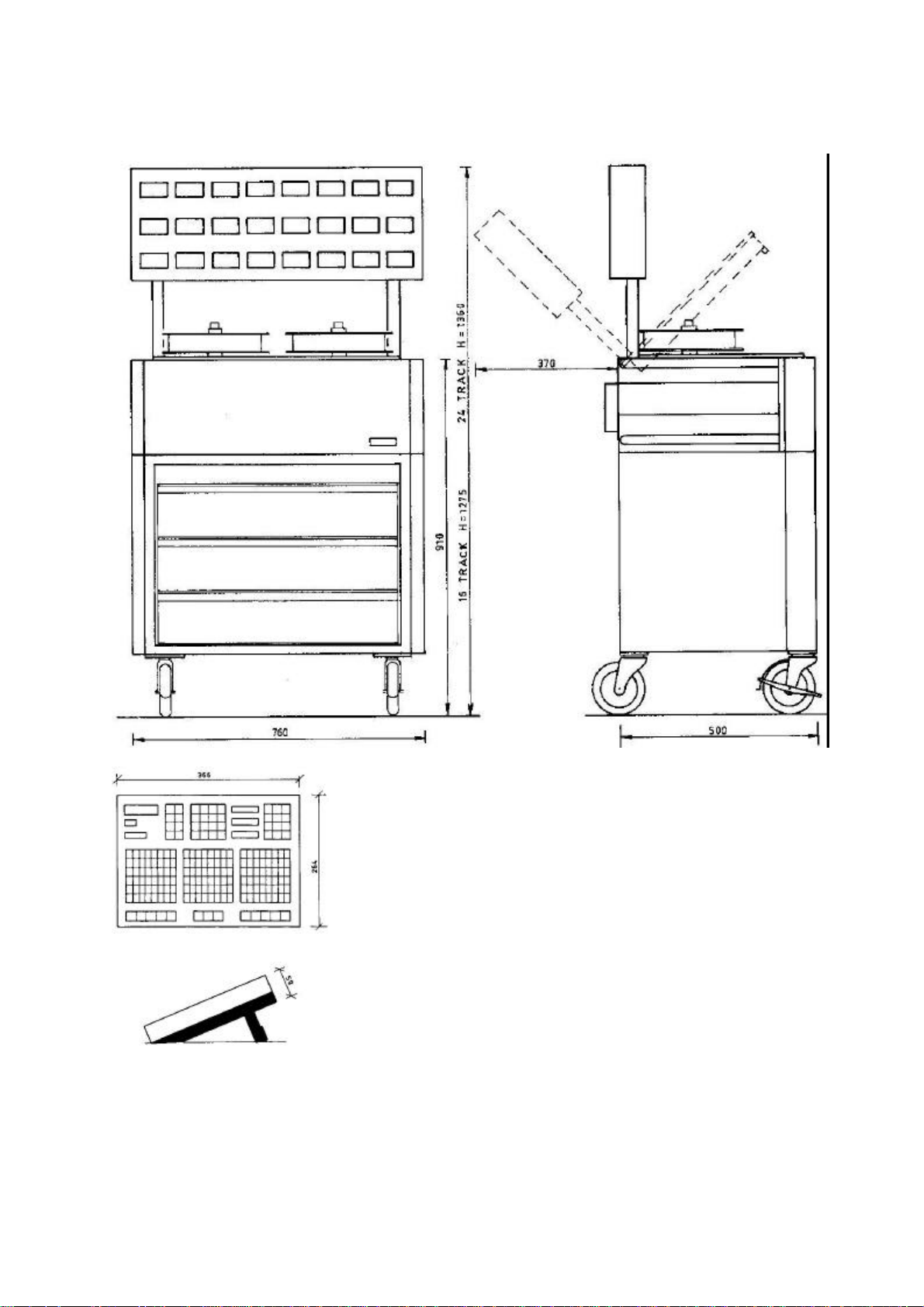
Remote Control type ATC
1984-05-17 TR532 2.2

2.3 LIST OF ACCESSORIES
1 Tool case, plastic
1 Set of Allen keys 1.5, 2, 2.5, 3 mm
1 Allen key 3 mm x 90 mm
1 Allen key 2 mm x 90 mm
1 Screwdriver 80 mm x 2 mm, Belzer
1 Oilcan, mini Belzer, with Esso NUTO HP 32
1 Bottle of cleaning fluid
1 Bag of Q-tips
2 Double air filter
5 Telephone lamp 36 V, 50 mA
1 Minilamp 28 V, 40 mA
4 Fuse 2 A slow
2 Fuse 4 A slow
2 Mains cable, 3 m
1 Test cable 1.5 m coax with jack and banana plug
1 Manual
1 Dust cover
1 Remote control unit extension card
For each 8-track unit;
4 12 pole connector Siemens C42334-A41-A3
4 Connector housing Siemens C42334-A228-A842
2 9 pole connector Cannon DE-9P
2 Connector housing Cannon DE51218-1
1977-05-01 TR532

2.3 LIST OF ACCESSORIES
969002 1 Tool case, plastic
969011 1 Set of Allen keys 1.5, 2, 2.5, 3 mm
969016 1 Allen key 3 mm x 90 mm
969017 1 Allen key 2 mm x 90 mm
969020 1 Screwdriver 80 mm x 2 mm, Belzer
969036 1 Oilcan with Esso NUTO HP 32
501009 2 Double air filter
961701 5 Telephone lamp 36V, 5OmA
922134 2 Lamp EAO 11.903.0 for ATC
961711 1 Minilamp 28V, 4OmA
961920 4 Fuse 2A slow
961941 2 Fuse 4A slow
961910 2 Fuse 1A slow
999999 1 Mains cable 3 m
501027 1 Test cable 1.5 coax with jack and banana plug
969044 1 Manual
969046 1 Manual for ATC
501028 1 Extender print for AM77
953701 1 25 pole connector Cannon DB25P - male
953702 1 Connector housing Cannon DB115339-2
999999 4 Allen screw M3 x 8 ULS
999999 4 Allen screw M4 x 10 ULS
999999 24 Screw M3 x 10
869583 1 Brake band
For each 8 track unit;
954409 4 12 pole connector Siemens C42334-A41-A3
954408 4 Connector housing Siemens C42334-A228-A842
953743 1 9 pole connector Cannon DE-9P
953746 1 Connector housing Cannon DE51218-1
1984-06-12 TR532 2.3

GENERAL DESCRIPTION
3.1 SERVICE MANUAL
This manual covers the description, installation, operation and
service instructions for the Lyrec TR532-series of 2" and 1"
professional tape recorders. The available configurations are the
following
- TR532-8. 1" 8 track recorder
- TR532-16, 2" 16 track recorder
- TR532-24, 2" 24 track-recorder
It is possible to change these configurations in the field by means of
interchangeable head blocks and rollers.
3.2 TAPE DECK
The TAPE DECK has a very compact and clean layout. The head screen is
easily removable without any tools. Tape path is simple and tape is
easy to thread.
The nominal tape speeds are controlled by a DC-motor which may be set
internally to two fixed nominal speeds or varied over a wide range.
It may also be controlled from an external source enabling two or more
machines to be syncronized together via external equipment (i.e.
MagLink, Minimag or similar).
Tape tension on either side of the capstan is maintained within
working limits by servo controlling the wind motors by way of their
respective tape tension sensing arm assemblies.
The tape transport function controls are situated along the front of
the TAPE DECK towards the left. Normal functions include START, STOP
and RECORD buttons, all illuminated, as also the WIND button which
activates the WIND SPEED CONTROL placed in the middle of this group.
This control allows for infinitely variable speed increments in the
wind mode in either direction.
Near the pinch roller is the EDIT CONTROL. This prevents the pinch
roller to press the tape against the capstan but allows all other
functions. In this way spot erase of single channels may be effected
by hand.
At the extreme right of the front edge of the tape deck is the
illuminated MAINS on/off button, which also carries a safety feature.
It will not disconnect the machine until the STOP MODE has been
reached. In this way tape spills and accidental recording
interruptions are avoided.
1977-05-01 TR532 3.2

Close to the MAINS button are the two speed selection buttons, 15 and
30 ips. When power has been switched off the tape recorder will always
come back to the previously selected speed.
The power supplies for the machine are housed below the tape deck,
together with the servo electronics.
3.3 RECORD/PLAYBACK AMPLIFIERS AM 77
The RECORD/PLAYBACK AMPLIFIERS are housed in 8-track units below the
mechanical section of the machine. One complete RECORD/PLAYBACK
AMPLIFIER AM 77 is contained on a single printed board. All necessary
adjustments are made from the front and each amplifier is an easily
replaceable plug-in unit.
Equalization amplifiers, level control and bias level control are
contained on plug-in boards on the AM 77. This allows easy changing
from standard version to any other version by plugging in the correct
equalization boards.
Furthermore there is a possibility of letting the tape speed
pushbuttons control the amplifiers only. In this way a 15 ips CCIR 15 ips NAB recorder is obtained.
For purposes where it is necessary to change bias level on a few
tracks on a prerecorded tape, a switch is installed on each amplifier.
An arbitrary bias value may then be set without disturbing the two
normal bias settings.
3.4 VU-METER PANEL
The VU-METER PANEL is mounted at the rear top of the TAPE DECK. It may
be mounted at any remote location if the user so desires. Each VUMETER may be calibrated over a wide range of levels to suit individual
studio requirements.
3.5 CONSOLE
The TAPE DECK, RECORD/PLAYBACK AMPLIFIERS and VU-METER PANEL are
mounted in a solid framework on large casters which aid moving the
machine around. The three sections are electrically interconnected
with cable harnesses which are long enough to allow good service but
which are placed at the rear of the machine where they are out of the
way in normal use.
1977-05-01 TR532 3.5

All heat producing elements are located at the rear of the machine so
that the sides may be placed in direct contact with other equipment,
thereby taking up a minimum of control room space.
Low-noise fans further enhance the temperature safety margin.
3.6 REMOTE CONTROL UNIT
A normal feature of the machine is a very complete REMOTE CONTROL
UNIT; facilities include the possibility of switching the output
signal of each channel between the LINE input, the SYNC output and the
PLAYBACK output. It is possible to drop in or out of record on any
individual channel. A SOLO button is also provided for each channel.
The switching logic for these functions is so designed as to simplify
the operators requirements in so far as routing systems and working
requirements are concerned. This allows the use of simpler desks or
less tiring work routines.
Further features of the REMOTE CONTROL UNIT include VARISPEED
continuously covering the range 7.5 to 60 ips. Actual tape speed can
be monitored by the TAPE TIMER DISPLAY enabling any VARISPEED setting
to be repeated accurately. A SEARCH FUNCTION is provided whereby the
machine can rewind to any pre-selected position of the tape, with no
overshoot.
The normal tape transport functions START, STOP, RECORD and FAST WIND
modes are also present in the REMOTE CONTROL UNIT. There is a socket
on the rear of the box enabling a REMOTE TIMER DISPLAY to be installed
up to 10 meters away from the box, in any convenient control room
location.
1977-05-01 TR532 3.6

4. INSTALLATION
4.1 UNPACKING
The machine has been packed in a container specially designed for air
freight. Inspect it visually and if any damage is observed notify your
carrying agent immediately. If all is normal unpack the machine
carefully and retain the packing material for possible future use.
Remove the front and side covers of TAPE DECK and inspect the SERVO
CONTROL print boards; they should be firmly seated in their positions,
and all connectors should be likewise.
Inspect the TAPE DECK and check that none of the metal parts that come
in contact with the tape are damaged in any way.
Check the HEAD BLOCK and particularly the front of the head stacks.
Rubber rollers should be smooth and all metal rollers should move
freely; tension arms should feel slightly hard because of the damping
cylinders but movement should be smooth, with no indication of
friction or roughness.
Check the seating of the individual RECORD/PLAYBACK AMPLIFIERS
modules.
Refer to the CONNECTOR TABLE below and check that all factory wired
plugs and connectors are properly in place.
Proceed likewise with the REMOTE CONTROL UNIT and the VU-METER PANEL.
Place the VU-METER PANEL in position and secure it with the four
screws provided.
4.2 INTERCONNECTION
After checking the above refer to the CONNECTOR TABLE again and the
CONNECTOR DIAGRAMS and wire up the mains connectors. BE SURE YOUR
LOCAL MAINS VOLTAGE IS COMPATIBLE WITH THE MACHINE. BE SURE THAT YOU
COMPLY WITH YOUR LOCAL REGULATIONS AND PAY PARTICULAR ATTENTION TO THE
EARTHING CONNECTIONS. Then wire up all the LINE IN and LINE OUT
connectors the RECORD INDICATION connectors, where applicable, and the
SYNC OUTPUT connectors.
Connect the REMOTE CONTROL UNIT umbilical to the connector on the rear
of the tape deck.
CAUTION: THIS CONNECTION SHOULD NOT BE MADE OR BROKEN WITH EITHER
MACHINE OR THE REMOTE CONTROL UNIT OR BOTH SWITCHED ON.
DAMAGE TO THE DIGITAL CIRCUITRY WILL ENSUE.
This completes the installation procedure.
1977-05-01 TR532 4.2
Mating connector
NO Designation Connector
1 LINE IN 1-4
(5-8)(9-12)(13-
16) (17-20)(21-
24)
2 LINE OUT 1-4
(5-8)(9-12)(13-
16) (17-20)(21-
24)
3 Record
Indication
4 SYNC OUT B To external
5 POWER C Power supply in
6 VU-METERS D To VU meter
7 REMOTE CONTROL
A
8 REMOTE CONTROL
B
9 ERASE HEAD E To erase head FACTORY
10 RECORD HEAD E To record head FACTORY
11 PLAYBACK HEAD E To playback head FACTORY
12 220 V 50 Hz G From mains
13 Ext. motor
control
14 Remote control
Tape deck
15 220 V 50 Hz G From mains
16 Slave display J To slave display
1977-05-01 TR532
CONNECTOR TABLE
type
from/to
A From external
signal source
A To external
equipment
B To noise
reduction
equipment
equipment
tape deck
panel
D To remote
control unit
C To remote
control unit
supply
H From external
speed control
equipment
I From remote
control unit
supply
Mating
connector
wired by
User
USER
USER
USER
FACTORY
FACTORY
FACTORY
FACTORY
FACTORY
USER
FACTORY
FACTORY
USER/FACTORY
Electronics
Tape Deck
Remote
control

CONNECTOR TYPES
Type Chassis Connector Mating Connector
A Siemens C42334-A41-A4 with
tray C42334-A228-C92
Siemens C42334-A41-A3
with shell C42334-A228-A842
B Cannon DE-9S Cannon DE-9P
with Shell Cannon DE51218-1
C Cannon DB-25P Cannon DB25S with shell
DB115339-2
D Cannon DB25S Cannon DB25P with shell
DBI15339-2
E Siemens A42334-A44-A4
with tray A42334-A228-C95
F Siemens A42334-A44-A3
with tray A42334-A228-C95
Siemens A42334-A44-A3
with shell A42334-A228-A845
Siemens A42334-A44-A4
with shell A42334-A228-A845
G Otto Heil 6061-1 Otto Heil 4010
H Amphenol-Tuchel T3262 Amphenol-Tuchel T3261/1
I Amphenol-Tuchel 2071-030
with tray 1136-002
J Amphenol-Tuchel 2009-012
with tray 1148-002
Amphenol-Tuchel 2070-030
with shell 1124-001
Amphenol-Tuchel 2008-012
with shell 1122-001
1977-05-01 TR532
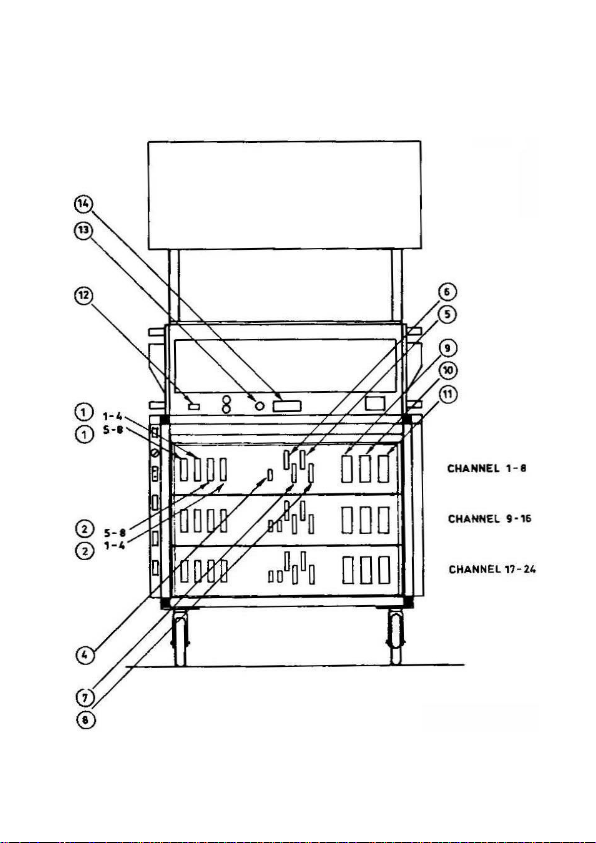
Rear view, connector numbers shown without cables
1977-05-01 TR532
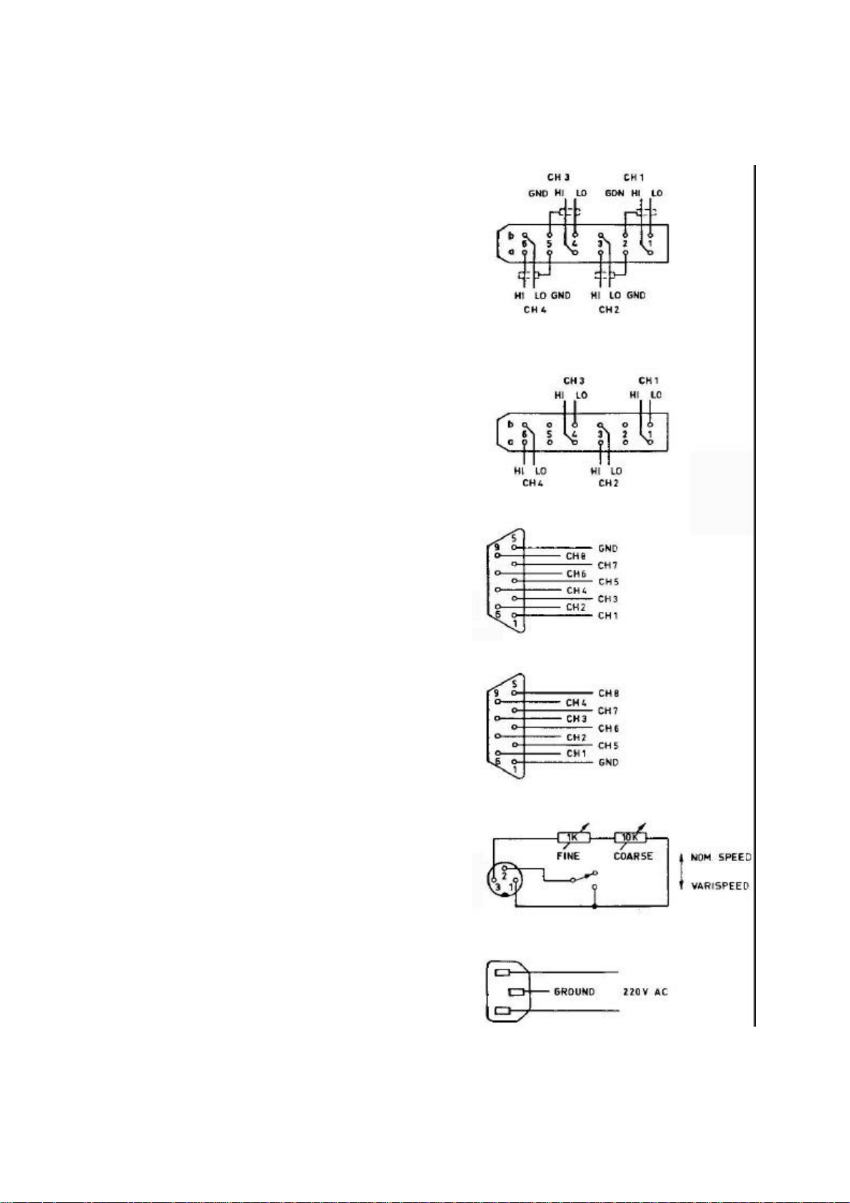
CONNECTOR DRAWINGS
No. I LINE IN 1-4
(5-8, 9-12, 13-16, 17-20,
21-24)
(all grounds internally
connected)
No. 2 LINE OUT 1-4
(5-8, 9-12, 13-16, 17-20,
21-24)
(pins 2a, 2b, 5a, 5b not
connected)
No. 3 RECORD INDICATION 1-8
(9-16)(17-24)
When a channel is in RECORD,
output will be +24 V, other
wise a high impedance to ground.
Ext. load min 3 Kohms.
No. 4 SYNC OUT 1-8
(9-16, 17-24)
Ext. load min 10 kOhms
No. 13 Ext. Motor Control
Note: Do not use this circuit
simultaneously with Varispeed
from Remote Control Unit.
No. 12, 15
All connectors are cablepart seen from solderside.
1977-05-01 TR532
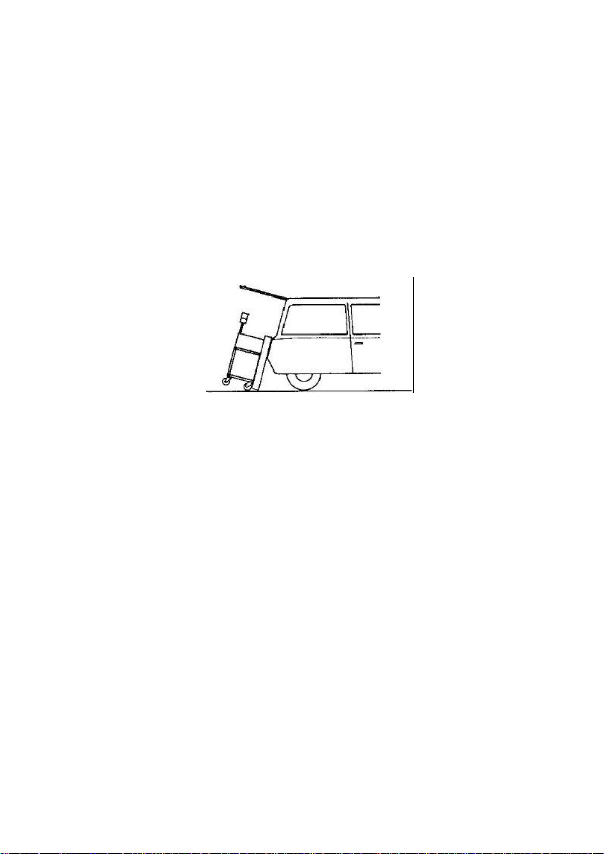
4.5 TRANSPORTATION
The Lyrec TR532 can be transported in a car or van. During transport
it can either stand up or be laid down on it's front. For this purpose
the factory has developed a special transport frame that fits the
front of the recorder (see section 6.7).
Move the recorder close to the back of the vehicle and place the
transport frame on the front of the machine. Tilt the recorder into
place and slide it in. This operation can easily be made by two
people.
1977-05-01 TR532 4.5

5. OPERATION
5.1 SWITCHING ON
Connect both line cords to the appropriate voltage and press the MAINS
button on the tape deck. Select the desired tape speed. The MAINS, the
STOP and one of the speed buttons on the TAPE DECK and the STOP button
on the REMOTE CONTROL UNIT should light up. The ventilation fans
should start running and the VU-meters should light up (if of
illuminated type).
Switch on the REMOTE CONTROL UNIT; the power switch is on the rear
panel. All channels should illuminate their SAFE and SYNC LED'S. The
TAPE TIMER should indicate 00.00 and the speed should be set at
nominal speed, whichever has been selected.
TAPE DECK
5.2 LOADING
Place an empty reel and a full reel on the appropriate hubs. The
knurled knob on the top of the hub should be turned clockwise to lock
the reels in place. Refer to drawing No. 5.02 and thread the tape
through the tape path. Check the height of the tape, and if necessary
adjust it. See section 7.1 for this adjustment.
5.3 PLAY MODE
Press START button on the TAPE DECK or on the REMOTE CONTROL UNIT.
Both buttons should illuminate; the PINCH ROLLER and GUIDE ROLLER
should pull in, placing the tape in contact with the heads and the
capstan, which will cause the tape to move forward at its nominal
speed.
On the REMOTE CONTROL UNIT the timer will begin to show seconds and
then minutes of elapsed time. Select REPRO on the REMOTE CONTROL UNIT
on those channels from which the tape playback signal is to be
monitored.
5.4 RECORD MODE
Select the channels to be recorded on the REMOTE CONTROL UNIT by
pressing the READY buttons on the appropriate channels; the red LED's
will immediately begin flashing to indicate that these channels are
ready to record. On the same channels the green SAFE LED will go off.
Press RECORD and START buttons simultaneously either on the TAPE DECK
or on the REMOTE CONTROL UNIT; the same mechanical functions as in the
play mode will occur. On the REMOTE CONTROL UNIT the red flashing
LED's will illuminate steadily indicating RECORD MODE on those
channels.
1977-05-01 TR532 5.4
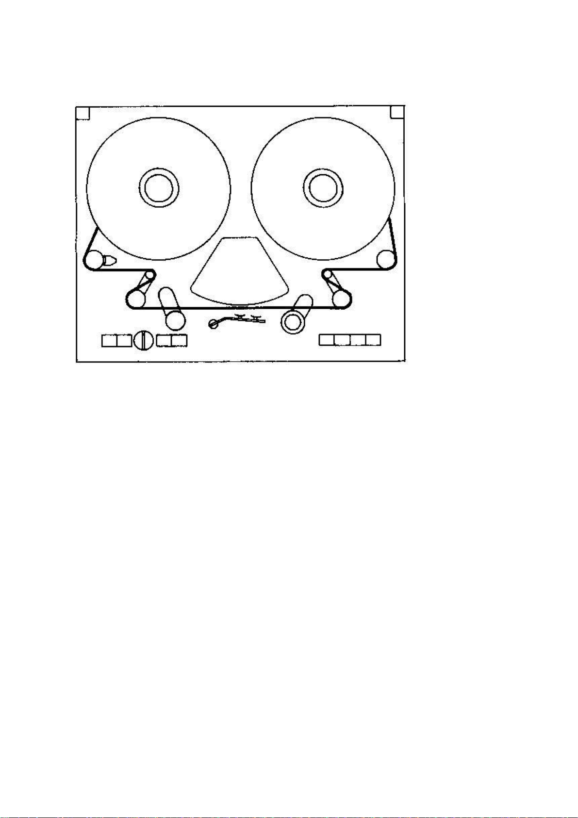
Drawing No. 5.02, Tape path
1977-05-01 TR532

5.5 FAST WIND MODE
A. From the TAPE DECK
Press the WIND button and select the direction and speed of wind by
setting the WIND SPEED CONTROL.
B. From REMOTE CONTROL UNIT
Press the appropriate button to select wind direction and alternate
with the other to control speed.
5.6 EDIT MODE
Turn the EDIT CONTROL in anti-clockwise direction, thereby causing the
tape to come into contact with the PLAYBACK head but not with the
capstan. The SERVO TENSION ARMS are locked and the tape path is now
rigid. For convenience the head shields may be removed by simply
pulling up, when commencing the operation.
Any of the previous modes may be used simultaneously with the EDIT
MODE allowing editing in the PLAY MODE, searching in the WIND MODE or
hand controlled spot-erasing in the RECORD MODE. It is also possible
to enter the EDIT MODE from any of the previous modes.
5.7 STOP MODE
Pressing the STOP button immediately interrupts the PLAY or RECORD
modes. In both cases the tape motion is immediately halted and the
tape is lifted from the heads. Coming from the RECORD MODE the
electronics are also switched to a stand-by condition, see below.
When coming from the FAST WIND mode dynamic brakes are first applied
to slow the reels and when the tape motion sensor indicates that the
tape is halted then mechanical brakes are applied, simply to hold the
reels in place.
5.8 TAPE DECK LOGIC
The TAPE DECK SERVOSYSTEM and LOGIC is so designed as to avoid
throwing tape loops or causing spills, jerks or other situations
dangerous to the tape. It is possible to go from any mechanical mode
to any other with no problems. For description of the circuits, see
section 8.
REMOTE CONTROL UNIT
Channel function selectors.
5.9 READY
As previously indicated these buttons select a given channel and place
it in READY MODE so that when the START and RECORD buttons are pressed
the channel goes into RECORD MODE. In the READY MODE
1977-05-01 TR532 5.9

the red LED flashes continuously; when the machine is placed in the
RECORD MODE the flashing stops and the LED glows steadily. If a READY
button is pressed when the machine is already in the RECORD MODE this
channel will not drop into RECORD MODE although the LED will start
flashing. It will stay in the READY MODE until the START and RECORD
buttons are again pressed simultaneously. Doing this has no effect on
the tape motion; it simply drops the new READY channels into the
RECORD MODE. (As a special option it is possible to add a switch to
the REMOTE CONTROL UNIT which will allow the READY button to drop a
channel directly into RECORD MODE when either RECORD button has been
selected and the machine is already in motion.)
5.10 DROP IN/OUT CAPABILITY
If it is necessary to pre-select a certain track or group of tracks,
to drop in and out of them continuously, the following procedure is
used:
Select the tracks by means of the READY buttons. Then press the START
button; to drop in press both START and RECORD buttons. To drop out
keep START pressed and momentarily press the STOP button; the tracks
will stop recording but tape motion will not be interrupted and the
READY pre-selection will be maintained.
5.11 SAFE
When pressed the individual channel SAFE buttons illuminate a steady
green LED. In this condition a channel cannot go into the RECORD MODE
even though the RECORD MODE may be selected by pressing the START and
RECORD buttons. As a further feature there is a master SAFE button
which throws all the channels of the machine into SAFE MODE. The SAFE
MODE may be used also as a "drop-out" from the RECORD MODE and may be
activated during RECORD MODE without interrupting the tape motion.
To review these functions:
A channel will only go to RECORD at the moment where RECORD and START
are pressed simultaneously, and only if it before that moment was in
READY.
To get channels out of RECORD several ways exist:
1. STOP. The tape will stop. Channels in RECORD will go to READY.
Channels in READY will stay in READY.
2. Master SAFE. The tape will continue. Channels in RECORD and READY
will go to SAFE.
3. Individual SAFE. The tape will continue. That particular channel
will go to SAFE. No other channels will change state.
4. START and momentarily STOP. The tape will continue. All channels in
RECORD will go to READY. No other channels will change state.
1977-05-01 TR532 5.11

5.12 LINE/SYNC/REPRO
The LINE OUT signal from each PLAYBACK AMPLIFIER may be selected by
one of the three following controls: LINE, SYNC and REPRO. This does
not affect the recording on this track.
Pressing the LINE button selects the LINE INPUT signal of that channel
and routes it to the output.
Pressing the SYNC button selects the signal from the record head of
that channel, used as a playback head.
Pressing the REPRO button for that channel selects the signal from the
normal playback head.
There are also three master buttons for LINE, SYNC and REPRO which
will throw all the channels to that particular function.
The only exception to these selections occurs when a given channel is
selected to SYNC and it is also placed in the RECORD MODE. In this
situation the channel is automatically switched to LINE, returning to
SYNC when the RECORD MODE is cancelled.
5.13 SOLO/DEFEAT
When the SOLO button of a channel is pressed it causes all the other
channels to switch to LINE. (This can be changed on special order so
that the other channels mute instead of switching to LINE.) Any amount
of channels may be soloed simultaneously. In order to return them to
their normal situation the DEFEAT button is pressed.
5.14 TAPE TIMER
The TAPE TIMER receives information from the tape motion sensor on the
tape deck, and shows elapsed time in minutes and seconds relative to
15 ips. By means of the RESET button on the left, it may be reset to
00.00 at any point desired by the operator. In order to avoid
accidental resets this button has a protective cover.
5.15 SEARCH FUNCTION
The SEARCH FUNCTION comprises two controls, an illuminated SEARCH
button and a PRESET DIAL. When the SEARCH button is pressed the TAPE
DECK goes into the WIND MODE and automatically winds the tape in such
a way as to make the timer display equal to the display on the PRESET
DIAL. A built-in feature of this function ensures that the tape will
not overshoot since the wind speed is progressively lowered as soon as
the difference between the two displays drops below a preset amount.
1977-05-01 TR532 5.15

5.16 NOMINAL/VARISPEED
When the NOMINAL button is pressed the LED lights up and the machine
will transport the tape at fixed nominal speed of 15 or 30 ips,
whichever has been selected. When the VARISPEED button is pressed the
LED flashes continuously to warn of a non-normal condition; the speed
of the tape now depends on the setting of the two potentiometers below
the VARISPEED button. As indicated they allow COURSE and FINE
adjustments of the tape speed from slightly below 7 1/2 ips to
slightly above 60 ips. A further feature of both buttons, in
combination with the TAPE TIMER display allows for checking the actual
tape speed. This is operated as follows: Select either the NOMINAL
speed or VARISPEED. Do not release the selector button but hold it
down. In this position the TAPE TIMER display will change over to 4
digits which express the actual tape speed according to the following
formula:
1000
speed ips = 15 x
2.000 - DISPLAY
Table 1 and 2 shows the full range of the displays with their
equivalents in speed deviation in ips, in percentage or in musical
values. This speed checking function may be used to reset any
VARISPEED setting at any time within close tolerances.
An important feature of this function is that it does not disturb the
TAPE TIMER counting. When the button is released the timer will go
back to its normal timing function without having lost count in the
interval.
Note: No reading will result if the tape is not in motion,
since the information is taken from the TAPE MOTION SENSOR,
therefore reflecting the actual tape motion, not the capstan
motor speed.
1977-05-01 TR532 5.16

TABLE 1; nominal speed 15 ips. Applicable for standard REMOTE
CONTROL UNIT, RCU
Display Speed (ips) Deviation %
0000 7.50 - 50.00
0100 7.89 - 47.37
0200 8.33 - 44.44
0300 8.82 - 41.18
0400 9.38 - 37.50
0500 10.00 - 33.33
0550 10.34 - 31.03
0600 10.71 - 28.57
0650 11.11 - 25.93
0700 11.54 - 23.08
0750 12.00 - 20.00
0800 12.50 - 16.67
0850 13.04 - 13.04
0865 13.22 - 11.89 - 1 tone
0900 13.64 - 9.09
0902 13.66 - 8.93 - 3/4 tone
0920 13.89 - 7.41
0937 14.11 - 5.93 - 1/2 tone
0940 14.15 - 5.66
0953 14.33 - 4.49
0960 14.42 - 3.85
0969 14.55 - 3.01 - 1/4 tone
0980 14.71 - 1.96
0985 14.78 - 1.48
1000 15.00 0
1015 15.23 1.52
1020 15.31 2.04
1029 15.45 2.99 + 1/4 tone
1040 15.63 4.17
1043 15.67 4.49
1056 15.89 5.93 + 1/2 tone
1060 15.96 6.38
1080 16.30 8.70
1082 16.34 8.93 + 3/4 tone
1100 16.67 11.11
1106 16.78 11.86 + 1 tone
1150 17.65 17.65
1200 18.75 25.00
1250 20.00 33.33
1300 21.43 42.86
1350 23.08 53.85
1400 25.00 66.67
1450 27.27 81.82
1500 30.00 100.00
1977-05-01 TR532 5.16 cont.

TABLE 2; nominal speed 30 ips. Applicable for standard REMOTE
REMOTE CONTROL UNIT, RCU
Display Speed (ips) Deviation %
1000 15.00 - 50.00
1050 15.79 - 47.37
1100 16.67 - 44.44
1150 17.65 - 41.18
1200 18.75 - 37.50
1250 20.00 - 33.33
1275 20.69 - 31.03
1300 21.43 - 28.57
1325 22.22 - 25.93
1350 23.08 - 23.08
1375 24.00 - 20.00
1400 25.00 - 16.67
1425 26.09 - 13.04
1432 26.43 - 11.89 - 1 tone
1450 27.27 - 9.09
1451 27.32 - 8.93 - ¾ tone
1460 27.78 - 7.41
1468 28.22 - 5.93 - ½ tone
1470 28.30 - 5.66
1476 28.65 - 4.49
1480 28.85 - 3.85
1484 29.10 - 3.01 - ¼ tone
1490 29.41 - 1.96
1492 29.56 - 1.48
1500 30.00 0
1507 30.46 1.52
1510 30.61 2.04
1514 30.90 2.99 + ¼ tone
1520 31.25 4.17
1521 31.35 4.49
1528 31.78 5.93 + ½ tone
1530 31.91 6.38
1540 32.61 8.70
1541 32.68 8.93 + ¾ tone
1550 33.33 11.11
1553 33.56 11.86 + 1 tone
1575 35.29 17.65
1600 37.50 25.00
1625 40.00 33.33
1650 42.86 42.86
1675 46.15 53.85
1700 50.00 66.67
1725 54.55 81.82
1750 60.00 100.00
1977-05-01 TR532 5.16 cont.

RECORD/PLAYBACK AMPLIFIERS
5.17 SYNC OUTPUT
Apart from the normal sync signal which is routed to the LINE OUTPUT
each AM 77 RECORD/PLAYBACK AMPLIFIER incorporates a separate sync
amplifier. The signal from this extra sync output is available
independently for each channel at a separate plug. This output is
unbalanced and should not be terminated with less than 10 kOhms.
The SYNC OUTPUT does not in any way affect or interfere with the
ordinary sync signals available at the line output, nor can it be
controlled by the SYNC button on the REMOTE CONTROL UNIT.
1977-05-01 TR532 5.17

5.18 SPECIAL FEATURES
The machine has been designed for maximum ease of operation. In this
context several facilities have been included which are not normally
found as standard items.
HEADBLOCK
To ease maintenance and format changes the HEADBLOCK uses a plug and
socket interconnection with a precision mechanical seating arrangement
that allows fast changeover operations.
EDITING FACILITIES
As described (5.6) the EDIT CONTROL not only permits splice editing
but also provides for very precise spot erasing with the RECORD MODE
activated and the tape moved by hand. Holding the EDIT CONTROL half
way in during FAST WIND permits listening to the tape without close
contact to the playback head.
SWITCH-OFF SAFE-GUARD
As mentioned (3.2) the MAINS SWITCH will not switch off the machine
unless it is in STOP MODE. This avoids accidental tape spills or
interruptions.
SPEED MEMORY
When mains is switched on and off the taperecorder always comes back
to the same speed. Change between the two nominal speeds can only be
done in STOP MODE.
TRANSIENT PROTECTION
To avoid strong switch-on and switch-off transients in the outputs,
which might damage monitor speakers, a relay has been included which
short-circuits the output of the playback amplifiers for a few seconds
after power is applied, until DC conditions are stabilized, and also
immediately after it has been removed, before DC working conditions
can change.
RECORD INDICATION OUTPUT
A socket is provided on the back of each eight-channel unit, which
delivers +24 V from each individual channel when it goes into the
RECORD MODE, enabling external equipment-functions to be controlled
(i.e. noise reduction). In other modes the RECORD INDICATION OUTPUT
has a high impedance to ground external load: min 3000 ohms.
SEARCH FUNCTION
As described (5.15) the SEARCH FUNCTION is a useful aid in speeding up
working routines; it is built into the machine and requires no extra
hardware or powering.
1977-05-01 TR532 5.18

SOLO buttons
This facility (5.13) is most useful when mixing but it does not affect
any other function of the machine and can be used at any time to check
the contents of any individual track.
SPEED CHECK
Using an internal crystal reference the machine provides an easy check
on its performance and the calibration of the VARISPEED settings
without recourse to outside instrumentation. (See 5.16)
VARISPEED
Again no outside hardware is necessary to provide a facility (5.16)
which, in combination with a speed check, becomes a highly useful
tool.
EXTERNAL SPEED CONTROL
An extension of the previous circuit allows the machine to be
controlled from an external source or synchronized with other machines
or equipment.
SYNC OUTPUT
This facility (5.17) is most useful for effects purposes, for example
phasing, single shot repeats, phrasing corrections, double tracking,
noise gate key control, compressors in parallel, etc. where it is
necessary to have available both the SYNC and the PLAYBACK signals
from the same channel. Some examples are presented in section 10,
Application notes.
MUTING
To protect your speakers there is a muting device on the LINE OUTPUT.
In STOP and WINDING MODES all outputs are muted. This muting can be
cancelled in two ways:
a) By turning the EDIT CONTROL on the tape deck.
b) By pressing the DEFEAT button on the REMOTE CONTROL UNIT.
1977-05-01 TRS32 5.18 cont.
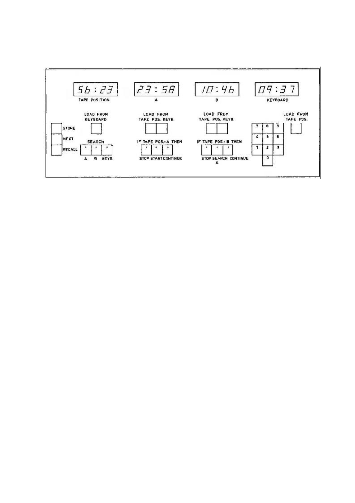
5.19 TAPE POSITION CONTROLLER, TPC (OPTIONAL)
The unit is built up around a four-digit display, TAPE POSITION, which
works as an ordinary tape timer. It counts in minutes and seconds at
the tape speed 15 ips (7 1/2 ips available as option).
Besides the TAPE POSITION-display, there are an A-display, a B-display
and a KEYBOARD-display. The content of the KEYBOARD display is
controlled from the keys 0-9 in the KEYBOARD. When a key is pressed,
the digits in the KEYBOARD-display will roll one position to the left.
The left-most digit will disappear, and the pressed digit will show up
in the right-most position.
Another way of controlling the KEYBOARD-display is through the LOAD
FROM TAPE POSITION-key. When this is activated, the number in TAPE
POSITION will be copied into KEYBOARD. The A and B displays can be
loaded from TAPE POSITION as well as from KEYBOARD, while TAPE
POSITION only can be loaded from KEYBOARD.
If TAPE POSITION is different from A (or B or KEYBOARD), it is
possible to search A (B, KEYBOARD) by activating SEARCH A (B,
KEYBOARD). The unit will cancel the selected machine-function (STOP,
START, RECORD) and through WIND MODE make TAPE POSITION equal to A (B,
KEYBOARD) and end up in STOP (unless something else is selected). This
SEARCH-function can only be cancelled by a STOP-command. During SEARCH
it is not possible to change the contents of the TAPE POSITION-display
and the display which is being searched.
If one of the two keys IF TAPE POSITION = A THEN STOP/START has been
activated, the machine will, when TAPE POSITION displays the same
number as A, carry out the selected function, no matter how the two
numbers have become equal. This will happen every time the two numbers
are equal until the CONTINUE-key is pressed.
1977-05-01 TR532 5.19
 Loading...