

Page 1

Lynxus Technology Copyrights 2016
Lynxus Confidential
Feature..............................................................................................3
Application....................................................................................... 3
Technique Parameters..................................................................... 4
Circuit Description.......................................................................... 4
Pin Description.................................................................................5
Reference application...................................................................... 6
Page 2

Lynxus Technology Copyrights 2016
Lynxus Confidential
Feature
The ZBM-1.0 module is an integral system for IEEE 802.15.4 application. The
CC2530 is the control center in the module, which brings the module the low power
consumption feature. ZBM-1.0 can amplify or sample signals, thanks to its integrated
op-amp and 12 bit ADC(6 Channel). The module provides the reset function, 256 KB
program storage space, and supports USART (full-duplex) or other serial
communication protocol. A number of programmable digital I/O ports are reserved to
increase the interface flexibility between the baseboard and the module.
The module can be configured to use the built-in antenna or external antenna.
RFx2401 on the module, which functions as the RF PA and LNA, provides a stable
2.4G transmitting and receiving channel. This module can be used as an excellent
communicating node in a Zigbee wireless intelligent system.
Application
Zigbee Systems
Home/Building Automation
Lighting Systems
Industrial Control and Monitoring
Low-Power Wireless Sensor Networks
Page 3
Lynxus Technology Copyrights 2016
Lynxus Confidential
Technique Parameters
Table1. Module Parameters
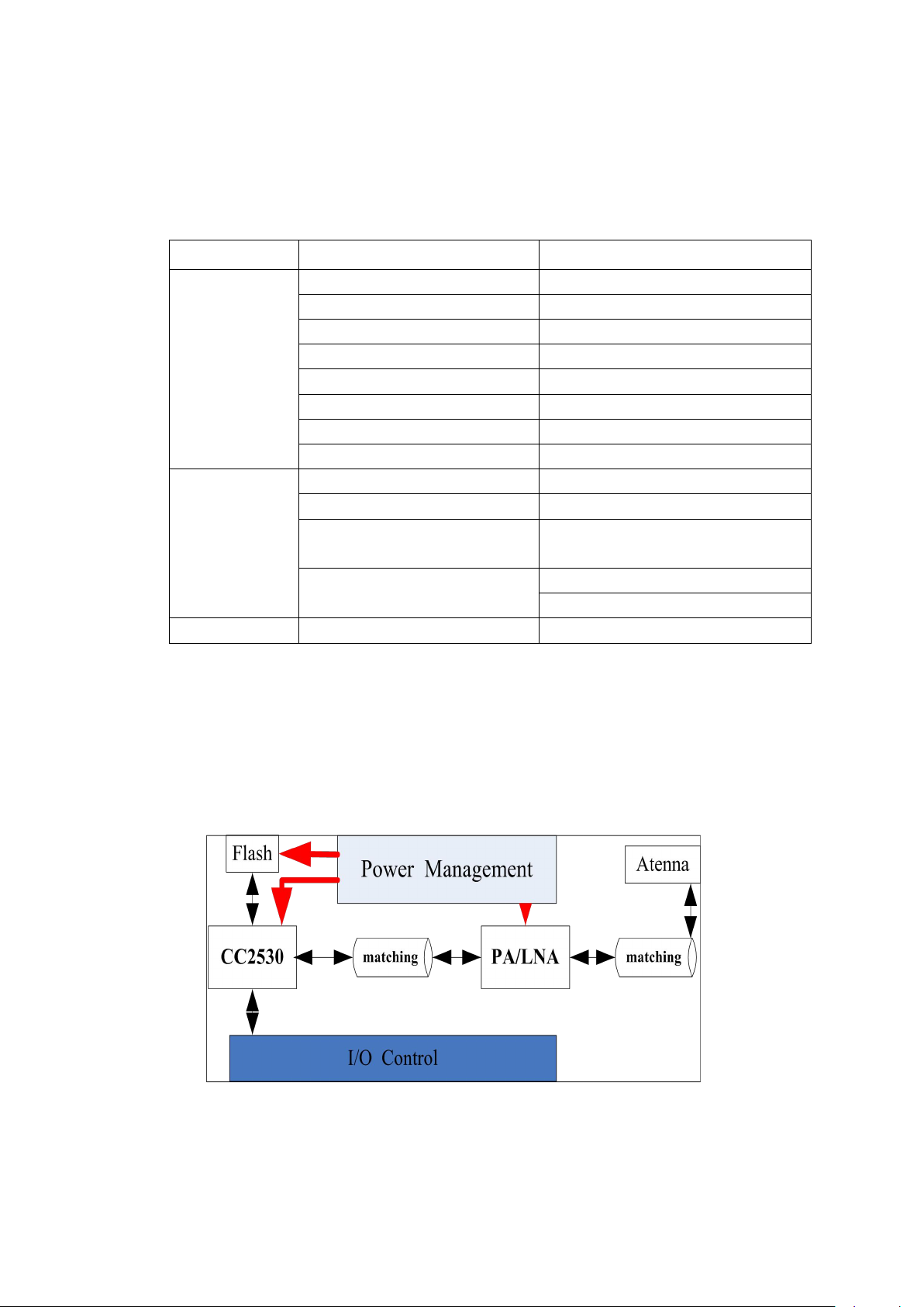
Circuit Description
Figure1. Circuit Diagram
Categories
Feature
parameters
Wireless
specification
Function
transceiver
Protocol
IEEE 802.15.4 /zigbee
Operating Frequency
2.4-2.5Ghz
Max Transmit Power
Receive Sensitivity
Max distance
Data Rate
250Kbps
Impedance
50-Ohm
electrical
specification
Supply Voltage
2.0V-3.6V
Host Interface
UART/SPI
Connect
Internal Antenna or
External Antenna via SMT PAD
Current
Ide:
Active:
physical
Dimensions
30.35mm X14.99mm
Page 4

Lynxus Technology Copyrights 2016
Lynxus Confidential
ZBM-1.0 has an independent power management system, and the system
provides a high quality of power supply for the whole module. Flash is used for the
external expansion memory. The Excellent matching circuit in RF-Front ensures that
the signal has minimal signal loss and radiation. The I/O Control provides the
interfaces for a variety of peripherals (Timer, PWM, Interrupt, AD, the Debug) from
the module to the baseboard. Each peripheral that connects to the module I/O pins can
choose between two different I/O pin locations with the provided flexibility in various
applications.
Pin Description
Tabel2. Module Pin
Note: According to your actual application, the I/O port pins can be configured to
No.
Name
Mode
description
1
NC
2
NC
3
GND
Ground
Connected to ground plane
4
VCC
Power
2–3.6V power-supply
5
RST
Digital Input
Reset, active-low
6
P1.0
Digital I/O
7
P1.1
Digital I/O
8
P1.2
Digital I/O
9
P1.3
Digital I/O
10
P1.4
Digital I/O
11
P1.5
Digital I/O
20-mA drive capability
12
P1.6
Digital I/O
13
P1.7
Digital I/O
14
P2.0
Digital I/O
15
P2.1
Digital I/O
16
P2.2
Digital I/O
17
P2.3
Digital I/O
18
P2.4
Digital I/O
19
P2.5
Digital I/O
20
P2.6
Digital I/O
Page 5
Lynxus Technology Copyrights 2016
Lynxus Confidential
different functions.
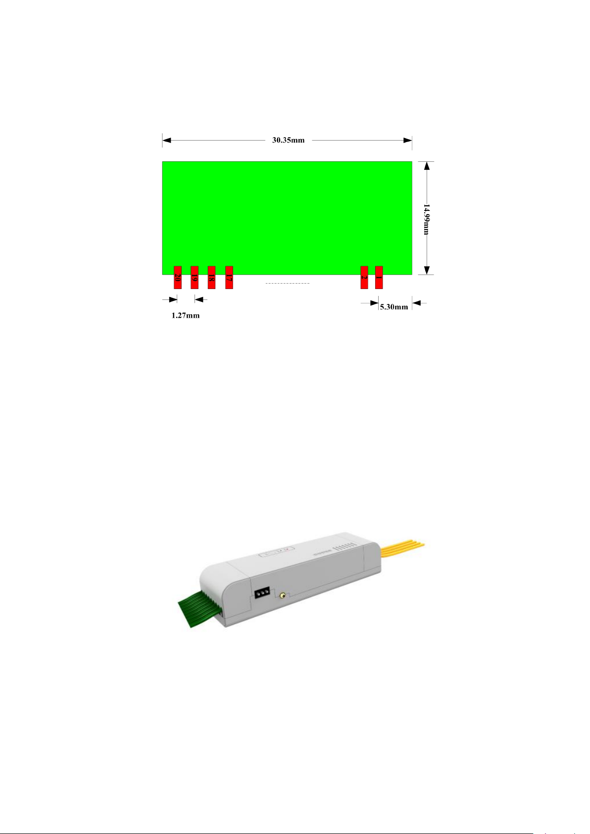
Pin Definition:
Figure2. Pin Definition
Reference Application
The ZBA-B is an intelligent lighting control device that contains ZBM-1.0
module. The ZBA-B product is shown as follows:
Figure3. ZBA-B
ZBA-B uses ZBM-1.0 module to send and receive the commands from the
gateway to turn on/off the connected light or adjust its brightness and color. At the
Page 6

Lynxus Technology Copyrights 2016
Lynxus Confidential
same time, ZBA-B can also report the light’s state or related data to the gateway.
ZBM-1.0 Module is the end device, which establishes wireless connection
between ZBA - B and gateway, and in this application, a large number of tests have
shown that the module applied in intelligent housing system has good stability,
reliability under low power consumption.
When the module is used for ZBA - B, the pins are defined as follows:
Table3. ZBA-B Pin Description
No.
Name
Mode
description
1
NC
2
NC
3
GND
Ground
4
VCC
Power
External power input
5
RST
Digital Input
Power on reset
6
P1.0
Reserved
7
P1.1
Reserved
8
P1.2
PWM1
Color dimming ( RGBW)
9
P1.3
PWM2
Color dimming( RGBW)
10
P1.4
PWM3
Color dimming ( RGBW)
11
P1.5
PWM4
Color dimming ( RGBW)
12
P1.6
Test Mode
Test Flag
13
P1.7
0-10V PWM
Drive power driver
14
P2.0
RGBW Switch
RGBW Switch signal
15
P2.1
Reserved
16
P2.2
Reserved
17
P2.3
Reserved
18
P2.4
Reserved
19
P2.5
Status Indicator Led
20
P2.6
0-10V PWM Switch
Page 7

Federal Communication Commission (FCC) Radiation Exposure Statement
The device has been evaluated to meet general RF exposure requirement,
FCC statements:
The device can be used in portable exposure condition without restriction
This device complies with part 15 of the FCC rules. Operation is subject to the
following two conditions: (1) this device may not cause harmful interference, and (2)
this device must accept any interference received, including interference that may
cause undesired operation.
NOTE: The manufacturer is not responsible for any radio or TV interference caused
by unauthorized modifications or changes to this equipment. Such modifications or
changes could void the user’s authority to operate the equipment.
NOTE: This equipment has been tested and found to comply with the limits for a
Class B digital device, pursuant to part 15 of the FCC Rules. These limits are designed
to provide reasonable protection against harmful interference in a residential
installation. This equipment generates uses and can radiate radio frequency energy
and, if not installed and used in accordance with the instructions, may cause harmful
interference to radio communications. However, there is no guarantee that
interference will not occur in a particular installation. If this equipment does cause
harmful interference to radio or television reception, which can be determined by
turning the equipment off and on, the user is encouraged to try to correct the
interference by one or more of the following measures:
‐ Reorient or relocate the receiving antenna.
‐ Increase the separation between the equipment and receiver.
‐Connect the equipment into an outlet on a circuit different from that to which the
receiver is connected.
‐Consult the dealer or an experienced radio/TV technician for help.
A certified modular has the option to use a permanently affixed label, or an
electronic label. For a permanently affixed label, the module must be labelled with
an FCC ID: 2AHUTLYNXUSZBM01. The OEM manual must provide clear instructions
explaining to the OEM the labelling requirements, options and OEM user manual
instructions that are required
For a host using a this FCC certified modular with a standard fixed label, if (1) the
module’s FCC ID is notvisible when installed in the host, or (2) if the host is marketed
so that end users do not have straightforward commonly used methods for access to
remove the module so that the FCC ID of the module is visible; then an additional
permanent label referring to the enclosed module:
“Contains Transmitter Module FCC ID: 2AHUTLYNXUSZBM01 or “Contains FCC ID:
2AHUTLYNXUSZBM01 ” must be used. The host OEM user manual must also contain
clear instructions on how end users can find and/or access the module and the FCC
ID.
Page 8

Host product is required to comply with all applicable FCC equipment authorizations
regulations, requirements and equipment functions not associated with the
transmitter module portion. compliance must be demonstrated to regulations for
other transmitter components within the host product; to requirements for
unintentional radiators (Part 15B). To ensure compliance with all non‐transmitter
functions the host manufacturer is responsible for ensuring compliance with the
module(s) installed and fully operational. If a host was previously authorized as an
unintentional radiator under the Declaration of Conformity procedure without a
transmitter certified module and a module is added, the host manufacturer is
responsible for ensuring that the after the module is installed and operational the
host continues to be compliant with the Part 15B unintentional radiator
requirements. Since this may depend on the details of how the module is integrated
with
the host, we suggest the host device to recertify part 15B to ensure complete
compliance with FCC requirement: Part 2 Subpart J Equipment Authorization
Procedures , KDB784748 D03 v01, and KDB 997198 about importation of radio
frequency devices into the United States.
 Loading...