

Page 1
200SM071 v1.0 Page 1 of 4
TSD Installation Guide
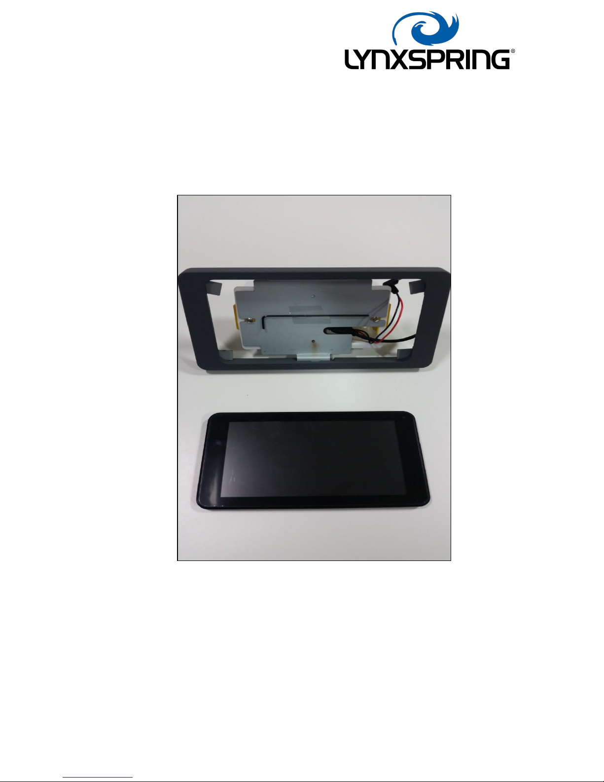
LYNX-WD-007-01 7” Display Assembly
Page 2
200SM071 v1.0 Page 2 of 4
Purpose
This document is provided to instruct a customer to install the Lynxspring Touch
Screen Display in as timely fashion as possible.
An inadequate, incomplete or inexistent install procedure may lead to the
incorrect operation of the equipment and/or the incorrect information being supplied
to the end user.
Scope
This document is intended for use by any competent person, with minimal IT skills
required. Do not attempt to install this product if you do not have the relevant skills &
experience to do so.
Procedure
The Lynxspring TSD is designed to be either mounted on a panel or in a standard
double gang back box, be it Flush, Surface or Dry-Lining. Ideally a 47mm deep box,
as this gives clear room for arranging the internals. The assembly, wherever fitted,
should have a form of isolation, such as a breaker in a panel or be fed from a
fused spur, previously installed. All wiring should be installed using standard
practices, by a competent person.
For power, it will require a single-phase feed of Live, Neutral & Earth (where
applicable). The Live & Neutral to be attached directly to the orange lever type
terminals supplied, (Live to Brown, Neutral to Blue) to be attached accordingly & the
earth connection to crimped and attached to the earthing stud on the Mount Plate.
This earthing combination is generally only required if wall / box mounting. It is
anticipated an alternative will be in place for panel mounting.
Please ensure the earth terminal is secured correctly.
If a wired Ethernet connection is the preferred communication method, then a
standard Cat5 cable should be supplied also, to be fed into the box & snap locked into
place at the open end of the Ethernet to USB adaptor.
Page 3

200SM071 v1.0 Page 3 of 4
Once wiring is complete, attached mounting plate.
Once plate attached, connect the microUSB cable to the matching socket & the 2.5mm
Barrel cable to the power socket, both located on the right had edge of the tablet.
Once both connections are in place (you will have to temporarily remove 2 of the
screen corner brackets and ease the tablet slightly out of the frame to give space to
slot the cables in), after re-attaching these brackets, locate the display frame assembly
over the top of the mount plate. There are grooves on the inside edge of the frame to
suit, long grooves on the top, small grooves & locking grub screw to the bottom.
Once in place, and ensuring no cable are dislodged or inadvertently crimped or
squashed, tighten the grub screw, using the Allan key supplied.
Installation is now complete. To power up the screen, insert the Allan key into the hole
in the frame on the right-hand side and press and hold until the display powers up,
evident by the screen showing 4 x penguins.
Finished Assy
Page 4

200SM071 v1.0 Page 4 of 4
Panel Mounting
The mounting plate is designed such that it allows both panel and box mounting. It is
supplied with a 1 to 1 printed template, which taped in place to your panel, with the
mounting hole points marked through onto your panel. It can then be removed and
the holes drilled. The hole sizes are annotated on the reverse of the template.
Once drilled, the mounting plate is attached using 2 x M3 x 6mm screws, with a NY
lock n
ut attached to each one for fixing. Once the plate is attached, the PSU can be
attached also, using a further 2 x M3 x 6mm screws & serrated washers, located and
tightened against the threaded clinch nuts, on the mounting plate, exposed by the free
holes. The supplied Grommet stripped is to be fitted to the inside of the 26mm hole
for protection. Once all attached, the connections can be made. The USB to Ethernet
converter can be attached to the back panel via cable ties or Velcro tape. A typical
wiring is show below. Once installed, follow the Setup Guide for operation.
 Loading...