

Page 1

JENEsys® Edge™ 534
1210 NE Windsor Drive
1 (877) 649-5969
© 2019 Lynxspring, Inc.
USER GUIDE
JENE-EG534
Lee’s Summit, MO 64086
sales@lynxspring.com
www.lynxspring.com
All Rights Reserved
Revised 2/1/2019
JENE-EG534-V2
Page 1 of 31
Page 2

JENEsys® Edge™ 534
1210 NE Windsor Drive
1 (877) 649-5969
© 2019 Lynxspring, Inc.
USER GUIDE
Trademarks
Onyxx® and the Onyxx logo are U.S. registered trademarks of Lynxspring, Inc.
Lynxspring™ and the Lynxspring logo are U.S. registered trademarks of Lynxspring, Inc.
JENEsys® Edge™ is a trademark of Lynxspring, Inc.
Other brands and product names mentioned in this manual may be trademarks or registered trademarks of their
respective companies and are hereby acknowledged.
Copyright Notice
© 2019 Lynxspring, Inc.
All rights reserved.
This document contains proprietary information which is protected by copyright. No part of this document may be
copied, photocopied, reproduced, translated, or converted to any electronic or machine-readable form in whole or
in part without prior written approval of Lynxspring, Inc.
Disclaimer
NO WARRANTY. This technical documentation is being delivered to you AS-IS, and Lynxspring makes no
warranty as to its accuracy or use. Any use of the technical documentation or the information contained therein is
at the risk of the user. Documentation may include technical or other inaccuracies or typographical errors.
Lynxspring reserves the right to make changes in this document without prior notice, and the reader should in all
cases consult Lynxspring to determine whether any such changes have been made. The information in this
publication does not represent a commitment on the part of Lynxspring.
Lynxspring shall not be liable for incidental or consequential damages resulting from the furnishing, performance,
or use of this material.
This guide contains links and references to third-party websites that are not under the control of Lynxspring, and
Lynxspring is not responsible for the content of any reference material or linked websites. If you access a third
party website mentioned in this guide, then you do so at your own risk. Lynxspring provides these links only as a
convenience, and the inclusion of the link does not imply that Lynxspring endorses or accepts any responsibility for
the content on those third-party sites.
Lynxspring, Inc.
1210 NE Windsor Drive
Lee’s Summit, MO 64086
P 816.347.3500 F 816.437.0780
http://www.lynxspring.com
Lee’s Summit, MO 64086
sales@lynxspring.com
www.lynxspring.com
All Rights Reserved
Revised 2/1/2019
JENE-EG534-V2
Page 2 of 31
Page 3

JENEsys® Edge™ 534
1210 NE Windsor Drive
1 (877) 649-5969
© 2019 Lynxspring, Inc.
USER GUIDE
Table of Contents
Niagara Documentation Addenda 4
JACE Start Up Addendum ...................................................................................................................................................................... 4
Platform Guide Addendum...................................................................................................................................................................... 5
JENEsys Edge 534 Startup procedure 6
Onyxx Network Quick Start 6
Configure the onyxxNetwork ................................................................................................................................................................... 6
Add an onyxxNetwork ........................................................................................................................................................................ 6
Discover and add Onyxx Devices ....................................................................................................................................................... 6
Manually adding Onyxx Devices ......................................................................................................................................................... 6
Add Onyxx Proxy points ......................................................................................................................................................................... 6
Using online Discover to add Onyxx Proxy points ............................................................................................................................... 7
Manually adding Onyxx Proxy points .................................................................................................................................................. 7
Onyxx Network Concepts 8
About Onyxx Network Architecture ......................................................................................................................................................... 8
About the Onyxx Network .................................................................................................................................................................. 8
Onyxx Network status notes .............................................................................................................................................................. 9
Onyxx Network monitor notes ............................................................................................................................................................ 9
Onyxx Network tuning policy notes .................................................................................................................................................. 10
Onyxx Network poll scheduler notes ................................................................................................................................................ 10
Onyxx Network views ...................................................................................................................................................................... 11
N Device Manager ................................................................................................................................................................................ 11
About the Onyxx Device ....................................................................................................................................................................... 12
Onyxx Device properties .................................................................................................................................................................. 12
Onyxx Point Manager ........................................................................................................................................................................... 13
Onyxx Driver Point Manager usage notes ......................................................................................................................................... 14
About Onyxx Driver Proxy points........................................................................................................................................................... 16
Onyxx Driver point types .................................................................................................................................................................. 16
Onyxx Driver Proxy Ext common properties ..................................................................................................................................... 17
Conversion types in Onyxx Driver Proxy points ................................................................................................................................. 18
Scale and offset calculation (linear) ................................................................................................................................................... 19
Non-linear sensor support ................................................................................................................................................................ 20
Linear Calibration Ext ....................................................................................................................................................................... 22
BooleanInputPoint ........................................................................................................................................................................... 23
BooleanOutputWritable .................................................................................................................................................................... 23
CounterInputPoint ............................................................................................................................................................................ 24
ResistiveInputPoint ........................................................................................................................................................................... 25
ThermistorInputPoint ........................................................................................................................................................................ 26
VoltageInputPoint ............................................................................................................................................................................. 29
VoltageOutputWritable ..................................................................................................................................................................... 29
About the Mini USB Port 29
Onyxx Network Driver Plugin Guides 29
Onyxx Network Driver Plugin Guides Summary ..................................................................................................................................... 29
N Device Manager ........................................................................................................................................................................... 30
Onyxx Driver Point Manager ............................................................................................................................................................. 30
Onyxx Network Troubleshooting 31
Lee’s Summit, MO 64086
sales@lynxspring.com
www.lynxspring.com
All Rights Reserved
Revised 2/1/2019
JENE-EG534-V2
Page 3 of 31
Page 4
JENEsys® Edge™ 534
1210 NE Windsor Drive
1 (877) 649-5969
© 2019 Lynxspring, Inc.
USER GUIDE
The following are addenda to Niagara Documentation: docJaceStartup and docPlatform
JACE Start Up Addendum
Please note the following amendments to Niagara Documentation “docJaceStartup” in regard to the operation of the
JENEsys Edge 534. Referenced Niagara documentation is included in the installation of ProBuilder™ or Niagara
Framework® and is typically located in a directory on the user’s PC, similar to: C:\JENEsys\JENEsys-3.8.111\docs
Pg. 3 - IP Address:
The JENEsys Edge 534 is shipped with a default address in the range of: 192.168.1.12n, like the JACE-3E,
JACE-6E, JACE-2/6 series.
Pg. 6 – Preparing to commission a new controller (Step 3):
Attach the cable to the primary Ethernet connector.
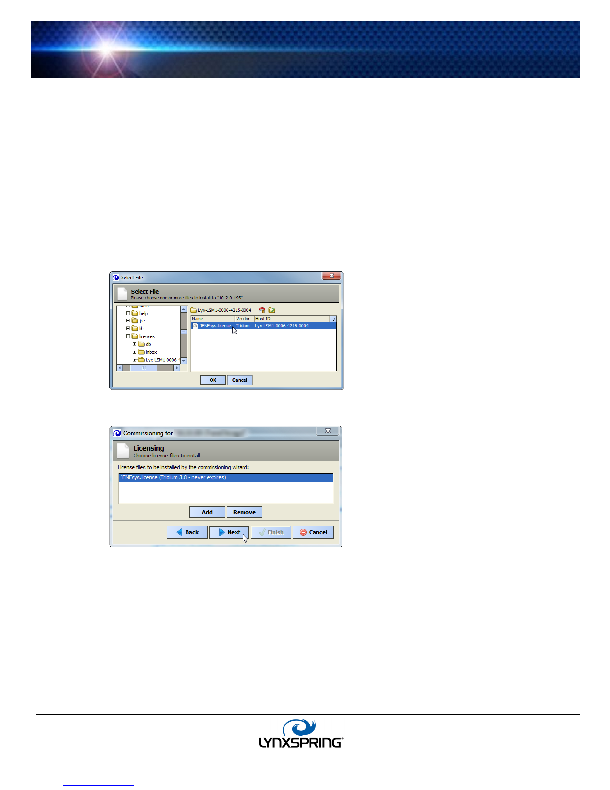
Pg. 14 - Starting the commissioning Wizard (Step 5):
Please refer to the screen below:
Pg. 15 - Starting the commissioning Wizard (Step 8):
Please refer to this screen below:
Pg. 46 - System Shell:
The JENEsys Edge 534 System Shell will be accessible using the Mini USB port, rather than an RS-232 port.
About the JACE System Shell Menu:
The Shell menu of the JENEsys-Edge 534 does not include the ability to enable/disable SFTP and
Telnet.
Pg. 50 - About serial shell mode - Items Needed for Serial System Shell:
An RS-232 port on your PC is not needed.
The JENEsys-Edge 534 will only require a Mini-USB to USB cable and terminal emulation software
installed on your PC.
The JENEsys-Edge 534 does not use a jumper.
Lee’s Summit, MO 64086
sales@lynxspring.com
www.lynxspring.com
All Rights Reserved
Revised 2/1/2019
JENE-EG534-V2
Page 4 of 31
Page 5

JENEsys® Edge™ 534
1210 NE Windsor Drive
1 (877) 649-5969
© 2019 Lynxspring, Inc.
Pg. 50 – 51 - Connecting to a serial system shell:
Set the Bits Per Second to 115200 for the JENEsys-Edge 534. (Step 5)
Steps 6 and 7 are not applicable to the JENEsys-Edge 534.
In Step 8, the movement of a jumper is not applicable to the JENEsys-Edge 534.
Platform Guide Addendum
Please note the following amendments to Niagara Documentation “docPlatform” in regards to the operation of the
JENEsys Edge 534:
Pg. 40 - Downgrading a JACE:
While there is a clean dist file for the JENEsys Edge 534 to restore it to a factory-like default, downgrading
beyond 3.8.111 is not available.
Pg. 41
1st Note:
The clean dist file for the JENEsys Edge 534 is only available on Lynxspring’s website.
2nd Note:
The JENEsys Edge 534 – AX is only available in builds 3.8.111 and 3.8.401, as of the date this
document was published.
Pg. 43 - Upgrading a JACE:
The JENEsys Edge 534 – AX can only be upgraded from 3.8.111 to 3.8.401. Lynxspring’s custom core files
and Onyxx drivers are required.
Pg. 47 - GPRS Modem Configuration:
The JENEsys Edge 534 does not support GPRS.
Pg. 95 - Wi-Fi Configuration:
At the time of publication of this document, the JENEsys Edge 534 does not support Wi-Fi.
Pg. 145 - Driver Types:
Some drivers are not supported by the JENEsys Edge 534.
USER GUIDE
Lee’s Summit, MO 64086
sales@lynxspring.com
www.lynxspring.com
All Rights Reserved
Revised 2/1/2019
JENE-EG534-V2
Page 5 of 31
Page 6

JENEsys® Edge™ 534
1210 NE Windsor Drive
1 (877) 649-5969
© 2019 Lynxspring, Inc.
USER GUIDE
JENEsys Edge 534 Startup procedure
The startup of the JENEsys Edge 534 – AX is a two-step process as follows:
1. Commissioning the controller with 3.8.111 or 3.8.401, installing the latest Onyxx Driver, and;
2. Updating the Onyxx system version
From your PC, use the Niagara Workbench 3.8.111 or 3.8.401 installed with the “installation tool” option (checkbox
“This instance of Workbench will be used as an installation tool”). This option allows you to install necessary core files onto the
controller.
Download the latest Onyxx Driver package from our website, which includes necessary Niagara core files, a cleanDist file,
onyxxDriver.jar, platOnyxx.jar, and instructions. Follow the instructions provided in the driver package to arrange the files
appropriately, then to commission the controller and update the Onyxx system version. A station with an Onyxx Network is
required to initiate the Onyxx system version update. See Onyxx Network Quick Start for details on how.
Onyxx Network Quick Start
This section provides a collection of procedures to use the onyxxDriver to make Onyxx Proxy Points, the station interface to
physical I/O points. As with other NiagaraAX drivers, you can do most configuration from special “manager” views and property
sheets using Workbench.
Configure the onyxxNetwork
To add and configure the onyxxNetwork, perform the following main tasks:
• Add an onyxxNetwork
• Discover and add Onyxx Devices
Add an onyxxNetwork
Use the following procedure to add an onyxxNetwork under the station’s Drivers container.
To add an onyxxNetwork in the station:
Step 1: Double-click the station’s Drivers container, to bring up the Driver Manager.
Step 2: Click the New button to bring up the New DeviceNetwork dialog.
Step 3: Select onyxxNetwork, ensure number to add is 1, and click OK. This brings up a dialog to name this
network.
Step 4: Click OK to add the onyxxNetwork to the station.
Discover and add Onyxx Devices
In the Onyxx Driver architecture, file directories act as “device-level” components.
To discover Onyxx Devices:
Step 1: Double-click the onyxxNetwork to access the Device Manager.
Step 2: Click the Discover button to launch an Onyxx Device Discovery job.
Step 3: When complete, discovered Onyxx Devices are displayed in the top pane in the “Discovered” table. The
bottom pane, labeled “Database,” is a table of Onyxx Devices that are currently mapped into the Niagara station.
The database will remain empty until a device is added.
Step 4: Click to highlight the discovered Onyxx Device(s) you wish to add, then click the Add button. The Add
dialog appears, in which you can accept all defaults (
Step 5: Click OK to add the Onyxx Device(s) to your station.
Figure 3-5).
Manually adding Onyxx Devices
Manually add Onyxx Devices, using the New button in the Device Manager.
Add Onyxx Proxy points
As with device objects in other drivers, each Onyxx Device has a Points extension that serves as the container for Proxy
points. The
This section provides quick start procedures for both tasks, as follows:
onyxxDriver Point Manager is used to create Onyxx Proxy points under any Onyxx Device.
Lee’s Summit, MO 64086
sales@lynxspring.com
www.lynxspring.com
All Rights Reserved
Revised 2/1/2019
JENE-EG534-V2
Page 6 of 31
Page 7

JENEsys® Edge™ 534
1210 NE Windsor Drive
1 (877) 649-5969
© 2019 Lynxspring, Inc.
• Using online Discover to add Onyxx Proxy points
• Manually adding Onyxx Proxy points
USER GUIDE
Using online Discover to add Onyxx Proxy points
This is the recommended way to accurately add Onyxx Proxy points under an Onyxx Device. Use the following
procedures:
• To discover I/O points
• To add discovered I/O points as Onyxx Proxy points
Note: If your onyxxNetwork has multiple Onyxx Devices, repeat both procedures (discover and add) for each
Device, until you have all I/O points proxied in the station.
To discover I/O points
Step 1: In the N Device Manager, in the Exts column, double-click the Points icon in the row representing the
Onyxx Device you wish to explore. This brings up its Onyxx Driver Point Manager.
Step 2: Click the Discover button to learn what I/O points are on the Onyxx Device. When the discovery job
completes, discovered I/O points are listed in the top pane of the view in the “Discovered” table. Each I/O point
occupies one row.
To add discovered I/O points as Onyxx Proxy points
Step 1: Select the I/O point or points in the Database pane of the Onyxx Driver Point Manager.
Step 2: You can map selected points in the station in different ways:
• Drag from the Discovered pane to the Database pane.
• Double-click an item in the Discovered pane.
• Right-click, then select add.
Note: All these actions will open up an “Add” dialog box.
Step 3: When the “Add” dialog appears, you typically edit a number of fields for each I/O point. For complete
details, see “Onyxx Driver Point Manager usage notes” on page 14.
The following brief summaries explain Add dialog fields:
• Name - This is the Onyxx Proxy point name—you typically change this to describe the I/O purpose.
• Type - This is the Onyxx “type,” which is selectable for any “universal input,” but fixed for any output. See
“Universal Input selection notes” on page 14 and “Output type selection notes” on page 15.
Note: Unlike other entries in the Add dialog, you cannot edit the point’s Type later.
• Address - This is the learned I/O point’s hardware’s port address.
• Poll Frequency - This specifies the point’s poll frequency group (default is Normal).
• Conversion - This specifies the conversion type used between the Onyxx Proxy extension’s “Device Facets”
and the parent point’s facets. See “Conversion types in Onyxx Driver Proxy points” on page 18.
• Facets - These are the Onyxx Proxy point’s facets, for how the value should be displayed in Niagara.
Step 4: When you have Onyxx Proxy point(s) configured properly, click OK. The Proxy points will be added to the
station and appear in the Database pane. For more details, see “About Onyxx Driver Proxy points” on page 16.
Note: In cases where you notice a fault status for input points you have edited with “non-default” facets, it is
likely related to a mismatch of the “Units” in the point’s automatically-appended Linear Calibration Ext. To clear
this fault status, expand the point’s Linear Calibration Ext and edit Units to match the units in the point’s
facets. For more information, see “Linear Calibration Ext” on page 22.
Manually adding Onyxx Proxy points
Manually add Onyxx Proxy points, using the “New” button in the Onyxx Point Manager, or by dragging from the Onyxx
palette. However, this method is generally not recommended as the path for the point will not be automatically populated.
Lee’s Summit, MO 64086
sales@lynxspring.com
www.lynxspring.com
All Rights Reserved
Revised 2/1/2019
JENE-EG534-V2
Page 7 of 31
Page 8
JENEsys® Edge™ 534
1210 NE Windsor Drive
1 (877) 649-5969
© 2019 Lynxspring, Inc.
USER GUIDE
Onyxx Network Concepts
This section provides conceptual details on the onyxxNetwork driver and its components, including views. onyxxNetwork Driver
components are the station interface to physical I/O points on JENEsys Edge 534 controllers and attachable I/O extender
modules.
About Onyxx Network Architecture
Essentially, the onyxxNetwork is similar in functionality to the NdioNetwork and uses the standard NiagaraAX network
architecture. For example, real-time data is modeled using Onyxx Proxy points, which resides under an Onyxx “device”
within an Onyxx network container in the station’s Driver Container (Drivers in Nav Tree). Hierarchically, the component
architecture is: network, device, point extension, points.
Figure 3-1 onyxxNetwork driver architecture
Similarly to Ndio, “Points” is the only extension under an Onyxx “device,” and the purpose of the onyxxDriver is to configure
(and Proxy) the actual I/O hardware points.
Note: Use “Manager” views of Onyxx container components to add all Onyxx components to your station, including
Proxy points. In these views, the driver provides online “discovery” of available devices and points and will
automatically populate path names for devices and points.
For more details see:
• About the Onyxx Network
• N Device Manager
• About the Onyxx Device
• Onyxx Driver Point Manager
• About Onyxx Driver Proxy points
About the Onyxx Network
The onyxxNetwork is the top-level container component for “everything Onyxx” in a station.
Note: Only one onyxxNetwork component is valid in a station, regardless of how many Onyxx XM 34IOs or Onyxx XM
34IO-Bs are present.
The onyxxNetwork should reside in the station’s Driver Container. Add an onyxxNetwork from the Driver Device Manager
view, using the “New” command.
Lee’s Summit, MO 64086
sales@lynxspring.com
www.lynxspring.com
All Rights Reserved
Revised 2/1/2019
JENE-EG534-V2
Page 8 of 31
Page 9
JENEsys® Edge™ 534
1210 NE Windsor Drive
1 (877) 649-5969
© 2019 Lynxspring, Inc.
Figure 3-2 onyxxNetwork driver architecture
USER GUIDE
Note: The JENEsys Edge 534 must have the Onyxx module installed.
The onyxxNetwork component has the typical collection of slots and properties as most other network components. The
following sections explain further:
• Onyxx Network status notes
• Onyxx Network monitor notes
• Onyxx Network tuning policy notes
• Onyxx Network poll scheduler notes
• Onyxx Network views
Onyxx Network status notes
Unlike most “fieldbus” drivers such as BACnet and Lonworks, the status of an onyxxNetwork can be “down,” in
addition to the normal “ok” or less typical “fault”. A down status might occur in the case of external I/O where the
physical connection was removed (no communications are possible), or no Onyxx devices were added to the
database.
The Health slot contains historical timestamp properties that record the last network status transitions from “ok” to any
other status. The “Fault Cause” property further explains any fault status.
Note: As in other driver networks, the onyxxNetwork has an available “Alarm Source Info” container slot you can
use to differentiate onyxxNetwork alarms from other component alarms in the station. See “About network Alarm
Source Info” in the Drivers Guide for more details.
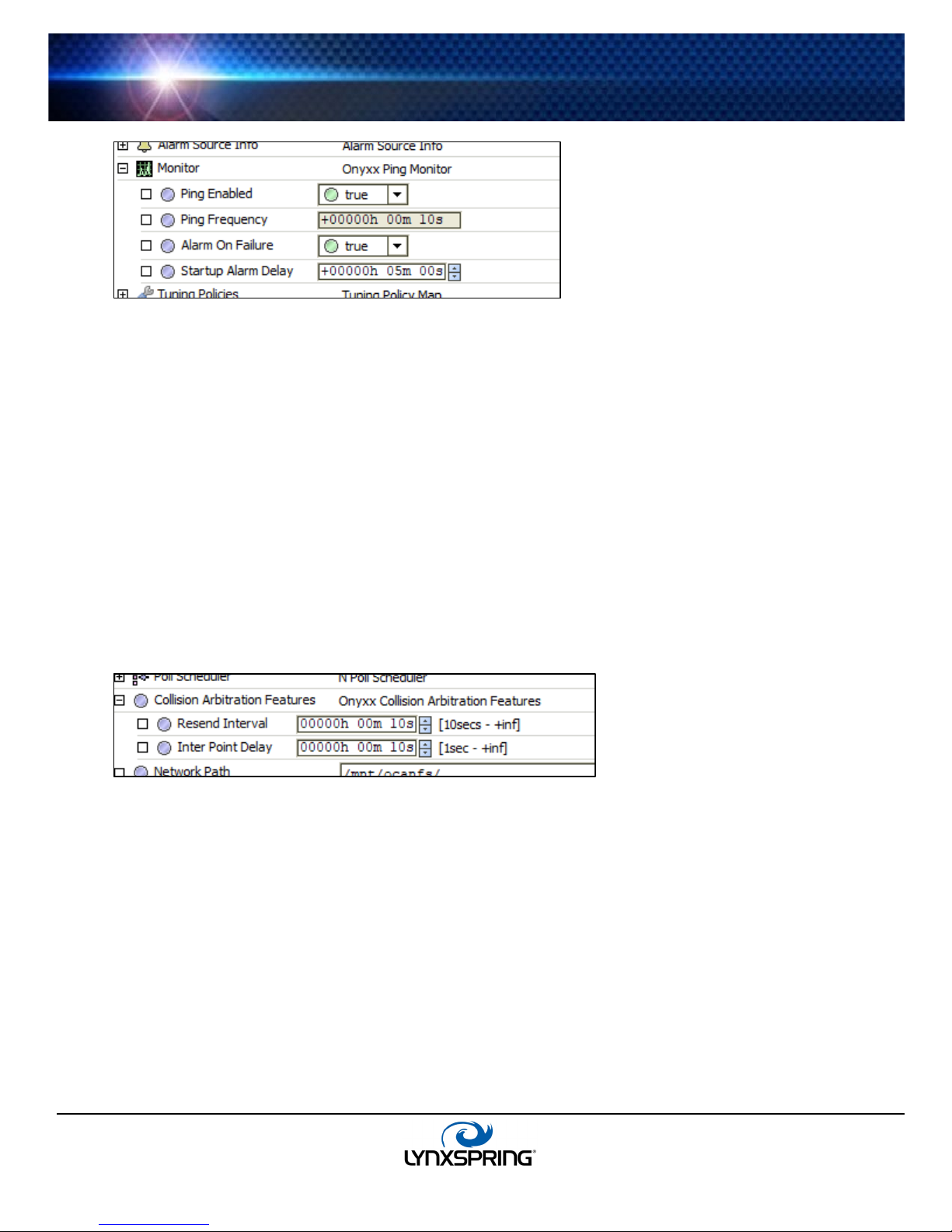
Onyxx Network monitor notes
The Onyxx Network monitor ( Onyxx Ping Monitor)contains the basic network monitoring properties. For general
information, see “About Monitor” in the Drivers Guide. This monitor is set to run every 10 seconds and is not editable.
Lee’s Summit, MO 64086
sales@lynxspring.com
www.lynxspring.com
All Rights Reserved
Revised 2/1/2019
JENE-EG534-V2
Page 9 of 31
Page 10
JENEsys® Edge™ 534
1210 NE Windsor Drive
1 (877) 649-5969
© 2019 Lynxspring, Inc.
Figure 3-3 Monitor properties of onyxxNetwork
USER GUIDE
Onyxx Network tuning policy notes
The onyxxNetwork has the typical network-level Tuning Policy Map slot with a single default Tuning Policy. More
information for this can be found in the “About Tuning Policies” in the Drivers Guide. However, given the small number
of total Onyxx Proxy points supported under an onyxxNetwork, the importance of creating additional tuning policies (or
editing the default tuning policy) is generally lower, relative to other driver networks.
Onyxx Network poll scheduler notes
The onyxxNetwork has the typical network-level Poll Scheduler slot with standard collection of properties, as described
in “About poll components” in the Drivers Guide. The following notes apply to the Poll Scheduler of an onyxxNetwork:
• By default, discovered/added Onyxx Proxy points have a Poll Frequency setting of “Normal” at the default Normal
Rate of 5 seconds. Given the small number of total Onyxx Proxy points supported under an onyxxNetwork, you
can safely assign them to the “Fast” rate (default 1 second).
• The Poll Frequencies of Fast, Normal, and Slow can be increased or decreased as desired.
Collision Arbitration Features
The Onyxx Network relies on values to be sent regularly across the sub-network as a stream. The reciever actively
“listens” for messages that pertain to it. In case the receiver was busy when the original message was sent, two
properties were added to allow for correcting – ‘Resend Interval’ and ‘Inter Point Delay.’
Resend Interval
This property allows the time between needed repeated messages to be increased or decreased. It defaults to
10 seconds (minimum) and has no upper limit. Increasing it may help minimize collisions.
Inter Point Delay
Due to the nature of the receiver, sending multiple messages at nearly the same time can cause messages to
not be received, as the receiver will be busy. This property decreases the speed at which the re-sent
messages for the same receiver are produced. The default is set for 10 seconds and can be lowered to 1
second.
Oversample Tuning
This property allows users to specify the sampling rate for collecting values. In general, values are calculated by
taking x samples of the value across a time period. The value is then calculated by averaging all the values within
the timeperiod. The more number of samples, the less an outlier will affect the value. However, this also increases
the burden on the CPU. This property is set at its max (255) so as to calculate the best value. If performance is a
concern, users can set this value lower. Though, this can allow outliers to skew the calculated value in the outliers’
direction.
Lee’s Summit, MO 64086
sales@lynxspring.com
www.lynxspring.com
All Rights Reserved
Revised 2/1/2019
JENE-EG534-V2
Page 10 of 31
Page 11

JENEsys® Edge™ 534
1210 NE Windsor Drive
1 (877) 649-5969
© 2019 Lynxspring, Inc.
USER GUIDE
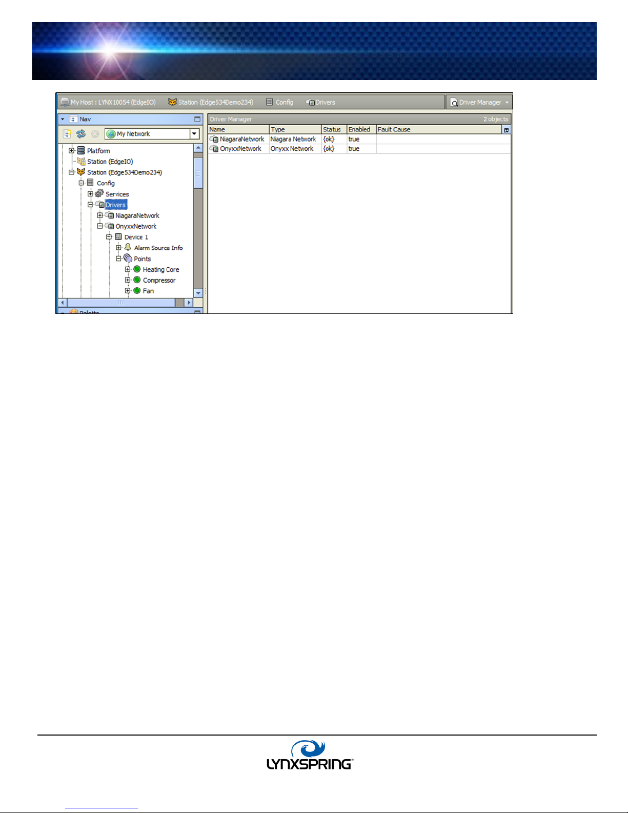
Onyxx Network views
The default view of the onyxxNetwork is the ‘N Device Manager.’ This is the equivalent of the ‘Device Manager’ in most
other drivers. Use this view to discover and add Onyxx Device components to the station. For details, see
“N Device Manager” below. Other standard views are also available on the onyxxNetwork.
N Device Manager
As the default onyxxNetwork view, the ‘N Driver Device Manager’ view can be used to discover and add one or more
“device-level” Onyxx Device components to the station’s database (
“About the Device Manager” in the Drivers Guide.
Figure 3-4 Adding Onyxx Device discovered using N Device Manager
Figure 3-4). For general information, refer to
Figure 3-5 Add dialog for Onyxx Device(s)
Onyxx Board Manager Usage notes
Before launching a discover job, ensure that any external I/O modules are correctly installed and connected to
the host JENEsys Edge 534 controller. When adding the device to the database, changes to any defaults
other than “Name” is not needed (
Figure 3-5).
Lee’s Summit, MO 64086
sales@lynxspring.com
www.lynxspring.com
All Rights Reserved
Revised 2/1/2019
JENE-EG534-V2
Page 11 of 31
Page 12

JENEsys® Edge™ 534
1210 NE Windsor Drive
1 (877) 649-5969
© 2019 Lynxspring, Inc.
USER GUIDE
About the Onyxx Device
The Onyxx Device represents an I/O-34 board and can be extended by attaching Onyxx XM modules. The JENEsys Edge
534 and Onyxx XM modules hold the processors that allow for servicing hardware I/O points.
Figure 3-6 Onyxx Device property sheet
Under an onyxxNetwork, each Onyxx Device must have a unique “Device Path.” Apart from the “Enabled” property, this is
the only writable property of an Onyxx Device. All other Onyxx properties are read-only types (
status and I/O capabilities.
Figure 3-6), reflecting the
Note: The N Device Manager view of the onyxxNetwork provides online discover and add commands to ensure all
available Onyxx Devices can be created and configured properly.
Each Onyxx Device has a single important device extension named Points. This is the container for all of a device’s Proxy
points. Each Proxy point represents a specific I/O terminal address on the device (JENEsys Edge 534 or Onyxx XM 34IO),
serviced by that board’s I/O processor(s). For more details, see “Onyxx Point Manager” on page 13.
Onyxx Device properties
Onyxx Device properties can be categorized into two groups:
1. Device status properties
2. Config properties
Note: As in other driver networks, the Onyxx Device has an available “Alarm Source Info” container slot you can use to
differentiate Onyxx Device alarms from other component alarms in the station.
1. Device status properties
Onyxx Devices have typical device-level status properties:
• Status - Status of the onyxxNetwork communications to this Onyxx Device; possible status flags include:
Ok - Normal communications, no other status flags
Disabled - Enabled property is set to false, either directly or in onyxxNetwork and while status is disabled,
all child onyxxPoints have disabled status; Onyxx Device polling is suspended
Fault - Typically configuration error, e.g. Onyxx Device (duplicate or invalid IO Port number)
Down - Error communicating to one or more Onyxx I/O processors on Onyxx XM 34IO
• Enabled - Either true (default) or false; can be set directly or in the parent onyxxNetwork; see Status disabled
description above
• Fault Cause - Describes the cause of a fault
• Health - Contains properties, including timestamps of last “ok” time and last “fail” time, and a string property
describing the last fail cause
Lee’s Summit, MO 64086
sales@lynxspring.com
www.lynxspring.com
All Rights Reserved
Revised 2/1/2019
JENE-EG534-V2
Page 12 of 31
Page 13

JENEsys® Edge™ 534
1210 NE Windsor Drive
1 (877) 649-5969
© 2019 Lynxspring, Inc.
USER GUIDE
2. Config properties
In addition to common device-level status properties, an Onyxx Device has the following additional properties.
• Device Path – Set automatically if the device was discovered and added; a sub-portion of the full directory path
• Led Firmware Version – Displays the current firmware version of the chip that controls the LED board
• Analog Ouput Firmware Version – Displays the current firmware version of the chip that controls the AO Ports
• Digital Output Firmware Version – Displays the current firmware version of the chip that controls the DO ports
• Univesal Input Firmware Version_Lower Ports – Displays the current firmware version of the chip that controls
the UI 1-8 ports
• Universal Input Firmware Version_Upper Ports – Displays the current firmware version of the chip that controls
the UI 9-16 ports
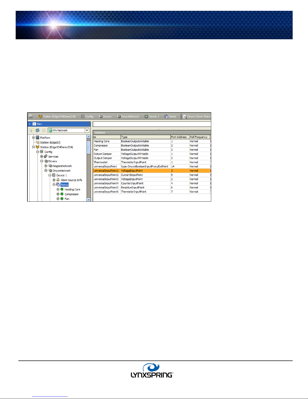
Onyxx Point Manager
As the default view for the Points extension under an Onyxx Device, the onyxxDriver Point Manager allows available I/O
terminal “points” to be discovered and add corresponding Onyxx Proxy points added to the station database.
Figure 3-7 Adding Onyxx Proxy points discovered using Onyxx Driver Point Manager
A Proxy point is added for each discovered I/O terminal. For more details, see “Onyxx Board Manager Usage notes” on
page 11. For procedures, see “Add Onyxx Proxy points” on page 6.
Lee’s Summit, MO 64086
sales@lynxspring.com
www.lynxspring.com
All Rights Reserved
Revised 2/1/2019
JENE-EG534-V2
Page 13 of 31
Page 14

JENEsys® Edge™ 534
1210 NE Windsor Drive
1 (877) 649-5969
© 2019 Lynxspring, Inc.
Onyxx Driver Point Manager usage notes
The following notes apply when using the Onyxx Driver Point Manager:
• Add and Edit dialog fields
• Universal Input type selection notes
• Output type selection notes
Add and Edit dialog fields
When adding Onyxx Proxy points for discovered I/O points, the following items are available in the Add dialog
Figure 3-8)
(
Figure 3-8 Add dialog in Onyxx Driver Point Manager
USER GUIDE
• Name - Name of the Onyxx Proxy point; can be edited from the default name to reflect the actual purpose
of the I/O point, such as “Room101T,” “AHU-1_FanStatus,” and so forth
Note: The number appended onto a default name has no association to the I/O point address.
• Type - The type of Onyxx Proxy point to create (cannot be edited after adding it to the database, see
“Universal Input selection notes” below)
• Port Address - The I/O terminal address within that general IO type; recommended to be left at defualt
value
• Poll Frequency - The assigned poll frequency group, as configured in the Onyxx Network’s poll
scheduler; see “Onyxx Network poll scheduler notes” on page 10
• Conversion - The conversion type used between units in the Proxy extension’s “Device Facets” and the
units in the parent point’s Facets; see “Onyxx Driver Proxy Ext common properties” on page 17 for more
details
• Point Type - Closely related to the “Type” field; specifies if point will be a Current, Resistance, or Voltage
point
• Facets - Facets for the Onyxx Proxy point and equivalent to accessing facets through the point’s property
sheet; automatically set during creation
Universal Input selection notes
All JENEsys Edge 534 controllers and Onyxx XM 34IO controllers external I/O modules provide 16 “universal
inputs” (UI) terminals. On the device, these terminals are labeled UI1 to UI6.
The default Point Type is VoltageInputPoint and can be changed before adding to the database, as shown in
Figure 3-9.
Lee’s Summit, MO 64086
sales@lynxspring.com
www.lynxspring.com
All Rights Reserved
Revised 2/1/2019
JENE-EG534-V2
Page 14 of 31
Page 15

JENEsys® Edge™ 534
1210 NE Windsor Drive
1 (877) 649-5969
© 2019 Lynxspring, Inc.
Figure 3-9 Select Onyxx Driver input type for each universal input
USER GUIDE
For most I/O platforms, any of the following are valid universal input choices:
• VoltageInputPoint - NumericPoint that reads a 0-to-10Vdc input signal and produces either a voltage
value or linear scaled output value
• ResistiveInputPoint - NumericPoint that reads a resistive signal within a 0-to-100K ohm range and
produces either an ohms value or linear scaled output value
• ThermistorInputPoint - NumericPoint that reads a Thermistor temperature sensor (Type 3, or other) signal
and produces a scaled output value
• CurrentInputPoint - NumericPoint that reads 4mA to 20mA and produces an amperage value
• CounterInputPoint - NumericPoint that counts the number of contact closures at the input
• BooleanInputResistive - BooleanPoint that reads the resistive input as one of two boolean states
(equipment status); if the measured resistance level becomes higher than the threshold level, the point will
output false
• BooleanInputVoltage - BooleanPoint that reads the voltage input as one of two boolean states
(equipment status); if the measured resistance level becomes higher than the threshold level, the point will
output true
• BooleanInputCurrent - BooleanPoint that reads the current input as one of two boolean states
(equipment status); if the measured resistance level becomes higher than the threshold level, the point will
output true
Selecting any Type other than Boolean creates a standard NumericPoint, with a specified OnyxxInputProxy
extension. Selecting BooleanInputPoint creates selections result in a BooleanPoint with an
OnyxxBooleanInputProxy extension. For more details, see “About Onyxx Driver Proxy points” on page 16.
Note: After adding an Onyxx Proxy point, the name, port address, conversion, and facets are all editable; type
is not. To change type, the point must be deleted and added again, selecting from the Type drop-down
menu, as shown in
Figure 3-9. The ResistiveInputPoint and ThermistorInputPoint are identical, except for the
conversion type used in the ProxyExt.
Output type selection notes
JENEsys Edge 534 devices and Onyxx extender modules have 10 digital outputs (DO) and 8 analog Output (AO)
terminals. For any discovered output I/O terminal, the Add dialog preselects the appropriate writable OnyxxPoint
type, as either:
• BooleanOutputWritable: A standard BooleanWritable point, with an OnyxxBooleanOutput Proxy
extension
• VoltageOutputWritable: A standard NumericWritable point, with an OnyxxVoltageOutput Proxy extension
Lee’s Summit, MO 64086
sales@lynxspring.com
www.lynxspring.com
All Rights Reserved
Revised 2/1/2019
JENE-EG534-V2
Page 15 of 31
Page 16

JENEsys® Edge™ 534
1210 NE Windsor Drive
1 (877) 649-5969
© 2019 Lynxspring, Inc.
USER GUIDE
About Onyxx Driver Proxy points
Onyxx Proxy points are similar to Proxy points in other drivers. Alarm and history extensions can be added to them, and
they can be linked to other station logic.
The following sections explain further:
• Onyxx Driver point types
• Onyxx Driver Proxy Ext common properties
• Conversion types in Onyxx Driver Proxy points
• Scale and offset calculation (linear)
• Non-linear sensor support (AX-3.4 and later)
• Linear Calibration Ext
Onyxx Driver point types
As seen in the onyxxDriver palette (Figure 3-10), there are 7 different onyxxDriver point types.
Figure 3-10 Onyxx Driver components as seen in the onyxxDriver palette
These 7 different onyxxDriver point types derive from the following 4 control point types:
• BooleanPoint - For Boolean “universal input” types; can be used to create BooleanInputPoint–Resistive point
type
• NumericPoint - For Numeric “universal input” types; can be used to create CounterInputPoints,
ResistiveInputPoints, ThermistorInputPoints (using ResistiveInputPoints and modifying), VoltageInputPoints,
and CurrentInputPoints
• BooleanWritable - For Boolean output types; can be used to create BooleanOutputWritable Points
• NumericWritable - For numeric output types; can be used to create VoltageOutputWritable Points
Each onyxxDriver point type is typically unique by one or more properties in its Proxy extension. Also, the Proxy
extension in each type contains the same (common) properties. Things unique to each
explained in following sections, as well as common properties in each point’s Proxy extension.
Lee’s Summit, MO 64086
sales@lynxspring.com
www.lynxspring.com
onyxxDriver point types are
All Rights Reserved
Revised 2/1/2019
JENE-EG534-V2
Page 16 of 31
Page 17

JENEsys® Edge™ 534
1210 NE Windsor Drive
1 (877) 649-5969
© 2019 Lynxspring, Inc.
Onyxx Driver Proxy Ext common properties
Figure 3-11 Common properties among Onyxx Proxy extensions
USER GUIDE
As shown in the property sheet view (Figure 3-11), each onyxxDriver point has the following properties in its Proxy
extension (Proxy Ext):
• Status - (read only) Status of the Proxy extension
• Fault Cause - (read only) Provides a text description of why the point status is in fault
• Enabled - True (default) or false; when set to false, the point’s status becomes disabled and onyxxDriver
polling is suspended
• Device Facets - (read only) Native facets used in Proxy read or writes (Parent point’s facets are used in point
status display, and are available for edit in Add and Edit dialogs in Point Manager)
• Conversion – Specifies the conversion used between the “read value” (in Device Facets) and the Parent
point’s output (in selected point facets); see “Conversion types in Onyxx Driver Proxy points” on page 18 for
more
• Tuning Policy Name – The assigned tuning policy, which is typically “Default Policy”
• Read Value - (read only) The last value read, using device facets
• Write Value - (read only) For writable point, this is the last value written, using device facets
• Point Type - (read only) Such as “BooleanResistiveInput,” “ResistiveInput,” “BooleanOutput”
• Port Address - The point’s I/O terminal address for its hardware type (UI, AO, DO), automatically found during
discovery; if port address is out of range or a duplicate (within the same board), the point has a fault status
• Poll Frequency - The assigned poll frequency group -- either Slow, Normal (default), or Fast
• Raw - (read only) The integer value returned from the onyxxDriver processor
• Hysteresis (hidden) – Averages the output value to reduce signal bounces
• Hysteresis Size (hidden) – Specifies the number of samples to average into the calculated output value
Lee’s Summit, MO 64086
sales@lynxspring.com
www.lynxspring.com
All Rights Reserved
Revised 2/1/2019
JENE-EG534-V2
Page 17 of 31
Page 18

JENEsys® Edge™ 534
1210 NE Windsor Drive
1 (877) 649-5969
© 2019 Lynxspring, Inc.
Conversion types in Onyxx Driver Proxy points
In any onyxxDriver Proxy point. a Conversion property is available with the following selections:
Note: Currently, Workbench provides no filtering of Conversion types based on the Onyxx Proxy point being
configured. You will see the same Conversion drop-down selection list for a VoltageInputPoint as you do for a
BooleanOutputWritable. However, only a few combinations are typically useful. In addition, there may be
conversion types included that are not applicable, such as “Sm2 Flow Conversion,” which can be ignored.
500 Ohm Shunt
Applies only to a VoltageInputPoint used to read a 4-to-20mA sensor, where the UI input requires a 500 ohm
resistor wired across (shunting) the input terminals. The input signal is 2V to 10V. If this conversion type is not
available, select Linear conversion instead.
As compared to a Linear or Generic Tabular conversion, this selection provides better resolution near the upper
(20mA/10V) range of the input, compensating for input clamping protection the circuitry automatically applies
when input voltage rises above 3.9V.
Note: Currently, selection of 500 Ohm Shunt produces a “secondary” selection for conversion type, with all
conversion types shown again. Typically, only the Linear type is valid, providing the 4-20mA sensor has a
linear response. In the Scale and Offset fields for this Linear conversion, you enter whatever calculated values
are needed to display in the appropriate units of measurement for that sensor.
configuration of such a point.
Figure 3-12 Example VoltageInputPoint used for 4-to-20mA input (Edit dialog from Point Manager)
USER GUIDE
Figure 3-12 shows an example
For background on this example configuration, see “Scale and offset calculation example 2”.
In the unusual case of a non-linear 4-20mA sensor, the secondary conversion type “Generic Tabular” can be used.
Default
(The default selection)
Conversion between “similar units” is automatically performed within the Proxy point. For example, if the “units”
facets of a
value, from degrees C.
If you set the Parent point’s facets to dissimilar units (often the case with a VoltageInputPoint), the parent point
has a fault status to indicate a configuration error. In this case, you must select Linear conversion, and also set
“Units” in the point’s “LinearCalibrationExt” to match the point’s facets. See “Scale and offset calculation (linear)”
on page 19 and “Linear Calibration Ext” on page 22.
ThermistorInputPoint is set to degrees F, the point output automatically converts to the appropriate
Generic Tabular
This Conversion type allows nonlinear support for devices other than for thermistor temperature sensors with units
in temperature. Generic Tabular uses a “lookup table” method similar to the “Thermistor Tabular” conversion, but
without predefined output units. Selection provides a popup
“source-to-result” non-linear curve is entered, including the ability to import and export response curve files. For
more details, see “Non-linear sensor support” on page 20 and “Curve File Import/Export notes” on page 28.
Tabular Conversion Dialog in which a custom
Lee’s Summit, MO 64086
sales@lynxspring.com
www.lynxspring.com
All Rights Reserved
Revised 2/1/2019
JENE-EG534-V2
Page 18 of 31
Page 19

JENEsys® Edge™ 534
1210 NE Windsor Drive
1 (877) 649-5969
© 2019 Lynxspring, Inc.
Linear
Applies to VoltageInputPoint, ResistiveInputPoint, and VoltageOutputWritable points. Typically, the point’s
output value is set to a unit of measurement other than Device Facets (voltage or resistance). The Linear selection
provides two fields to make the transition:
• Scale: Determines linear response slope.
• Offset: Offset used in output calculation.
For related details, see “Scale and offset calculation (linear)” on page 19.
Note: For a VoltageInputPoint used for a 4-to-20mA sensor (shunt resistor on UI input), another primary
conversion type should be used, if available: 500 Ohm Shunt, with Linear typically selected as the “secondary”
conversion. See more about that other conversion type above.
Reverse Polarity
Useful in a BooleanInputPoint or BooleanOutputWritable to reverse the logic of the hardware binary input or
output.
Note: Be careful in the use of the reverse polarity conversion, as it may lead to later confusion when
troubleshooting logic or communications problems.
Thermistor Type 3
Applies to a ThermistorInputPoint, where this selection provides a “built-in” input resistance-to-temperature value
response curve for Type 3 Thermistor temperature sensors.
Tabular Thermistor
Applies to a ThermistorInputPoint, where this selection provides a control for a popup dialog for a custom
resistance-to-temperature value response curve, including ability to import and export curve response files. For
more details, see “Tabular Thermistor notes” on page 26 and “Curve File Import/Export notes” on page 28.
Scale and offset calculation (linear)
Unless you want a VoltageInputPoint or VoltageOutputWritable to operate with facets (units) of volts, you must set
the point’s facets to the desired units, and set the ProxyExt Conversion property to Linear.
You must then enter your calculated scale and offset values in the Linear fields. Also, you must set the
“Units” in its Linear Calibration Ext to match an input point’s facets—otherwise a fault status occurs.
Note: This also applies to any linearly-responding ResistiveInputPoint using point facets other than ohms.
Use the following formulas to calculate the Linear scale and offset values:
Where: x1 and x2 are the values (e.g. voltage), and y1 and y2 are the corresponding desired units.
• Scale
Scale = (y2 - y1) / (x2 - x1)
• Offset
Offset = y1 - (Scale * x1)
See example 1 and example 2.
Scale and off set calculation… Example 1
You have a 6-to-9Vdc actuator to control with a VoltageOutputWritable, in terms of 0-to-100% input.
Configure this point’s facets to have units: “misc,” “percent” (%).
Set the ProxyExt’s Conversion property to Linear, and enter these calculated scale and offset values:
• Scale
Scale = (y2 - y1) / (x2 - x1)
Scale = (100% - 0%) / (9V - 6V) = 100/3 = 33.3333333
• Offset
Offset = y1 - (Scale * x1)
Offset = 0% - (33.3333333 * 6V) = 0 - 200 = -200
USER GUIDE
Lee’s Summit, MO 64086
sales@lynxspring.com
www.lynxspring.com
All Rights Reserved
Revised 2/1/2019
JENE-EG534-V2
Page 19 of 31
Page 20

JENEsys® Edge™ 534
1210 NE Windsor Drive
1 (877) 649-5969
© 2019 Lynxspring, Inc.
Scale and offset calculation… Example 2
You have a linear 4-to-20mA differential pressure sensor to read with a VoltageInputPoint (using an external 500
ohm resistor wired across the input), reading effectively 2V to 10V. The range of this sensor is from -10in.wc. to
+10in.wc. Configure this point’s facets to have units: “pressure,” “in/wc”.
Set the ProxyExt’s Conversion property to use “500 Ohm Shunt” (if available), then “Linear” as secondary, and in
the Linear fields enter these calculated scale and offset values:
• Scale
• Offset
Figure 3-12 shows this point’s configuration in a Workbench dialog. Note that the Linear Calibration Ext for this
point will require its “Units” property to be configured to match the facets for this point - otherwise, the point will
have a fault status. See the “Linear Calibration Ext” section for related details.
Non-linear sensor support
The conversion selection Generic Tabular provides a way for a VoltageInputPoint or ResistiveInputPoint to support a
nonlinear signal on a universal input (using point Facets other than temperature). Note that the
also provides non-linear support for resistance-based temperature sensors, but point Facets are limited to
temperature.
If you select Conversion type of “Generic Tabular” an edit control (note pad icon) appears in the property sheet beside
it. Click the icon to see the Tabular Conversion Dialog, as shown in
Figure 3-13 Tabular Conversion Dialog from edit control
USER GUIDE
Scale = (y2 - y1) / (x2 - x1)
Scale = (+10in.wc - -10in.wc) / (10V - 2V) = 20/8 = 2.5
Offset = y1 - (Scale * x1)
Offset = -10in.wc - (2.5 * 2V) = -10 - 5 = -15
ThermistorInputPoint
Figure 3-13.
Lee’s Summit, MO 64086
sales@lynxspring.com
www.lynxspring.com
All Rights Reserved
Revised 2/1/2019
JENE-EG534-V2
Page 20 of 31
Page 21

JENEsys® Edge™ 534
1210 NE Windsor Drive
1 (877) 649-5969
© 2019 Lynxspring, Inc.
3000
800
10200
100
3200
700
10900
90
3500
600
11600
80
4000
500
12400
70
4200
450
13300
60
4600
400
14400
50
5000
350
15800
40
5500
300
17700
30
6100
250
20300
20
6900
200
30000
0
8200
150
This dialog allows you to edit the current “source-to-results” non-linear curve used by the Proxy point, import another
curve (.xml file), or export (save) the current curve as an .xml file. In this way you can provide any custom non-linear
curve needed.
The following notes apply to using this feature:
• A curve requires at least 2 points (rows), each using “Source” to “Results” values.
• Points are used in ascending order, by the Source column.
• Add as many points as is needed. There is no hard-coded limit. Click the Add button to add a new row for a
• If a point is skipped, it can be added at the end. When finished, click Resort. This automatically reorders all
• Click the delete icon (trash can) beside any point to delete it from the curve. If the Delete All button is clicked,
• Description text appears in the ProxyExt property sheet, beside the Conversion edit icon.
• When Save is clicked, the curve configuration is stored as part of the conversion object in the station (there is
Non-linear sensor example
You have a photo resistor-based illuminance sensor that measures light output from 0 to 800 lux, supplying a
resistance of 30K ohms to 3K ohms. Using a
and click the edit control for the Tabular Conversion Dialog (see
In the dialog, enter the sensor’s non-linear response curve (shown below). Configure this point’s facets to have
units: “illuminance,” “lux” (lx), and the same units in the point’s Linear Calibration Ext.
Table 3-1 Example illuminance sensor source (ohms) to results (lux)
Figure 3-13 shows a point with a non-linear curve described in the “Non-linear sensor example” below.
Source values use the “Device Facets” of the Onyxx Proxy point, and must be in the range of the
controller input. Therefore, if a
ResistanceInputPoint, source values must be between 0 to 100000 (Ohms).
Result values are typically the measured value, regardless of units, at each source point. This assumes no
further scaling using a LinearCalibrationExt—i.e., its Scale property is the default “1”.
point.
points in ascending order, by the Source column.
all points (plus any Description text) is removed (typically, this is done only to enter a new non-linear curve).
no association with any external file, in case you imported a non-linear curve).
Note: If you update a non-linear curve (say, add a point) after it was imported in one or more OnyxxPoints,
you need to export it (save) and re-import it in other points, in order for them to be updated.
Ohms Lux
Ohms Lux
VoltageInputPoint, source values must be between 0V to 10V, or if a
ResistiveInputPoint, select the conversion type Generic Tabular,
Figure 3-13 on page 20).
USER GUIDE
Lee’s Summit, MO 64086
sales@lynxspring.com
www.lynxspring.com
All Rights Reserved
Revised 2/1/2019
JENE-EG534-V2
Page 21 of 31
Page 22

JENEsys® Edge™ 534
1210 NE Windsor Drive
1 (877) 649-5969
© 2019 Lynxspring, Inc.
Linear Calibration Ext
By default, three of the UI-type OnyxxPoints (ResistiveInputPoint, ThermistorInputPoint, VoltageInputPoint) include
a “linearCalibration” slot containing 4 properties, as shown in
Figure 3-14 Linear Calibration Extension
USER GUIDE
Figure 3-14.
These properties allow you to “calibrate” the calculated value before it is applied to the Out slot, where:
[(calculatedValue x Scale) + Offset] = Out value.
Usage is optional, although Offset and Units are commonly configured.
Note: In most cases where the parent Onyxx Proxy point’s facets have been edited from defaults, note you must
edit the Units value in the Linear Calibration Ext to match the units in the point facets, otherwise the parent Proxy
point will have a fault status!
Typically, you see this fault status immediately after you add a new input point, for example a VoltageInputPoint or
ResistiveInputPoint, and configure it with a Linear conversion type (including a scale and offset), and then specify
the point’s facets. It may not be immediately clear that the problem is in this Linear Calibration Ext, where you
must match its Units value to the units in the point’s facets.
• Scale - Default is 1.0. Typically, you leave this at default. One exception is if you copied the
LinearCalibrationExt under a
• Offset - Default is 0.0. Can be either a positive or negative value, as needed. Often, this is useful to
compensate for signal errors introduced by sensor wiring resistance.
• Units - Set this to the same units as in the parent Proxy point’s facets (see Note: above).
• Fault Cause - Available in AX-3.2 and later. Provides a reason whenever this extension causes the parent
Proxy point to be in fault, e.g.: Units between point and extension are not convertible.
CounterInputPoint, in order to get a scaled total.
Note: You can also copy the linearCalibration extension without error to other OnyxxPoints based on Numeric
points. For example, a
CounterInputPoint where a “scaled total” out value is desired. Consider a
CounterInputPoint for a flow rate meter that provides a contact closure for every 0.15 gallons, configured as:
• Facets: gallons [units: volume (m^3), gallon (gal)]
• OynxxCounterInputProxyExt:
Conversion: Default
Output Select: Count
Rate Calc Type: FixedWindowRateType
Rate Calc:
Scale: 9.0
Interval: 15s
• LinearCalibrationExt:
Scale: 0.15
Offset: 0.0
Lee’s Summit, MO 64086
sales@lynxspring.com
www.lynxspring.com
All Rights Reserved
Revised 2/1/2019
JENE-EG534-V2
Page 22 of 31
Page 23

JENEsys® Edge™ 534
1210 NE Windsor Drive
1 (877) 649-5969
© 2019 Lynxspring, Inc.
By copying a LinearCalibrationExt to the CounterInputPoint and specifying the item quantity/pulse as the
Scale value (in this case, 0.15), the count output value will read in gallons, rather than number of pulses.
Note that the “rate calc” setup provides the “gallons per minute” scaling that will reflect in the Rate slot of the point’s
ProxyExt, where Scale was calculated as 60 (sec/min) * 0.15 gal/pulse = 9.
BooleanInputPoint
A BooleanInputPoint is a BooleanPoint with OnyxxBooleanInputProxyExt. It configures a UI to read contact closures as
a status boolean (equipment status, binary input, BI).
Figure 3-15 Onyxx Boolean Input Point
USER GUIDE
The BooleanInputPoint contains an additional property named “Boolean Threshold”. This property is hidden by default.
This property allows the user to specify when the boolean point should alter its value (true/false). To unhide the
Threshold so as to modify its value, do the following steps:
Step 1: In Nav window, double click the points Proxy Ext.
Step 2: In main window, change the view to be “Slot Sheet.”
Step 3: Right-click the line (from table) that holds the “booleanThreshold” property and select config flags.
Step 4: de-select “Hidden” and click OK.
Step 5: change the view back to property sheet to see/modify.
BooleanInputResistive
Inputs read a 0-100,000 ohm resistive signal. If the signal is above the threshold (50K ohms by default), the
Boolean value of false is reported. If the signal is below the threshold, the Boolean value of true is reported.
The threshold value can be changed by displaying and editing it.
BooleanInputVoltage
Inputs read the voltage signal of self-powered 0-10Vdc devices. If the signal is above the threshold (5Vdc by
default), the Boolean value of true is reported. If the signal is below the threshold, the Boolean value of false is
reported. The threshold value can be changed by displaying and editing it.
BooleanInputCurrent
Inputs read the current signal of self-powered 4-20mA devices. If the signal is above the threshold (12mA by
default), the Boolean value of true is reported. If the signal is below the threshold, the Boolean value of false is
reported. The threshold value can be changed by displaying and editing it.
Note: The default operation is normal logic (closed contacts at UI is output value “true”). If needed, you can
“flip” this logic in the ProxyExt by assigning a Conversion type of “Reverse Polarity.” This causes the “reversed”
Boolean state at the output value. Typically, you monitor normally open (N.O.) equipment contacts using
normal logic.
BooleanOutputWritable
A BooleanOutputWritable is a BooleanWritable with OnyxxBooleanOutputProxyExt. It represents a digital output (DO).
Depending on I/O platform, this may be a relay output or triac output. All standard BooleanWritable features apply,
including right-click actions, priority input scheme, and minimum on/off properties.
Lee’s Summit, MO 64086
sales@lynxspring.com
www.lynxspring.com
All Rights Reserved
Revised 2/1/2019
JENE-EG534-V2
Page 23 of 31
Page 24

JENEsys® Edge™ 534
1210 NE Windsor Drive
1 (877) 649-5969
© 2019 Lynxspring, Inc.
Figure 3-16 Onyxx Boolean Output Writable
USER GUIDE
Note: The default operation is normal logic (closed contacts at DO if input value “true”). If needed, you can “flip”
this logic in the ProxyExt by assigning a Conversion type of “Reverse Polarity.” This causes the “reversed” boolean
state going from input to output.
CounterInputPoint
A CounterInputPoint is a NumericPoint with OnyxxCounterInputProxyExt. The Counter Input Point is used in the station
database to count dry-contact pulses with a change-of-state (COS) frequency of up to 50 Hz and a 50% duty cycle.
These points will increment on both sides of a pulse, therefore a full cycle with be 2 counts. If a single change in value
is desired, the user will need to divide the result by 2.
Note: Minimum dwell time must be > 2ms.
Figure 3-17 Onyxx Counter Input Point
Config Properties
Counter Input points contain two properties to assist user who need to have the output value rollover at a specified
time.
Lee’s Summit, MO 64086
sales@lynxspring.com
www.lynxspring.com
All Rights Reserved
Revised 2/1/2019
JENE-EG534-V2
Page 24 of 31
Page 25

JENEsys® Edge™ 534
1210 NE Windsor Drive
1 (877) 649-5969
© 2019 Lynxspring, Inc.
• Enable Rollover - This allows the user to specify for an automatic reset to occur. Reset will occur when value
exceeds max and therefore output will become 1
o Methodology:
Max=5,000, Current=5,000: No reset will occur
Max=5,000, Current=5,001: Reset will occur, output will be changed to 1
NOTE: Dwell time for proper functionality should be greater than 5 seconds due to Niagara Framework limitations.
• Max Value For Rollover - if Rollover is enabled, this property specifies the maximum value that can be
achieved. The default value is 0.
The maximum value for a counter point is approximately 3.4 x 10
this number is impossible to reach within a lifetime at the specified dwell time.
Config Actions
Counter Input Points have an action to reset the counter to 0. This action is found on the Proxy Extension of the point.
If it is desired to have this action on the point itself, the user will need to composite this slot from the child to the
parent.
38
and is considered unlimited being that the size of
USER GUIDE
ResistiveInputPoint
A ResistiveInputPoint is a NumericPoint with OnyxxResistiveInputProxyExt. It configures a UI to read a resistance from
0 to 100,000 ohms.
• If a linear-responding device and other units are needed, select Conversion type Linear—see “Scale and offset
calculation (linear)” on page 19.
• If a non-linear device and other units are needed, select Conversion type Generic Tabular—see “Non-linear
sensor support” on page 20.
Note: If using a thermistor temperature sensor, see ThermistorInputPoint.
The ResistiveInputPoint is pre-configured with a linearCalibration extension, to allow for offset correction.
For details, see “Linear Calibration Ext” on page 22.
Figure 3-18 Onyxx Resistive Input Point
The ResistiveInputPoint’s Proxy Ext contains only common Onyxx Proxy Ext properties. Among these, note that the
read-only “Device Facets” property is preset to ohms.
Lee’s Summit, MO 64086
sales@lynxspring.com
www.lynxspring.com
All Rights Reserved
Revised 2/1/2019
JENE-EG534-V2
Page 25 of 31
Page 26

JENEsys® Edge™ 534
1210 NE Windsor Drive
1 (877) 649-5969
© 2019 Lynxspring, Inc.
0
165
12268
20
610
110
15136
15
1060
90 18787
10
1690
75 23462
5
2320
65 29462
0
3250
55 37462
-5
4620
45 47549
-10
6240
37 61030
-15
8197
30 78930
-20
10000
25 100000
-25
ThermistorInputPoint
A ThermistorInputPoint is a NumericPoint with OnyxxResistiveInputProxyExt configured for a UI to read a thermistor
temperature sensor. It is pre-configured with a linearCalibration extension, for offset correction. For details, see “Linear
Calibration Ext” on page 22.
Note: A ThermistorInputPoint is the same as a ResistiveInputPoint, only with a different “Conversion” setting in its
ProxyExt. However, the Onyxx Point Manager lists this point separately, so it is covered here separately.
Figure 3-19 Onyxx Thermistor Input Point
USER GUIDE
The point’s Proxy Ext contains common OnyxxProxyExt properties. Among those properties, note that the read-only
“Device Facets” is preset to ohms.
Depending on the type of thermistor temperature sensor you are using, you can select a Conversion type of either
Type 3 Thermistor, or any other using a Tabular Thermistor conversion.
Type-3 Thermistor
Table 3-2 shows the hard-coded response curve used if ProxyExt property Conversion is set to
“Thermistor Type 3”:
Table 3-2 Type-3 Thermistor Curve (from Ndio)
Ohms C °
Ohms C °
Tabular Thermistor notes
In the ProxyExt of the thermistor point, if you select Conversion type of “Tabular Thermistor,” an edit control (note
pad icon) appears in the property sheet beside it. Click the icon to see the Tabular Thermistor dialog, as shown in
Figure 3-20.
Lee’s Summit, MO 64086
sales@lynxspring.com
www.lynxspring.com
All Rights Reserved
Revised 2/1/2019
JENE-EG534-V2
Page 26 of 31
Page 27

JENEsys® Edge™ 534
1210 NE Windsor Drive
1 (877) 649-5969
© 2019 Lynxspring, Inc.
USER GUIDE
Figure 3-20 Tabular Thermistor Dialog from edit control
This dialog allows you to edit the current ohms-to-degrees Celsius curve used by the Proxy point, import another
thermistor curve (.xml file), or export (save) the current thermistor curve as an .xml file. In this way you can provide
any custom thermistor curve needed.
The following notes apply to using this feature:
• A curve requires at least 2 points (rows), each using ohms to degrees Celsius values.
• Points are used in ascending order, by the “ohms” column.
• You can add as many points as is needed (there is no hard-coded limit). Click the Add button to add a
new row for a point.
• If you skip a point, just add it at the end, and then click Resort. This automatically reorders all points in
ascending order, by the “ohms” column.
• Click the delete icon (trash can) beside any point to delete it from the curve. If you click the Delete All
button, all points (plus any Description text) is removed (typically, you do this only to enter a new
thermistor curve).
• Description text appears in the ProxyExt property sheet, beside the Conversion edit icon.
• When you click Save, the curve configuration is stored as part of the conversion object in the station
(there is no association with any external file, in case you imported a thermistor curve).
Note: If you update a thermistor curve (say, add a point) after importing it into one or more Onyxx
points, you need to import it in those points again, in order for them to be updated.
Lee’s Summit, MO 64086
sales@lynxspring.com
www.lynxspring.com
All Rights Reserved
Revised 2/1/2019
JENE-EG534-V2
Page 27 of 31
Page 28

JENEsys® Edge™ 534
1210 NE Windsor Drive
1 (877) 649-5969
© 2019 Lynxspring, Inc.
USER GUIDE
Curve File Import/Export notes
As needed, import (load) or export (save) a thermistor or non-linear curve file in xml format using the
Import and Export buttons in either the Tabular Thermistor Dialog (Figure 3-20) for a
“Tabular Thermistor” conversion, or Tabular Conversion Dialog (Figure 3-13 on page 20) for a “Generic Tabular”
conversion.
When you do this, the standard Niagara File Chooser dialog appears, as shown in Figure 3-21.
Figure 3-21 File Chooser to locate thermistor or non-linear curve .xml file
To import a thermistor curve file, you can navigate to your “My Modules” folder, then to the xml folder in the kitIo
module (Jar) file (if available, see
Ndio module (Jar) file.
Or, you can navigate to any other location you have a thermistor curve file. Import any other saved, custom nonlinear conversion .xml files the same way—see “Non-linear sensor support” on page 20.
As of the date of this document, the kitIo module contains an xml folder with five (5) different thermistor curves in
xml format, as follows:
• precon_type_2_model_24.xml — For Precon type 2 model 24 sensor
• precon_type_4_model_42.xml — For Precon type 4 model 42 sensor
• rs271_0110.xml — For Radio Shack sensor model 271-0110
• te6300_10k — For TE-6300 10K type sensor
• type_3.xml — For standard Type-3 Thermistor sensor
Note: Upon any curve file import, all existing thermistor or non-linear curve configuration for that Onyxx
Proxy point is overwritten by the imported file.
To export a curve .xml file, use the File Chooser to navigate to a location to save the current thermistor curve
configuration, and supply a File Name. The saved .xml file can be used in the configuration of any other Onyxx or
Ndio Proxy point, whether in this station or another station.
Lee’s Summit, MO 64086
sales@lynxspring.com
Figure 3-21). If the kitIo module is not available, navigate to the xml folder in the
www.lynxspring.com
All Rights Reserved
Revised 2/1/2019
JENE-EG534-V2
Page 28 of 31
Page 29

JENEsys® Edge™ 534
1210 NE Windsor Drive
1 (877) 649-5969
© 2019 Lynxspring, Inc.
VoltageInputPoint
A VoltageInputPoint is a NumericPoint with OnyxxVoltageInputProxyExt. It configures a UI to read a Vdc signal from 0to-10V. Currently, configuration provides for reading in volts or a linear response in other units, by selecting “Linear” as
the conversion type. See “Scale and offset calculation (linear)” on page 19.
Note: Besides reading a 0-10Vdc sensor, this point is also used for a 4-20mA sensor, where an external 500 ohm
resistor is wired across the UI terminals. In this case only, select the “500 Ohm Shunt” as the point’s conversion
type.
The VoltageInputPoint is pre-configured with a linearCalibration extension, to allow for offset correction. For details, see
“Linear Calibration Ext” on page 22.
Figure 3-23 Onyxx Voltage Input Point
USER GUIDE
The VoltageInputPoint’s Proxy Ext contains only common OnyxxProxyExt properties. Among these, note the read-only
“Device Facets” property is preset to volts (V).
VoltageOutputWritable
A VoltageOutputWritable is a NumericWritable with OnyxxVoltageOutputProxyExt. It represents a 0-to10Vdc analog output (AO). All standard NumericWritable features apply, including right-click actions and priority input
scheme.
Figure 3-24 Onyxx Voltage Output Writable
The point’s Proxy Ext contains common OnyxxProxyExt properties. Among those properties, note that the read-only
“Device Facets” is set to units Volts (V). For operation in units other than volts, see “Scale and offset calculation (linear)”
on page 19.
About the Mini USB Port
A Platform and Station connection is also available when connected directly to the mini USB port at 192.168.7.2, without any
additional TCP/IP configuration on your computer.
Onyxx Network Driver Plugin Guides
Plugins provide views of components, and can be accessed many ways. For example, double-click a component in the tree for
its default view. In addition, you can right-click a component, and select from its “views” menu. For summary documentation
on any view, select Help > On View (F1) from the
Workbench menu, or press F1 while the view is open.
Onyxx Network Driver Plugin Guides Summary
Summary information is provided on views specific to components in the onyxxDriver module, as follows:
• N Device Manager
• Onyxx Driver Point Manager
Lee’s Summit, MO 64086
sales@lynxspring.com
www.lynxspring.com
All Rights Reserved
Revised 2/1/2019
JENE-EG534-V2
Page 29 of 31
Page 30

JENEsys® Edge™ 534
1210 NE Windsor Drive
1 (877) 649-5969
© 2019 Lynxspring, Inc.
N Device Manager
The N Device Manager is a view on the onyxxDriver Network that allows a user to add, edit, and access Onyxx Devices
that represent physical modules of I/O on the host JENEsys Edge.
Tables in the N Device Manager view have the following columns:
• Name - Component name of the I/O board
• Type - Niagara type (currently, only Onyxx Device)
• Exts - Shortcut to the device extensions (only one extension -- Points)
• Status - Current status of the I/O board
• Device Path - Defines the virtual file path that represents a device
For more details, see “N Device Manager” on page 11.
Onyxx Driver Point Manager
The onyxxDriverPointManager is the default view on the onyxxPointDeviceExt, and is used to add, edit, and access Onyxx
Proxy points on either of these components.
Tables in the onyxxDriverPointManager view have the following columns:
• Name - Component name of the Onyxx Proxy point
• Type - Onyxx point type of the configured point
• Port Address - Hardware I/O address of the point
• Poll Frequency - How often the point will be polled
• Conversion - The Conversion applied to the point
• Point Type - Onyxx Proxy Extension Type of the configured point
• Address - Hardware I/O address of the point
• Out - Current value of the point
• Facets - Defined point facets
For more details, see “Onyxx Point Manager” on page 13.
USER GUIDE
Lee’s Summit, MO 64086
sales@lynxspring.com
www.lynxspring.com
All Rights Reserved
Revised 2/1/2019
JENE-EG534-V2
Page 30 of 31
Page 31

JENEsys® Edge™ 534
1210 NE Windsor Drive
1 (877) 649-5969
© 2019 Lynxspring, Inc.
USER GUIDE
JENEsys Edge 534 Troubleshooting
The below information is meant to provide some basic troubleshooting before needing to calling for support.
Platform Connection Issues
Make sure the JENEsys Edge 534 is fully up and running. The power LED should illuminate and the
heartbeat LED should be flashing.
Make sure the Ethernet cable is connected firmly to the Ethernet port on the JENEsys Edge 534. The
LEDs on the Ethernet port will indicate if the JENEsys Edge 534 is connected to the network.
You can also view the Activity LEDs (Tx, Rx), which will indicate the JENEsys Edge 534 is transmitting
and receiving on the network.
If you are connected directly from your computer to the JENEsys Edge 534, ensure your computer’s
network settings are set so that your computer’s IP address is anything other than the device.
If you are connecting the JENEsys Edge 534 through a network make sure your computer’s network
setting is set to DHCP.
Close and re-open the browser to make sure that the browser does not cache the previous page.
Onyxx Network Issues
Slow or no communication
Adding a 120 ohm resistor to the onyxxNetwork connector may fix this. Adding a resistor will not
harm anything. It will either fix the communication, or the issue is related to something else.
Primary Ethernet Port Doesn’t work
Ensure all wiring is connected before powering the device. This includes the Ethernet cable. A power cycle
should correct this.
Communication is slow for BACnet
Ensure you have a 180 ohm resistor on the RS-485 connector.
© 2019 Lynxspring, Inc. All Rights Reserved.
NOTICE: All information contained herein is, and remains the property of Lynxspring, Incorporated.
The intellectual and technical concepts contained herein are proprietary to Lynxspring, Incorporated and may be covered by U.S. and Foreign Patents, patents in
process, and are protected by trade secret or copyright law. Dissemination of this information or reproduction of this material is strictly forbidden unless prior written
permission is obtained from Lynxspring Incorporated.
Lynxspring®, JENEsys®, Onyxx® and Helixx® are registered trademarks of Lynxspring, Inc.
JENEsys Edge™ is a trademark of Lynxspring, Inc.
Niagara Framework® is a registered trademark of Tridium, Inc.
The information and/or specifications published here are current as of the date of publication of this document. Lynxspring, Inc. reserves the right to change or modify
specifications without prior notice. The latest product specifications can be found by contacting our corporate headquarters in Lee’s Summit, Missouri. Products or features
contained herein are covered by one or more United States or foreign patents. Other brand and product names are trademarks or registered trademarks of their
respective holders. This document may be copied by parties who are authorized to distribute Lynxspring products in connection with distribution of those products,
subject to the contracts that authorize such distribution. It may not otherwise, in whole or in part, be copied, photocopied, reproduced, translated, or reduced to any
electronic medium or machine-readable form without prior written consent from Lynxspring, Inc. Complete Confidentiality, Trademark, Copyright and Patent
notifications can be found at:
http://resources.lynxspring.com
.
Lee’s Summit, MO 64086
sales@lynxspring.com
www.lynxspring.com
All Rights Reserved
Revised 2/1/2019
JENE-EG534-V2
Page 31 of 31
 Loading...