

Lynxspring JENE PC-1000 Series, JENE PC-6000 Series Driver Manual
Lynxspring Wireless Thermostat Driver Guide
Wireless Thermostat Driver Guide
Used With VWG-APP-1020 Wireless Card
™
For Lynxspring® JENE PC-1000
(Issue Date: August 5, 2009 / ITG-VWG-AP-1020-LNX-E03)
& 6000™ Series Product
Product Overview
The VWG-APP-1020 wireless communication card and related “WirelessStat” driver jar file have been specifically
designed to be used by Niagara AX
When utilized in conjunction with the VT7xxxXxxxxW series wireless thermostats they offer the integrator simple
integration to the Niagara AX
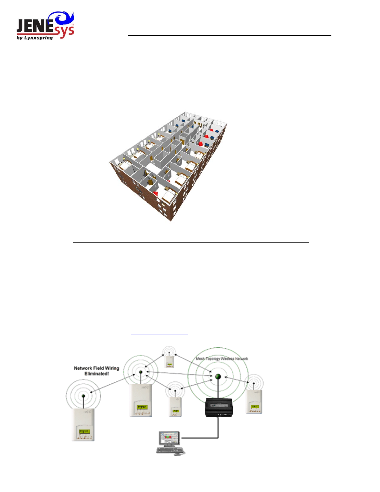
The application is targeted at retrofit applications where the addition of communicating field bus wiring within the
building space is prohibitive. The JENE communication card and associated Wireless Communicating
Thermostats encourage the use of existing wiring utilized by existing electronic thermostat type controls.
Additional documentation is available on www.lynxspring.com
®
powered JENE controllers.
®
environment.
1

Trademarks
Niagara, Niagara AX is a registered trademark of Tridium, Inc.
LON, LonWorks and LonTalk are registered trademarks of Echelon Corporation
BACnet is a registered trademark of ASHRAE
Disclaimers
NO WARRANTY. Lynxspring, Inc. (herein after referred to as “Lynxspring”) makes no warranty as to the
accuracy of or use of this technical documentation. Any use of the technical documentation or the information
contained therein is solely at the risk of the user.
Documentation may include technical or other inaccuracies or typographical errors. Lynxspring reserves the right
to make changes to this document without prior notice, and the reader should in all cases consult Lynxsprin g to
determine whether any such changes have been made. The information in this publication does not represent a
commitment on the part of Lynxspring.
Lynxspring shall not be liable for incidental or consequential damages resulting from the furnishing, performance,
or use of this material.
This guide contains links and references to third-party websites that are not under the control of Lynxspring, and
Lynxspring is not responsible for the content of any reference material or linked websites. If you access a third
party website mentioned in this guide, then you do so at your own risk. Lynxspring provides these links only as a
convenience, and the inclusion of the link does not imply that Lynxspring endorses or accepts any responsibility
for the content on those third-party sites.
Electronic controls are static sensitive devices. Discharge yourself properly before manipulation and installing
the Lynxspring wireless gateway.
All Lynxspring wireless gateways and related wireless thermostats are to be used only as operating controls.
Whenever a control failure could lead to personal injury and/or loss of property, it becomes the responsibility of
the user to add safety devices and/or alarm system to protect against such catastrophic failures.
All VT7000 series wireless thermostats and associated components have been rigorously tested to ensure
reliable operation in most building applications using the latest 2.4 ZigBee technologies. Lynxspring cannot
guarantee against potential network interference should additional wireless systems be deployed sharing close
proximity.
Best practices covered in this manual and all related Lynxspring documents should be considered as a guide to
apply Lynxspring Wireless Network devices only. The instructions included in this manual are based upon
Lynxspring in house testing and should be referred to as a guide only.
Lynxspring Inc. may not be held liable for continued reliable, or robust operation of any and all wireless based
devices. Although Lynxspring has taken many precautions in assuring the robustness of the VT7000 se ries
wireless thermostat product line and associated network access point (JENE’s with wireless option card) Please
note; future application of additional wireless devices utilizing the same or similar channels and / or frequencies
may degrade performance of overall system and / or reliability.
Non-approved modifications or changes made to the communication card, the wireless thermostat driver or
wireless thermostats may void the FCC compliance of the wireless card and wireless thermostats.
Ferrites supplied with the power supply and VWG MUST be installed according to instructions. Failure to do so
may void the FCC compliance of the wireless card and wireless thermostats.
THIS DEVICE COMPLIES WITH PART 15 OF THE FCC RULES. OPERATION IS SUBJECT TO THE
FOLLOWING TWO CONDITIONS: (1) THIS DEVICE MAY NOT CAUSE HARMFUL INTERFERENCE, AND (2)
THIS DEVICE MUST ACCEPT ANY INTERFERENCE RECEIVED, INCLUDING INTERFERENCE THAT MAY
CAUSE UNDESIRED OPERATION.
2
About Lynxspring Wireless Mesh Networks
The Lynxspring wireless card (VWG-APP-1020 ) and related wireless thermostat family (VT7xxxXxxxxW)
networkable devices operate using ZigBee/IEEE 802.15.4 physical layer for communication.
General characteristics of the wireless physical communication layer are:
• Uses a wireless physical layer of 2.4GHz with a data rates of 250 kbps
• Yields high throughput and low latency
• Automatic multiple topologies configuration: star, peer-to-peer, mesh
• Fully handshake protocol for transfer reliability
• Range: 30 feet / 10M typical (up to 100 feet / 30 M based on environment)
IEEE 802.15.4 along with ZigBee Networks and Application Support Layer provide:
• Low cost installation deployment
• Ease of implementation
• Reliable data transfer
• Short range operation
• Very low power consumption
• Appropriate levels of security
The JENE with the wireless communication card acts as network coordinator device for the IEEE
802.15.4/ZigBee network used with the Lynxspring wireless thermostats.
Many network specific features of the IEEE 802.15.4 standard are not covered in detail in this paper. However,
these are necessary for the efficient operation of a ZigBee network. These features of the network physical layer
include receiver energy detection, link quality indication and clear channel assessment. Both contention-ba sed
and contention-free channel access methods are supported with a maximum pa cket size of 128 bytes, which
includes a variable payload up to 104 bytes. Also employed are 64-bit IEEE and 16-bit short addressing,
supporting over 65,000 nodes per network. All those properties of the physical layer are used and employed by
the Lynxspring mesh network but are hidden to the installed / user for ease of configuration and commissioning of
the network database.
A “recommended” typical maximum of 30
Database creation and configuration is easily made using the Niagara AX
networkable thermostats can be supported by a single JENE2.
®
environment.
The theoretical maximum of number of thermostats supported by a single JENE is dependent on the resour ces
available for the WirelessStatNetwork driver Jar file and the extent of integration added to the station itself. When
additional functions and services are added to the station, the available resources for the driver will be less. Once
you have configured the station for the wireless network and all other features (graphics, services, histories,
alarms, etc.), you should monitor the resources so that they do not exceed the recommended limits for ea ch
specific platform.
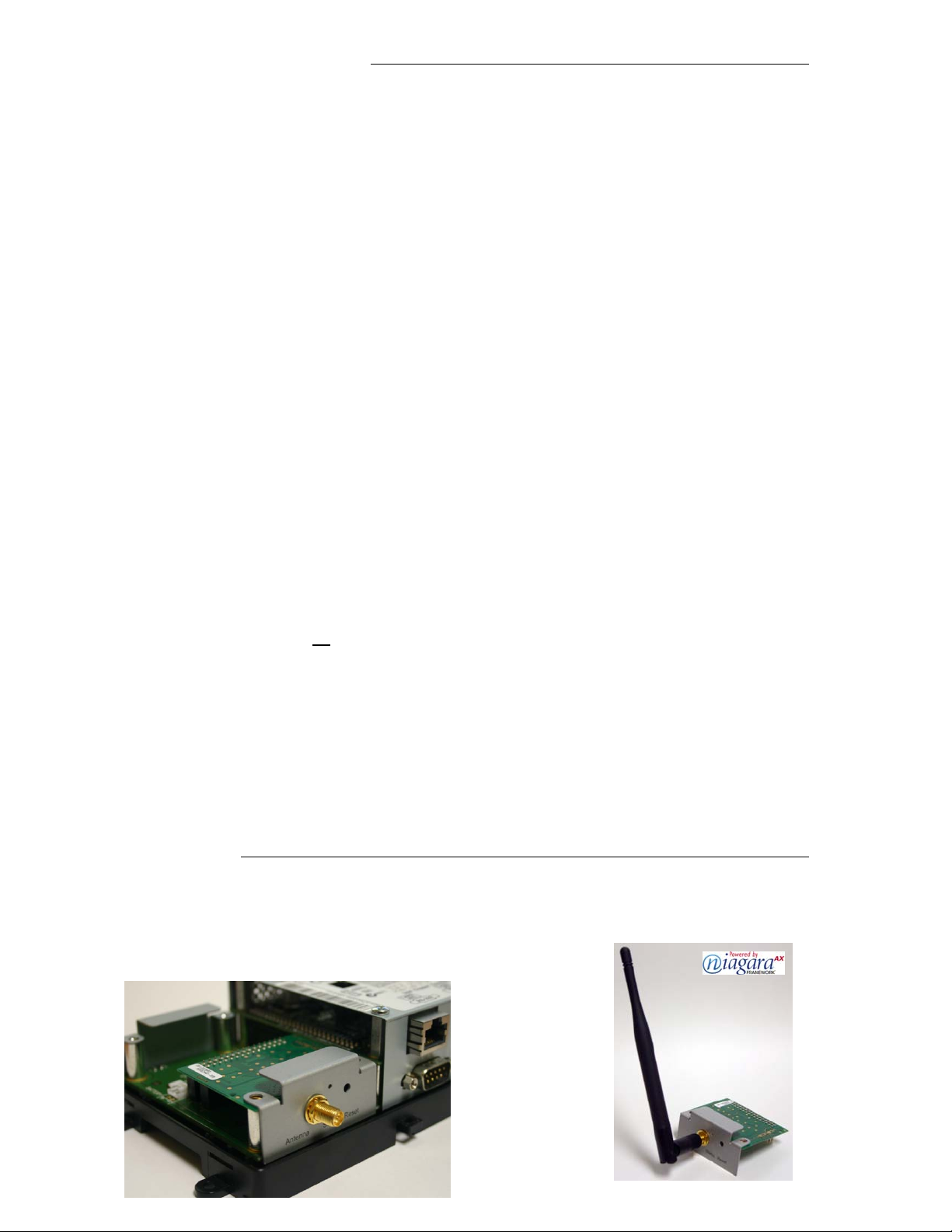
Wireless Card Installation
Please refer to the “Wireless Communication Card Installation” manual supplied with the VWG-APP-1020
communication card for detailed information on the wireless communication card installation inside a JENE
controller.
Only use Com1 option slot card position for the card
3
Basic Initial Design And Deployment Consideration
Proper design considerations need to be addressed prior to any installation of a JENE with a Lynxspring wireless
communication card and related wireless thermostats.
1. To properly avoid network interference with 802.11 Wi-Fi devices in the 2.4GHz spectrum range,
Lynxspring recommends the use of 802.15.4 channels 25 and 26 only. 802.11 Wi-Fi transmissions
overlap and may interfere with other channel selection allowed by 802.15.4 ( Channels 11 to 24 )
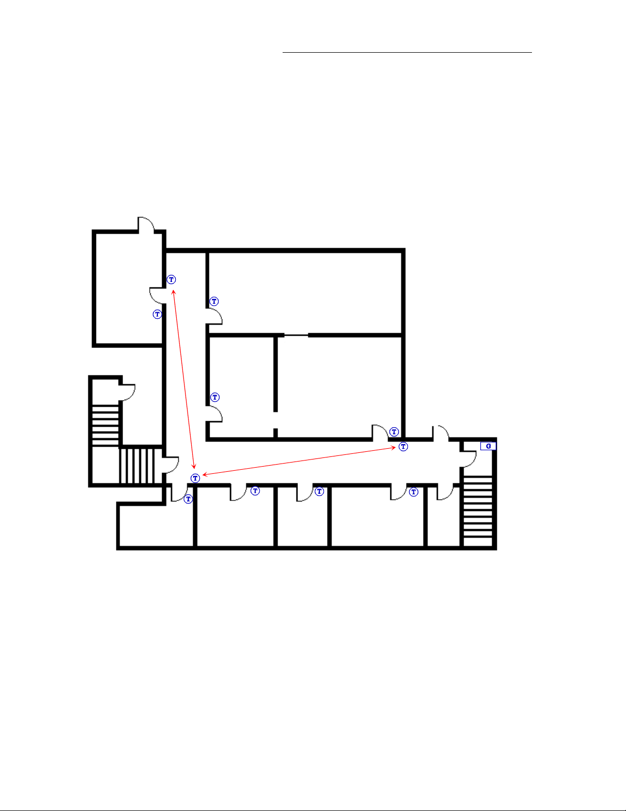
2. Maximum distance between each node ( thermostat ) should be:
• Clear line of sight between 2 nodes should be under 100 feet ( 30 M )
Open clear line of sight distance between
2 nodes should be a maximum of
100 feet ( 30 M )
Maximum 100 feet ( 30 M )
between 2 thermostat nodes
4
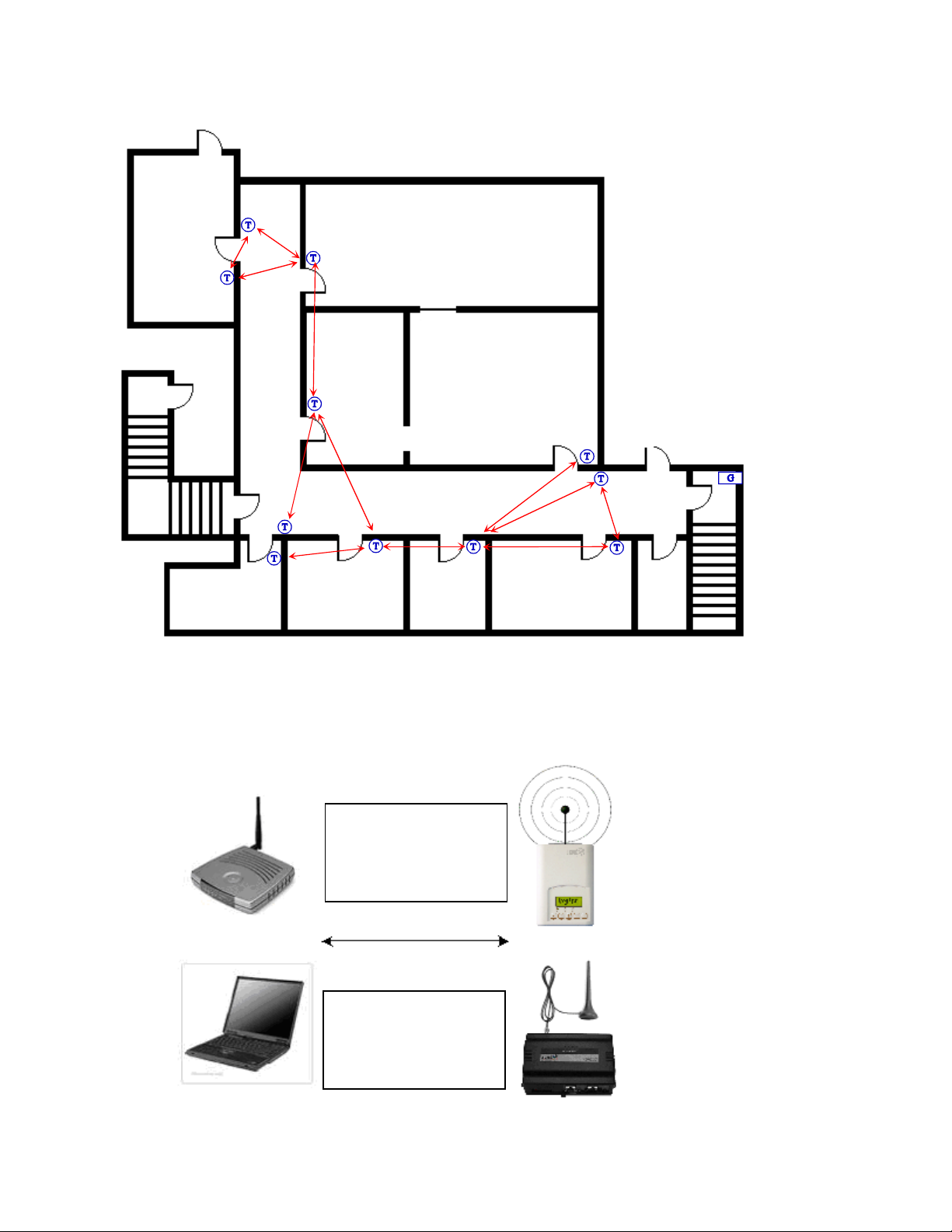
• Non line of sight, typical gypsum wall partitions made with metal stud frame should be under 30 feet (10M )
Non line of sight maximum distance
for typical gypsum wall partitions
should be maximum of 30 feet ( 10 M )
between 2-thermostat nodes
Maximum 30 feet ( 10 M )
between 2-thermostat nodes
3. Ensure that the minimum distance between any Lynxspring node and any Wi-Fi devices ( wireless
routers, wireless adapters, lap-tops using wireless networks, etc….) to be at least 3 foot ( 1 M ) and
preferably 10 feet ( 3 M ) or more.
Minimum 3 feet ( 1 M )
between Wi-Fi
equipment and
Lynxspring wireless
Preferably 10 feet ( 3 M ) or
more between Wi-Fi
equipment and Lynxspring
wireless devices
5
)
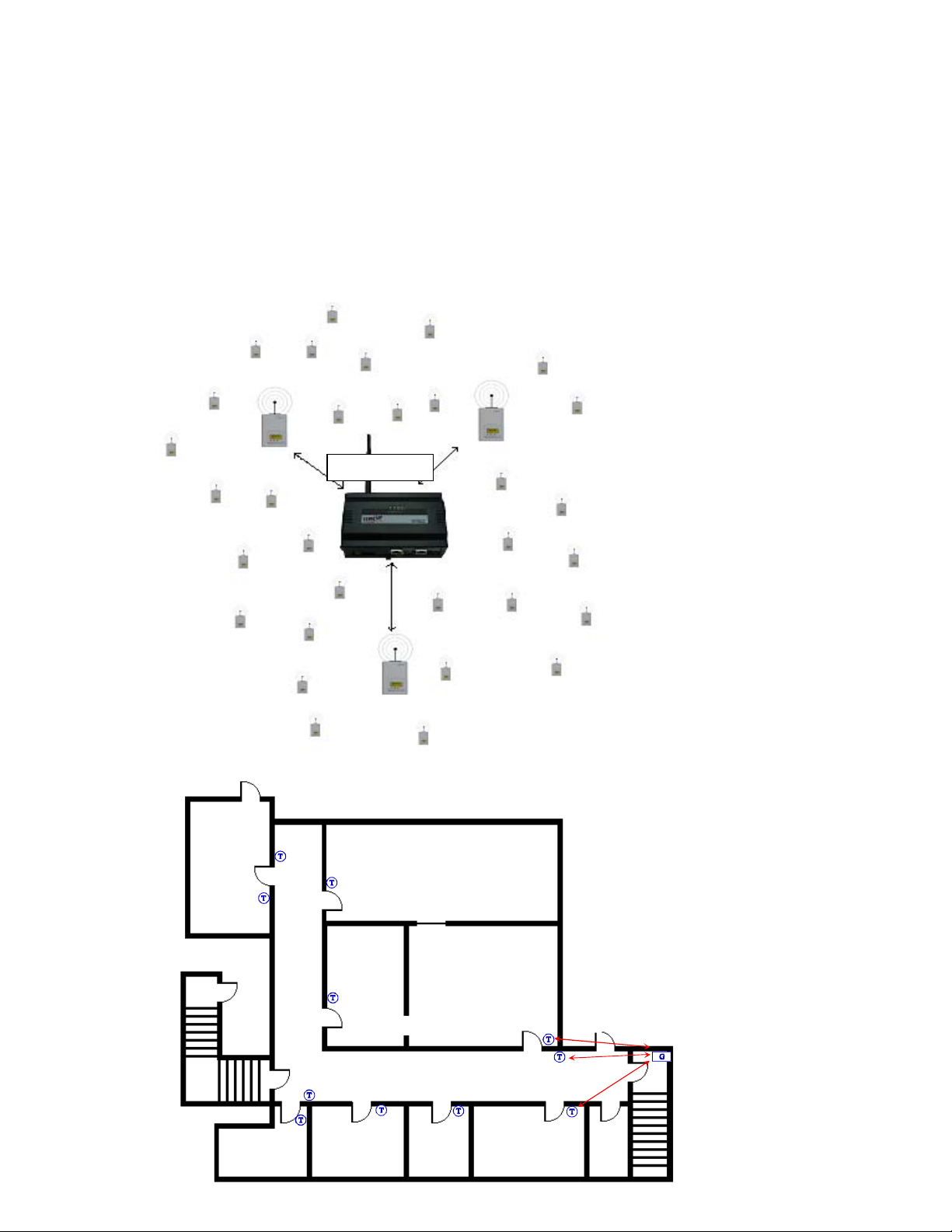
4. Ensure that at least one thermostat is within 30 feet of the VWG for every cluster of 10 thermostats
installed.
5. Always try to locate if possible the VWG near the center of all associated wireless thermostat s.
6. Always try to locate the VWG near on in line of sigh to as many wireless thermostats as possible.
7. Try to avoid metal, brick walls or concrete obstructions between wireless devices as much as possible.
8. Make sure the antenna on the VWG is always perpendicular to the floor.
9. Avoid placing VWG and thermostats near metal or enclosed in metal boxes. If the VWG needs to be
installed inside a metal cabinet, use the remote antenna accessory.
Ex. For a recommended maximum of 30 wireless thermostats total per JENE, a minimum of 3 of them should be
within 30 feet ( 9 M ) of the VWG range.
30 feet ( 9 M
At least 1 Viconics thermostat node
to be within 30 feet ( 9 M ) of the
VWG for every other 10 thermostat
installed
v
6
JENE and Wireless Communication Card Configuration
®
Initial Configuration Note: The following instructions assume you are familiar with the Niagara AX
environment and its related functions
• Install the wireless communication card as stipulated by the instructions provided with the wireless
card
• Copy the “WirelessStatNetwork” jar file to your local module folder
• Using the Software Manager, add the “WirelessStat” jar file to the target JENE with the wireless
communication card already installed
• Re-boot both the local Niagara AX
®
interface and the JENE itself to properly load the
“WirelessStatNetwork” jar module
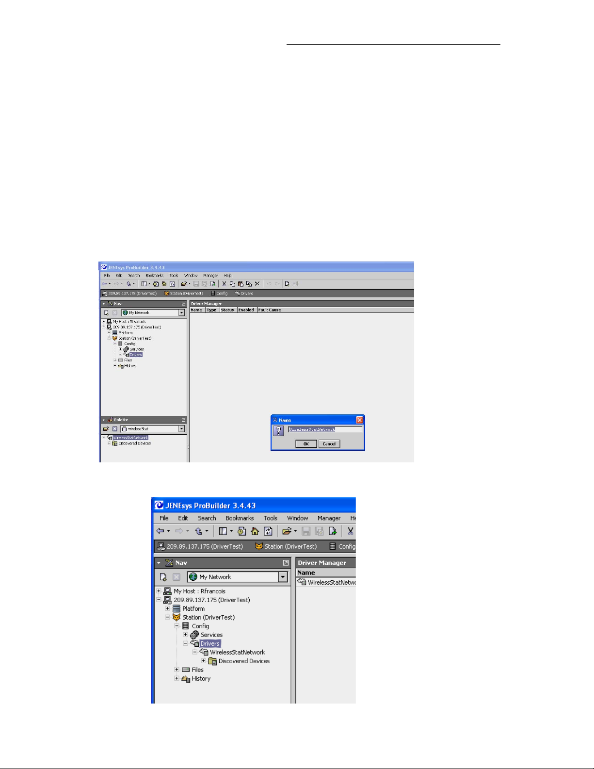
• Using the “WirelessStat” palette tool, simply drag & drop the “WirelessStatNetwork” driver under the
local driver folder of the JENE
• Rename the “WirelessStatNetwork” driver extension name if required
7
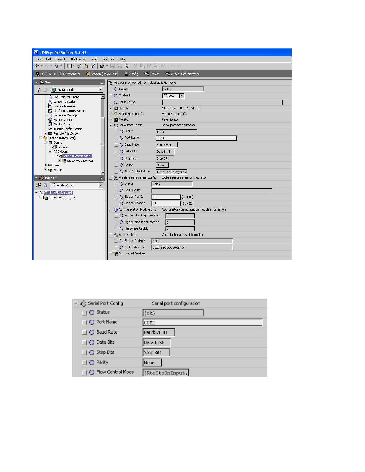
• Right hand click the “WirelessStatNetwork” driver and load the property sheet
• Under the Serial Port Configuration, set Port Name to “COM1”. Only COM1 can be used with the
wireless communication card. All other properties are locked and set as read only
8
 Loading...