


RobotShop Product Code: RB-Lyn-814
Lynxmotion SKU: AL5D-PLTW
Guide release date / version V1.2 March 2018
RobotShop Inc. 305-18005 Lapointe Mirabel, Quebec, Canada J7J0G2

About 2
Lynxmotion / RobotShop 2
AL5D Robot Arm 2
What’s Included 3
Part Codes 4
Tools Required 5
RC Servo Technology 6
Angle 6
Torque 6
Operation 6
Assembly 7
A. Base 7
B. Arm Assembly 17
C. Servo Installation 27
D. Software / Servo Setup 37
E. Cleanup & Mounting 45
Important Notes 52
Warranty Information 52
RobotShop Inc. 305-18005 Lapointe, Mirabel, Quebec, Canada, J7J0G2
1
About
Lynxmotion / RobotShop
Lynxmotion offers a variety of hobby and research level robot kits and parts, most precisely the
modular robotics building system known as the Lynxmotion Servo Erector Set.
Imagine it. Built it. control it.™
Founded in 2003, RobotShop Inc. is proud to put robotics at your service. We specialize in
personal and professional robot technology and offer a wide range of robotic products and
services in this sector. RobotShop acquired Lynxmotion in late 2012.
Putting robotics at your service!
At RobotShop, our vision is to be the World leading source for personal and professional robot
technology that help increase the pleasure, knowledge, liberty and security of individuals. We
are also committed to promoting and advocating the interest and necessity of robotics use
towards positive ends, allowing humanity to attain a better world.
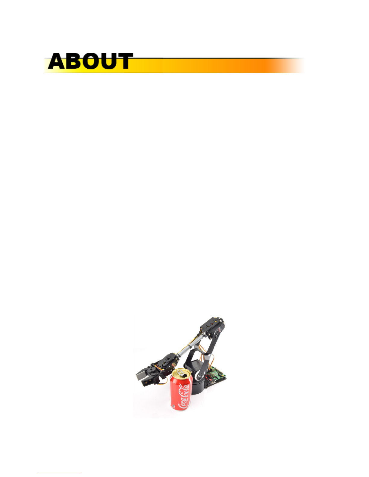
AL5D Robot Arm
The AL5D - PLTW arm is part of Lynxmotion’s series of AL5 robot arms (AL5A, AL5B and AL5D;
the AL5C was discontinued). The AL5D robotic arm delivers fast, accurate, and repeatable
movement. The robot features: base rotation, single plane shoulder, elbow, wrist motion, a
functional gripper, and medium duty wrist rotate. The AL5D robotic arm is an affordable system
with a time tested design that will last.
Standard AL5D Robot Arm
RobotShop Inc. 305-18005 Lapointe, Mirabel, Quebec, Canada, J7J0G2
2

What’s Included
NOTE: The assembly guide provided in this document is not the same as the assembly guide
provided online via Lynxmotion or on YouTube. We suggest using this guide only.
If you purchase the AL5D-PLTW (RB-Lyn-814) arm, it will include everything mentioned below.
The arm does not require any additional parts for use with the Project Lead The Way curriculum,
though additional accessories are available separately.
Standard AL5D
● 1x AL5D 4 Degrees of Freedom Robotic Arm (Hardware Only)
● 1x SSC-32U USB Servo Controller
● 1x Power Supply Output 6VDC 5A Input 120-240VAC
● 1x HS-422 Servo Motor (gripper)
● 1x HS-645MG Servo Motor (wrist)
● 1x HS-755HB Giant Scale Servo Motor (elbow)
● 1x HS-805BB Giant Scale Servo Motor (shoulder)
● 1x HS-485HB Servo Motor (base)
AL5D - PLTW
The PLTW version of the AL5D (RB-Lyn-814) includes additional upgrades:
● 1x FlowArm PLTW Software (on CD with licence printed on the invoice / packing slip)
● 1x Medium duty wrist rotate with 1x HS-422 servo
● 1x Servo extension cable
The arm is packaged by sub-sections - for example, the hardware for constructing the frame of
the arm is provided in its own bag, complete with screws and nuts. The base rotate kit is
packaged separately in its own bag with all corresponding hardware. It is up to the customer if
they prefer to keep these packages separate, or to open all packages and combine identical
products.
RobotShop Inc. 305-18005 Lapointe, Mirabel, Quebec, Canada, J7J0G2
3
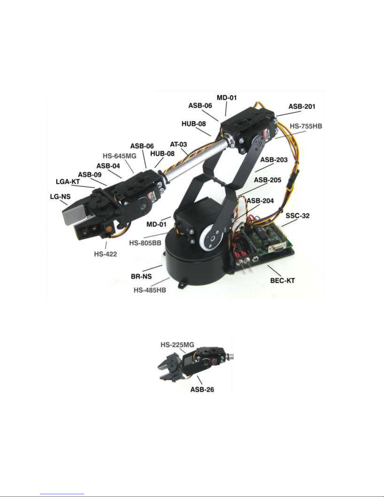
Part Codes
The following diagram illustrates the parts (Lynxmotion codes) used to make the standard AL5D
arm (without the additional parts for PLTW).
Standard AL5D Robot Arm (V1) w. Old SSC-32
Medium duty wrist rotate upgrade
RobotShop Inc. 305-18005 Lapointe, Mirabel, Quebec, Canada, J7J0G2
4

Note: We include a variety of additional parts which you will not use in the construction of the
arm. This is because the AL5D-PLTW is nevertheless part of a modular building system, and
parts / kits which make up the arm are also used in other kits.
Tools Required
Several standard tools are needed for the assembly of the arm, most notably:
● 3-30 Hex wrench suitable for the 4-40 screws (included)
● Phillips head screwdriver
● Small pan head screwdriver (for SSC-32U screw terminals)
● Wrench (for 2-56 nuts)
● 400 grit sandpaper (optional)
● Silicon based oil (optional)
Mechanics
The aluminum robotic arm is made using the Lynxmotion Servo Erector Set components for the
ultimate in flexibility and expandability. The kit consists of aluminum brackets, aluminum tubing,
custom injection molded components, and precision laser-cut Lexan components.
Dimensions
● Shoulder to elbow: 5.75”
● Elbow to wrist: 7.375”
● Wrist to tip of gripper: 3.375”
● Height (arm packed): approx. 7.25”
● Height (reaching up): approx. 19.00”
● Median forward reach: approx. 10.25”
● Gripper opening: 1.25”
● Weight: 31oz
● Range of motion per axis: 180 degrees
● Medium duty wrist rotate ads 1”
Load Capacity
The load capacity of the arm is based on multiple factors:
● Operating voltage: RC servos can accept between 4.8V to 6V
● Distance from the base: This factor is critical since the farther the object is from the
base, the more energy will be required to hold it against gravity
● Length of time the object is held: The longer the object is held against gravity, the more
the servos will heat up.
At median reach (elbow at 90 degrees), the arm can support up to 10 oz. As the arm is
extended, it will support a bit less, and as it is retracted, it can support a bit more.
RobotShop Inc. 305-18005 Lapointe, Mirabel, Quebec, Canada, J7J0G2
5
RC Servo
Technology
The AL5D uses Hitec RC servo motor actuators at each joint. These servos are classically used
in the RC hobby industry to control ailerons and landing gear on airplanes, rack and pinion
steering on RC cars and come in a variety of sizes and torque ratings. Given their popularity,
easy of use, low price and absolute positioning, RC servos were adapted for use in animatronics
and robotics.
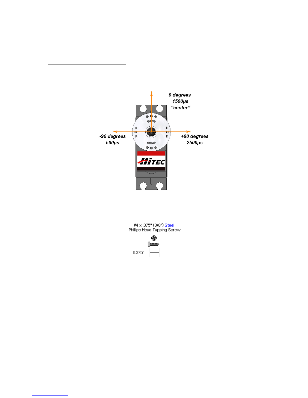
Angle
Standard RC servo motors only rotate 180 degrees (0 to 180 / -90 to +90). This is the case
because the internal component (rotary potentiometer) which provides the absolute positioning,
cannot provide multiple rotations and is physically limited in the angle over which it can turn.
Torque
“Torque” is not the same as a “force”; a “force” acts as a straight vector, whereas “torque” is
rotational about a point. Torque is defined as force multiplied by distance, or T = F * d, where d
is the distance between the force and the axis of rotation. Although we will not go into the details
of how to calculate torque, it is important to note that not all servos can provide the same torque,
and some are more powerful than others.
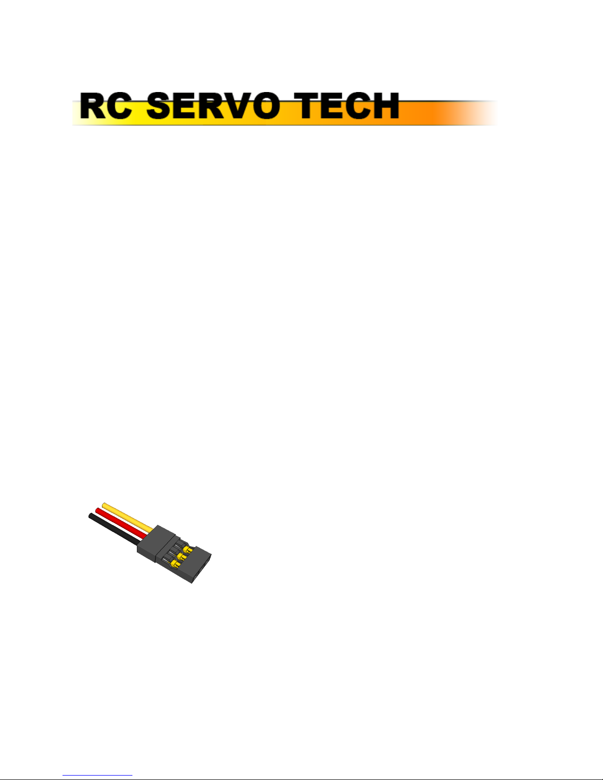
Operation
AN RC servo motor has three wires which are always in the same order:
Black = Ground (GND)
Red = Positive (4.8V ~ 6V)
Yellow = PWM Signal / Pulse
An RC PWM signal is a repeated pulse at 5V whose duration lasts between 0.5ms (500us) to
2.5ms (2500us), followed by a delay of between 20ms to 30ms. The servo’s onboard electronics
time the pulse and position the servo at the corresponding angle. The pulse must be repeated
for the servo to retain the desired position.
RobotShop Inc. 305-18005 Lapointe, Mirabel, Quebec, Canada, J7J0G2
6
Assembly
Note that there is also an online assembly guide from Lynxmotion for the AL5D (which uses
photos), as well as a YouTube video, however this manual is an updated version, so we suggest
using ONLY this guide for the assembly steps.
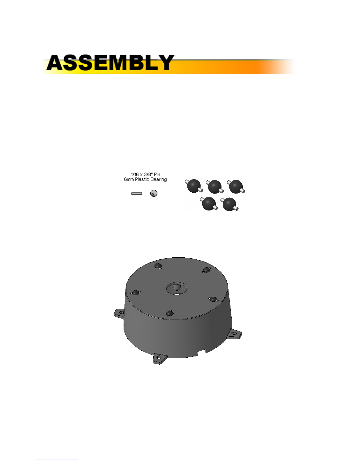
A. Base
Step A1 : Insert the 1/16” x ⅜” stainless steel pins into the 6mm black plastic beads as shown
(5x)
● 5x steel pins
● 5x plastic beads
Step A2 : Install the bearings into the base as shown. They will fit snugly. Note, the notch in the
bottom edge of the base (shown below) indicates the back.
● 5x plastic bead assemblies
● 1x base rotate (bottom)
RobotShop Inc. 305-18005 Lapointe, Mirabel, Quebec, Canada, J7J0G2
7
Step A3 (optional): Lay a piece of 400 grit sandpaper (not included) on a flat surface and
carefully turn the base assembly from step 2 upside down. Press the base against the
sandpaper in small circles on it to remove any imperfections on the beads.
Step A4 (optional): The image below shows the circle pattern on the sandpaper and the inset
shows the bearings after any imperfections have been removed.
RobotShop Inc. 305-18005 Lapointe, Mirabel, Quebec, Canada, J7J0G2
8
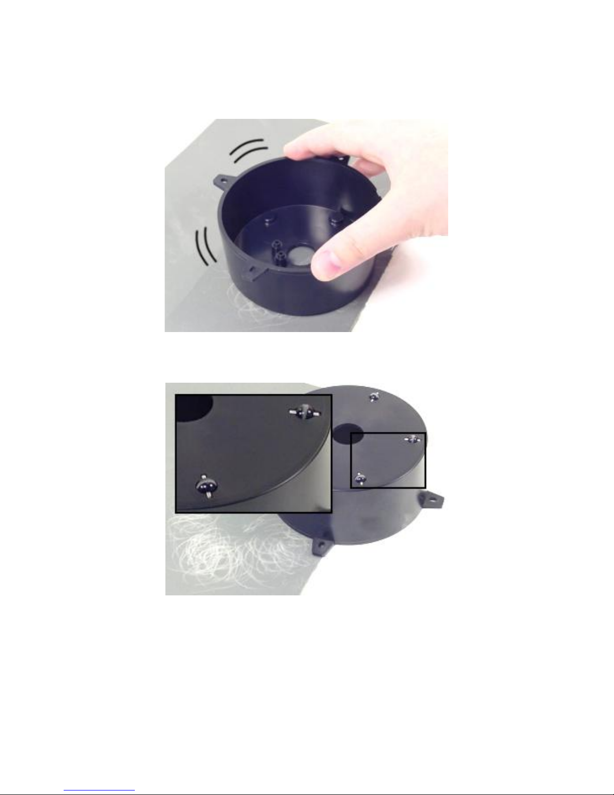
Step A5 : The Hitec 485HB servo is shipped with its white plastic horn centered. If the horn is
rotated by accident, ensure it lines up like the image below. It should rotate 90 degrees CCW
and 90 degrees CW. Unscrew the black screw holding the horn in place and KEEP IT for step
A9). Note that this screw is very tight and the appropriate screwdriver (correct Phillips head) is
needed. Apply some downward pressure but do not strip the screw . If the servo horn was
rotated, re-center it as in the image below, then pull the white plastic horn straight off of the
servo.
Step A6 : Place the servo in the base as shown and screw it in using four #4 x ⅜” Phillips head
tapping screws included with the base rotate kit. Note that the holes are not tapped - the screws
need to be turned and pressed to force thread the plastic.
RobotShop Inc. 305-18005 Lapointe, Mirabel, Quebec, Canada, J7J0G2
9
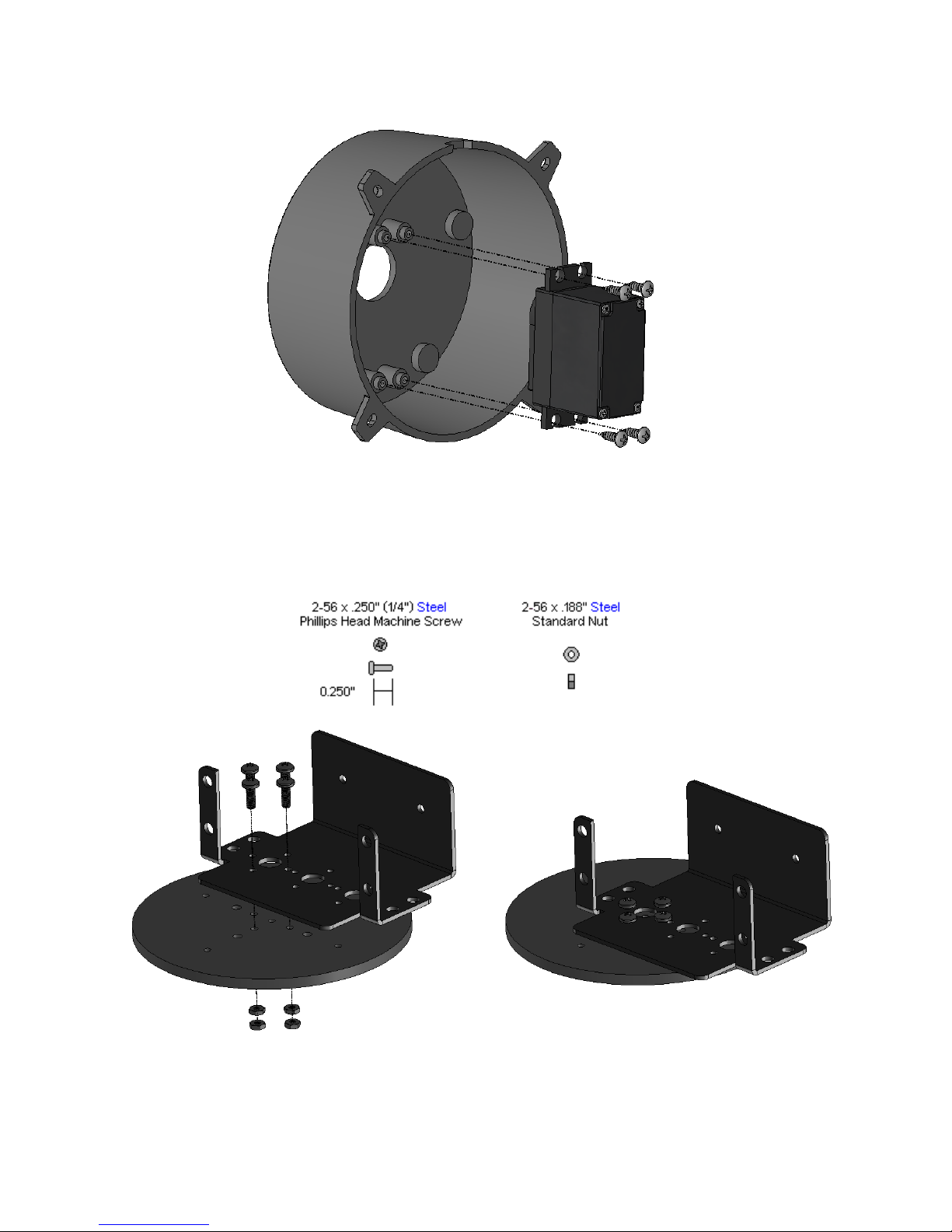
Step A7 : Attach the large ASB-204 multipurpose bracket onto the base top using four 2-56 x
.250" phillips head machine screws and four 2-56 nuts as shown. Note, the bracket and
hardware are included in the arm kit, not the base kit. Ensure the orientation looks like the
image below.
Step A8 (optional to reduce noise): Add a drop of silicone-based oil to each bearing (not
included)
RobotShop Inc. 305-18005 Lapointe, Mirabel, Quebec, Canada, J7J0G2
10
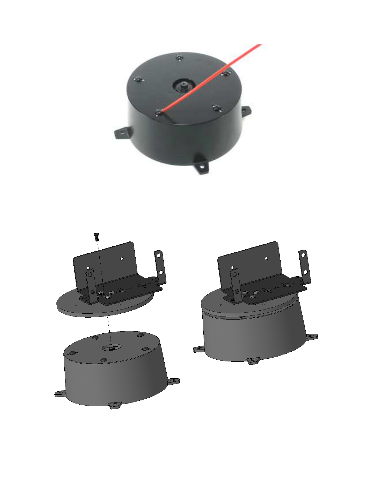
Step A9 : Install the base top using the horn screw from step A5. The hole pattern of the top
plate should line up with one row of holes pointing to the servo wire hole at the rear, and all of
the lines pointing between the mounting tabs. Note, this top piece is manufactured to be a tight
fit to the servo horn, so be sure to align them well and you might have to press hard.
Step A10 : Pass the servo's cable through the hole in the back of the base. This will keep the
base level to the mounting surface.
RobotShop Inc. 305-18005 Lapointe, Mirabel, Quebec, Canada, J7J0G2
11
NOTE: There are now two options for mounting the electronics. Choose one of the two.
Option 1: Lynxmotion Base Rotate / Heavy Duty Base to VEX Adapter
Option 2: Lynxmotion Base Electronics Carrier Kit
OPTION 1 (AL5 to VEX plate)
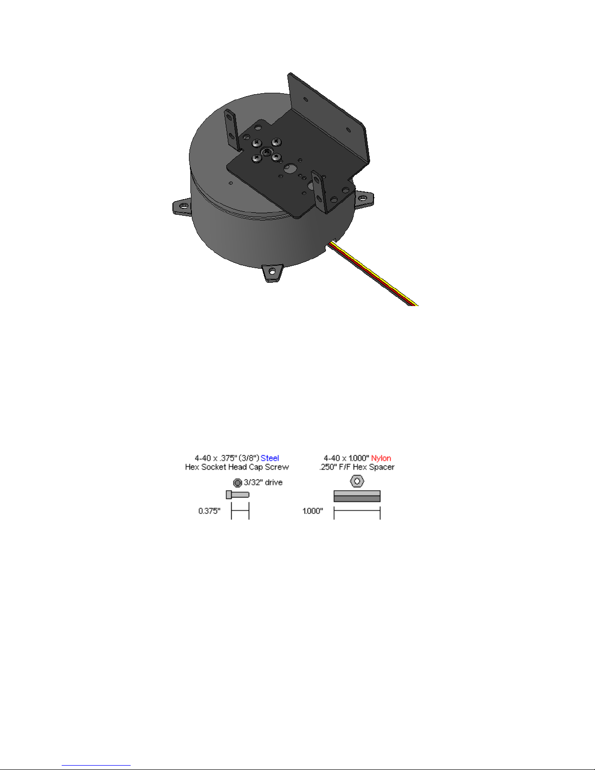
Step A11 : Screw four 4-40 x 1” long standoffs included with the Lynxmotion to VEX Adapter to
the plate using four 4-40 x ⅜” long hex screws.
RobotShop Inc. 305-18005 Lapointe, Mirabel, Quebec, Canada, J7J0G2
12
Step A12 : Use two 4-40 x ⅜” hex screws and two 4-40 x ¼” lock nuts to fix the
RobotShop Inc. 305-18005 Lapointe, Mirabel, Quebec, Canada, J7J0G2
13
RobotShop Inc. 305-18005 Lapointe, Mirabel, Quebec, Canada, J7J0G2
14
Step A13 : Install the power plug wiring harness as shown (servo controller greyed out). To do
so, you need to remove the nuts and spacers which come installed on both the switch and
barrel connector. You can use a tie wrap or tape to hold the wires in place. The SSC-32U only
needs the one wiring harness.
Note that the On/Off switch has three pins, of which two have wires. When the switch points
towards these two connectors, electricity can flow. In the image below, the switch would be OFF.
The orientation when inserted into the hole can be vertical (as shown in the image above) or
horizontal); just know which is ON and OFF.
Switch in the OFF position
RobotShop Inc. 305-18005 Lapointe, Mirabel, Quebec, Canada, J7J0G2
15
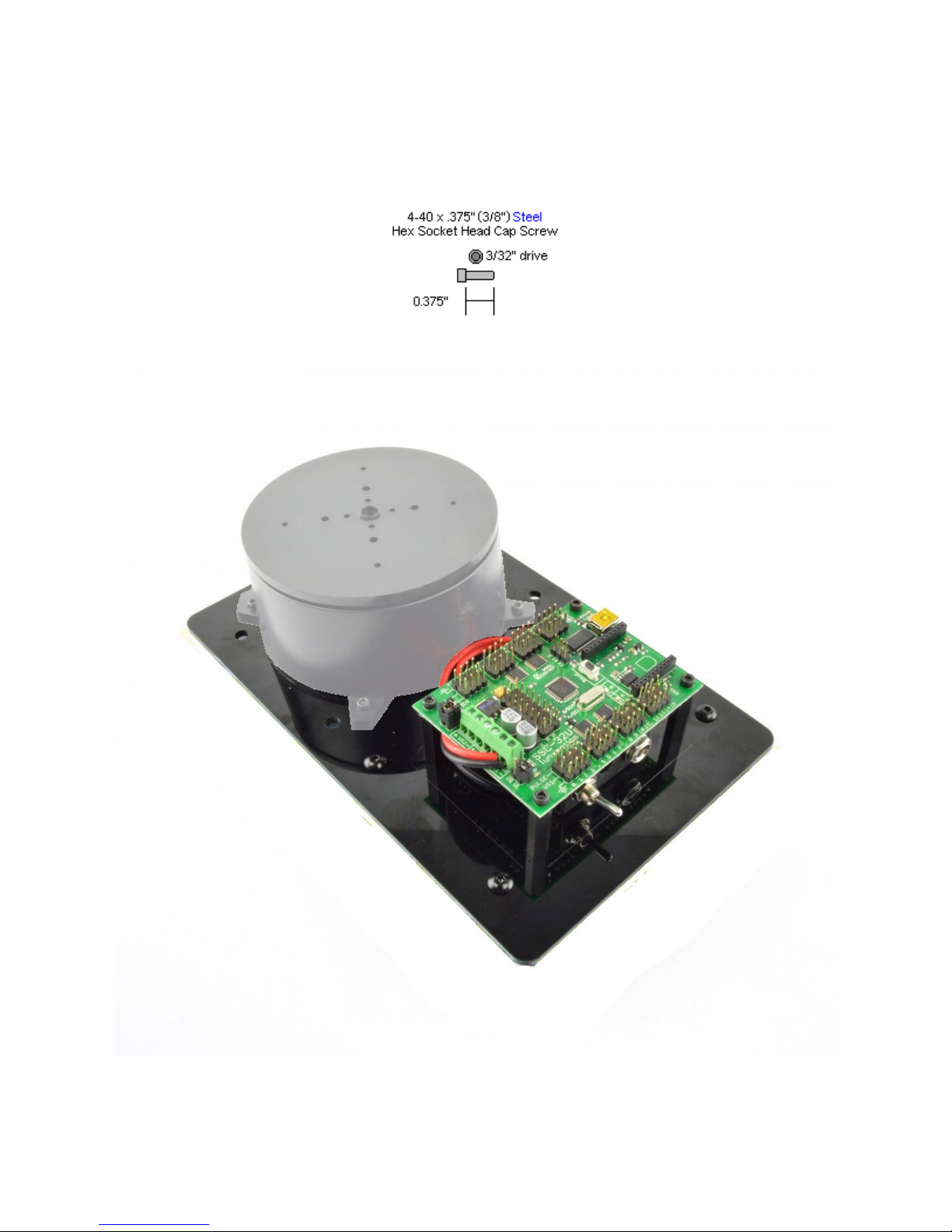
Step A14 : Install the SSC-32 (shown) or the SSC-32U using four more 1/4" x 3/8" hex socket
screws. Do not make the electrical connections yet. The base rotate is shown just for reference
so you know where it will be placed later.
RobotShop Inc. 305-18005 Lapointe, Mirabel, Quebec, Canada, J7J0G2
16
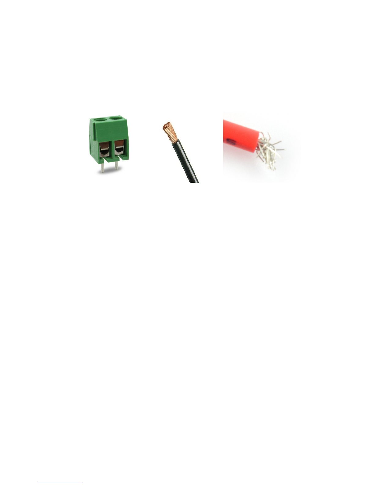
Step A15 : Twist each end of the multi-strand wires to ensure there are no loose wires which can
cause a short circuit. This will also make the multi-strand wires easier to insert into the screw
terminal.
Unscrew the VS1+ and VS1- terminals so the wires can be inserted. This means rotating the
screw so that the inner metal touches the bottom of the plastic (see visually). Screwing in the
opposite direction will create a bottom-up“clamping” effect which will hold the wire in place.
Screw terminal Clean Wires Bad Wires
Insert the wires to the VS1 input as shown, between the top bent metal and the bottom metal,
making sure the black wires goes to (-) and the red wires goes to (+). Tighten the screws to
ensure the wires are secure, and verify that there are no loose strands which may cause a short
circuit.
If you find it difficult to insert all of the wire strands, or they are too “messy”, use wire cutters (or
sharp scissors) to remove some of the shielding at the end (~0.5cm) and then carefully cut
some of the wire, ensuring all of the wires are straight and compact.
NOTE: Once again, ensure no wires touch between the red and black leads at the screw
terminals!
RobotShop Inc. 305-18005 Lapointe, Mirabel, Quebec, Canada, J7J0G2
17
OPTION 2
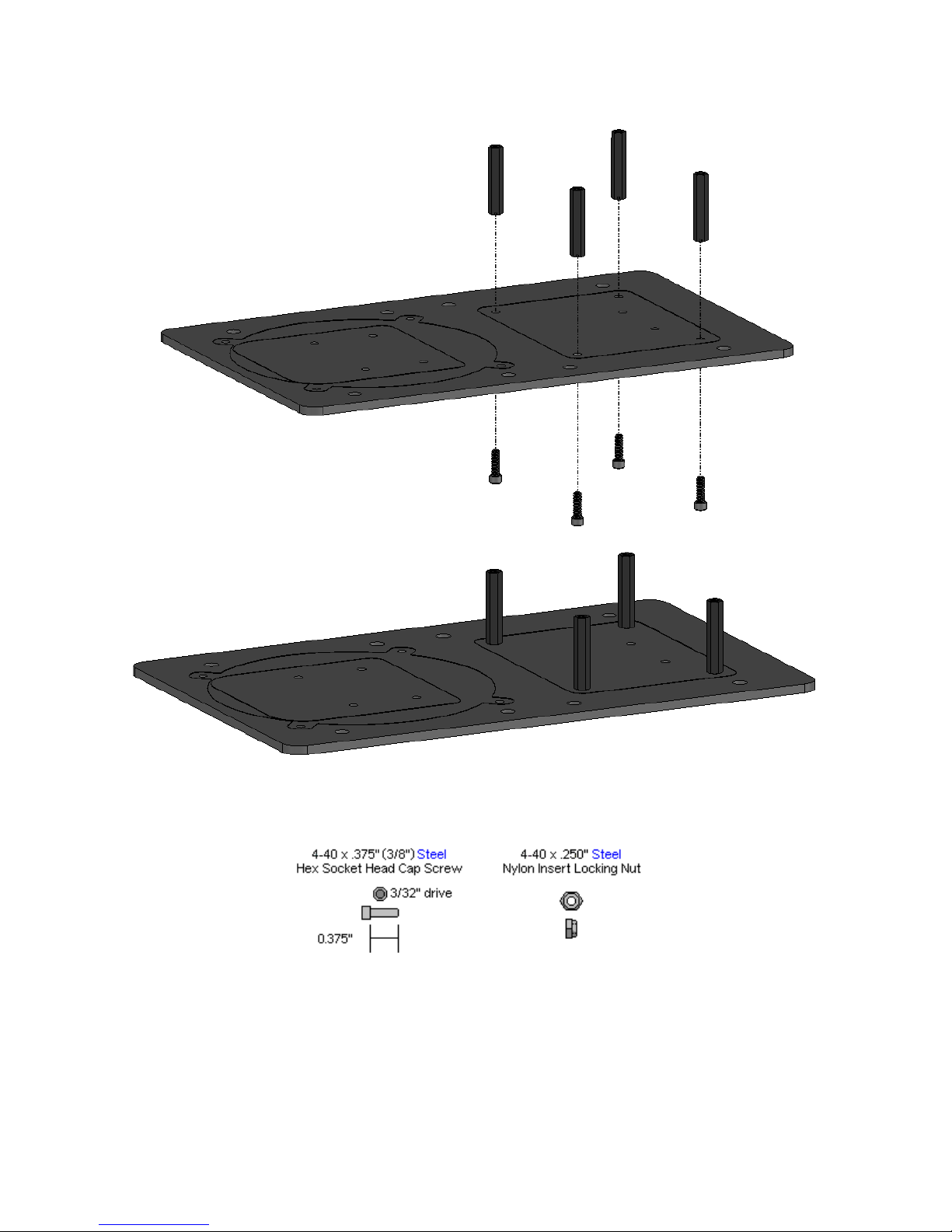
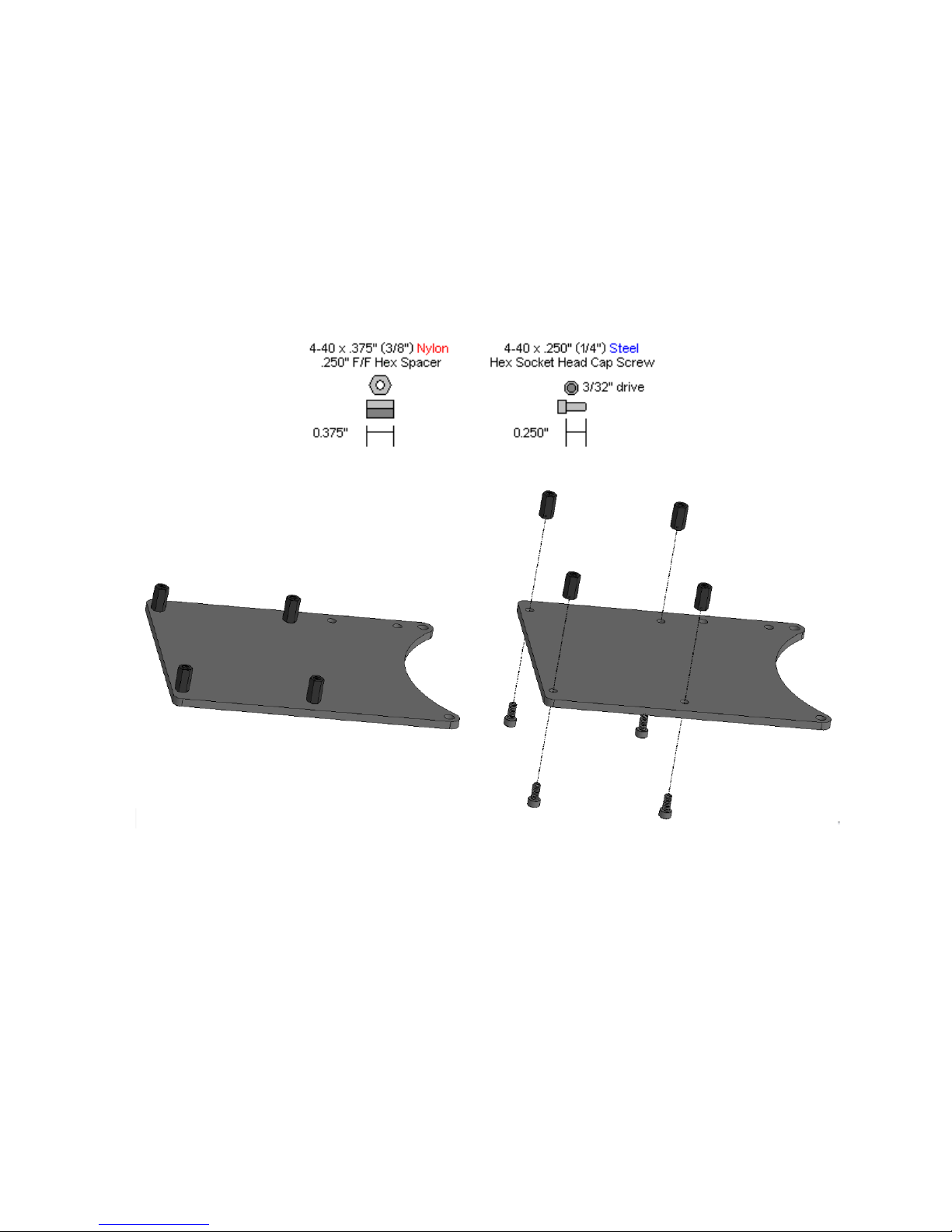
Step A11 : Attach four 4-40 x 3/8" hex spacers as shown using four 1/4" long hex socket screws.
Note that the lexan plate can be in either orientation - whichever works best for you. The
orientation below is “standard”.
Note: If you have purchased the Lynxmotion Base Rotate / Heavy Duty Base to VEX Adapter,
you will not need this plate and must use that adapter plate instead for these steps.
RobotShop Inc. 305-18005 Lapointe, Mirabel, Quebec, Canada, J7J0G2
18
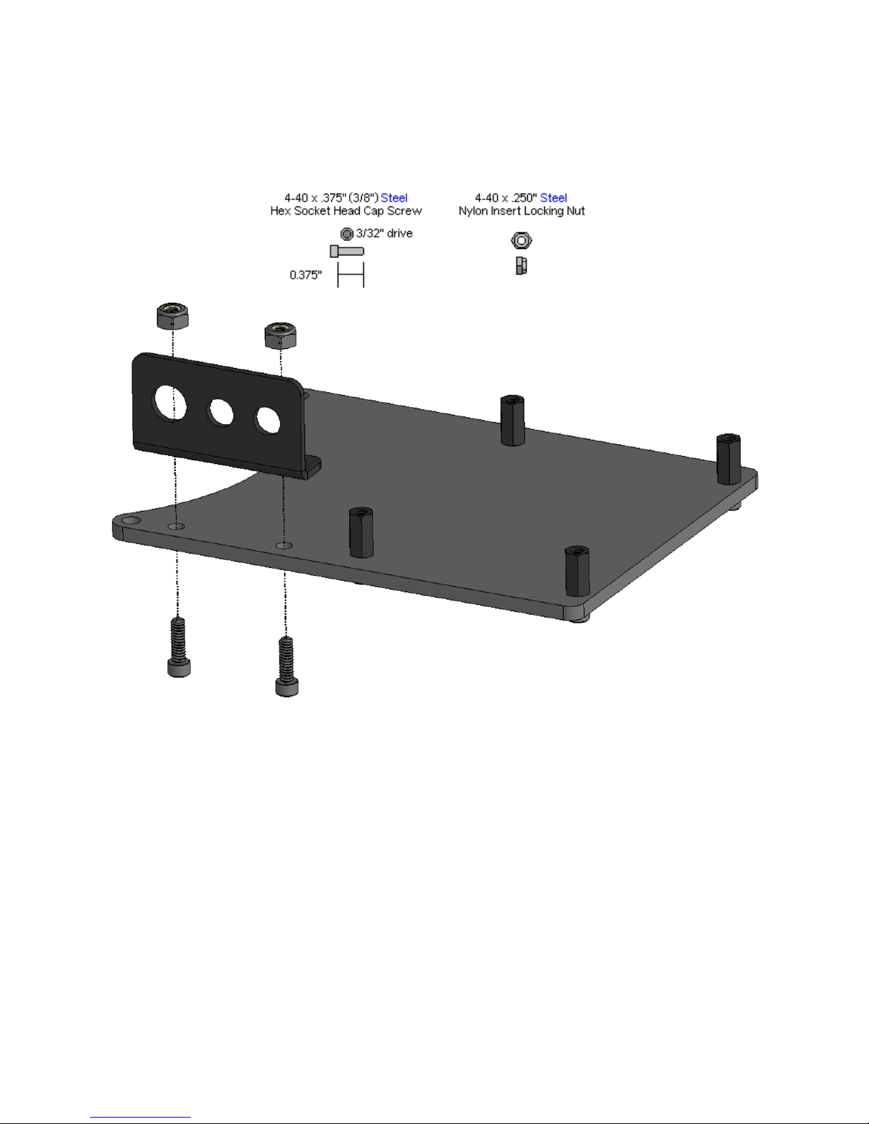
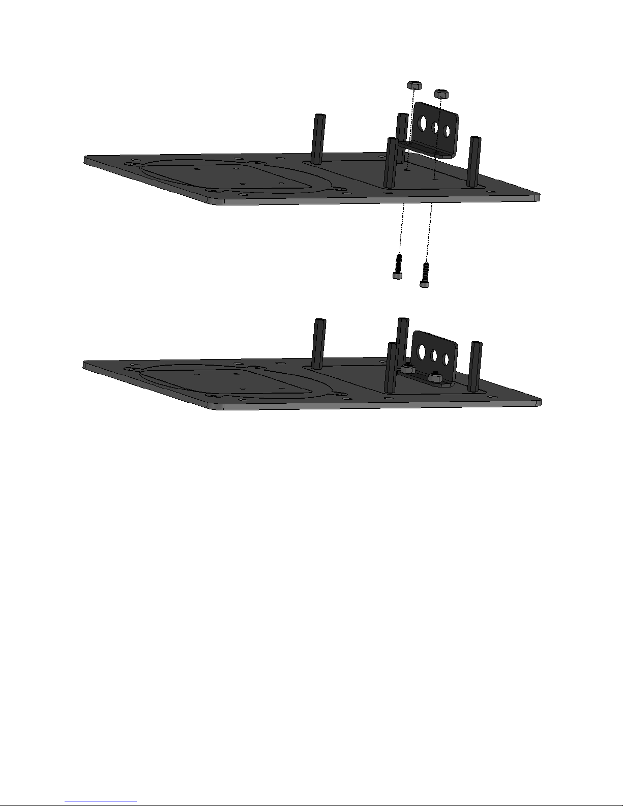
Step A12 : Install the power switch bracket using two 4-40 x 3/8" hex socket screws and two
4-40 nylon insert lock nuts, ensuring the bracket is on the same side as the standoffs. The
bracket can be on the left or the right side - whichever works best for your application.
RobotShop Inc. 305-18005 Lapointe, Mirabel, Quebec, Canada, J7J0G2
19

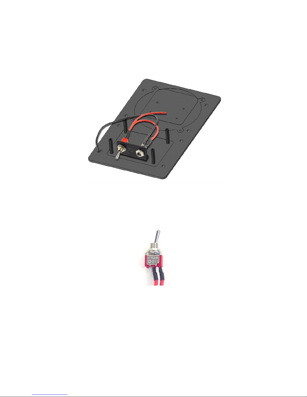
Step A13 : Install the power plug wiring harness as shown (servo controller greyed out). To do
so, you need to remove the nuts and spacers which come installed on both the switch and
barrel connector. You can use a tie wrap or tape to hold the wires in place. The SSC-32U only
needs the one wiring harness.
Note that the On/Off switch has three pins, of which two have wires. When the switch points
towards these two connectors, electricity can flow. In the image below, the switch would be OFF.
Switch in the OFF position
RobotShop Inc. 305-18005 Lapointe, Mirabel, Quebec, Canada, J7J0G2
20

Step A14 : Install the SSC-32 (shown) or the SSC-32U using four more 1/4" hex socket screws.
Do not make the electrical connections yet.
Step A15 : Twist each end of the multi-strand wires to ensure there are no loose wires which can
cause a short circuit. This will also make the multi-strand wires easier to insert into the screw
terminal.
Unscrew the VS1+ and VS1- terminals so the wires can be inserted. This means rotating the
screw so that the inner metal touches the bottom of the plastic (see visually). Screwing in the
opposite direction will create a bottom-up“clamping” effect which will hold the wire in place.
Screw terminal Clean Wires Bad Wires
Insert the wires to the VS1 input as shown, between the top bent metal and the bottom metal,
making sure the black wires goes to (-) and the red wires goes to (+). Tighten the screws to
ensure the wires are secure, and verify that there are no loose strands which may cause a short
circuit.
RobotShop Inc. 305-18005 Lapointe, Mirabel, Quebec, Canada, J7J0G2
21

If you find it difficult to insert all of the wire strands, or they are too “messy”, use wire cutters (or
sharp scissors) to remove some of the shielding at the end (~0.5cm) and then carefully cut
some of the wire, ensuring all of the wires are straight and compact.
NOTE: Once again, ensure no wires touch between the red and black leads at the screw
terminals!
RobotShop Inc. 305-18005 Lapointe, Mirabel, Quebec, Canada, J7J0G2
22

B. Arm Assembly
Step B1 : Connect the a large "C" bracket (ASB-203) and an 805 "C" bracket (ASB-205)
together as shown using two 2-56 x 1/4" screws and two 2-56 nuts.
RobotShop Inc. 305-18005 Lapointe, Mirabel, Quebec, Canada, J7J0G2
23

Step B2 : The dampening panels / discs used in this step are laser cut lexan pieces (two circles).
They have a protective covering that needs to be removed from both sides before assembly.
You can also break the two circles apart. The yellow powder is residue from the laser cutting
process.
Remove plastic covering from both sides
When the laser cuts, the covering melts into the cut edge which can make removal difficult. If
you gently scrape the cut edge with a flat blade screwdriver or scissors, the covering can easily
be lifted and peeled off.
Take a look at the following three images. Install the mechanical dampening panels as shown
using four 2-56 x ¼” machine screws. Be sure to add the discs to the correct sides and ensure
the holes in the upper disk line up with the holes in the lower disk. We suggest placing the side
around the edge of a table to allow you to press down when screwing to ensure there is no gap
between the Lexan and the aluminum (without deforming the bracket). This will force thread the
screw into the Lexan.
RobotShop Inc. 305-18005 Lapointe, Mirabel, Quebec, Canada, J7J0G2
24

The panels with the larger holes are on the outside of the bracket.
RobotShop Inc. 305-18005 Lapointe, Mirabel, Quebec, Canada, J7J0G2
25

Step B3 : Insert a 4-40 x 0.5" Phillips head screw through the hole in the multi-purpose bracket
as shown. Secure with a steel nut. Ensure the right screw is used.
RobotShop Inc. 305-18005 Lapointe, Mirabel, Quebec, Canada, J7J0G2
26

RobotShop Inc. 305-18005 Lapointe, Mirabel, Quebec, Canada, J7J0G2
27

Step B4 : Slide the large "C" bracket end of the bracket assembly over the screw as shown, and
secure with a 4-40 lock nut. The amount of friction can be adjusted by tightening or loosening
the lock nut. Start with the nut loose, and if the arm seems to wobble a bit, you can tighten this
joint to correct the wobble. It should rotate freely.
CAUTION: Don't over-tighten this nut! If the arm is operated with the mechanical dampeners too
tight, the servo WILL heat up and can be damaged!
RobotShop Inc. 305-18005 Lapointe, Mirabel, Quebec, Canada, J7J0G2
28

Step B6 : Attach the tubing connector hub to the short side of the "L" bracket using two 2-56 x
.250 screws and 2-56 nuts. Orientation of the screws, tubing connector and bracket are
important ; the hole in the tubing connector should be as shown, so the tube lines up as in figure
7. The shorter size of the L-bracket is used. Create two sub-assemblies.
RobotShop Inc. 305-18005 Lapointe, Mirabel, Quebec, Canada, J7J0G2
29

Step B7 : Connect the hub sub-assemblies from step B6 to the 4.50" tube using two 4-40 x .250"
screws. Tighten these screws well as they have a tendency to want to unscrew themselves
during operation.
RobotShop Inc. 305-18005 Lapointe, Mirabel, Quebec, Canada, J7J0G2
30

Step B8 : Attach one end of the tubing structure to a Standard Multi-Purpose bracket and the
other end to a Large Multi-Purpose bracket as shown in the image, using two 2-56 x .250
screws and two 2-56 nuts for each bracket. Orientation is important, as well as which holes are
used for the screws, so follow the image below.
RobotShop Inc. 305-18005 Lapointe, Mirabel, Quebec, Canada, J7J0G2
31

Step B9 : Insert a 4-40 x 0.5" long Phillips head screw through the hole in the large
multi-purpose bracket in the location shown. Secure with a steel nut. This creates the forearm
subassembly.
RobotShop Inc. 305-18005 Lapointe, Mirabel, Quebec, Canada, J7J0G2
32

Step B10 : (Similar to step 4) Slide the screw on the forearm subassembly through the
dampening discs, and secure with a nylon insert lock nut. The amount of friction can be adjusted
by tightening or loosening the lock nut. Start with the nut loose, and if the arm seems to wobble
a bit, you can tighten this joint to correct the wobble.
CAUTION: Don't over-tighten this! If the arm is operated with the mechanical dampeners too
tight, the servo WILL heat up and CAN be damaged!
Step B11 : Attach the 3mm bearing to the end of the arm using the 8mm long M3 screw, M3 nut
and lock washer (bearing mounting kit). Tighten the screw so the lock washer becomes flat.
RobotShop Inc. 305-18005 Lapointe, Mirabel, Quebec, Canada, J7J0G2
33

C. Servo Installation
There are four sizes of servo motors included with the arm. The Hitec 805BB is the largest,
followed by the 755HB, and the 422, 485 and 645 all look essentially the same.The smallest is
the 255MG used in the wrist rotate upgrade.
Step C1 : Remove (and keep) the screw holding down the black horn which comes fixed to the
755 servo. Ensure the horn is oriented as in the image above (so the servo remained “zeroed”),
and pull it straight up and off. Align the white plastic horn with the servo as shown in the
following image as closely as possible and press it down into place. Alignment might not be
absolutely perfect, but should be within 2-5 degrees. Install the screw again, ensuring the horn
does not rotate from this position.
RobotShop Inc. 305-18005 Lapointe, Mirabel, Quebec, Canada, J7J0G2
34

Step C2 : The white horn which comes preinstalled on the Hitec 225 and 422 servos will not be
needed... HOWEVER, the output spline needs to remain zeroed, as shown in the image to the
left. Remove (and keep) the screw holding the horn in place. Ensuring the horn is in exactly this
orientation, pull it up and off the servo. Repeat for the second servo. Keep the center screws as
they will be needed in subsequent steps. Do not remove the horn from the 645 servo.
RobotShop Inc. 305-18005 Lapointe, Mirabel, Quebec, Canada, J7J0G2
35

Step C3 : Install the Hitec 805 in the shoulder, starting with one M3 x 9mm screw, M3 washer
and M3 nut which are part of the servo hardware attachment bag. Note that the included spring
should be placed between the washer and the servo and oriented vertically as shown. Optional :
pass the wire between the servo and the lower bracket so it exits at the rear.
RobotShop Inc. 305-18005 Lapointe, Mirabel, Quebec, Canada, J7J0G2
36

Step C4 : Install the remaining three M3 screws, nuts and washers as shown.
RobotShop Inc. 305-18005 Lapointe, Mirabel, Quebec, Canada, J7J0G2
37

Step C5 : Install the 755 servo in the shoulder using the M3 screw, nut, spring and washer,
placing the spring between the washer and the servo. Do not connect the two springs together
yet (easier to manipulate the arm). Optional: pass the wire between the servo and the bracket
so it exits at the rear.
RobotShop Inc. 305-18005 Lapointe, Mirabel, Quebec, Canada, J7J0G2
38

Step C6 : Install the other three M3 screws, washers and nuts.One is more hidden and harder to
install, but take your time.
RobotShop Inc. 305-18005 Lapointe, Mirabel, Quebec, Canada, J7J0G2
39

Step C7 : Install the 645 servo in the wrist using four M3 screws, M3 washers and M3 nuts (the
servo hardware mounting kit). Optional: Pass the servo wire between the sero and the
multipurpose bracket so it exits at the rear.
RobotShop Inc. 305-18005 Lapointe, Mirabel, Quebec, Canada, J7J0G2
40

Step C8 : (New sub-assembly) Install the 225 servo in the medium duty wrist rotate bracket
using four M3 screws, nuts and washers.
RobotShop Inc. 305-18005 Lapointe, Mirabel, Quebec, Canada, J7J0G2
41

Step C9 : Slide the medium duty wrist rotate sub-assembly over the bearing in the wrist and then
over the white servo horn. Orientation of the wrist rotation servo servo should be as the image
below (if not, the wrist rotation will be reversed). So far, none of the horns have been attached to
the brackets. This is intentional since the next steps are to ensure they are centered.
RobotShop Inc. 305-18005 Lapointe, Mirabel, Quebec, Canada, J7J0G2
42

Step C10 : At this point the wires from the servos should be loose. Connect the following
extension cables, ensuring the order of the colors stay the same from servo to extension
(always yellow to yellow, red to red, black to black).
● 485 in base: No extension cables
● 805BB in shoulder: No extension cables
● 755HB in elbow: 6” extension cable
● 645MG in wrist: 12” extension cables
● 225MG wrist rotate: 12” and 6” (or 2x 12”) extension cables
● 422HB in gripper: 12” and 6” extension cables
RobotShop Inc. 305-18005 Lapointe, Mirabel, Quebec, Canada, J7J0G2
43

D. Software / Servo Setup
Step D1 : Connect the servos to the SSC-32U and be sure to connect the yellow signal / pulse
wire towards the inside of the board, and the black / GND wire to the outside as shown.
● Pin 0: 485 servo in the base
● Pin 1: 805 servo in the shoulder
● Pin 2: 755 servo in the elbow
● Pin 3: 645 servo in the wrist
● Pin 4: 422 servo in the gripper ( NOT the wrist rotate )
● Pin 5: 225 servo in the wrist rotate
Once again, verify that the yellow wire remains yellow all the way to the SSC-32U and connects
to the “Pulse” pin.
RobotShop Inc. 305-18005 Lapointe, Mirabel, Quebec, Canada, J7J0G2
44

Step D2 : Re-verify the green VS1 terminal on the SSC-32U and ensure that there are no loose
wires between the red and black which can cause a short circuit. Connect the power supply to
the wall and then to the barrel connector. Turn the switch to ON.
When the board is first turned on, LED A (green) and LED B (red) should both light up,
indicating that the baud rate is set to 9600.
Step D3 : Connect the SSC-32U to the computer via USB. The SSC-32U uses an FTDI chip to
convert USB to serial communication. Windows should automatically detect and download the
appropriate drivers. If there are any issues, the drivers can be downloaded and installed here:
http://www.ftdichip.com/Drivers/VCP.htm
Note that the SSC-32 Servo Sequencer works only on Windows operating systems.
Step D4 : Download and install the free SSC-32 Servo Sequencer Software from RobotShop:
http://www.robotshop.com/en/ssc-32-servo-sequencer-utility.html (Code RB-Dsp-07)
Ensure that the program launches correctly.
SSC-32 Servo Sequencer Utility (created using FlowBotics Studio)
This software will be used to ensure the servos’ horns are at the correct position (centered /
1500) before being attached to the brackets.
RobotShop Inc. 305-18005 Lapointe, Mirabel, Quebec, Canada, J7J0G2
45

Step D5 : At the bottom right of the screen:
1. Set the Baud rate to 9600
2. Select the COM port associated with the SSC-32, or choose “AUTO”
3. The green FOUND light on screen should become solid.
4. The servos might rotate quickly if they are not centered.
Step D6 : Activate servos 4 and 5 within the software by pressing each checkbox.
RobotShop Inc. 305-18005 Lapointe, Mirabel, Quebec, Canada, J7J0G2
46

There are two gripper ways to mount the gripper (steps 7 and 8):
Option 1: Standard
Option 2: Inverted (to allow the gripper to pick up objects parallel to the surface)
OPTION 1
Step D7 : With the servos all centered (1500) and powered, you can now connect the horns to
the brackets, starting with the gripper. Use the same screw which you had removed from the
225MG servo. Align the gripper as shown, and press it onto the 225 servo spline. The screw is
secured through the hole in the gripper. In the software, move the slider associated with servo 5
to see the wrist rotate.
RobotShop Inc. 305-18005 Lapointe, Mirabel, Quebec, Canada, J7J0G2
47

Step D8 : Position the gripper to halfway open (0.65 inches between fingers). IMPORTANT
NOTE: The direction which the horn rotates to open and close the gripper is very important. The
“arms” should close around the central shaft to close the gripper. In the software, move the
slider associated with servo 4 to see the open and close.
Gripper closing. Take care with the orientation of the “arms”
RobotShop Inc. 305-18005 Lapointe, Mirabel, Quebec, Canada, J7J0G2
48

OPTION 2
Step D7 : With the servos all centered (1500) and powered, you can now connect the horns to
the brackets, starting with the gripper. Use the same screw which you had removed from the
225MG servo. Align the gripper as shown, and press it onto the 225 servo spline. The screw is
secured through the hole in the gripper. In the software, move the slider associated with servo 5
to see the wrist rotate.
RobotShop Inc. 305-18005 Lapointe, Mirabel, Quebec, Canada, J7J0G2
49

Step D8 : Position the gripper to halfway open (0.65 inches between fingers). IMPORTANT
NOTE: The direction which the horn rotates to open and close the gripper is very important. The
“arms” should close around the central shaft to close the gripper. In the software, move the
slider associated with servo 4 to see the open and close.
RobotShop Inc. 305-18005 Lapointe, Mirabel, Quebec, Canada, J7J0G2
50

The following steps will show option 1 (standard)
Step D9 : With the wrist servo still powered, align the bracket parallel to the elbow-wrist tube as
shown. Two holes in the 645 servo’s horn should align with two holes in the bracket. Use two #2
x ¼” tapping screws to fix it in place. Move the slider corresponding to servo 3 to see the range
of motion.
RobotShop Inc. 305-18005 Lapointe, Mirabel, Quebec, Canada, J7J0G2
51

Step D10 : With the 755 elbow servo still powered and zeroed, align the bracket perpendicular to
the elbow-wrist tube as shown. Two holes in the 755 servo’s horn should align with two holes in
the bracket. Use two #2 x ¼” tapping screws to fix it in place. Move the slider corresponding to
servo 2 to see the range of motion.
RobotShop Inc. 305-18005 Lapointe, Mirabel, Quebec, Canada, J7J0G2
52

Step D11 : With the 805 still powered and centered, use two #4 x ⅜” steel Phillips head tapping
screws to fix the bracket to the servo horn.
RobotShop Inc. 305-18005 Lapointe, Mirabel, Quebec, Canada, J7J0G2
53

E. Cleanup & Mounting
RobotShop Inc. 305-18005 Lapointe, Mirabel, Quebec, Canada, J7J0G2
54

Step E1 : Cut power to the arm via the on/off switch, close the software and disconnect the USB
cable and power cable. The next step is to rout the wires cleanly, ensuring that all joints have
their full range of motion.
RobotShop Inc. 305-18005 Lapointe, Mirabel, Quebec, Canada, J7J0G2
55

Step E2 : The arm needs to be fixed to a base or else it will fall over. We suggest a flat piece of
wood at least 12” x 12”. The electronics carrier is meant to be placed on the same side as the
“back” (where the cutout is from step 10) as shown. When doing so, be sure to route the base
rotate servo wire through the cutout so the base can lay flat on the surface, and verify that it isn't
being pinched. You can use the included #4 x .500" tapping screws (i.e. wood screws) as part of
the base rotate hardware bag to secure the assembly to wood.
Step E3 : Carefully bend the wrist servo back as far as it will go, and use zip ties to secure the
servo cables as shown. Make sure to leave slack in the gripper servo cable, don't pull it too
tight.
RobotShop Inc. 305-18005 Lapointe, Mirabel, Quebec, Canada, J7J0G2
56

Step E4 : Repeat for the elbow joint, ensuring that the wires do not prevent it from rotating over
the full range. One tie wrap can be used to secure the cables to the bracket. Clean wire
wrapping is an art, so before fixing the tie wraps permanently in place, try a few different ways to
route the wires, and always ensure each joint can rotate its full range.
Step E5 : Once the wires have been cleaned up to your satisfaction, you can now connect the
two springs together. The springs act to help the shoulder servo support the load
RobotShop Inc. 305-18005 Lapointe, Mirabel, Quebec, Canada, J7J0G2
57

Step E6 : Connect power to the arm, and connect the SSC-32U to the computer via USB. You
can turn the arm ON. Position it in a semi retracted position similar to the image below:
RobotShop Inc. 305-18005 Lapointe, Mirabel, Quebec, Canada, J7J0G2
58

RobotShop Inc. 305-18005 Lapointe, Mirabel, Quebec, Canada, J7J0G2
59

Step E7 : Install FlowArm PLTW from the included CD. The license number should be included
on the printed invoice. If you have any issues with locating the license, please contact
supportcenter@robotshop.com
When you start the program, depending on the settings, the arm may or may not snap into
position. Should the arm move to a position which is different than the image below, and it
seems the servos want to move the arm to a position which is physically blocked, cut power
Step E8 : Choose the COM port associated with the SSC-32U from the drop-down. The COM
port will only be available when the arm is turned ON. The Bluetooth icon simply changes the
baud rate to 9600. Press the Bluetooth icon. The arm should snap into place as shown on the
screen. The angles may be slightly off.
RobotShop Inc. 305-18005 Lapointe, Mirabel, Quebec, Canada, J7J0G2
60

Step E9 : Press the “Calibrate” button towards the bottom left of the window to enter calibration
mode.
The arm will move to a new position:
All servos should be at 1500 (centered). If a joint seems slightly off by a few degrees, use the
calibration knobs which have appeared on screen. These knobs are only good for a few degrees
of offset.
RobotShop Inc. 305-18005 Lapointe, Mirabel, Quebec, Canada, J7J0G2
61

If a joint seems to be very far off the desired position, this means the bracket was not connected
properly. Unscrew the center screw holding the horn in place and gently flex the bracket (with
the horn still attached) away from the servo. Reposition the assembly to the desired position and
gently press the horn back onto the servo and replace the screw.
Step E10 : Familiarize yourself with the FlowArm software by pressing the ‘i’ information button.
To close the information overlay, press the ‘i’ button again.
RobotShop Inc. 305-18005 Lapointe, Mirabel, Quebec, Canada, J7J0G2
62

Important
Notes
Operating Voltage : RC servos are only meant to operate at between 4.8V to ~6V. Using a
power supply at over 6V may damage some of the servos, and will not be covered by the
warranty.
Gripper open / close When closing the gripper on an object, do not attempt to move it to a
position which is physically impeded by the object. RC servos are not intelligent and they will
continue to try to move to the requested position even if that position is not possible or is
blocked. This will cause the servo to heat up and fail.
Load : The arm is “hobby grade” and should not be used to lift heavy objects. If the arm appears
to be having trouble lifting the object, it is likely too heavy. We have tested the arm to hold at
most <10oz at full reach without any additional products such as the wrist rotate upgrade
installed on the arm (which decreases the payload). The lift capacity increases as the load is
closer to the base, but depends on the configuration of the arm.
Operating Time : RC servo motors are not meant to operate for extended periods of time as
they will overheat. The duty cycle is ~25%. For example, this means that in a period of one hour,
the arm should only be operating for around 15 minutes continuously. The rest of the time the
arm should not be powered and the motors left to cool off.
Warranty Information
The warranty on the Lynxmotion AL5D - PLTW arm is one year from the date of receipt under
normal use.
RobotShop Inc. 305-18005 Lapointe, Mirabel, Quebec, Canada, J7J0G2
63
 Loading...