

Page 1
Page 2

OPERATOR’S MANUAL LYNX®2009
Yeti®550
Yeti
®
Pro 550
Yeti
®
V-800
Yeti
®
PRO V-800
SAFETY WARNING
Disregarding any of the safety precautions and instructions contained in this Operator’s Guide or
on-product warnings may result in i njury, including the possibility of d eath.
This Operator’s Guide should remain with the unit at time of resale.
Lynx products are manufactured by BRP.
The following are trademarks of Bombardier Recreational Products Inc. or its subsidiaries.
LYNX
®
RER
TM
ROTAX
TM
DESS
TM
PrintedinFinland. JP
®™ and the BRP logo are trademarks of Bombardier Recreational Products Inc. or its affiliates.
©2008 Bombardier Recreational Products Inc. and BRP US Inc. All rights reserved.
Page 3

FOREWORD
Congratulations on your purchase of
a new Lynx snowmobile. Whatever
model you have chosen, it is backed
by the Bombardier Recreational Products inc. (BRP) warranty and a network of authorized Lynx sn owmobile
dealers ready to provide the parts, service or accessories you may require.
The Operator's Guide has been prepared to acquaint the owner/operator
and passenger with this new snowmobile and its various controls, maintenance and safe riding instructions.
This guide is indispensable for the
proper use of the product and should
be kept with this snowmobile at all
times.
Make sure you read and understand
the content of this Operator's Guide.
After reading, please keep this Operator's Guide with the snowmobile. If
the snowmobile is resold, please give
the guide to the new owner for his
awareness. An extra copy of the Operator's Guide is available from your
Lynx snowmobile dealer at no charge.
If you have any question regarding any
topic w h ether or not it is covered in
this Operator's Gu ide , please send a
written letter to BRP to following address:
BRP Finland OY
Service Department
P. O. B o x 8 0 39
FIN-96101 ROVANIEMI
FINLAND
This guide uses the following safety
alert symbol in conjunction with signal
words to indicate a potential personal
injury hazard.
WARNING
Indicates a potentially hazardous
situation which, if not avoided,
could result in death or serious
injury.
CAUTION
Indicates a potentially hazardous
situation which, if not avoided,
may result in minor or moderate
injury. When used without the
safety alert symbol ,potential
hazard exists for property damage
only.
NOTE: Indicates supplementary infor-
mation needed to fully complete an instruction.
Although the mere reading of such information does not eliminate the hazard, the understanding and application
of the information will promote the
correct use of the vehicle.
Your dealer is committed to your satisfaction. He has taken training to perform the initial set-up and inspection
of your snowmobile as well as completed the final adjustment required
to suit your specific we ight and riding
environment before you took possession. At delivery, your dealer would
have explained the snowmobile controls and provided you with a brief
explanation of the various suspension
adjustments. We trust you have ta ken full advantage of this!
At delivery, you were also informe d
of the warranty coverage and have
completed the Warranty Registration
process.
The information and components/system descriptions contained in th is
guide are correct at time of publication. BRP, however maintains a
policy of continuous improvement of
its products without imposing upon
itself any oblig ation to install them on
products previously manufactured.
______________________
1
Page 4

Because of its ongoing commitment
to product quality and innovation, BRP
reserves the right at any time to discontinue or change specifications, designs, features, models or equipment
without incurring obligation.
The illustrations in this document
show the typical construction of the
different assemblies and, in all cases,
may not reproduce the full detail or
exact shape of the parts shown, however, they represent parts which have
the same or a similar function.
It is understood that this guide may
be translated into another language.
In the event of any discrepancy, the
English version shall prevail.
Specifications are give n in the SI m e tric system with the SAE U.S. equivalent in parentheses . Where precise
accuracy is not required, some conversions are rounded off for easier use.
Most components of this snowmobile
are built with parts dimensioned in th e
metric system. M ost fasteners are
metric and m ust not be replaced by
customary fasteners or vice versa.
We recommend genuine BRP products for replacement parts and accessories. They've been specially
designed for your vehicle and manufactured to meet BRP's demanding
standards.
For any questions pertaining to the
warranty and its application, consult
the WARRANTY section in this guide,
and/or an authorized Lynx dealer.
2
_______________________
Page 5

TABLE OF CONTENTS
SAFETY INFORMATION
IMPORTANT BASIC SAFETY MEASURES...................................... 8
LAWS AND REGULATIONS....................................................... 12
RIDING THE VEHICLE.............................................................. 13
Principle of Operation .......................................................... 13
How to Ride ..................................................................... 13
Carrying a Passenger ........................................................... 15
Terrain/Riding Variations........................................................ 17
Transporting and Towing ....................................................... 21
VEHICLE INFORMATION
HOW TO IDENTIFY YOU SNOWMOBILE....................................... 24
Serial numbers .................................................................. 24
CONTROLS/INSTRUMENTS ..................................................... 26
1) Throttle lever ................................................................. 26
2) Brake lever.................................................................... 26
3) Parking brake button or lever ............................................... 26
4) Pilot Lamps ................................................................... 27
5) Gear shift lever............................................................... 28
6) Handlebar..................................................................... 28
7) Holding strap ................................................................. 28
8) Ignition switch / START button ............................................. 28
9) Tether cut-out switch........................................................ 29
10) DESS pilot lamp ............................................................ 30
11) Engine cut-out switch...................................................... 30
12) Electric horn................................................................. 31
13) Headlamp dimmer switch ................................................. 31
14) Rewind starter handle ..................................................... 31
15) Choke lever ................................................................. 31
16) Odometer ................................................................... 31
17) Trip meter ................................................................... 31
18) Trip meter reset button .................................................... 32
19) Fuel tank cap/gauge........................................................ 32
20) Heating grip switch......................................................... 33
21) Heated throttle lever switch............................................... 33
22) Hood latches ................................................................ 33
23) Power outlet ................................................................ 33
24) Fuse.......................................................................... 34
25) Tool kit ....................................................................... 35
26) Front grab handle/front bumper........................................... 35
27) Storage compartment...................................................... 35
______________________
3
Page 6

28) Rear rack .................................................................... 35
29) Hitch ......................................................................... 36
30) Modular Seat................................................................ 36
31) Rear Grab Handles/Heating Grip Switch ................................. 37
32) Adjustable suspension..................................................... 38
SUSPENSION TROUBLESHOOT................................................. 43
In deep snow.................................................................... 43
FUEL AND OIL ...................................................................... 44
Recommended fuel............................................................. 44
Fuel System Antifreeze ........................................................ 44
Recommended oil .............................................................. 44
Gear box oil...................................................................... 44
Cold weather carburetion modifications ..................................... 44
BREAK-IN PERIOD.................................................................. 45
Engine............................................................................ 45
Drive Belt ........................................................................ 45
10 Hour Inspection ............................................................. 45
PRE OPERATION CHECKLIST .................................................... 46
OPERATING INSTRUCTIONS..................................................... 47
Propulsion ....................................................................... 47
Turning ........................................................................... 47
Stopping ......................................................................... 47
Starting the engine ............................................................. 47
Shutting down the engine ..................................................... 49
VEHICLE WARM-UP ............................................................... 50
POST OPERATION CARE.......................................................... 51
SPECIAL OPERATIONS ............................................................ 52
Engine overheating ............................................................. 52
Fuel flooded engine............................................................. 52
Rear suspension slider shoe sticking......................................... 52
Towing an Accessory ........................................................... 53
Towing Another Snowmobile.................................................. 53
Transporting the Vehicle........................................................ 53
FLUID LEVELS ...................................................................... 54
Brake system.................................................................... 54
Engine oil level .................................................................. 55
Injection oil system ............................................................. 55
Cooling system.................................................................. 56
BATTERY............................................................................. 57
Removal ......................................................................... 57
Dry battery....................................................................... 57
Battery Maintenance ........................................................... 57
Off Season Storage............................................................. 58
Battery Safety ................................................................... 58
4
_______________________
Page 7

MAINTENANCE..................................................................... 60
Vehicle cleaning and protection ............................................... 60
Drive belt removal and installation ............................................ 61
TRA Drive pulley adjustment ................................................. 62
Drive belt condition ............................................................. 63
Brake condition.................................................................. 64
Brake adjustment ............................................................... 64
Rear suspension condition..................................................... 64
Suspension stopper strap condition .......................................... 64
Track condition .................................................................. 64
Track tension and alignment ................................................... 64
Steering and front suspension mechanism .................................. 65
Wear and condition of skis and runners...................................... 65
Exhaust system................................................................. 65
Air filter cleaning ................................................................ 66
Bulb replacement ............................................................... 66
ENGINE SYSTEM................................................................... 69
Engine Oil Level................................................................. 69
Engine Oil/Oil Filter Change ................................................... 69
STORAGE AND PRESEASON PREPARATION ................................. 71
Storage........................................................................... 71
Preseason preparation ......................................................... 71
TROUBLESHOOTING .............................................................. 72
Monitoring beeper coded signals ............................................. 72
Troubleshooting ................................................................. 74
SPECIFICATIONS ................................................................... 76
MAINTENANCE INFORMATION
PERIODIC MAINTENANCE CHART .............................................. 84
2–STROKE MAINTENANCE CHART (FAN AND LIQUID COOLED) ......... 85
4–STROKE MAINTENANCE CHART (V-800 AND 1203)...................... 89
WARRANTY
BRP FINLAND OY INTERNATION A L LIMITED WARRANTY: 2009 LYNX
®
SNOWMOBILES .................................................................... 94
PRIVACY OBLIGATIONS/DISCLAIMER ......................................... 97
CHANGE OF ADDRESS/OWNERSHIP .......................................... 98
______________________
5
Page 8

6
_______________________
Page 9

SAFETY
INFORMATION
______________________
7
Page 10

IMPORTANT BASIC SAFETY MEASURES
Training
Basic training is required for the
safe operation of any snowmobile.
Study your Op erator's Guide paying
particular attention to cautions and
warnings. Join your local snowmobile club: its social activities
and trail systems are planned for
both fun and safety. Obtain basic
instructions from your snowmobile
dealer, friend, fellow club member
or enroll in your state or provincial
safety training program.
Always show a new operator how
to start and stop the vehicle. Indicate the correct riding positions
and, above all els e, only allow him
to operate the snowmobile in a restricted flat area — at least until he
is completely familiar with its o p eration. If there is a local snowmobile
operator's training course existing,
have him enroll.
Performance
The performance of some snow-
mobiles may significantly exceed
that of other snowmobiles you have
operated. Therefore, use by novice
or inexperienced operators is not
recommended.
Snowmobiles are used in many ar-
eas and in many snow conditions.
Not all models perform the same in
similar conditions. Always consult
your snowmobile dealer when selecting the snowmobile model for
your particular needs and uses.
Injury or dea th may result to the
snowmobile operator, passenger
or bystander if the snowmobile is
used in risky conditions which are
beyond the driver's, passenger's
or snow m o b ile's capabilities or intended use.
Age
BRP recommends the operator has
at least 16 years old of age. Follow
your local legislation.
Speed
Speeding can be fatal. In many
cases, you cannot react or res pond
quickly enough to the unexpected.
Always ride at a s peed which is
suitable to the trail, weather conditions and your own ability. Know
your local rules. Speed limit may
be in effect and meant to be observed.
Riding
Always keep right hand side of the
trail.
Always keep a safe distance
from other snowmobiles and bystanders.
Remember, promotional material
may show risky maneuvers performed by professional riders under
ideal and/or controlled conditions.
You should never attempt any such
risky m aneuvers if they are beyond
your level of riding ability.
Never ride after consuming drugs or
alcohol or if you feel tired or ill. Operate your snowmobile prudently.
Your snowmobile is not designed to
be operated on public streets, roads
or highways.
Snowmobiling at night can be a de-
lightful experience but because of
reduced visibility, be extra cautious.
Avoid unfamiliar terrain and be sure
your lights are working. Always carry a flashlight and spare light bulbs.
8
_______________________
Page 11

Nature is wonderful but don't let it
distract your attention from driving.
If you want to truly appreciate winter's scenery, stop your snowmobile on the side of the trail so that
you don't become a hazard to others.
Fences represent a very serious
threat for both you and your snowmobile. Give a wide berth t o telephone poles or posts.
Hidden wires unseen from a dis-
tance can cause serious accidents.
Always wear an approved safety
helmet, eye protection and a face
shield. Th is also applies to your
passenger.
Be aware of inherent risks associ-
ated with riding off trails, such as
avalanche and other natural or man
made hazards or obstacles.
Avoid road traveling. If you must
do so, and it is permitted, reduce
speed. The snowmobile is not designed to operate or turn on paving.
When crossing a road, make a full
stop, then look carefully in both directions before crossing at a 90° angle. Be wary of parked vehicles.
Tailgating another snowmobile
should be avoided. If the snowmobile in front of you slows for any
reason, its driver and passenger
could be harmed through your neglect. Maintain a safe stopping
distance between you and the
snowmobile in front of you. Depending on the terrain condition,
stopping m ay require a little more
space than you think. Play it safe.
Be prepared to use evasive driving.
Venturing out alone with your snow-
mobilecouldalsobehazardous.
You could run out of fuel, have an
accident, or damage your snowmobile. Remember, your snowmobile
is capable of traveling further in half
an hour than you may be able to
walk in a day. Use the “buddy system”. Always ride with a friend or
member of your snowmobile club.
Even then, tell someone where you
are going and the approximate time
you plan to return.
Meadows sometimes have low ar-
eas w here water accumulate and
freezes over in winter. This ice is
usually glare ice. Attempting to
turn or brake on this surface could
cause your vehicle to spin out of
control. Never brake or attempt
speeding or turning on glare ice. If
youdohappentotraveloversuch
a condition, reduce speed by carefully releasing the throttle.
Nev er “jump” with your snowmo-
bile. This should be left to professional stunt men. Don't show off.
Be responsible.
While on safari, do not “gun” the
throttle. Snow and ice can be
thrown back into the path of a
following snowmobile. In addition ,
when “gunning” the throttle, the
vehicle digs into and leaves an irregular snow su rfac e for others.
Safaris are both fun and enjoyable
but don't show off or overtake
others in the group. A less experienced operator might try to do the
same as you and fail. When riding
with others, limit your ab ilitie s to
the experience of o thers.
Operation
Always make a pre-start inspection
BEFORE you turn on the ignition.
______________________
9
Page 12

In an emergency, the snowmobile
engine can be stopped by activating
the eng ine cut-out switch, pulling
the tether cord cap or turning off the
key.
Throttle mechanism should be
checked for free movement and
return to idle position before starting engin e.
Always engage parking brake when
vehicle is not in use.
Never run the engine in a non-ven-
tilated area and/or if vehicle is left
unattended.
Never operate the engine without
belt guard securely installed or,
with hood or access/side panels
open or removed. Never run the
engine without drive belt installed.
Running an unloaded engine such
as without drive belt or with track
raised, can be dangerous.
Electric start models only: Never
charge or boost a battery while installed on snowmobile.
Ensure the path behind is clear of
obstacles or bystanders before proceeding in reverse.
Do not leave your keys in the ig-
nition switch, it is an invitation to
thieves and a danger to young children.
Raising the rear of your snowmobile
while the engine is running could
cause snow, ice or debris to be
thrown back at an observer. Never raise the rear of the vehicle while
the engine is running. To clear or inspect the track, stop the engine, tilt
thevehicleonitssideandremove
blockage with a piece of wood or
branch. Never allow anyone near a
rotating snowmobile track.
Maintenance
Know your snowmobile and treat
it with the respect and care due of
any power driven machine. Common sense, proper handling and
routine maintenance will result in
safer and enjoyable use.
Only perform procedures as de-
tailed in this guide. Unless otherwise specified, engine should be
turned OFF and cold for all lubric ation, adjustment and maintenance
procedures.
Never have the engine running
whilethehoodisopen. Evenat
idle, a snowm o bile engine is turning around 1,800 revolutions per
minute. Always turn off the ignition before opening the hood for
any reason.
Never remove any original equip-
ment from your snowmobile. Each
vehicle has many built in safety features. Such features include various guards and consoles, p lus reflective materials and warning labels.
A poorly maintained snowmobile
itself can be a potential hazard. Excessively worn components could
render the vehicle completely inoperative. K ee p the snowmobile
in good working condition at all
times. Follow your pre-operation
check, weekly, monthly and annually routine maintenance and
lubrication procedures as detailed
in this gu id e. Consult a snowmobile dealer or acquire a shop manual
and proper tools and equipment if
other repairs or service is required.
Do not stud the track unless it as
been approved for studs. At speed,
a studded track that as not been
approved for studs could tear and
separate from vehicle posing a risk
of severe injury or death.
10
______________________
Page 13

Fuel
Always stop the engine before
refueling. Fuel is flammable and
explosive under certain conditions.
Always work in a well-ventilated
area. Do not smoke or allow open
flames or sparks in the vicinity.
Open cap slowly. If a differential pressure condition is noticed
(whistling sound heard when loosening fuel tank cap) have vehicle
inspected and/or repaired before
further operation. Do not overfill
or top off the fuel tank before placingthevehicleinawarmarea.
As temperature increases, fuel expands and might overflow. Always
wipe off any fuel spillage from the
vehicle. Periodically verify fuel system.
Basics for Passenger
Never ride as a passenger unless
the snowmobile is equipped with a
passenger seat, and sit only on the
designated passenger seat.
Always wear a DOT approved hel-
met and follow the same dressing
guidelines as those recommended
for the operator and described in
this guide.
Make sure that you are able to
achieve a stable stance, both feet
resting positively on the footboards
of footrests with good grip, and
that you are able to hold on firmly
to the handholds.
Once underway, if you feel uncom-
fortable or insecure for any reason,
don‘t wait, tell the driver to slow
down or stop.
_____________________
11
Page 14

LAWS AND REGULATIONS
Know your local laws.
Federal, state, provincial and local gov-
ernment agencies have enacted laws
and regulations pertaining to the safe
use and operation of snowmobiles. It
is your responsibility as a snowmobiler
to learn and obey these laws a nd regulations. Respect and observance will
result in safe r snowmobiling for all.
Be aware of the liability property damages and insurance laws regarding
your equipment.
12
______________________
Page 15

RIDING THE VEHICLE
Before venturing on the trails, operate
the snowmob ile in a restric te d flat area
until you are completely familiar with
its operation and feel comfortable that
you can safely tackle a more demanding task. Have an enjoyable and safe
ride.
Principle of Operation
Propulsion
Depressing throttle lever increases
engine RPM ca using the drive pulley
to engage. Depending on models, engine RPM must be between 2500 and
4200 before drive pulley engagement
will occur.
Outer sheave of drive pulley moves
toward inner sheave, forcing the drive
belt to move upward on the drive
pulley and simultaneously forcing the
sheaves apart on the driven pulley.
The driven pulley senses the load on
the track and limits the belt movement. The result is an optimized
speed ratio between engine RPM and
the speed of the vehicle at any time.
WARNING
Never operate engine without belt
guard securely installed or, with
hood or access/side panels open
or removed.
Power is transferred to the track
through the chaincase or gearbox
and drive axle.
WARNING
Always use a wide-base snowmobile mechanical stand to properly
support vehicle during any track
verification. Slowly accelerate
engine in order to rotate track at
very low speed when it is not on
ground.
Turning
Handlebar controls the steering of the
vehicle. As the handlebar is rotated to
right or left, the skis are turned right or
left to steer the snowmobile.
Stopping
Before riding your snowmobile, you
should understand how to stop it.
This is done by releasing the throttle
and gradually depressing the brake
lever on the left side of the handlebar.
In an emergency, you may stop your
vehicle by pressing the engine cut-out
switch located near the throttle control
and applying the brake. Remember, a
snowmobile cannot “stop on a dime”.
Braking characteristics vary with deep
snow, packed snow or ice. If the track
is locked during hard braking, skiddin g
may result.
How to Ride
How to Dress
Proper snowmobile clothing should
be worn. It should be comfortable
and not too tight. Always check the
weather forecast before going on a
ride. Dress for the coldest w eather
expected. Thermal underwear next
to the skin also provides a good insulation.
DOT approved helmets are recommended at a ll times. They provide
both warmth and reduce injury. A
stocking type cap, balaclava and face
mask should always be carried or
worn. G oggles or a face shield that
attach to the helmet are indispensable.
Hands should be protected by a pair
of snowmobile gloves or mitts which
have sufficient insulation and allo w
use of thumbs and fingers for operation of controls.
_____________________
13
Page 16

Rubber bottom boots with either a nylon or a leather top, with removable
felt liners are best suited for snowmobiling.
You should keep yourself as dry as
possible when snowmobiling. When
you come indoors, take your snowmobile suit and boots off and make certain they dry properly.
Do not wear long scarfs and loose apparels that could get caught in moving
parts.
What to Bring
Every snowmobiler should carry at
least the following basic parts and
tools that can help him and others in
an emergency:
• this Operator's Guide
• spare spark plugs and wrench
•frictiontape
• spare drive belt
• spare starter r ope
• spare lig ht bu lbs
• tool kit (inclu d ing at least pliers,
screwdriver, adjustable wrench)
•knife
• flashlight.
Include other items depending on the
length and time of your ride.
Riding Position
Your riding position and balance are
the two basic principles of making
your snowmobile go where you want
it to. When turning on the side of a
hill, you a nd your passenger must be
ready to shift body weight to help it
turn in the desired direction. Driver
and passenger(s) must never attempt
this maneuvering by placing feet outside of the vehicle. Experience will
teach you how much lean to put into turns at different speeds and how
much you will have to lean into a slope
to maintain proper balance.
Generally, the riding position for best
balance and con trol is sitting. However, the posting, kneeling or standing
positions are also used under certain
conditions.
The novice driver should become familiar with the snowmobile through
practice on a level area at slow speeds
before venturing afield.
WARNING
Do not attempt any maneuvers if
they are beyond your abilities.
14
______________________
Page 17
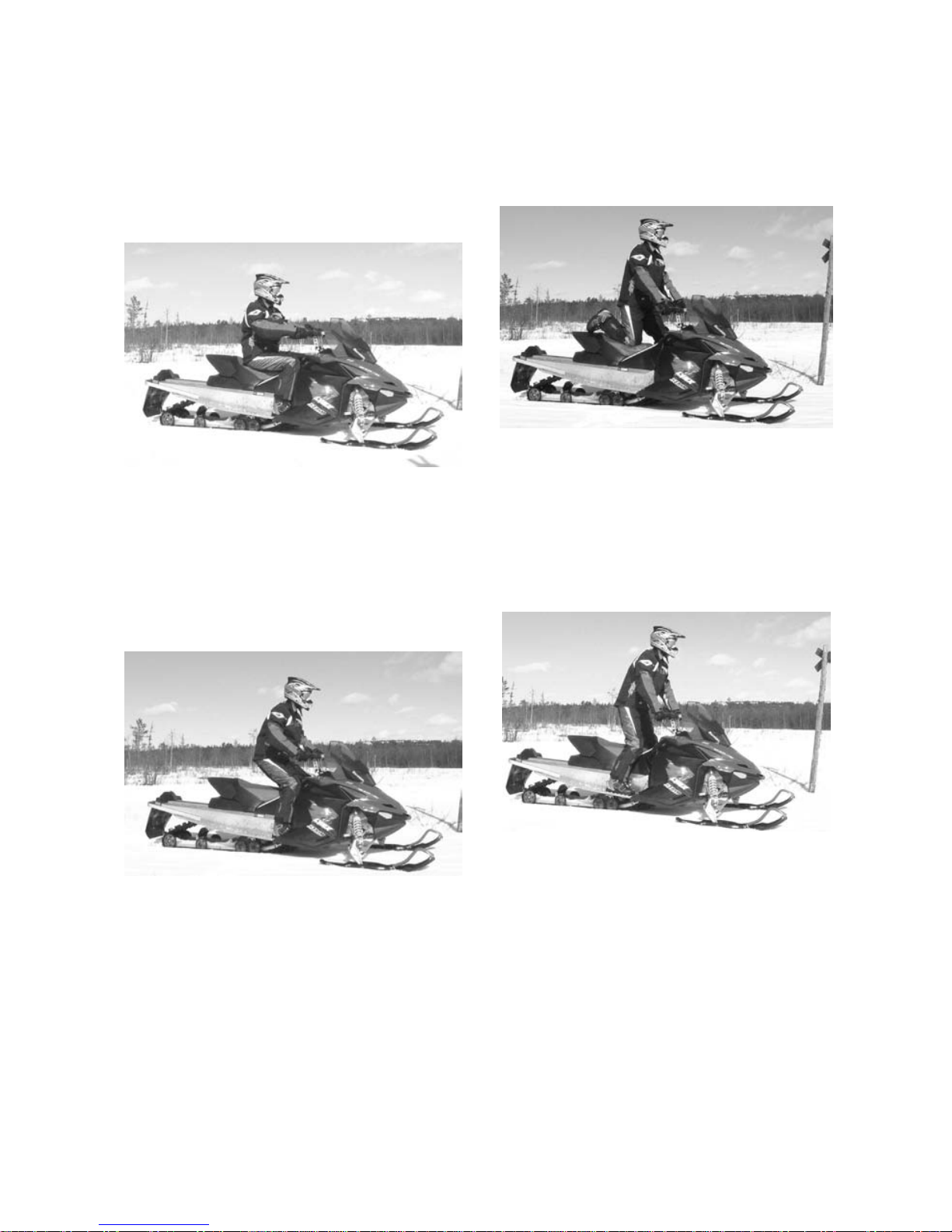
Sitting
Feet on the running boards, body midway back on seat is an ideal position
when operating the snowmobile over
familiar, smooth terrain. Knees and
hips should remain flexible to absorb
shocks.
Posting
A semi-sitting position with the body
off the seat and the feet under the
body in a so rt of squatting posture,
thus allowing the legs to absorb the
shocks when traveling over uneven
terrain. Avoid abrupt stops.
Kneeling
This position is achieved by placing
one foot firmly on the running board
and the opposite knee on the seat.
Avoid abrupt stops.
Standing
Place both feet on the running boards.
Knees should be flexed to absorb the
shock from surface bumps. This is
an effective position t o see be tte r and
to shift weight as conditions dictate.
Avoid abrupt stop.
Carrying a Passenger
Certain snowmobiles are designed for
an operator only, others can allow one
passenger only, and others can allow
up to two passengers. Refer to the
indications on the vehicles to know if
any particular snowmobile can accommodate passengers or not, and if so,
how many. Always respect those indications. Overloading is dangerous because snowmobiles are not designed
for it.
_____________________
15
Page 18

Even when passengers are allowed,
you must make sure that the persons
who would like to become passengers
are p h ysically fit for snowmobiling.
WARNING
Anypassengermustbeableto
firmly lay his feet on the footrests
andkeephishandsonthegrab
handles or seat strap at all times
when seated. Respecting those
physical criteria is important to
ensure that the passenger is stable
and to reduce the risks of ejection.
On snowmobiles allowing two passengers, if you have an adult and a
child for passenger, BRP recommends
that the child sits in the c enter location. This allows an adult s itting in the
rear seat to keep a visual contact with
the child and hold him if necessary.
In addition, the child is best protected
against the wind and cold temperature
if s eated in the center location.
Each operator has a responsibility to
ensure the safety of his passengers
and should inform them of snowmobiling basics.
WARNING
– Passengers must only sit on
designated passenger seats.
Never allow anyone to sit between the handlebar and the
operator.
– Each passenger seat must have
a strap or grab handles and
meet SSCC standards.
– Passengers and operators must
always wear DOT approved helmets and warm clothing appropriate for snowmobiling. Make
sure that no skin is exposed.
– Once underway, if a passenger
feels uncomfortable or unsecure for any reason, he must
not wait, and tell the driver to
slowdown or stop.
Riding with passen gers on board is
different than riding alone. The operator has the benefit of knowing what
will be the next maneuver and is able
to prepare himself accordingly. The
operator also benefits from the support of his grip on the handlebar. In
contrast, the passengers have to rely on the operator’s careful and safe
operation of the vehicle. In addition,
“body english” is limited with passengers, and the operator can sometimes
see more of the trail ahead than the
passengers. Therefore, smooth starting and stopping are required with
passengers, and the operator must
slow down. The operator must also
warn passengers of side h ills, bump s ,
branches, etc. An unforeseen bump
can leave you passenger-less. Remind your passengers to lean into
the turn with you, without causing
the vehicle to topple. Be extremely
careful, go more slowly and check the
passengers frequently.
WARNING
When riding with a passenger:
– Braking ability and steering
control are reduced. Decrease
speed and allow extra space to
maneuver.
– Adjust suspension according to
weight.
For complete inform ation on how
to adjust the suspension, please refer to the section of this Operator’s
Guide entitled SUSPENSION ADJUSTMENTS under OPERATING INSTRUCTIONS and to the relevant label on the
belt guard.
Use extra caution a nd go even more
slowly with young p as sengers. Check
frequently to make certain the child
has a firm g rip and is properly positioned with his feet on the running
boards.
16
______________________
Page 19

Terrain/Riding Variations
Groomed Trail
On a maintained trail, sitting is the
most preferred riding position. Do not
race and, above all, keep to the right
hand side of the trail. Be prepared
for the unexpected. Observe all trail
signs. Do not zigzag from one side of
the trail to the other.
Ungroomed Trail
Unless there has been a fresh snowfall you can expect “washboard” and
snowdrift conditions. Taken at excessive speeds, such conditions can be
physically harmful. Slow down. Hold
on the handlebar and assume a posting position. Feet should be under the
body assuming a crouched position to
absorb any jarring effect. On longer
stretches of “washboard” trails, the
kneeling position of one knee on the
seat can be adopted. This provides
a certain amount of comfort, while at
thesametimekeepsthebodyloose
and capable of vehicle control. Beware of hidden rocks or tree stumps
partially hidden by a recent snowfall.
Deep Snow
In deep “powder” snow, your vehicle
could begin to “bog” down. If this occurs,turninaswideanarcaspossible and look for a firmer base. If you
do get “bogged”, and it happens to
everyone, do not spin your track as
this makes the vehicle sink deeper. Instead, turn the engine off, get off and
move the back of the vehicle onto new
snow. Then tramp a clear path ahead
of the vehicle. A few feet will generally suffice. Restart the engine. Assume the standing position and rock
the vehicle gently as you steadily and
slowly apply the throttle. Depending
on whether the front or rear end of
the vehicle is sinking, your feet should
be placed on the opposing end of the
running boards. Ne ve r place foreign
material beneath the track for support.
Do not allow anyone to stand in front
of, or to the rear of, the snowmobile
with the engine running. Stay away
from the track. Personal injury will result if con tact is made with the revolving track.
_____________________
17
Page 20

Frozen Water
Traveling frozen lakes and rivers can
be fatal. Avoid waterwa ys. If you
are in an unfamiliar area, ask th e lo cal authorities or residents about the
ice condition, inlets, outlets, springs,
fast moving currents or other hazards. Never attempt to operate your
snowmobile on ice that may be too
weak to support you and the vehicle.
Operating a snowmobile on ice or icy
surfaces can be very dangerous if you
do not observe certain precautions.
Theverynatureoficeisforeignto
good control of a snowmobile or any
vehicle. Traction for starting, turn ing
or stopping is much less than that
on snow. Thus, these distances can
be multiplied manyfold. Steering is
minimal, and uncontrolled spins are
an ever present danger. When operating on ice, drive slowly with caution.
Allow yourself plenty of room for
stopping and turning. This is especially true at night.
Hard Packed Snow
Don't underestimate hard packed
snow. It can be difficult to negotiate
as both skis and track do not have as
much trac tion. Best advice is to slow
down and avoid rapid acceleration,
turning or braking.
Uphill
There are two types of hills you can encounter — the open hill on which there
are few trees, cliffs or other obstacles,
and a hill that can on ly be climbed directly. On an open hill, the approach
is to climb it by side hilling or slaloming. Approach at an angle. Adopt a
kneeling position. Keep your weight
on the uphill side at all times. Maintain a steady, safe speed. Continue
as far as you can in this direction, then
switch to an opposite hill angle and riding position.
A direct climb could present problems.
Choose the standing position, accelerate before you start the climb and
then reduce throttle pre ss ure to p re vent track slippage.
In either case, vehicle speed should
be as fast as the incline demands.
Always slow down as you reach the
crest. If you cannot proceed further,
don't spin your track. Turn the engine off, free the skis by pulling them
out and downhill, place the rear of the
snowmobile uphill restart the engine
and ease it out with slow even throttle
pressure. Position yourself to avoid
tipping over, then descend.
Downhill
Downhill driving requires that you
have full control of your vehicle at all
times. On s te e pe r hills, keep your
center of gravity low and both hands
on the handlebar. Maintain slight
throttle pressure and allow the machine to run downhill with the engine
operating. If a higher than safe speed
is reached, slow down by braking but
apply the brake with frequent light
pressure. Nev er jam the brake and
lock the track.
Side Hill
When crossing a side hill or traversing up or downhill, certain procedures
must be followed. All riders should
lean towards the slope as required
for stability. The preferre d operating
positions are the kneeling position,
with the knee of the down hill leg
on the seat and the foot of the uphill leg on the running board, or the
posting position. Be prepared to shift
your weight quickly as needed. Side
hills and s teep slopes are not recommended for a beginne r or a no vice
snowmobiler.
18
______________________
Page 21

Slush
Slush should be avoided at all times.
Always check for slush before starting across any lake or river. If dark
spots appear in your tracks, get off the
ice immediately. Ice and water can be
thrown rearward into the path of a following snowmobile. Getting a vehicle
out of a slush area is strenuous and in
some cases, impossible.
Fog or Whiteo uts
On land or water, fog or visibility-limiting snow can form. If you have to
proceed into the fog o r heavy snow,
do so slowly with your lights on and
watch intently for hazards. If you are
not sure of your way, do not proceed.
Keep a safe distance behind other
snowmobilers to improve visibility
and reaction tim e .
Unfamiliar Territory
Whenever you enter an area that is
new to you, drive with extreme caution. Go slow enough to recognize
potential hazards such as fences or
fence posts, brooks crossing your
path, rocks, sudden dips, guy wires
and countless other obstacles which
could result in a termination of your
snowmobile ride. Even when following existing tracks, be cautious.
Travel at a speed so you can see what
is around the next bend or over the
top of the hill.
Bright Sunshine
Bright sunny d ays can considerably reduce your vision. The glare from sun
andsnowmayblindyoutotheextent that you cannot e as ily distinguish
ravines, ditches or other obstacles.
Goggles with colored lenses should
always be worn under these conditions.
Unseen Obstruction
There may be obstructions hidden
beneath the snow. Driving off established t rails and in the woods requires
reducedspeedandincreasedvigilance. Driving too fast in an area can
make even minor obstacles very hazardous. Even hitting a small rock or
stump could throw your snowmobile out of control and cause injury to
its riders. Stay on established trails
to reduce your exposure to hazards.
Be safe, slow down and enjoy the
scenery.
Hidden W ires
Always be on the lookout for hidden
wires, especially in areas that may
have been farmed at one time or any
other. Too many accidents have been
caused by running into wires in the
fields, guy wires next to poles and
roads, and into chains and wires u sed
as road closures. Slow speeds are a
must.
Obstacles and Jumping
Unplanned jumps of snowdrifts,
snowplow ridges, culverts or indistinguishable objects can be dangerous.
You can avoid them by wearing the
proper color lenses or face shields and
by operating at a lower speed.
Jumping a snowmobile is an unsafe
and dangerous practice. However, if
the trail does suddenly drop away from
you, crouch (stand) towards the rear
ofthevehicleandkeeptheskisup
and straight ahead. Apply partial throttle and brace yourself for the impac t.
Knees must be flexed to act as shock
absorbers.
_____________________
19
Page 22
Turn i n g
Depending on terrain conditions, there
are two preferred ways to turn or corner a snowmobile. For most snow
surfaces, “body english” is the key to
turning. Leaning towards the inside of
the turn and positioning body weight
on the inside foot will create a “banking” condition beneath the track. By
adopting this po sition and positioning
yourself as far forward as possible,
weight will be transferred to the insid e
ski.
On occas ion, you will find that the only way to turn the vehicle about in
deep snow is to pull the snowmobile
around. Do not over-exert yourself.
Get assistance. Remember to alwa ys
lift using your legs as opposed to your
back.
Road Crossing
In some cases, you will be approaching the road from a ditch or snowbank.
Choose a place where you know you
can climb without difficulty. Use the
standing position and proceed with only as much speed needed to crest the
bank. Stop completely at the top of
the bank and wait for all traffic to clear.
Judge the drop to the roadway. Cross
the road at a 90° angle. If you encounter another snowbank on the opposite side, position your feet near the
rear of the vehicle . Remember, your
snowmobile is not designed to operate on bare pavement and steering on
this type of surface is more difficult.
Railroad Crossing
Never ride on railroad tracks. It is illegal. Railroad tracks and railroad rightsof-way a re private property. A snowmobile is no match for a train. When
crossing a railroad track, stop, look and
listen.
Night Rides
The amount of natural and artificial
light at a given time can effect your
ability to see or to be seen. Nighttime
snowmobiling is delightful. It can be
a unique experience if you acknowledge y ou r reduced visibility. Before
you start, make certain your lights
are clean and work properly. Drive
at speeds that will allow you to stop
in time when you see an unknown
or dangerous object ahead. Stay on
established trails and never operate in
unfamiliar territory. Avoid rivers and
lakes. Guy wires, barbed wire fences,
cabled road entrances and other objects such as tree limbs are difficult
to see at night. Never drive alone.
Always carry a flashlight. Keep aw ay
from residential areas and respect the
right of others to sleep.
20
______________________
Page 23

Safari Riding
Before starting out, designate a “trail
boss” to lead the party and another
person to follow-up at the end of the
party. Ensure that all members of the
party are aware of the proposed route
and destination. Make certain that
you are carrying all necessary tools
and equipment and that you have
sufficient fuel to complete the trip.
Never overtake the trail boss or, for
that matter, any other snowmobile.
Use down-the-line hand signals to indicate hazards or intent of direc tio n
change. Assist others whenever necessary.
ItisalwaysIMPORTANTtokeepa
safe distance between each snowmobile. Always maintain a safe interval
and allow sufficient stopping distance.
Don't be a tailgater. Know the position
of the machine ahead.
Signals
If you intend to stop, raise either hand
straight above your head. A left turn is
indicated by extending your left hand
straight out in the proper direction.
For right turns, extend the left arm and
raise t he hand to a vertical position so
it forms a right angle at the elbow. Every snowmobiler should relay any signal to the ones behind.
Trail Stops
Whenever possible, pull off the trail
when you stop. This will reduce the
hazard to other snowmobilers using
the trail.
Trails and Signs
Trail signs are used to control, direct
or regulate the use of snowmobiles on
trails. Become familiar with all signs
used in the area where you are snowmobiling.
Transporting and Towing
Follow transporting and towing instructions explained further in th is
guide.
_____________________
21
Page 24

22
______________________
Page 25

VEHICLE
INFORMATION
_____________________
23
Page 26
HOW TO IDENTIFY YOU SNOWMOBILE
Serial numbers
The main components of your snowmobile (engine and frame) are identified by different serial numbers. It
may sometimes become necessary
to locate these numbers for warranty
purposes or to trace your snowmobile
in the event of loss.
These numbers are required by the
Lynx dealers to complete warranty claims properly. No warranty will
be allowed by BRP if the engine serial
number or VIN is re moved or mutilated
in any way. We strongly recommend
that you take all the serial numbers on
your snowmobile and supply them to
your insurance com pany.
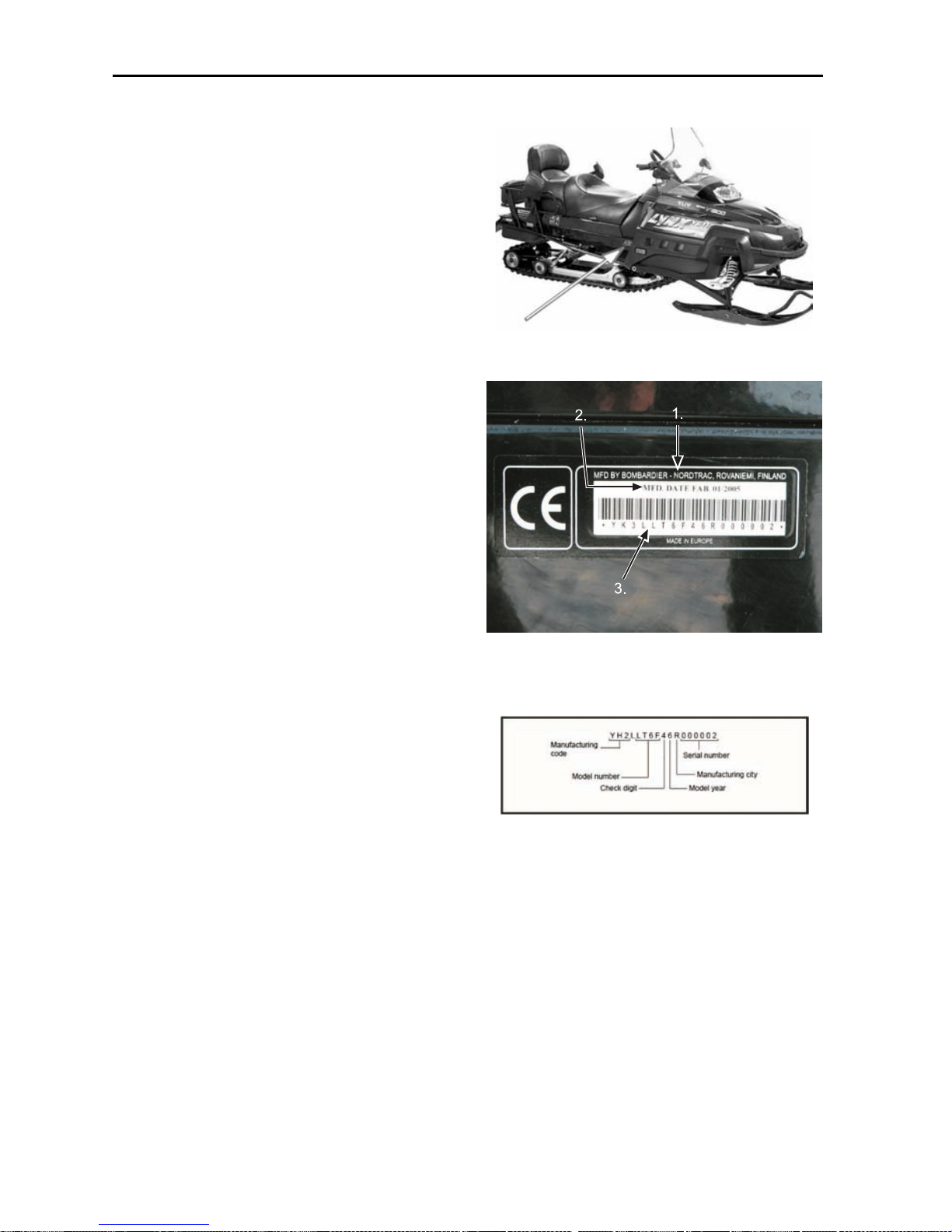
1. Vehicle description decal
1. Manufacturer name
2. Manufacturing date
3. Vehicle identification number (VIN)
VIN DESCRIPTION
24
______________________
Page 27

Engine serial number
1
A25C0MA
FAN CO OLE D
1. Engine serial number
LIQUID COOLED
1. Engine serial number
mmo2007-001-001_a
V-800
4–TEC MODELS
1. Engine serial number
_____________________
25
Page 28
CONTROLS/INSTRUMENTS
1) Throttle lever
Located on the right side of handlebar.
When compressed, it co ntro ls the engine speed and the engagement of the
transmission. When released, engine
speed returns automatically to idle.
1. Throttle lever
2) Brake lever
Located on the left side of handlebar.
When compressed, the brake is applied. Whe n released, it automatically
returns to its o riginal position . Braking
effect is proportional to the pressure
appliedontheleverandtothetypeof
terrain and its snow coverage.
1. Brake lever
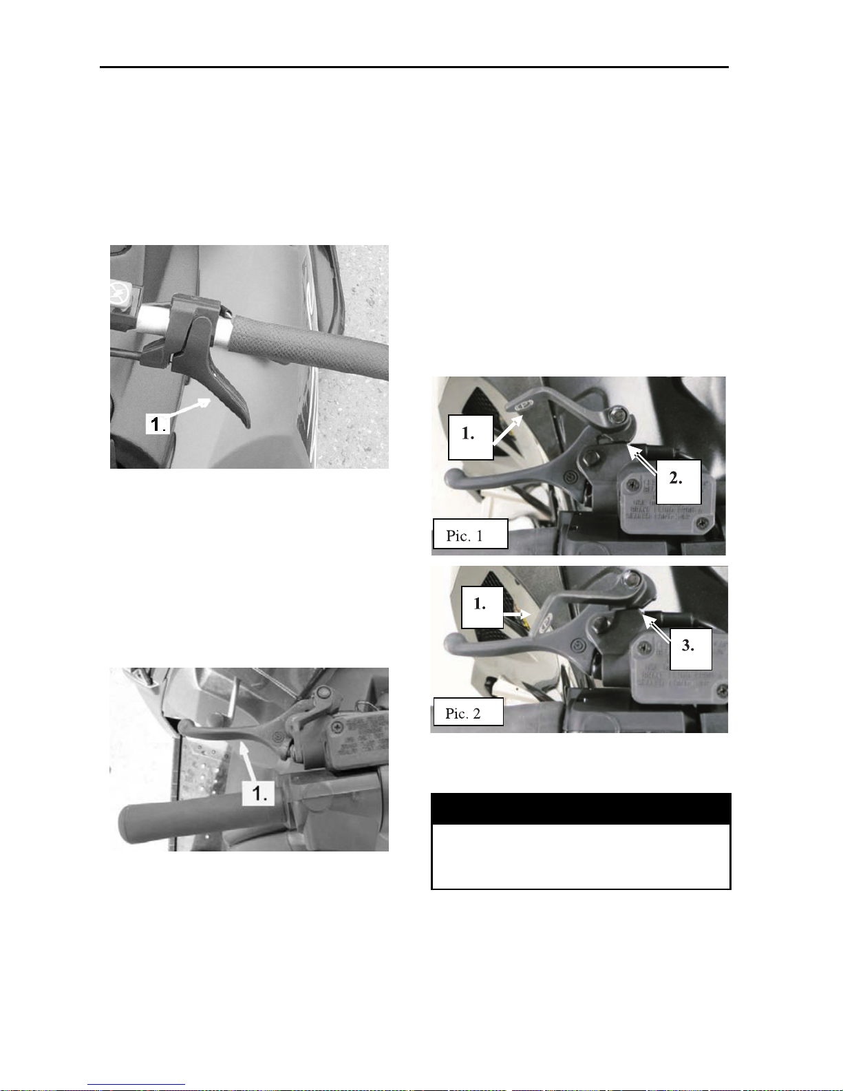
3) Parking brake button
or lever
Hydraulic brake
Located on left side of handlebar.
Parking brake should be used whenever snowmobile is parked.
Whenever parking brake is applied
and engine is runn ing, injection oil level/parking brake pilot lamp lights up to
remind you that it is engaged. Never
leave your snowmobile on downhill
only with parking brake engaged.
1. Locking lever
2. Position 1
3. Position 2
WARNING
Make sure parking brake is fully
disengaged before operating the
snowmobile.
26
______________________
Page 29
WARNING
Locking keeps brake lever engaged
and keeps pressure against brake
disc.
Anyhow, this pressure may decrease so low, that it w ill not keep
vehicle in place. Never leave the
snowmobile on hill only with parking brake applied.
4) Pilot Lamps
Reverse (Red)
This pilot lamp will light up
when reverse is selected.
DESS Status (Red)
This lamp will light up to
confirm DESS status. Refer
to previous paragraphs for
description.
High Beam (Blue)
Lights when headlamp is on
HIGH beam.
Engine Overheat Warning (Red)
If this lamp glows, reduce
snowmobile speed and run
snowmobile in lo ose snow or
stop engine immediately.
Low Battery Voltage (Red)
This lamp will light up to
indicate a low battery voltage
condition. See an authorized
Lynx dealer as soon as
possible.
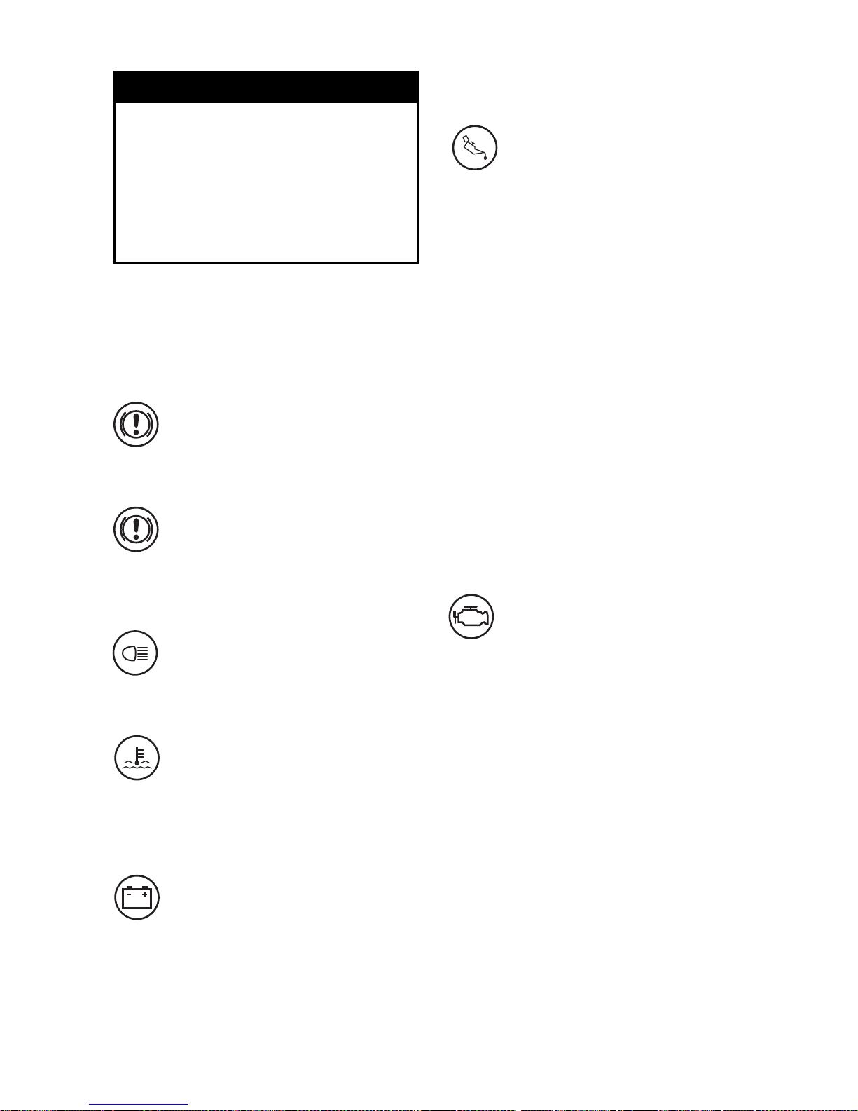
Injection Oil Level/Engine
Oil Pressure
Yeti 2-stroke models
This pilot lamp will glow up when injection oil leve l is low. Stop vehicle in
a safe plac e then, replenish in jection
oil reservoir.
V-800 Series
This pilot lamp will glow up when engine oil pressure is too low. Stop vehicle in a safe place then, check oil level
and replenish as described in ENGINE
OIL LEVEL.
Restartengine,oilpilotlampmustturn
off after few seconds. If oil pilot lamp
still glows up, stop engine and have lubrication system inspected by an authorized Lynx dealer.
Engine Management System
(EMS) (Red)
This lamp will light up to
indicate a trouble. Refer
to TROUBLESHOOTING for
trouble code meaning and
remedy.
_____________________
27
Page 30
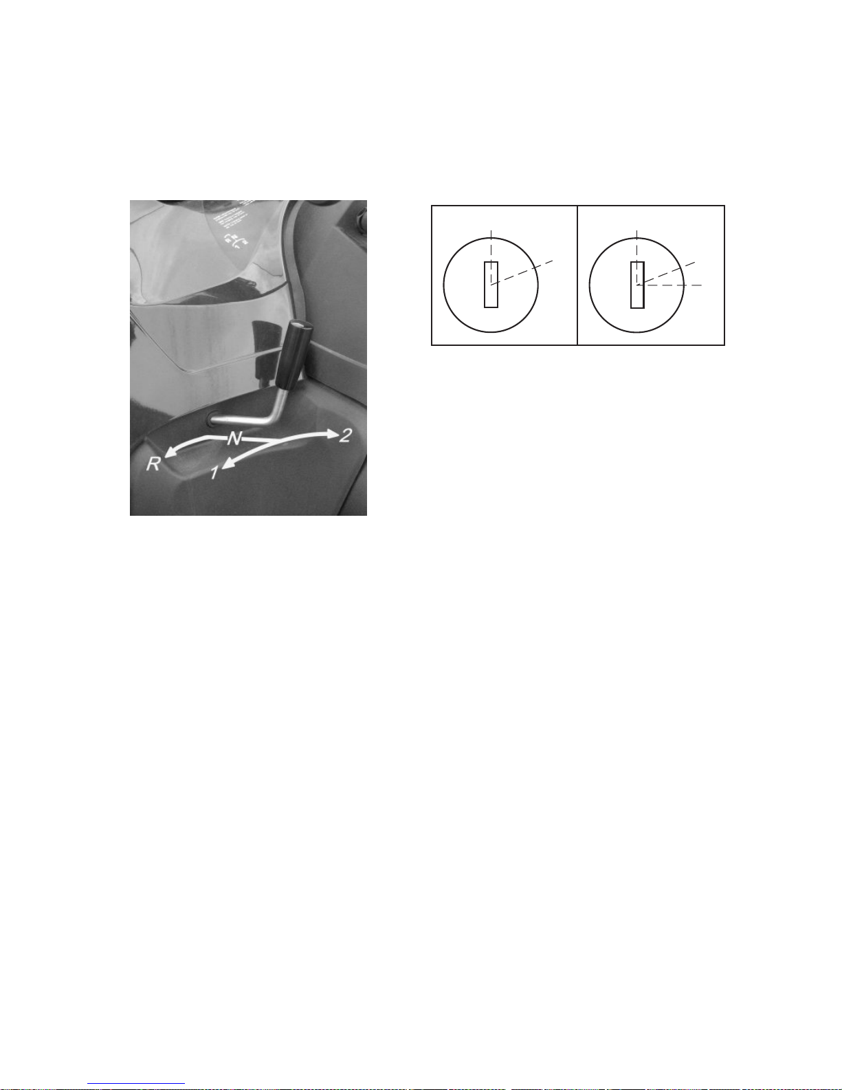
5) Gear shift lever
Gear box models: These models are
equipped w ith 4-position gear shift
lever; 2 gears forward, reverse gear
and free position between 1. and 2.
gear.
Shifting procedure
NOTE: Shift the gear only when engine is running at idle and the speed
is below 20 km/h.
Come to complete stop before selecting reverse gear. Do not force leve r. If
unable to shift, apply throttle to move
snowmobile. Stop vehicle, the n try
again.
NOTE: These models: Whenever
shifting the gear the snowmobile has
to be completely stopped, otherwise
the gear system may get broken.
6) Handlebar
The handlebar controls the steering
of the snowmobile. As the handlebar is rotated to right or left, the skis
are turned right or left to steer the
snowmobile. Handlebar height is adjustable. See an authorized Lynx dealer.
7) Holding strap
Holding strap provides a grip for driver
when side-hilling .
8) Ignition switch /
START button
1 1
2
2
3
A23H04A
MANUAL START/ELECTRIC START MODELS
1. OFF
2. ON
3. START
Manual Starting
To start the engine, turn the key to ON
position, then pull rewind starter grip,
To stop the engine, turn the key to OFF
position.
Electric Starting
To start engine, turn key to START position and hold until engine has started. See illustration above.
NOTE: Do not use electric starter for
more than 15 seconds. If start/rer
button is pressed when engine has
started it could damage electric starter
mechanism.
Release key as soon as the engine
starts. Key returns to ON position as
soon as it is rele ased.
If engine does not start on first try, turn
key back to OFF position and wait a
few seconds before restarting.
To stop engine, turn key to OFF position.
NOTE: Engine may be manually started with rewind starter if necessary.
If starter does not operate, check starting system fuse condition. re fer to
FUSES.
28
______________________
Page 31

Start Mode
To start engine, push START button
and hold until engine has started.
NOTE: Do not hold START button
more than 10 seconds. A rest period should be observed between
the cranking cycles to let starter cool
down. Holding START button when
engine has started could damage
starter mechanism.
9) Tether cut-out switch
It shuts off engine preventing snowmobile to runaway if the operator falls
off the vehicle accidently.
Operation
Attach to clothing eyelet than snap
tether cord cap over post before starting engine.
1. Snap over post
2. Attach to eyelet
If emergency engine shut off is required, completely pull tether cord cap
from post.
TYPICAL
Some Liquid-Cooled Models
On these models tether cut out switch
is part of tether cut out system. This
system serves 3 functions. It shuts
off engine preventing snowmobile to
runaway if the operator falls off the
vehicle accidently.
Through the D.E.S.S.
TM
(Digitally Encoded Security System), it acts as a
lock by preventing unauthorized use of
your snowmobile thus deterring theft.
Finally, it prevents unintentional electric starter operation in vehicles so
equipped by disabling the electric
starter and ignition circuits in the
MPEM or ECU.
DESS (Digitally Encoded
Security System) Description
This system is digitally encoded to provide you and your snowmobile with
the equivalent security as a conventional lock key.
The tether cord cap provided with
your snowmobile contains an electronic chip in which a unique digital
code is permanently memorized. Your
authorized Lynx dealer program s this
key code in the MPEM or ECU of your
snowmobile to allow engine operationabove3000RPMifandonlyif
this unique code has been read after
engine starting.
If a tether cord cap with different code
is installed, the engine will start but
cannot reach drive pulley engagement
speed to move vehicle.
Additional Tether Cord Caps
The MPEM/ECU of your snowmobile
canbeprogrammedbyyourauthorized Lynx dealer to accept 8 different
key codes (tether cord caps).
DESS Pilot Lamp Codes
DESS pilot lamp blinking slowly (one
time per 1,5 second) means that a bad
connection has been detected. Vehicle can not be driven.
_____________________
29
Page 32

To check for bad connection, remove
tether cord cap. Make sure the tether
cordcapisfreeofdirtorsnow. Reinstall cap and restart engine. If a blink
still occurs, contact an authorized dealer.
1. Free of dirt and snow
A DESS pilot lamp blinking 3 times per
second means that y ou have installed
a cap with a code that MPEM of this
snowmobile was not programmed to
recognize (wrong key). Vehicle can
not be driven.
10) DESS pilot lamp
This lamp will light up to co nfirm DESS
status. Refer to previous paragraphs
for description.
11) Engine cut-out switch
This push-pull type or toggle type
switch is located on the right side of
the handlebar. To stop the engine in
an emergency, se le ct O FF p osition
and simultaneously apply the brake.
To restart, button must be at the ON
position.
1. ON
2. OFF
All operators of the snowmobile
should familiarize themselves with
the function of this device by using it several times on first outing
and whenever stopping the engine
there-after. This engine cut-out procedure will become a reflex and will
prepare operators for emergency situations requiring its use.
30
______________________
Page 33

12) Electric horn
Electric horn button is located on left
hand side of handlebar
Yeti pro v-800 (EU) model only
1. Electric horn button
13) Headlamp dimmer
switch
Located on left hand side of handlebar,
allows selection of headlamp be am.
Note that lights are automatically ON
whenever the engine is running.
Yeti models
14) Rewind starter handle
Yeti 550 models
Auto-rewind type located on right
hand side of snowmobile. Pull handle
slowly until a resistance is felt then
pull vigorously. Slowly release handle.
15) Choke lever
Yeti 550 models
1. OFF
2. Position 1
3. Position 2
Initial Cold Starting
NOTE: Do not operate the throttle
lever with the choke lever on.
Movethechokelevertoposition2and
start the engine. As soon as the engine starts move the lever to position
1. After a few seconds (10 seconds
maximum) move the choke lever to
position OFF.
NOTE: In severe cold weather, colder
than - 20°C you m ay need to flip choke
lever from OFF position to position 1 a
couple of times once engine is started.
Warm engine starting
Start the engine without any choke.
If the engine will not start after two
pulls of the rope or two 5 second attempts with the electric starter move
choke lever to position 1. Start the
engine without activating t he throttle
lever. As s oon as the engine starts
move the choke lever to OFF.
16) Odometer
Odometer reco rds the total distance
travelled in kilometers. It can be reset
when needed.
17) Trip meter
Records the distance travelled. It can
be reset when needed.
_____________________
31
Page 34

18) Trip meter reset button
To reset the meter, push the button
until all the numbers are zero (0).
AllYetimodels: These models are
equipped with electronic speedometer. It shows the sp eed either in kilometers or miles per hour.
1. Mode button
2. Engine Management System (EMS)
pilot lamp
3. Oil pressure pilot lamp
4. Cooling liquid pilot lam p
5. High beam pilot lamp
6. Battery charge pilot lamp
7. Brake pilot lamp
Electronic speed- and
tachometer
Records total distance travelled until it
is reset.
Mode button
Depress the mode button to change
display. Each time engine is started,
display s hows odometer. From that
point depressing mode button again to
return the odometer.
Depressing mode button again will
change display for the resetable
hourmeter. Push mo de button again
to return to odometer.
Pushandholdmodebuttonfor2secondstoresetthetripmeterortheresetable hourmeter depending on the
one displayed.
Odometer
Odometer reco rds the total distance
travelled and display it in kilometers.
Trip Meter
Records distance travelled since it has
been reset. Distance travelled is displayed in kilom eters.
Resettable hour meter
Records engine running time in hours
and minutes since it has been reset.
All models: Pushandholdmode
button for 2 seconds to reset the resetable hour meter.
Electronic display code
If your speedometer shows “SCALE”
in the display, it means that the disp lay
selector button is stuck in the down
position or depressed when the electrical system was activated.
Some models: At vehicle speed of
90 km/h and more the mode LCD
screen will show s peed only instead
of the selected mode.
NOTE: At the electronic speedometer
display appears “9-9” when you power up the vehicle. This means that the
speedometer is calibrated to 9 teethed
drive sprocket.
19) Fuel tank cap/gauge
Unscrew to fill up tank then fully tighten. Fuel tank cap features a mechanical gauge .
Located at rear of fuel tank cap the
gauge facilitates fuel level reading.
32
______________________
Page 35

1. Full
2. Empty
WARNING
Always stop the engine before refueling. Fuel is flammable and explosive under certain conditions.
Always work in a well ventilated
area. Do not smoke or allow open
flames or sparks in the vicinity.
Open cap slow ly. If a differential pressure condition is noticed
(whistling sound heard when loosening fuel tank cap) have vehicle
inspected and/or repaired before
further operation. Do not overfill or top off the fuel tank before
placing the vehicle in a warm area.
As temperature increases, fuel
expands and might overflow. Always wipe off any fuel spillage
from the vehicle. Periodically verify fuel system.
NOTE: Do not sit or lean on seat when
fuel tank cap is not properly installed.
20)Heatinggripswitch
It is a three–position switch. Select
the desired position to keep your
hands at a c omfortable temperature.
YETI MODELS
1. Heated grip switch
2. Heated throttle lever switch
3. Hot
4. Warm
5. OFF
21) Heated throttle lever
switch
Three-position switch. Select the desiredpositiontokeepyourrightthumb
at a comfortable temperature. Se e illustration.
Rear passengers heated
grip switches
Three-position switch. Select the desired position to keep rear passenger’s
hands at comfortable temperature.
22) Hood latches
Stretch and unhook the latches to unlock the hood from its anchors. Lift
hood gently until stopped by retaining
device. Close hood slowly then hook
up latches.
23) Power outlet
A 12-volt electric appliance may be
connected to the jack connector. Electric current is supplied when ever engine is running. See FUSES for electric power outlet fuse location.
_____________________
33
Page 36

MODELS
MAXIMUM
OUTPUT
CURRENT
LOCATION
20 amperes Rear rack
Yet i Pr o
V800
5 amperes
Dashboard
All others
5 amperes
Dashboard
A29I04A
TYPICAL — ELECTRIC POWER OUTLET
Yeti pro v-800 Model Only
With the engine running, use the
toggle switch mounted on the multiswitch housing to supply current to
the rear rack power outlet.
mmo2008-001-017_a
MULTI-SWITCH HOUSING
1. Rear power outlet switch
2. Upper/Lower ON position
3. Middle OFF position
mmo2008-001-016_a
YETI PRO V-800 MODEL ONLY — REA R RACK
22. Electric power outlet
24) Fuse
To remove fuse from holder, pull fuse
out. Check if filam e nt is melted .
1. Fuse
2. Check i f melted
Fuse for starting system and
electric power outlet
Starting system and electric power
outlet is protected (if equipped) with
20 ampere fuse. If the starter and
electric power outlet is out of function, check the fuse condition and
replace if needed.
NOTE: Donotuseahigherratedfuse
as this can c ause sev ere damage to
electric components and/or fire.
Yet i m odel s To open fuse box push on
cover tab and tilt cover.
34
______________________
Page 37

1. Push tab
1. Fuse description decal
2. Fuse remover/installer
3. Spare fuses
1. Fuse remover/installer
25) Tool kit
A tool kit containing tools for basic
maintenance is supplied with the engine. Tool bag is located under the
seat or hood.
26) Front grab handle/front
bumper
To be used whenever front of snowmobile requires manual lifting.
1. Front grab handles
NOTE: Do not use skis to pull or lift
snowmobile.
27) Storage compartment
Depending on model, storage compartment situates either under the
seat or inside of the seat.
1. Open latch
28) Rear rack
Yeti models: Always readjust suspension according to the load. The
capacity of this rack is limited.[Max
20 kg] Ride at very low speed when
loaded. Avoid speed over bumps.
_____________________
35
Page 38

29) Hitch
Thehitchcanbeusedtopullmost
equipment. Use a rigid tow bar.
NOTE: Remember to lock the hitch
locking latch with a lock pin.
Following picture shows how much
load is allowe d and to transpo rt and to
pull. This decal is found at end of rear
racket on your own vehicle.
30) Modular Seat
Yeti models
Those models can be converted into a
snowmobile with one (1) seat only instead of two (2). This could be useful
if you want to increase the cargo area.
2
1
TYPICAL
1. Passenger seat (removable)
2. Driver seat
To remove the passenger seat, lift seat
latch, then tip driver seat over.
1
2
TYPICAL
1. Seat latch
2. Tipdriverseatover
Slide the passenger seat forward, then
lift to remove.
CAUTION: On models equipped
with passenger seat grab handles,
unplug the heated grips connector before removing the passenger
seat.
2
3
1
TYPICAL
1. Passenger seat
2. Slide seat forward
3. Lift seat to remove
CAUTION: Take care to store the
passenger seat properly to avoid
any dam ages.
WARNING
NEVERcarryapassengerifthe
backrest is not installed properly
36
______________________
Page 39

WARNING
NEVER use the hole left by removing the passenger seat to sit a passenger. The passenger could hurt
his back or suffer other serious injuries due to his seating position.
WARNING
All objects in rear rack must be
properly latched. Do not carry
any breakable objects. Excessive
weight in rack may reduce steering ability.
Installation is the reverse of removal
procedure. Pay attention to the following.
WARNING
Make sure that the passenger seat
is locked securely in place bef ore
using the snowmobile.
1
TYPICAL
1. Passenger seat hooks
31) Rear Grab Handles/
HeatingGripSwitch
mmo2007-001-018_a
1. Left side passenger grab handle
2. Heatinggripswitch
Rear Grab Handles
Rear grab handles provides a grip for
the passenger.
Heating Grip Sw itch
Three-position switch. Select the desired position to keep rear passenger's
hands at a c omfortable temperature.
_____________________
37
Page 40

32) Adjustable suspension
1. Rear Springs — Comfort
IMPORTANT: Make sure that all objects to be transported are in place in
rear rack and under the seat.
• Grab rear bumper and lift until suspension is fully extended.
• From this point, rear of snowmobile
shouldcollapseby50to75mm(2
to 3 in) when driver, passenger (if so
applicable) and load take place.
• Measure at rear bum per as shown
in next illustration.
WARNING
Do not attempt to lift the vehicle
by hand alone. Use appropriate
lifting device or have assistance
to share lifting stress in order to
avoidriskofstraininjuries.
Rear Springs Adjustment
C
B
A
mmo2006-003-022_a
TYPICAL — PRO PE R ADJUSTMENT
A. Suspension fully extended
B. Suspension has collapse with driver,
passenger and load added
C. Distance between dimension A and B, must
notexceed50to75mm(2to3in),seetable
REAR SPRINGS ADJUSTMENT
”C” CAUSE SOLUTION
50 to 75 mm
(2 to 3 in)
No adjustment required
More than
75 mm (3 in)
Adjustment
too soft
Increase
preload
Less than
50 mm (2 in)
Adjustment
too hard
Decrease
preload
Increase S pring Preload
Yeti models with Easy ride
XWLS suspension
CAUTION: To increase preload, always turn the left side adjustment
cam in a clockwise direction, and
the right side cam in a counterclockwise direction. Left and right adjustment cams may be at different
settings.
mmo2008-001-006_a
TYPICAL
1. Adjustment cam
2. Turn to increase spring preload
Yeti models with RCG-A
suspension
From the lowest position, turn adjuster to select highest position, then
turn adjuster to the desired position.
38
______________________
Page 41

mmo2008-001-005_a
TYPICAL
1. Pull on handle
2. Turn to increase spring preload
Decrease Spring Pre lo a d
Yeti models with Easy ride
XWLS suspension
CAUTION: To decrease preload,
always turn the left side adjustment cam in a counterclockwise
direction, the right side cam in a
clockwise direction. Left and right
adjustment cams may be at different settings.
mmo2008-001-006_a
1. Pull on handle
2. Turn to decrease spring preload
Yeti models with RCG-A
suspension
mmo2008-001-005_a
TYPICAL
1. Pull on handle
2. Turn to decrease spring preload
2. Suspended Extension
Adjustment
Suspended extension can be adjusted
according to the load and snow conditions.
For better deep snow performance
or to increase reverse performance in
deep snow, first loosen lock nut, then
tighten nut 3/4 turn after contacting
washers. Retighten lock nut. Adjust
thesameonbothsides.
For trail riding with a load or for pulling
a load, first loosen lock nut. Turn to
a maximum preload of 3 turns after
nut touching washers. Retighten lock
nut. Adjust the same on both sides.
3. Shackle Movement Limiter
For deep snow riding, do not install
horse shoe washers.
For trail riding with passenger and/or
weight, install 1 horse shoe washer
under each rubber stoppers.
For trail riding with heavy load and/or
pulling a load, use 2 horse shoe washers under each rubber stoppers.
CAUTION: Always install same
amount of washers on both sides.
_____________________
39
Page 42

1
23
A29F03A
1. Horse shoe washer(s)
2. Nut
3. Lock nut
4. Center Spring — Steering
Behavior
Yeti models with RCG-A
suspension
• Ride at moderate s peed on a trail.
• If handlebar is felt too easy or too
hard to turn, adjust center spring
accordingly.
WARNING
Before proceeding w ith any suspension adjustment , remember:
– Park in a safe place.
– Remove tether cord cap.
– Lift rear of vehicle of f the
ground with suitable lifting device.
– Make sure lifting device is stable
and secure.
CENTER SPRING ADJUSTMENT
HANDLEBAR
(steering
attitude)
PROBLEM SOLUTION
Easy to turn
(neutral)
No adjustment required
Harder to turn
(oversteering)
Adjustment
too soft
Increase
preload
Very easy
to turn
(understeering)
Adjustment
too hard
Decrease
preload
Increase S pring Preload
A29F0DA
1
1. Use adjuster w rench provided in tool
kit to increase preload
Decrease Spring Pre lo a d
A29F0DB
1
1. Use adjuster w rench provided in tool
kit to decrease preload
40
______________________
Page 43

5. Stopper Strap — Weight
Transfer
• Ride at low speed, then fully accelerate.
• Notesteeringbehavior.
• Adjust stopper strap length accordingly.
CAUTION: Whenever stopper strap
length is changed, track tension
must be readjusted.
WARNING
Before proceeding w ith any suspension adjustment , remember:
– Park in a safe place.
– Remove DESS key or tether cord
cap.
– Lift rear of vehicle of f the
ground with suitable lifting device.
– Make sure lifting device is stable
and secure.
STOPPER STRAP
WEIGHT TRANSFER ADJUSTMENTS
STEERING
TRACK
(skis)
PROBLEM SOLUTION
Comfortable
Good weight
transfer
(light pressure)
No adjustment required
Light
Too mu ch
weight transfer
(lift off the
ground)
Strap too
long
Reduce
strap length
Heavy
Not enough
weight transfer
(heavy pressure)
Strap too
short
Increase
strap length
Strap Length Adjustment
Yeti models with Easy ride
XWLS suspension
A29F06B
1
1. Screw or unscrew knob to vary strap length
_____________________
41
Page 44

Yeti models with RCG-A
suspension
1
A29F0FA
1. Bolt stopper strap to a different hole
6. Front Suspension S prings —
Handling
• Ride at moderate speed and check
for proper handling.
• Adjust front springs accordingly.
WARNING
Before proceeding w ith any suspension adjustment , remember:
– Park in a safe place.
– Remove tether cord cap.
– Lift rear of vehicle of f the
ground with suitable lifting device.
– Make sure lifting device is stable
and secure.
WARNING
Always adjust both front springs to
same position.
FRONT SPRINGS ADJUSTMENT
HANDLING
(steering)
PROBLEM SOLUTION
Good
(comfortable)
No adjustment required
Bad
(too easy to turn)
Adjustment
too soft
Increase sprin g
preload
Bad
(hard to turn)
Adjustment
too hard
Decrease
spring preload
Increase Spring Preaload
A29F0EA
1
1. Increase spring preload
Decrease Spring Pre lo a d
A29F0EB
1
1. Decrease spring preload
42
______________________
Page 45

SUSPENSION TROUBLESHOOT
PROBLEM CORRECTIVE MEASURES
Front suspension wandering.
– Check ski alignment and camber angle
adjustment. See an authorized Lynx dealer
– Reduce ski ground pressure.
– Reduce front suspension spring preload.
– Increase center spring preload.
– Reduce rear spring preload.
Snowmobile seems unstable and
seems to pivot around its centre.
– Reduce rear suspension front arm pressure.
– Reduce center spring preload.
– Increase rear spring preload.
– Increase front suspension spring preload.
Steering feels to heavy.
– Reduce ski ground pressure.
– Reduce front suspension spring preload.
– Increase center spring preload.
Rear of snowmobile seems to stiff.
– Reduce rear spring preload.
Rear of snowmobile seems to soft.
– Increase rear spring preload.
Rear suspen sion front sh ock
absorber is frequently bottoming.
– Lengthen stopper strap.
– Increase center shock preload.
Track spins too much at start.
– Lengthen stopper strap.
– Change driving position.
In deep snow
When operating the snowmobile in deep snow, it may be necessary to vary extension adjustm ent, stopper strap and/or riding position, to change the angle at
which the track ride s on the snow. Operator’s familiarity with the various adjustments as well as snow conditions will dictate the most efficient combination.
_____________________
43
Page 46

FUEL AND OIL
Recommended fuel
Refer to TECHNICAL DATA in the end
of this manual.
NOTE: Never experiment with other
fuels or fuel rations. The use of unrecommended fuel can result in snowmobile performance deterioration and
damage to critical parts in the fuel system and engine components.
WARNING
Do not overfill or top off the fuel
tank before placing the vehicle in
a warm area. As temperature increases, fuel expands and might
overflow. Fuel is inflammable and
explosive under certain conditions. Wipe off any fuel spillage
from the vehicle.
Fuel System Antifreeze
When using oxyge nated fuel, additional gas line antifreeze or water
absorbing additives are not required
and should not be used.
Recommended oil
2-tec models: Use BRP Synthetic
Blend 2-stroke injection oil (P/N 293
600 071) or BRP Syn thetic 2-stroke
injection oil (P/N 293 600 045) or BRP
Mineral 2-stroke injection oil (P/N 413
803 000).
CAUTION: Do not mismatch oil
reservoir cap with fuel tank cap. On
some models there is fuel gauge
together with fuel tank cap. Oil
reservoir cap is identified “OIL”.
Use only oil, which flows at -40°.
Oil is in injection oil reservoir.
Useonly2-strokeengineoil.
CAUTION: Never use four-stroke
mineral or synthetic oil. Do not
mix these with outboard motor oil.
Do no use NMMA TC-W, TC-W2 or
TC-W3 outboard oil. Avoid mixing
different brands of API TC oil as
resulting chemica l reactions may
cause severe engine damage.
Always maintain a sufficient amount
of recommended oil in the injection oil
reservoir.
CAUTION: Check level and refill every time you refuel. Do not mismatch oil reservoir cap with fuel
tank cap. Install cap that is identified with OIL
4-tec models: These models are
equipped with 4-stroke engine. Use
Bombardier 4-stroke synthetic oil 0W
40 or fully synthetic equivalent oil.
Gear box oil
Recommendation 75W140.
Cold weather carburetion
modifications
All vehicles has been calibrated for
-20°C. They can be operated at
warmer winter temperatures without problems.
CAUTION: Forcoldertemperatures
than - 20°C, carburetor(s) must be
recalibrated to avoid engine damage. Refer to an authorized Lynx
dealer.
44
______________________
Page 47

BREAK-IN PERIOD
Engine
IMPORTANT: A break-in period of
10-15 hours (about 500 km) is required
for Rotax engines before running the
snowmobile at full throttle.
During break-in period, maximum
throttle should not exceed ¾ . However, brief full acceleration and
speed variations contribute to a good
break-in.
All models except 4-tec and 2-tec
SDI models: To assure additional pro-
tection during the initial en gine breakin, 500 ml of recommended injection
oil should be added to fuel for the first
full filling of fuel tan k.
Have spark plugs cleaned after engine
break-in.
Drive Belt
A new drive belt requires a break-in period of 50 km. Avoid strong acceleration/deceleration, pulling a load or high
speed cruising
10 Hour Inspection
We suggest that after the first 10
hours of operation— 500 km — or
30 days after the purchase, whichever comes first, your snowmobile be
checked by an authorized Lynx dealer.
NOTE: The 10 hour inspection is at
expense of the snowmobile owner.
_____________________
45
Page 48

PRE OPERATION CHECKLIST
• Remove snow and ice from body including seat, footrests, lights, controls and instruments.
• Verify that track and idler wheels
are not frozen and free to turn.
• Activate t he brake control and make
sure the brake fully applies bef ore
the brake control lever touches the
handlebar grip. It must fully return
when released.
• Check the parking device. Apply
parking brake and check if it operates easily and smoothly.
• Activate the throttle control lever
several times to check that it operates easily and smoothly.
• Check operation of ignition switch,
head lamp switch, taillight, brake
light, pilot lamps and tether/cut-out
switches.
• Verify that skis a nd steering operate
freely. Check corresponding action
of skis versus handlebar.
• Check fuel and injection oil for levels and leaks. Replenish as necessary and see an authorized Lynx
dealer in case of any leaks.
• Verify that air filter(s) is fre e of
snow, if so equipped.
• Make certain your snowmobile is
pointed away from people or objects before you start it.
• Be warmly dressed with clothing
designed for snowmobiling.
46
______________________
Page 49

OPERATING INSTRUCTIONS
Propulsion
Depressing throttle lever increases
engine RPM ca using the drive pulley
to engage. Depending on models engine RPM must be between 2500 and
4200 before drive pulley engagement
will occur.
Outer sheave of drive pulley moves
toward inner sheave, forcing drive
belt to move upward on the drive
pulley and simultaneously forcing the
sheaves apart on the driven pulley.
The driven pulley senses the load on
the track and limits the belt movement. The result is an optimized
speed ratio between engine RPM and
the speed of the vehicle at any time.
Power is transferred to the track
through the chaincase or gearbox
and drive axle.
Turni ng
Handlebar controls the steering of the
vehicle. As the handlebar is rotated to
right or left, the skis are turned right or
left to steer the snowmobile.
Stopping
Before riding your snowmobile, you
should understand how to stop it.
This is done by releasing the throttle
and gradually depressing the brake
lever on the left side of the handlebar.
In an emergency, you may stop your
vehicle by pressing the engine cut-out
switch located near the throttle control
and applying the brake.
Remember, a snowmobile cannot
”stop on a dime”. Braking characteristics vary with deep snow, packed
snow or ice. If the track is locked duringhardbraking,skiddingmayresult.
Starting the engine
Check throttle lever operation.
Ensure that the engine cut out switch
is in the ON position.
Ensure that the tether cord cap is in
position and that the cord is attached
to your clothing eyelet.
Choke equipped vehicles
Initial cold starting: Do not operate
the throttle lever with the choke lever
on.
When temperature is below - 10°C
Movethechokelevertoposition2and
start the engine. As soon as the engine starts move the lever to position
1. After a few seconds (max.10 seconds) move the choke lever to OFF position.
NOTE: In severe cold weather, colder
than - 20°C you m ay need to flip choke
lever from OFF to position 1 a couple
of times once engine is started.
1. OFF
2. Position 1
3. Position 2
When temperature is above - 10°C
Move the choke lever to position 1.
Grab the handle firmly and start the en-
gine or electric starter if it is equipped.
As soon as the engine starts move the
choke lever to OFF.
4-tec models
Initial cold starting and warm
engine starting
Use the electric starter.
_____________________
47
Page 50

CAUTION: 4-tec models: If the battery is empty, engine cannot be
started. Charge the battery or replaceitifnecessary.
Warm engine starting
Start the engine without any choke.
If the engine will not start after two
pulls of the rope or two 5 second attempts with the electric starter move
choke lever to position 1. Start the
engine without activating the throttle
lever. As s oon as the engine starts
move the choke lever to OFF.
Electrical starting (if so equipped)
– Depressing the START-button will
engage the electric starter and start
the engine.
– Release button immediately when
engine has started.
WARNING
Do not apply throttle while starting.
WARNING
Do not use electric starter for
more than 10 seconds. A rest
period should be observed between the cranking cycles to let
electric starter cool down. Using electric starter when engine
has started could damage electric
starter mechanism.
NOTE: If for any reason, the engine
cannot be cranked electrically, start
engine manually using the rewind
starter.
Rewind starter
All the fan cooled models: Set the
keytoignitionswitchandturntoON
position.
Grab the handle firmly and crank the
engine.
NOTE: There is no rewind starter handle in 4-tec model.
All models except 4-tec models
Emergency starting
The engine can be started with the
emergency starter rope supplied with
the tool kit.
Remove belt guard.
Do not wind the starting grope around
your hand. Hold rope by the handle
only. Do not start the snowmobile by
the drive pulley unless it is a true emergency situation. Have the snowmobile repaired as soon as possible.
Attach one end of the emergency rope
to rewind handle.
NOTE: The spark plug socket can be
used as an emergency handle.
Attach the other end of emergency
rope to the starter clip supplied in the
tool kit.
Hook up clip on drive pulley.
Wind the rope tightly around drive pul-
ley. When pulled, pulley must rotate
counterclockwise.
48
______________________
Page 51

1. Clip
Pull the rope using a sharp, crisp pull
so the rope comes free of the d rive
pulley. Start the engine as per usual
manual starting.
When starting the snowmobile in an
emergency situation, using drive pulley, do not reinstall the belt guard and
return slowly to have snowmobile repaired.
Shutting down the engine
Release throttle lever and wait until
engine has returned to idle speed.
Shut down the engine using either ignition switch, engine cut-out switch or
tether cut-out switch.
NOTE: In 4-tec models the shut down
theenginemustbedoneonlybyengine cut-out switch. This gives the fan
to operate longer if the engine has
gone under heavy pulling condition s
this is to prevent overheating. Do not
remove the tether cut-out switch until
the fan has stopped.
WARNING
Always remove tether cord cap
and key when vehicle is not in
operation in order to prevent accidental engine starting or to avoid
unauthorized use by others or
theft.
_____________________
49
Page 52

VEHICLE WARM-UP
Before every ride, vehicle has to be
warmed up as follows:
Snowmobile must be securely supported by the rear bumper using a
wide-base snowmobile mechanical
stand. Track must be 100 mm off the
ground.
Start engine and allow it to warm up
two or three minutes at idle speed.
Release barking brake.
WARNING
Make sure wide-base snowmobile
mechanical stand is stable. Stay
clear of the front of vehicle and the
track. Do not use too much throttle
during warm-up or when track is
free-hanging.
Apply throttle until drive pulley engages. Let track rotate at low speed
for several turns. The lower the vehicle temperature is the longer vehicle
warm-up should be.
Shut-off the engine and remove the
wide base snowmobile mechanical
stand.
Skis may be frozen on the ground.
Grab both skis on e at a time by their
loops and lift their front end slightly off
the ground.
After restarting engine, the vehicle can
be driven at low speed for the first 2 or
3 minutes of riding. After that, it may
be driven up to the legal speed limit as
per normal safety practices.
50
______________________
Page 53

POST OPERATION CARE
Shut down the engine. Install rear of
vehicle on a wide-base snowmobile
mechanical stand.
Remove snow and ice from rear
suspension, track, front suspension,
mechanism and skis.
Protect vehicle with a snowmobile
cover.
_____________________
51
Page 54

SPECIAL O PERATIONS
Engine overheating
NOTE: (4-tec only) If the buzzer activates during high temperatures,
turn off the engine by en gine cut-off
switch, if this is not applied and the
temperature continues to increase the
engine will shut down by EMS system (Engine Management System)
automatically. The vehicle will not
shut down if it is being driven and it
will require that it is stopped without
touching the throttle for 30 seconds
before doing so. If the buzzer activates shortly after driving again, check
the coolant level and fill it if necessary.
If the buzzer still activates after shortly please contact nearest authorized
LYNX dealer for further investigation.
Fan cooled models: Shut down the
engine.
Check for clogged air duct passages.
Remove any foreign materials.
Check for proper fan belt condition and
tension.
Liquid cooled models: Engine overheating pilot lamp will light up if engine
is too hot.
Reduce snowmobile speed and run
snowmobile in loose snow or stop engine immediately.
Check for adequate coolant level. See
an authorized Lynx dealer.
Low Battery (only 4-tec models):
When overheating pilot lamp light up
does the fan starts to rotate, this usually takes down the voltage level under
its working level from this point will
EMS (Engine Management System)
increasetheidlespeedto1500RPM.
This gives naturally more current to
the battery and starts to charge it up.
If the battery pilot lamp stops lighting
(on V-800 it flashes) this means that
the b atte ry loading up. But still the
idle speed does not come down at
this time, the engine must be stopped
before it starts to operate in normal
idle speed which is for V-800, 1200
RPM.
Fuel flooded engine
Install new spark plugs and restart engine.
Rear suspension slider
shoe sticking
Slider shoes are cooled and lubricated by snow. When riding at moderate or high speed on a thin-snow-covered surface, slider shoes may stick
on metallic track guides.
Run snowmobile on a surface covered
by snow or drive snowmobile at very
low speed.
Have slider shoes inspected by an authorized Lynx dealer.
NOTE: This situation comes up the
more high profile track is. Avoid drivingonhardpackedsnow,icesurface
or other surface, that has not enough
snow to ensure the lubrication.
It is noticeable that tracks with 35 mm
or more high profile are not meant for
the trail ride (hard surface) but only
for the deep snow ride. If the vehicle which is equipped with this kind of
track, is driven on hard packed snow,
slider shoes may stick on track metallic parts or the track can get damaged.
52
______________________
Page 55

Towing an Accessory
Always use a rigid tow bar to tow
an accessory. Any towed accessory
should have reflectors on both sides
and at the rear. Check local laws for
brake lights requirements.
WARNING
Never tow an accessory with a
rope. Always use a rigid tow bar.
Using a rope would result in a collision between the object and the
snowmobile and possibly in a tip
over in case of a rapid deceleration
or on a downward slope.
Towing Another
Snowmobile
If a snowmobile is disabled and must
be towed use a rigid tow bar, remove
the drive belt and tow at moderate
speed.
CAUTION: Always remove the drive
belt of the snowmobile that is to be
towedtopreventdamagetoitsbelt
and drive system.
In an emergency situation only, if a
rigid tow bar is not available, a rope can
be used provided you proceed with
extra caution.
Remove the drive belt, attach the rope
to the ski legs (spindles), have someone sit on the towed snowmobile to
activate the brake, and tow at low
speed.
CAUTION: In order to prevent damage to the steering system, never
attach the tow rope to the ski loops
(handles).
WARNING
Never ride at high speed when
towing a disabled snowmobile.
Proceed slowly with extra caution.
Transporting the Vehicle
Make sure that oil reservoir and fuel
tank caps are properly installed.
Tilt be d trailers can easily be equippe d
with a winch mechanism to afford
maximum safety in loading. Simple
as it may seem, never drive your
snowmobile onto a tilt bed trailer or
any other kind of trailer or vehicle.
Many serious accidents have resulted from driving up and over a trailer.
Anchor your vehicle securely, front
and rear, even on short hauls. Be
certain all equipment is securely fastened. Cover your snowmobile when
trailering to prevent road grime from
causing damage.
Be certain your trailer m eets state or
provincial requirement. Ensure the
hitch and safety chains are secure and
the brake, turn indicators and clearance lights all function.
_____________________
53
Page 56

FLUID LEVELS
WARNING
It is recommended that the assistance of an authorized Lynx dealer
be periodically obtained on other
components/systems not covered
in this guide. Unless otherwise
specified, engine must be cold
and not running. The tether cord
cap must be removed for all m aintenance procedures.
CAUTION: Vehiclemustbeonalevel surface before checking any fluid
levels.
Brake system
Check brake fluid in reservoir for proper level. Add fluid as required.
CAUTION: Use only DOT 4 brake
fluid from a sealed container.
BRAKE FLUID RESERVOIR
1. Minimum
Gear box models: To check, pull dipstick. Oil should reach level mark.
NOTE: Before initial start-up, the oil
level may be higher than the full mark.
After first outing, oil level will decrease
as th e upper oil cavity fills with oil.
NOTE: Use only recommended types
of oil when servicing. Do not mix this
synthetic oil with other types of oil.
Gear box models
1. Full level mark
2. Lower level mark
Yet i mod els
1. Oil filling cap
2. Oil drain plug
3. Dipstick
54
______________________
Page 57

Engine oil level
V-810 engine type: Before checking the oil level the engine must be
shut down for 5 minutes. Snowmobile must be on a level surface. Pull
out the dipstick and wipe off the oil
from the dipstick with a suitable rag or
paper. Put the dipstick back and pull
out it again, check the oil level and fill
if it is necessary. There are capacity
of 0,5 liter oil between lower and full
mark.
1. Full level mark
2. Lower level mark
Add B ombardier synthetic oil OW–4O
through dipstick hole as required.
Injection oil system
Always maintain a sufficient amount
of recommended injection oil in the
injection oil reservoir.
NOTE: Never allow oil reservoir to be
almost empty.
WARNING
Check level and refill every time
you are refuelling vehicle. Wipe
off any spillage. Oil is highly
flammable when heated.
1. Injection oil reservoir
2. Max level: 13 mm from top
3. Level marks (¼, ½, ¾ )
_____________________
55
Page 58

Cooling system
Check coolant level at room temperature. Liquid should be at COLD LEVEL
line (engine cold) of coolant tank.
NOTE: When checking level at low
temperature it may be slightly lower
than mark.
If additional coolant is necessary or if
entire system has t o be refille d, refer
to an authorized Lynx dealer.
4-TEC models
YETI V-800-EXPANSION TANK NEAR
THE MUFFLE R
1. Max level
2. Min level
3. Coolant expansion tank
56
______________________
Page 59

BATTERY
Yet i mod els
Removal
WARNING
Battery BLACK negative cable
must always be disconnected first
and connected last.
WARNING
Never charge or boost battery
while installed. Battery electrolyte
contains sulfuric acid which is corrosive and poisonous. In case of
contact with skin, flush with water
and call a physician immediately.
WARNING
If battery casing is damaged, wear
a suitable pair of nonabsorbent
gloves when removing the battery
by hand.
WARNING
Battery caps do not have vent
holes. Make sure that vent tube is
not obstructed.
Dry battery
These batteries are not wet type batteries. Electrolyte level can not be
checked.
NOTE: During the summer storage
the battery (specially dry battery) has
to be charged at least once a month.
Otherwise the battery can not function in the beginning of season.
Battery Maintenance
Perform Monthly Maintenance
A battery only requires a little monthly maintenance to perform perfectly.
Keep the battery charged to 100%,
recharging when the lights dim, the
starter sounds weak, or the battery
hasn’t been used in more than two
weeks. Other than that, follow this
simple check list every month:
– Check the electrolyte level
– Keep the top free of grime
– Check cables, clamps , and case for
obvious damage or loose connections
– Clean terminals and connectors as
necessary
– Check inside for excessive sedi-
ment, sulfation or mossing
– Make sure the e xhaust tube is free
of kinks and clogs
– Replace caps firmly
Finish up by testing the battery with
either a hydrometer or voltmeter. To
extend the service life of your battery,
make monthly battery maintenance
part of your routine.
Storing Your Battery
If the vehicle is in storage or used infrequently, disconnect the battery cable to eliminate drain from electrical
equipment. Charge the battery every
two weeks.
_____________________
57
Page 60

For extended storage, remove the
battery from the vehicle and charge
to 100%. Charge the battery every
month if stored at temperatures below 16° C (60° F). If stored in a warm
area above 16° C (60° F), charge every
two weeks. Make sure batteries are
stored out of reach of children.
Off Season Storage
If at all possible, remove the battery
from the vehicle. Clean the battery
and terminals using a solution of baking soda and water if there is any concern of electrolyte outside of the battery. Make sure that nothing enters
the battery during cleaning. You can
also use this same solution to clean
the battery compartment of the vehicle to help neutralize any electrolyte
that may be present. Rinse with clean
water and dry thoroughly.
After the battery is cleaned, inspect
for any signs of damage or extraordinary wear that may have occurred
while in service. If you have any concerns about the condition of your battery, you should seek the advice of a
mechanic or a b attery specialist.
Upon determining there is no concern
of damage , for conventional ba tte rie s,
check the electrolyte levels. The level of electrolyte must be maintained
above the minimum and at or below
the maximum level line o n the side of
the battery. Check only when on a flat
level service. If you need to increase
the level, care f ully add distilled wa te r
avoiding any overfill. Once the levels
are adjusted, charge the battery referring to the manufacturers instructions.
Sealed VRLA batteries, or those referred to, as "Maintenance Free" do
not require you to maintain the electrolyte levels. Sealed VRLA batteries
must never be opened once in service
or permanent damage and failure will
occur. As with the conventional batteries, once you have cleaned and in spected the battery, charge it per the
manufacturers instructions.
With the batteries in a full state of
charge, you may wish to store it in a
cool dry area away from children and
pets. You may also choose to reinstall it in the vehicle. Either way, allow yourself access to the battery so
you can periodically check your state
of charge, or simply attach a battery
charger/ maintainer to it.
NOTE: Maintaining your battery state
of charge during extended periods of
storage is essential to insure the maximum service life is delivered
Battery Safety
Proper Clothing
Always wear a face shield or safety
goggles. Wear plastic gloves to prevent acid burns. An apron or smock
will protect your clothes.
Working With Acid
Clean up acid spills immediately using
a water and baking soda solution to
neutralize (1lb. baking soda in 1 gallon
of water).
Make sure the acid container is clearly
marked and the work area is well-lighted and well-ventilated.
58
______________________
Page 61

If sulfuric acid is swallowed or
splashed in the eyes, treat immediately. Sulfuric acid in the eyes can
cause blindness. Serious internal injuries or death c an result if swallowed.
Used as an electrolyte, sulfuric acid
can burn the skin.
ANTIDOTES: For acid on the skin,
flushwithwater. Ifacidisswallowed
drink large quantities of milk or water, fo llow ed by milk of magnesia,
vegetable oil or beaten eggs. Do not
induce vomiting. Call a poison control center or doctor immediately. For
acid in the eyes, flush for several minutes with water and seek immediate
medical attention.
Charging Safety
When charging conventional batteries,
loosen vent caps and ventilate charging area. A buildup of hydrogen and
oxygen in the battery or in the charging area can create an explosion hazard.
If the battery feels hot to the touch during charging, STOP. Allow the battery
to cool before charging again. Heat
damages the plates, and a battery that
is too hot can explode.
NEVER put the red sealing cap ba ck
on the battery once you take it off.
If you do, gases will become trapped
and could explode
Make sure the v ent tube isn’t kinked
or blocked. Otherwise, gases could
build up and explode.
Properly connect the charger to the
battery: positive charger lead to positive battery post and negative charger lead to negative battery post. Unplug the charger or turn it off before
you d isco nnect the leads, which will
cut down on the chance of sparks.
ABSOLUTELY NO SMOKING,
SPARKS OR FLAMES AROUND
CHARGING BATTERIES. Charging
gives off hydrogen and oxygen,
which explode if ignited.
_____________________
59
Page 62

MAINTENANCE
Vehicle cleaning and
protection
Remove any dirt or rust.
To clean the entire vehicle, use only
flannel cloths or equivalent.
CAUTION: It is necessary to use
flannel cloths or equivalent on
windshieldandhoodtoavoiddamaging further surfaces to cle an .
To clean the entire vehicle, including bottom pan and metallic parts use
Bombardier Cleaner (P/N 293 110 001)
spray can 400 g and (P/N 293 110 002
(4 L)).
CAUTION: Do not use Bombardier
Cleaner on decals or vinyl.
For vinyl and plastic parts use Vinyl &
Plastic Cleaner (P/N 413 711 200 (6 x
1L)).
To remove scratches on windshield or
hood use BOMBARDIER Scratch Remover Kit (P/N 861 774 800).
CAUTION: Ne ver clean plastic parts
or hood with strong detergent, degreasing agent, paint thinner, acetone, products containing chlorine,
etc.
Clean sheaves of both pulleys using
BOMBARDIER Pulley flange cleaner
(P/N 413 711 809).
Inspect the hood and repair any damage.
Touch up all metal spots where paint
has been scratched off. Spray all metal parts including shock chromed rods
with BOMBARDIER LUBE (P/N 293
600 016).
Wax the hood and the painted portion
of the frame for better protection.
Apply wax on glossy finish on ly. Protect the vehicle with a cover to prevent
dust accumulation during storage.
The snowmobile has to be stored in
a cold and dry place and covered with
an opaque tarpaulin. This will prevent
sun rays from affecting vehicle finish.
Lift rear of vehicle until track is off the
ground. Install on a mechanical stand.
Do not release track tension.
60
______________________
Page 63

Drive belt removal and
installation
Remove tether cord cap. Open engine compartment.
1. Remove air silencer
Removing air silencer, Yeti
models
1. Collar screw
2. Vent hose
3. Latch
Loosen collar screw on air silencer
grommet.
Disconnect engine vent hose from air
silencer.
1. Collar screw
2. Engine vent hose
Remove latch from air silencer.
Remove air silencer
2. Remove belt guard
Belt guard removal all models
1. Pin retaining
Remove pins, located at both ends of
the belt guard
Remove belt guard
3. Remove belt
Removing belt YETI models
Turn sliding half clockw ise then, pull
on drive belt to open driven pulley.
Follow instruction on decals for belt removal and insta llation .
1. Turn sliding half clockwise
2. Pull belt to open driven pulley
_____________________
61
Page 64

Slipthebeltoverthetopedgeofthe
sliding half, as shown.
Installation all models
The maximum drive belt life span is
obtained when the belt has the proper
rotation direction. Install it so the arrow p rinted on belt is pointing at front
of vehicle.
1. Arrow pointing at front of vehicle
CAUTION: Do not force or use tools
to pry the belt into place, as this
could cut or break the cords in the
belt.
Clean sheaves of both pulleys using
BOMBARDIER Parts Cleaner (P/N 413
711 809).
To install the drive belt, first place belt
between drive pulley sheaves. Then,
between driven pulley sheaves, finishing with bottom .
Follow instructions on b elt guard.
Reinstall belt guard.
When reinstalling belt guard, position
its cutaw ay toward front of snowmobile. Refer to decal in belt guard.
NOTE: Belt guard is purposely made
slightly overs ize to maintain tension on
its pins and retainers p re venting undue noise and vibration. It is important
that this tension be m aintained when
reinstalling.
TRA Drive pulley
adjustment
The drive pulley is factory calibrated to
transmit maximum engine power at a
predefined RPM. refer to TECHNICAL
DATA at the end of this guide. Factors
such as ambient temperature, altitude
or surface condition may vary this critical engine RPM thus affecting snowmobile efficiency.
Calibration screws should be adjusted
so that actual maximum engine RPM
in vehicle matches w ith the maximum
horsepower RPM.
Use precision digital tachometer for
engine RPM adjustment.
The adjustment has an effect on high
RPM only.
To a djust, turn calibration screws.
CAUTION: Exceeding the engine
RPM results to engine damage.
Follow the a djustment sets according technical data.
Calibration screw has a notch on top of
its head. There are 6 positions numbered 1 to 6.
1. Notch
62
______________________
Page 65

1. Notch
There are 6 positions numbered 1 to 6.
Note that in position 1 the numbe r is
substitued by a dot (due to its location
on casting).
TRA DRIVE PULLEY
1. Position 1 (not numbered)
Lower position numbers decrease engine RPM in steps of 200 RPM and
higher position numbers increase it in
steps of 200 RPM.
EXAMPLE: Calibration screw is set at
position 4 and is changed to position 6:
So maximum engine RPM is increased
by 400 RPM.
Adjust as follows: (only if calibrations
are changed)
Loosen locking nut enough to pull calibration screw partially out and adjust
to desired position. Do not completely remove the locking nut. Torque nut
to 10 Nm.
CAUTION: Do not completely remove calibration screw otherw ise
inside washer will fall off. Always
adjust all 3 calibration screws an d
make sure they are all set at the
same number.
1. Loosen just enough to permit rotating
of calibrate screw
WARNING
Always reinstall belt guard. Do not
operate engine with hood open or
belt guard removed. Improper
servicing, modification or poor adjustment may affect drive pulley
performance and belt life. Refer
to an authorized Lynx dealer.
Drive be lt condition
Inspect belt for cracks, fraying or
abnormal wear (uneven wear, wear
on one side, missing cogs, cracked
fabric). If abnormal wear is noted,
probable cause could be pulley misalignment, excessive RPM with frozen
track, fast starts w ithout warm-up period, burred or rusty sheave, oil on
belt or distorted spare belt. Contact
an authorized Lynx dealer.
Check the drive belt width. Replace
the drive b elt if width is less than
the minimum width recommended in
TECHNICAL DATA.
_____________________
63
Page 66

Brake condition
WARNING
The brake mechanism on your
snowmobile is an essential safety
device. Keep this mechanism in
proper working condition. Above
all, do not operate the snowmobile without an effective brake
system. Periodically verify the
condition/wear of the brake pads.
Brake adjustment
Mechanical brake: The brake mechanism is self-adjusting type.
Hydraulic brake: No adjustment is
provided for h yd raulic brake. See an
authorized Lynx dealer if any problems.
Rear suspension condition
Visually inspect all suspension components including slider shoes, springs,
wheels, etc.
NOTE: During normal driving, snow
will act as a lubricant and coolant for
the slider shoes. Extensive riding on
ice or sanded snow, will create excessive heat build-up and cause premature slier sh o e wear.
Suspension stopper
strap condition
Inspect stopper strap fro wear and
cracks, bolt and nut for tightness. If
loose inspect holes for deformation.
Replace as required. Torque nut to
7Nm.
Track condition
Lift the rear of the snowmobile and
support it with a wide-base snowmobile mechanical stand. Rotate the
track by hand, and inspect condition.
If worn or cut, or if track fibers are
exposed, or if missing or defective
inserts or guides are noted, contact
an authorized Lynx dealer.
WARNING
Do not operate or rotate track
if torn, damaged or excessively
worn.
Track tension and
alignment
Ride the snowmobile in snow about
15 to 20 minutes prior to adjusting
track tension.
Lift rear of snowmobile and support
it with a wide-base snowm obile mechanical stand.
Allow the suspension to extend normally and check the gap half-way
between front and rear idler wheels.
Measure between slider shoe bottom
and inside of track. The gap should
be as given in TECHNICAL DATA.
WARNING
Track tension must be as describe
in technical data. Too loose track
may cause an accident.
IMPORTANT:Toomuchtensionwill
result in pow e r loss and excessive
stresses on suspension components.
To adjust track tension:
Remove idler wheel cover. Loosen
rear idler wheel fastening screws.
Turn adjustment screws if required.
If correct tension is unattainable, contact an a uth orized Lynx dealer.
WARNING
Do not try to check the tension with
engine on. Turn ignition switch to
OFF. Do not touch rotating track, it
may cause injuries.
64
______________________
Page 67

Alignment
WARNING
Before checking track alignment,
ensure that the track is free of all
particles which could be thrown
out while track is rotating. Keep
hands, tools and clothing clear of
track.
Start the engine and accelerate slightly
so that track barely turns. This must
be done in a short period of time (15
to 20 seconds). Check that the track
is well centred.
Check that the track is well centred;
equal distance on both sides between
edges of track guides and slider shoes.
Stop engine prior to adjusting. Loosen
rear idler wheel retaining screws.
Tighten the adjustment screw on side
where the slider shoe is the farthest
from the track insert guides.
Tighten lock nuts and retaining
screws.
WARNING
Tighten the nuts properly. If lock
nuts or adjustment screws are not
tightened properly, the track may
become loose and get damaged.
Restart engine and rotate track slowly
to recheck alignment.
Reposition snowmobile on ground.
NOTE: A belt tension tester (P/N 414
348 200) may be used to measure deflection as well as force applied.
BELT TENSION TESTER
1. Top tool O-ring positioned at 7,3 kg
2. Push on top portion of tool until it
contacts the top O-ring
3. Measured track deflection
Steering and front
suspension mechanism
Visually ins pe ct steering and front suspension mechanism for tightness of
components (steering arms, control
arms and links, tie rods, ball jo ints, ski
coupler bolts, etc.).
If necessary, contact a n authorized
Lynx dealer.
Wear and condition of
skis and runners
Check the condition of the skis, ski
runners and ski runner carbides. If
worn, contact an authorized Lynx dealer.
WARNING
Excessively worn skis and/or ski
runners will affect snowmobile
control.
Exhaust system
The exhaust system is des ig ned to reduce noise and to improve the total
performance of the engine. If any e xhaust system component is removed,
modified or damaged, severe engine
damage may result.
_____________________
65
Page 68

Airfiltercleaning
While riding in deep powder snow, periodically stop then shake the snow
from the filter. Check that air silencer
is clean and dry and properly reinstall
the filter.
Leaving the snowmobile uncovered
during a snowfall or riding in deep
powder snow may block air filter and
choke the engine. Open the hood,
remove the air filter out of air silencer,
shake the snow from filter and properly reinstall the filter.
SECONDARY FILTER INSTALLED O N
AIR SILENCER
1. Secondary air filter
REMOVALOFFILTERFROMITSGRILL
Check that the air silencer is clean and
dry and properly reinstall the filter.
CAUTION: Snowmobile have been
calibrated with the filter installed.
Operating the snowmobile without
it may cause engine damage.
Bulb replacement
Always check light operation after bulb
replacement.
CAUTION: Never touch glass portion of an halogen bulb with bare
fingers, it shortens its operating
life. If glass is touched, clean it
with isopropyl alcohol which will
not leave a film on the bulb.
Some models: If headlamp bulb is
burnt: Remove headlight moulding
and windshield, unplug the connector
from the bulb, remove the protector
cap and bulb retainer clips. Install
new headlamp bulb.
Some models: If the headlamp bulb
is burnt: Rem o ve winds hield and
headlamp moulding, unplug connector from headlam p, remo ve protector
cap and turn bulb off, install new headlamp bulb.
Instruments
Bulb socket is always behind the instrument under a black rubber boot.
Pull rubber boot and pull bulb out of
socket.
66
______________________
Page 69

Headlight beam aiming
Turn knob to adjust beam height.
1. Knob
If any headlight bulb is burnt, remove
windshield and unplug bulb c onnector.
Remove the rubber boot.
YETI MODELS
1. Bulb connector
2. Rubber boot
Turn bulb lock ing ring counterclockwise to remove it. Detach the bulb
and replace. Properly reinstall parts.
1. Locking ring
Unplug burnt bulb connector. Remove the rubber boot.
1. Bulb connector
2. Rubber boot
Turn bulb locking ring counter clockwise to remove it. Detach the bulb
and replace. Properly reinstall parts.
_____________________
67
Page 70

1. Locking ring
1. Bulb connector
2. Plastic plate
3. Filter
4. Cover
5. Bulb holder
6. Bulb
7. Adjusting knob
8. Elastic stop nut M 6
If taillight bulb is burnt, expose the
bulb by removing the red plastic
lens. To remove, unscrew the 2 lens
screws.
68
______________________
Page 71

ENGINE SYSTEM
Engine Oil Level
4-Stroke Engine
CAUTION: Check level frequently
and refill if necessary. Do not over-
fill. Operating the engine with an
improper level may severely damage engine. Wipe off any spillage.
RH SIDE OF ENGINE COMPARTMENT
1. Dipstick
With vehicle on a level surface and
engine cold, not running, check the oil
level as follows:
1. Remove dipstick and wipe clean.
2. Reinstall d ipstick.
3. Remove and check oil level. It
should be near or equal to the upper mark.
1. Full
2. Add
3. Operating range
To add oil, remove dips tic k. Place a
funnel into the dipstick tube to avoid
spillage.
Add a small amount of recommended
oil and recheck oil level.
Repeat the above procedures until
oil level reaches the dipstick's upper
mark. Do not overfill.
Properly reinstall dipstick.
Engine Oil/Oil Filter
Change
Yeti v-800
Snowmobile has to stand on a level
surface.
1. Let engine run until it reaches normal running temperature.
2. Shut down the engine.
3. Remove dipstick.
4. Open drain plug (1) and drain oil
into the oil waste can.
_____________________
69
Page 72

CAUTION: Drain plug can‘t be used
on Yeti-Pro 800 model, use applicable pump to change oil trough dipstick pipe.
WARNING
Do not touch hot oil by hand !
CAUTION: Dispose used oil and oil
filter by following your local regulations.
5. Remove oil filter by ope nin g the
filter cover (1) and remove filter
cartridge.
6. Replace new oil filter cartridge.
7. Fasten oil filter cover.
8. Fasten drain plug.
9. Fill up recommended oil through
dipstick pipe. (See quantity on
TECHNICAL SPECIFICATION
SECTION for specific model).
10. Check oil level by dipstick. Add
oil if necessary to reach upper oil
level mark.
11. Install di pstick carefully.
12. Run engine 30 seconds, shut off
engine. Let engine be shut off 30
seconds and check oil level. Add
oil if necessary to reach upper oil
level mark.
13. Run engine for a while and check
that no oil leakage appear.
70
______________________
Page 73

STORAGE AND PRESEASON PREPARATION
WARNING
Have an authorized LYNX dealer
inspect fuel and oil systems integrity as specified in PERIODIC
MAINTENANCE CHART.
Storage
It is during summer, or when a snowmobile is not in use for more than one
month that proper storage is a necessity.
Engine cooling system
Antifreeze should be replaced for the
storage period to prevent antifreeze
deterioration. The antifreeze replacement and a density test should be performed by an authorized LYNX dealer.
CAUTION: Improper antifreeze mixture might allow freezing of the liquidinthecoolingsystemifvehicle is stored in area where freezing
point is reached. This would seriously damage the engine. Failure
to replace the antifreeze for storage
may cause its degradation which
could result in poor cooling when
engine will be used.
CAUTION: Do not run engine during storage period.
Preseason preparation
RefertoanauthorizedLYNXdealer.
CAUTION: Have carburetor(s)
cleaned-up before restarting engine on so equipped models.
Rear grab handles
Rear grab handles provides a grip
for the passenger. Rear grab handle
height c an be adjusted.
Lift up adjustment lock, move rear
grab handle to desired position. Fasten adjustment lock. Proceed same
on opposite side.
Adjustable backrest
The backrest position and support angle may be adjusted to suit driver or
passenger convenience.
_____________________
71
Page 74

TROUBLESHOOTING
Monitoring beeper co ded signals
CODED SIGNAL POSSIBLE CAUSE REMEDY
2 short beeps (when
engine is started).
DESS/RER pilot lamp
also blinks.
Confirms that proper tether
cord cap is installed.
Normal condition.
1 short beep every 1,5
seconds (when engi ne is
started). DESS/RER pilot
lamp also blinks. Engine
cannot reach engagement
speed. Vehicle cannot be
driven.
Bad DESS system
connection. Defective
tether cord cap. Dirt or
snow in tether cord cap.
Defective DESS post.
Reinstall tether cord cap
correctly over post. Use
another programmed
tether cord cap. Clean
tether cord cap. Contact
an authorized Lynx dealer.
1 long beep per second.
SDI 0,5 sec beep every 0,5
sec
Reverse is selected Vehicle can be driven in
reverse
3 short beeps per second.
DESS/RER pilot lamp also
blinks. Engine cannot
reach pulley engagement.
Vehicle cannot be driven.
Wrong tether cord cap is
installed
Install proper tether cord
cap.
3 short beeps per second.
Engine overheating pilot
lamp also blinks. SDI 80ms
beep every 260ms temp
lamp also blinks.
Engine is overheating
Stop engine i mmediately
and al low to cool. If trouble
persists, see an authorized
Lynx dealer.
3 short beeps per second.
Oil pilot lamp also lights up.
Low oil pressure on 4 –tec
models.
Stop engine i mmediately
and al low to cool. If trouble
persists, see an authorized
Lynx dealer.
3 short beeps per second.
Battery pilot lamp also
lights up. SDI 80ms beep
every 260ms batt lamp
also blinks.
Low battery voltage
Check batte ry and charging
system, see an authorized
Lynx dealer.
4 short beeps every 2
minutes. Oil pilot lamp also
lights up.
Low oil level on 2 –te c
models.
Check oil level and add oil
as soon as possible.
4 short beeps every 2
minutes. Engine pilot
lamp also lights every 3
seconds.
Too high battery voltage.
DESS system has detected
a shorted key installed on
DESS post.
Use another programmed
tether cord cap.
72
______________________
Page 75

CODED SIGNAL POSSIBLE CAUSE REMEDY
4 short beeps every 2
minutes. Engine pilot lamp
also lights up. SDI 2 sec
beep every 58 second
lamp, remains on.
Defect in engine
management system .
(EMS)
See an authorized Lynx
dealer.
4 short beeps every 2
minutes. Engine pilot lamp
blinks every 1 second.
SDI 2 sec beep every 15
seconds, lamp remains on .
Defect in engine
management system .
(EMS)
See an authorized Lynx
dealer.
_____________________
73
Page 76

Troubleshooting
ENGINE TURNS OVER BUT FAILS TO START
1. Ignition switch, engine cut-out switch or tether cord is OFF position.
– PlacealltheswitchestoONposition.
2. Faulty fuse on v-800 models
– Check F4 fuse on v-800 models.
3. Mixture not rich enough to start cold engine.
– Check fuel tank and check starting procedure, particularly use of the choke
or primer.
4. Flooded engine (spark plug wet when removed).
– Do not choke. Remove wet spark plug, turn ignition switch to OFF and
crank engine several times. Install clean, dry spark plug. Start engine following usual starting procedure. If engine continues to flood, see an authorized Lynx dealer. SDI opening the throttle fully during cranking will switch
off the fuel.
5. No fuel to the engine (spark plug dry when removed).
– Check fuel tank level; turn fuel valve on if applicable; check fuel filter; re-
place if clogged; check condition of fuel and impulse lines and their connections. A failure of the fuel pump or carburetor has occured; contact an
authorized Lynx dealer.
6. Spark plug/ignition (no spark).
– Remove spark plug (s) then reconnec t to spark cap. Check that engine cut-
out switch is at the ON position and the tether cut-out cord cap is snapped
over the receptacle. Start engine with spark plug (s) grounded to engine
away from spark plug hole. If trouble persists, contact an authorized Lynx
dealer.
7. Engine compression.
– As the engine is pulled over with the rewind starter, ”cycles” of resistance
should be felt as piston goes past top dead center (each piston on multicylinder engines). If no pulsating resistance is felt, it suggests a major loss
of compression. Contact an authorized Lynx dealer.
ENGINE LACKS ACCELERATION OR POWER
1. Fouled or defective spark plug.
– Check item ”En gine turns over but fails to start”.
2. Lack of fuel to engine.
– See item ”Engine turns over but fails to start”.
3. Carburetor adjustm ents.
– Contact an authorized Lynx dealer.
4. Drive belt worn too thin.
– If the drive belt has lost more than 3 mm of its original width, it will affect
vehicle performance.
5. Drive and driven pulleys require servicing.
– Contact an authorized Lynx dealer.
74
______________________
Page 77

ENGINE LACKS ACCELERATION OR POWER (cont’d)
6. Engine is overheating.
– On liquid cooled engines: Check coolant level, pressure cap, thermostat
and for air locks in cooling system. On fan cooled engines: Check fan belt
and its tension; clean cooling fins of engine; if overheating persists , contact
an authorized Lynx dealer.
– V-800: Observe the fan function. Check fuse F10.
ENGINE BACKFIRES
1. Faulty spark plug.
– See item ”Engine turns over but fails to start”.
2. Engine is running too hot.
– See item ”Engine lacks acceleration or power”.
3. Ignition timing is incorrect or there is an ignition system failure.
– Contact an authorized Lynx dealer.
ENGINE MISFIRES
1. Fouled/defective/worn spark plug.
– Clean/verify spark plug gap and identification number. Replace as required.
2. Too m uch oil supplied in engine.
– Improper oil pump adjustment, refer to an authorized Lynx dealer. Too rich
fuel/oil mixture (only during break-in period). Drain fuel tank and refill with
appropriate mixture ratio.
3. Water in fuel.
– Drain fuel system and refill with fresh fuel. Replace fuel filter if needed.
SNOWMOBILE CANNOT REACH FULL SPEED
1. Drive belt.
– Check item ”Engine lacks acceleration or power”.
2. Incorrect track adjustment.
– See MAINTENANCE or an authorized Lynx dealer for proper alignment and
tension adjustments.
3. Pulleys misaligned.
– Contact an authorized Lynx dealer.
4. Engine.
– See item ”Engine lacks acceleration or power”.
_____________________
75
Page 78

SPECIFICATIONS
YETI YETI PRO
MODEL
550 F
ENGINE
Type 552
Number of cylinder 2
Displacement cm3(in3) 553.4 (33.78)
Bore (standard) mm (in) 76.00 (2.992)
Stroke
mm (in) 61.0 (2.402)
Maximum power
engine speed
± 100 RPM 6750
Carburetor / Throttle
body type
2 x VM30 Primer Choke
DRIVE SYSTEM
Drive pulley type TRA™ III
Driven pulley type NDT 6K VSA
Engagement 2800 RPM
Drive belt part number
605 348 425
Drive sprocket number of teeth
8
Brake system Hydraulic
ELECTRICAL
Magneto generator
output
340 W
Make
NGK
Quantity
2
Type
BR9ECS
Spark plug
Gap
0.45 mm (.018 in)
Head lamp bulb 60/55 Watts (H-4)
Taillight bulb 8/27
Fuse
Starting
system
20 A (includes electric power outlet)
76
______________________
Page 79

YETI YETI PRO
MODEL
550 F
SUSPENSION
Type
SUV LTS 900mm
Front
Travel 200 mm (7.9 in) 150
Type
RCG-A Easy Ride XWLS
Rear
Travel 340 mm (11.5 in) 210 mm (8.3 in)
TRACK
Track(WxL/H)mm
(in)
500 x 3968 / 32 ( 19.7
x156/1.26)
600 x 3968 / 23,5 (
23.6 x 156 / 0.93
Tension mm (in) 40 - 50 (1-9/16 - 1-31/32)
(1)
Alignment
(2)
DIMENSION
Dry weight 300 kg (610 lb) 290 kg (614 lb)
Overall length
3103 mm (122 in) 3040 mm (119.7 in)
Overall width
1235 mm (48.6 in) 1080 mm (42.5 in)
Overall height
1355 mm (53.3 in) 1300 mm (51.2 in)
_____________________
77
Page 80

YETI YETI PRO
MODEL
550 F
LIQUIDS AND GREASES
Engine oil
XP-S
TM
synthetic 2-stroke oil OR
XP-S
TM
2-stroke synthetic blend OR
XP-S
TM
mineral injection oil
Type Regular unleaded gasoline
Fuel
Octane 95 RON
Gearbox XP-STMsynthetic chaincase oil
Brake
SRF (DOT 4) or GTLMA (DOT 4)
CAPACITY
Engine oil reservoir
L(U.S.oz)
2.5 (84.5)
Fuel tank
L(U.S.gal)
45 (11.9)
Chaincase/gearbox
oil
mL (U.S. oz)
500 (16.9) 500 (16.9)
Brake fluid
mL (U.S. oz)
500 (16.9)
500 (16.9)
(1)
and
(2)
: See at end of specifications.
Because of its ongoing commitment to product quality and innovation, BRP reserves the
right, at any time, to make changes in design and specifications and/or to make additions
to, or improvements in its products without imposing any oblig ation upon itself to install
them on its products previously m anufactured.
(1)
Measure gap between slider shoe and bottom inside of track when exerting
a downward pull of 7.3 kg (16 lb) to the track.
(2)
Equal distance between edges of track guides and slider shoes.
CAUTION:
(3)
Do not attempt to adjust gap on spark plug BR9ECS.
78
______________________
Page 81

YETI
MODEL
V-800 PRO V-800
ENGINE SYSTEM
Engine type Rotax 4–tec v–810
Number of cylinder 2
Displacement cm3(in3) 800 (48.8)
Bore mm (in) 91 (3.58)
Stroke
mm (in) 61.5 (2.42)
Maximum engine speed ± 100 RPM 7250
Fuel system type
VDO EMS, 1 injector per cylinder
Exhaust system Exhaust pipe, muffler
DRIVE SYSTEM
Drive pulley type TRA IV
Driven pulley type
NDT 6K VSA
Drive belt part number 605 348 425
ELECTRICAL
Magneto generator output 462 W
Make
NGK
Quantity
2
Type
DCPR8E
Spark plug
Gap
0.7to0.8mm(.027to.031in)
Headlamp bulb 60/55 Watts (H-4)
Taillight bulb 5/21
Fuse
Refer to FUSE section
SUSPENSION
Type
SUV LTS (900 mm)
Front
Travel 185 mm (7.3 in) 150 mm (5.9 in)
Type
RCG1–W Easy Ride XWLS
Rear
Travel 293 mm (11 .5 in) 210 mm (8.3 in)
_____________________
79
Page 82

YETI
MODEL
V-800 PRO V-800
TRACK
Track (W x L / H) mm (in)
500 x 3968 / 32 (19,7
x156/1.26
600 x 3968 / 32 ( 23.6
x 156 / 1.26
Tension mm ( in) 40 - 50 (1-9/16 - 1-31/32)
(1)
Alignment
(2)
DIMENSION
Dry mass 325kg (716 lb)
Overall length
3090 mm (121.6 in)
Overall width
1215 mm (47.8 in) 1080 m m (42.5 in)
Overall hei ght
1355 mm (53.3 in )
LIQUIDS AND GREASES
Engine oil
XP-S
TM
0W40 synthetic 4-stroke oil
Coolant
Premixed coolant or ethylene-glycol/water
mix (50% coolant, 50% distilled water)
Type Regular unleaded gasoline
Fuel
Octane 95 RON
Gearbox XP-STMsynthetic chaincase oil
Brake
SRF (DOT 4) or GTLMA (DOT 4)
80
______________________
Page 83

YETI
MODEL
V-800 PRO V-800
CAPACITY
Engine
Oilchangewithfilter:
2 L (67.6 L (U.S. oz)
Engine oil
Reservoir N.A.
Cooling system L (U.S. oz)
4 (135)
Fuel tank
L(U.S.gal)
45 (11.9)
Gearbox oil mL (U.S. oz)
500 (16.9)
Brake fluid
mL (U.S. oz)
500 (17)
(1)to(3)
: See at end of specifications.
Because of its ongoing commitment to product quality and innovation, BRP reserves the
right, at any time, to make changes in design and specifications and/or to make additions
to, or improvements in its pro ducts without imposing any obligation u pon itself to install
them on its products previously manufactured.
(1)
Measure gap between slider shoe and bottom inside of track when exerting
a downward pull o f 7.3 kg (16 lb) to the track.
(2)
Equal distance between edges of track guides and slider shoes.
CAUTION:
(3)
Do not attempt to adjust gap on DCPR8E, BR9ECS OR BR8ECS
spark plugs
_____________________
81
Page 84

82
______________________
Page 85

MAINTENANCE
INFORMATION
_____________________
83
Page 86

PERIODIC MAINTENANCE CHART
WARNING
It is recommended that the assistance of an authorized LYNX dealer be periodically obtained on other components/systems not covered in this guide.
Unless otherwise specified, engine m ust be cold and not running. Remove
tether cord cap before performing any maintenance or adjustment, unless
otherwise specified. Vehicle must be parked in a safe place, away from the
trail.
WARNING
Observe WARNINGS and CAUTIONS mentioned throughout this guide
which are relevant to the item being checked. When component conditions seem less than satisfactory, replace with genuine BRP parts or
approved equivalents.
Some items may not apply to y ou r particular m o del.
84
______________________
Page 87

2–STROKE MAINTENANCE CHART (FAN
AND LIQUID COOLED)
10-HOUR OR 500 KM INITIAL INSPECTION
(1)
WEEKLY OR EVERY 250 KM
(2)
MONTHLYOREVERY1000KM
(3)
ONCE A YEAR OR EVERY 3000 KM
(1)
EVERY2YEARSOR6000KM
(1) (4)
STORAGE
(1)
A: ADJUST
C: CLEAN
I: INSPECT
L: LUBRICATE
R: REPLACE
T: PROCEED WITH TASK
PRESEASON
(1)
PART/TASK
ENGINE
Rewind starter and rope
I,L,C I
REWIND STARTER
Engine motor mounts
III
ENGINE REMOVAL AND
INSTALLATION
Exhaust system
III
Exhaust manifold screws I
I
EXHAUST SYSTEM
Cooling system cap, hoses and clamps
III
Coolant I R
COOLING SYSTEM
Crankshaft PTO Seal
(5)
I
BOTTOM END
RAVE valves
(5)
C
RAVE valves (E-TEC)
Clean every 3 years or 10000 km
RAVE valves solenoid (not 593 SS)
I
TOP END
Air filter I,C I,C
Air silencer prefilter
II
AIR INTAKE SYSTEM
Engine lubrication
T
STORAGE PROCEDURE
LUBRICATION SYSTEM
Injection oil filter (All except E-TEC)
R
OIL INJECTION SYSTEM
Oil injection pump (All except E-TEC)
AAA
OIL INJECTION PUMP
_____________________
85
Page 88

10-HOUR OR 500 KM INITIAL INSPECTION
(1)
WEEKLY OR EVERY 250 KM
(2)
MONTHLYOREVERY1000KM
(3)
ONCE A YEAR OR EVERY 3000 KM
(1)
EVERY2YEARSOR6000KM
(1) (4)
STORAGE
(1)
A: ADJUST
C: CLEAN
I: INSPECT
L: LUBRICATE
R: REPLACE
T: PROCEED WITH TASK
PRESEASON
(1)
PART/TASK
FUEL SYSTEM
Add fuel stabilizer T
STORAGE PROCEDURE
Fuel filter R
PRESEASON PREPARATION
Fuel lines, fuel rail and connections I I I
Carburetor (All except SDI and E-TEC)
A,C
Throttle cable I I I
Throttle I I L I
Choke (All except SDI and E-TEC)
III
FUEL SYSTEM
Throttle body (SDI and E-TEC)
(5)
C
INJECTION SYSTEM
ELECTRICAL SYSTEM
EMS fault codes
(5)
II
MONITORING SYSTEM/FAULT
CODES
Spark plugs
(5) (7)
II R
Spark plugs (E-TEC) Replace every 3 years or 10000 km
IGNITION SYSTEM
Battery (if so equipped)
(8)
II II
CHARGING SYSTEM
Wiring harnesses and cables
(5)
II
I
ELECTRICAL CONNECTORS
Operation of lighting system (HI/LO beam,
taillight and brake light)
II
I
Headlamp beam aiming
II
Engine cut-out switch and tether cut-out
switch operation t est
II I
LIGHTS, INSTRUMENTS AND
ACCESSORIES
86
______________________
Page 89

10-HOUR OR 500 KM INITIAL INSPECTION
(1)
WEEKLY OR EVERY 250 KM
(2)
MONTHLYOREVERY1000KM
(3)
ONCE A YEAR OR EVERY 3000 KM
(1)
EVERY2YEARSOR6000KM
(1) (4)
STORAGE
(1)
A: ADJUST
C: CLEAN
I: INSPECT
L: LUBRICATE
R: REPLACE
T: PROCEED WITH TASK
PRESEASON
(1)
PART/TASK
DRIVE SYSTEM
Drive belt condition I I I
Drive belt height adjustment
EVERY BELT REPLACEMENT
DRIVE BELT
Drive and driven pulley
IICIC
DRIVE PULLEY and DRIVEN
PULLEY
Tightening torque of drive pulley screw
II
Driven pulley preload
(12)
III
DRIVE PULLEY
Drive chain tension (not fo r models equipped
with gearbox)
AA A
Chaincase / Gearbox oil
(9)
I
(9)
I
(9)
(9)
RI
CHAINCASE OR GEARBOX
Drive axle end bearing (axle without brake
disc)
(6)
LL L
Drive axle end bearing (axle with brake disc)
I
DRIVE SYSTEM
Countershaft (Fan cooled models)
(6)
LL L
COUNTERSHAFT AND BRAKE
Track condition I I I
Track tension and alignment
AASREQUIRED
TRACK
BRAKE SYS TEM
Brake fluid I I R I
Brake hose, pads and disk
II I
COUNTERSHAFT AND BRAKE
_____________________
87
Page 90

10-HOUR OR 500 KM INITIAL INSPECTION
(1)
WEEKLY OR EVERY 250 KM
(2)
MONTHLYOREVERY1000KM
(3)
ONCE A YEAR OR EVERY 3000 KM
(1)
EVERY2YEARSOR6000KM
(1) (4)
STORAGE
(1)
A: ADJUST
C: CLEAN
I: INSPECT
L: LUBRICATE
R: REPLACE
T: PROCEED WITH TASK
PRESEASON
(1)
PART/TASK
SUSPENSION
Front suspension
(6) (10)
I,L I L I,L
FRONT SUSPENSION
Rear suspension
(6) (10)
I I,L I,L
Suspension stopper strap (s)
(11)
II
REAR SUSPENSION
STEERING SYSTEM
Steering mechanism
(6)
A,I,L A,I L A,I,L
STEERING AND HANDLEBAR
Skis and runners I I I
SKIS AND STEERING ALIGNMENT
VEHICLE
Engine compartment
CC C
Vehicle cleaning and protection
TT T
STORAGE PROCEDURE
(1) TO BE PERFORMED BY AN AUTHORIZED LYNX DEALER.
(2) TO BE PERFORMED BY OWNER
(3) TO BE PERFORMED BY OWNER, OR BY AN AUTHORIZED LYNX DEALER IF REQUESTED.
(4) IN ADDITION TO EVERY 3000 KM SERVICE TASK.
(5) EMISSION-RELATED
(6) LUBRICATE WHENEVER THE VEHICLE IS USED IN WET CON DITIONS (WET SNOW, RAIN, PUDDLES).
(7) BEFORE INSTALLING NEW SPARK PLUGS AT PRESEASON PREPARATION, IT IS
SUGGESTED TO BURN EXCESS STORAGE OIL BY STARTING THE ENGINE WITH THE
OLD SPARK PLUGS. ONLY PERFORM THIS OPERATION IN A WELL-VENTILATED AREA.
(8) UNDER SUMMER STORAGE CHARGE THE BATTERY AT LEAST ONCE A M ONT H.
(9) GEARBOX MODELS ONLY: OIL CHANGE, REPLACE AFTER 10 H / 500 KM SERVICE AND AFTER EVERY
3000 KM OR ONCE YEAR. OIL LEVEL MUST BE INSPECTED AFTER EVERY 1000 KM OR MONTHLY.
(10) IF YOUR SNOWMOBILE IS EQUIPPED WITH TAKE A PART SHOCK, FIRST OIL
CHANGE HAS TO BE PERFORMED AFTER 1500 KM OR EVEN BEFORE IN HARD
USAGE. AFTER THAT ONCE A SEASON OR AFTER 3000 KM WHICH EVER OCCURS FIRST.
(11) CHANGE THE STOPPER STRAP AFTER EVERY 3000 KM (ONLY PPS REAR SUSPENSION)
(12) GEARBOX MODELS ONLY
88
______________________
Page 91

4–STROKE MAINTENANCE CHART (V-800 AND 1203)
10-HOUR OR 500 KM INITIAL INSPE CT ION
(1)
WEEKLY OR EVERY 250 KM
(2)
MONTHLY OR EVERY 1000 KM
(3)
ONCEAYEAROREVERY3000KM
(1)
EVERY 2 YEARS OR 6000 KM
(1) (4)
STORAGE
(1)
A: ADJUST
C: CLEAN
I: INSPECT
L: LUBRICATE
R: REPLACE
T: PROCEED WITH TASK
PRESEASON
(1)
PART/TASK
ENGINE
Oil and filter replacement R R R
LUBRICATION SYSTEM
Engine supports I I I
ENGINE REMOVAL AND
INSTALLATION
Exhaust system I I I
EXHAUST SYSTEM
Cooling system I I I
Coolant I R
COOLING SYSTEM
Condition of seals
(5)
II
ENGINE
Valve adjustment (V-810) I,T I,T
Valve adjustment (1203) Every 20000 km
CYLINDER AND HEAD
Engine lubrication T
STORAGE
FUEL
Add fuel stabilizer T
STORAGE
Fuel filter R
FUEL TANK AND FUEL PUMP
Fuel lines and connections I I I
Throttle body
(5)
C
Throttle cable I I I
ENGINE MANAGEMENT
Air filter C C
Air intake system I,C
AIR INTAKE SYSTEM
_____________________
89
Page 92

10-HOUR OR 500 KM INITIAL INSPE CT ION
(1)
WEEKLY OR EVERY 250 KM
(2)
MONTHLY OR EVERY 1000 KM
(3)
ONCEAYEAROREVERY3000KM
(1)
EVERY 2 YEARS OR 6000 KM
(1) (4)
STORAGE
(1)
A: ADJUST
C: CLEAN
I: INSPECT
L: LUBRICATE
R: REPLACE
T: PROCEED WITH TASK
PRESEASON
(1)
PART/TASK
ELECTRICAL SYSTEM
EMS fault codes
(5)
II
DIAGNOSTIC PROCEDURE
Spark plugs
(7)
IR
SPARK PLUG
Battery
(8)
II II
BATTERY
Headlamp beam aiming I I
LIGHTS, INSTRUMENTS AND
ACCESSORIES
Wiring harnesses, cables and lines I I I
ELECTRONIC MA NAGEM EN T
Operation of lighting system (HI/LO beam,
brake light, etc.) test operation of engine
cut-out switch and tether cut-out switch
II I
IGNITION SYSTEM
DRIVE SYSTEM
Drive belt condition I I I
Drive belt height adjustment EACH BELT REPLACEMENT
DRIVE BELT
Drive and driven pulley I I C I C
DRIVE PULLEY AND DRIVEN PULLEY
Drive pulley screw (torque) I I I
DRIVE PULLEY
Driven pulley preloa d
(11)
III
DRIVEN PULLEY
Drive c hain tension (not for models
equipped with gearbox)
AA A
CHAINCASE
Countershaft (RF V-810) L L L
COUNTERSHAFT AND BRAKE
BRAKE SYSTEM
Brake fluid I I R I
Brake hose, pads and disk I I I
BRAKE
TRANSMISSION
Chaincase / Ge arbox oil
(9)
I
(9)
I
(9)
(9)
RI
GEARBOX OR CHAINCASE
Drive axle end bearing (axle without
brake disc)
(6)
LL L
Drive axle end bearing (axle with brake
disc)
I
DRIVE SYSTEM
90
______________________
Page 93

10-HOUR OR 500 KM INITIAL INSPE CT ION
(1)
WEEKLY OR EVERY 250 KM
(2)
MONTHLY OR EVERY 1000 KM
(3)
ONCEAYEAROREVERY3000KM
(1)
EVERY 2 YEARS OR 6000 KM
(1) (4)
STORAGE
(1)
A: ADJUST
C: CLEAN
I: INSPECT
L: LUBRICATE
R: REPLACE
T: PROCEED WITH TASK
PRESEASON
(1)
PART/TASK
SUSPENSION
Suspension adjustments A AS REQUIRED
Suspension
(10)
III,L I,L
Suspension stopper strap I I
Track condition I I I
Track tension and alignment A AS REQUIRED
SUSPENSION AND SKI
STEERING/FRONT SUSPENSION
Steering and front suspension mechanism
lubrication
(6)
A,I,L A,I L A,I,L
Wear and condition of skis and runners I I I
STEERING SYSTEM
VEHICLE
Engine compartment C C C
Vehicle cleaning and protection C C C
(1) TO BE PERFORMED BY AN AUTHORIZED LYNX DEALER.
(2) TO BE PERFORMED BY OWNER
(3) TO BE PERFORMED BY OWNER, OR BY AN AUTHORIZED LYNX DEALER IF REQUESTED.
(4) IN ADDITION TO EVERY 3000 KM SERVICE TASK.
(5) EMISSION-RELATED
(6) LUBRICATE WHENEVER THE VEHICLE IS USED IN WET CON DITIONS (WET SNOW, RAIN, PUDDLES).
(7) BEFORE INSTALLING NEW SPARK PLUGS AT PRESEASON PREPARATION, IT IS
SUGGESTED TO BURN EXCESS STORAGE OIL BY STARTING THE ENGINE WITH THE
OLD SPARK PLUGS. ONLY PERFORM THIS OPERATION IN A WELL-VENTILATED AREA.
(8) UNDER SUMMER STORAGE CHARGE THE BATTERY AT LEAST ONCE A M ONT H.
(9) GEARBOX MODELS ONLY: OIL CHANGE, REPLACE AFTER 10 H / 500 KM SERVICE AND AFTER EVERY
3000 KM OR ONCE YEAR. OIL LEVEL MUST BE INSPECTED AFTER EVERY 1000 KM OR MONTHLY.
(10) IF YOUR SNOWMOBILE IS EQUIPPED WITH TAKE A PART SHOCK, FIRST OIL
CHANGE HAS TO BE PERFORMED AFTER 1500 KM OR EVEN BEFORE IN HARD
USAGE. AFTER THAT ONCE A SEASON OR AFTER 3000 KM WHICH EVER OCCURS FIRST.
(11) GEARBOX MODELS ONLY
_____________________
91
Page 94

92
______________________
Page 95

WARRANTY
_____________________
93
Page 96

BRP FINLAND OY INTERNATIONAL LIMITED
WARRANTY: 2009 LYNX
®
SNOWMOBILES
1) SCOPE OF THE LIMITED WARRANTY
BRP Finland Oy (“BRP”) warrants its 2009 LYNX snowmobiles from defects in
material or workmanship for the period and under the conditions described below.
All genuine LYNX parts and accessories, installed by an authorized BRP distributor/dealer (as hereinafter defined) at the time of delivery of the 2009 LYNX snowmobile, carry the same warranty as that of the snowmobile.
Use of the product for racing or any other competitive activity, at any point, even
by a previous owner, will render this warranty null and void.
2) WARRANTY COVERAGE PERIOD
This warranty will be in effect from the date of d elivery to the first retail consumer
or the date the product is first put into use, whichever occurs first and for a period
of:
A) TWELVE (12) CONSECUTIVE MONTHS, for private use owners
B) TWELVE (12) CONSECUTIVE MONTHS, for commercial use owners
C) TWENTY FOUR (24) CONSECUTIVE MONTHS, for private use owners when
product was sold in a member state of the European Union. The repair or replacement of parts or the performance of service under this warranty does not
extend the life of this warranty beyond its original expiration date.
3) CONDITIONS TO HAVE WARRANTY COVERAGE
This warranty coverage is available only on 2009 LYNX snowmobile purchased
as new and unused by its first owner from a BRP distributor/dealer authorized
to distribute LYNX products in the country in which the sale occurred ( “BRP
distributor/dealer”), and then only after the BRP specified pre-delivery inspection process is completed and documented. Warranty coverage only becomes
available upon proper registration of the product by an au t horized BRP distributor/dealer. Moreover, this warranty coverage is only ava ilab le if the LYNX snowmobile is purchased in the country in which the purchaser resides. BRP will not
honor this limited warranty to any private use owner or commercial use owner if
the preceding conditions have not been met. Such limitations are necess ary in
order to allow BRP to preserve both the safety of its products, and also that of
its consumers and the general public.
Routine maintenance outlined in the Operator’s Guide must be timely performed
in order to maintain warranty coverage. BRP reserves the right to make warranty
coverage contingent upon proof of proper maintenance.
94
______________________
Page 97

4) WHAT TO DO TO OBTAIN WARRANTY COVERAGE
The customer must notify a servicing BRP distributor/dealer within two (2)
months of the appearance of a defect, and provide it with reasonable access
to the product and reasonable opportunity to repair it. The custom er must
also present to the authorized BRP distributor/dealer, proof of purchase of the
product and must sign the repair/work order prior to starting the repair in order
to validate the warranty repair. All parts replaced under this limited warranty
become the property of BRP.
5) WHAT BRP WILL D O
BRP’s obligations under this warranty are limited to, at its sole discretion, repairing parts found defective under normal use, maintenance and service, or replacing such parts with new genuine LYNX parts without charge for parts and labor,
at any authorized BRP distributor/dealer during the warranty coverage period.
BRP reserves the right to improve or modify products from time to time without
assuming any obligation to modify products previously manufactured.
6) EXCLUSIONS
The following are not warranted under any circumstances:
• Normal wear and tear;
• Routine maintenance items, tune ups, adjustments;
• Damage caused by failure to provide proper maintenance and/or storage, as
described in the Operator’s Guide;
• Damage resulting from removal of parts, improper repairs, service, maintenance, modifications or use of parts not manufactured or approved by BRP or
resulting from repairs done by a person that is not an authorized servicing BRP
distributor/dealer;
• Damage caused by abuse, abnormal use, neglect, use of the product on surfaces other than snow, or operation of the product in a manner inconsistent
with the recommended operation described in the Operator’s Guide;
• Damage resulting from accident, submersion, fire, theft, vandalism or any act
of God;
• Operation with fuels, oils or lubricants which are not suitable for use with the
product (see the Operator’s Guide);
• Snow or water ingestion;
• Incidental or consequential damages, or damages of any kind including without
limitation towing, storage, telephone, rental, taxi, inconvenience, insurance
coverage, loan payments, loss of time, loss of income; and
• Damage resulting from studs installed on tracks if the installation does not
conform to BRP’s instructions.
_____________________
95
Page 98

7) LIMITATIONS OF LIABILITY
THIS WARRANTY IS EXPRESSLY GIVEN AND ACCEPTED IN LIEU OF ANY
AND ALL OTHER WARRANTIES, EXPRESSED OR IMPLIED, INCLUDING
WITHOUT LIMITATION ANY WARRANTY OF MERCHANTABILITY OR
FITNESS FOR A PARTICULAR PURPOSE. TO THE EXTENT THAT THEY
CANNOT BE DISCLAIMED, THE IMPLIED WARRANTIES ARE LIMITED IN
DURATION TO THE LIFE OF THE EXPRESS WARRANTY. INCIDENTAL AND
CONSEQUENTIAL DAMAGES ARE EXCLUDED FROM COVERAGE UNDER
THIS WARRANTY. SOME STATES/ PROVINCES DO NOT ALLOW FOR THE
DISCLAIMERS, LIMITATIONS AND EXCLUSIONS IDENTIFIED ABOVE, AS
A RESULT, THEY MAY NOT APPLY TO YOU. THIS WARRANTY GIVES YOU
SPECIFIC RIGHTS, AND YOU MAY ALSO H AVE OTHER LEGAL RIGHTS
WHICH MAY VARY FROM STATE TO STATE, OR PROVINCE TO PROVINCE.
Neither the distributor, any BRP distributor/dealer nor any other person has been
authorized to make any affirmation, representation or warranty regarding the
product, other tha n those contained in this limited warranty, and if made, shall
not be enforceable against BRP.
BRP reserves the right to modify this warranty at any time, being understood that
such modification will not alter the warranty conditions applicable to the products
sold while this w arranty is in effect.
8) TRANSFER
If the ownership of a product is transferred during the warranty coverage period,
this warranty shall also be transferre d and be valid for the remainin g coverag e
period provided BRP or an authorised BRP distributor / dealer receives a proof
thattheformerowneragreedtothetransferofownership,inadditiontothe
co-ordinates of the new owner.
9) CONSUMER ASSISTANCE
a) In the event of a controversy or a dispute in connection with this limited war-
ranty, BRP suggests that you try to resolve the issue at the dealership level.
We recommend discussing the issue with the authorized distributor/dealer’s
service manager or owner.
b) If further assistance is required, the distributor’s service department should
be contacted in order to resolve the matter.
c) If the matter still remains unresolved then contact BRP by writing to us at
the address below.
ADDRESS:
BRP-FINLAND OY
SERVICE DEPARTMENT
P.O. BOX 8039
FIN–96101 ROVANIEMI
FINLAND
© 2008 Bombardier Recreational Products Inc. All rights reserved.
® Registered trademark of Bombardier Recreational Products Inc.
96
______________________
Page 99

PRIVACY OBLIGATIONS/DISCLAIMER
We wish to inform you that your coordinates will be used for safety and warranty
purposes. Sometimes, we also use the coordinates of our clients to inform them
about our products and to present them offers. Should you prefer not to receive
information on our products, services and offers, please let us know by writing
to the address below.
Also note that, from time to time, carefully selected and trustworthy organizations may be permitted to use the coordinates of our clients to promote quality
products and services. If you prefer not to have your name and address released,
please let us know by writing to the address below:
FOR SCANDINAVIAN AND EUROPEAN COUNTRIES:
BRP FINLAND OY
Service Departmen t
Ahjotie 30
FIN-96320 Rovaniemi
Finland
Fax +358 16 3420 316
_____________________
97
Page 100

CHANGE OF ADDRESS/OWNERSHIP
If your address has changed or if you are the new owner of the vehicle, be sure
to notify BRP by either:
– mailing one of the card s hereinafter using of the following mail address;
– contacting an authorized LYNX dealer or distributor.
Mail address:
FOR SCANDINAVIAN AND EUROPEAN COUNTRIES:
BRP FINLAND OY
Service Departmen t
Ahjotie 30
FIN-96320 Rovaniemi
Finland
Fax: +358 16 3420 316
In case of change of ownership, please join a proof that the former owner agreed
to the transfer.
Notifying BRP, even after the e xp iratio n of the limited warranty, is very important
as it enables BRP to reach the vehicle owner if necessary, like when safety recalls
are initiated. It is the owner’s responsibility to notify BRP.
STOLEN UNITS: If your personal vehicle is stolen, you should notify BRP or an
authorized LYNX dealer. We will ask you to provide your name, address, phone
number, the vehicle identification number and the date it was stolen.
98
______________________
 Loading...