

Page 1
SPECIFICATIONS:
Weight: Frame: 3.96g, total weight with FPV Camera mount: 4.7g
Materials: Plastic.
Size: 65mm.
Maximum propeller: 31 mm.
Motor mount: 6x15 mm.
Flight controller mount: 29mm x 29mm.
SPIDER 65S FPV RACER - USER MANUAL
REV. 01-Date:02/16/2017
1/6
HELI INNOVATIONS
Page 2
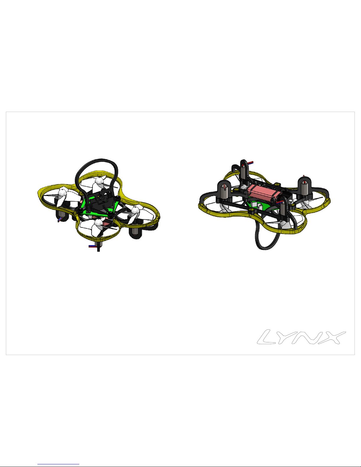
Fly Direction REF
Spider 65S-Main Frame PreAssembly with Shourd and
FC Mount
SPIDER 65S FPV RACER - USER MANUAL
2/6
REV. 01-DATE:02/16/2017
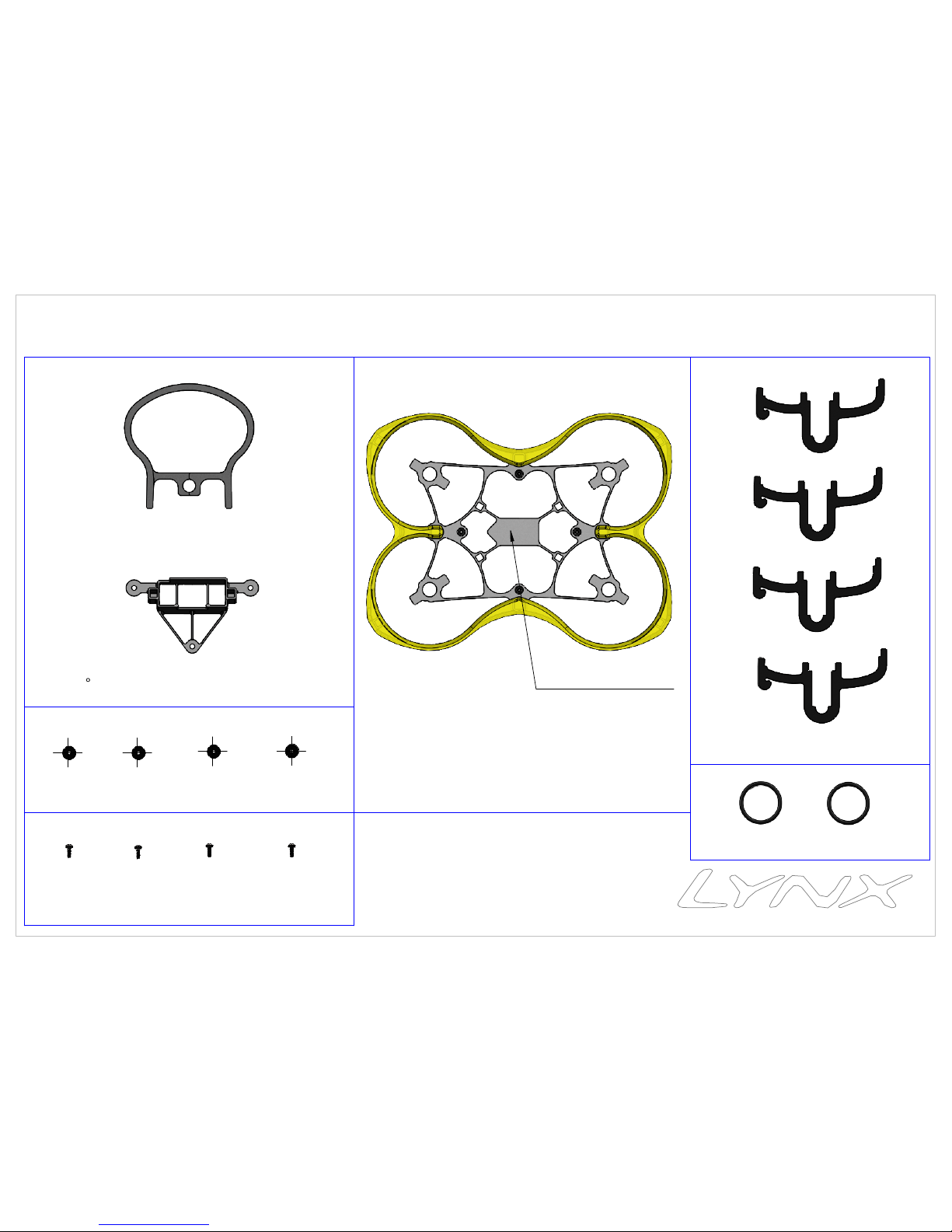
4 x Motor Mount
PACKAGE LIST PART
4 x M1x3 PANS Head Screw Silver
4 x Washer ∅4x∅1x0.5
15
FPV Camera Mount PTU-Black
2 x O-Ring ID 10 - W 1
HELI INNOVATIONS
Page 3

4 x Motor 6x15 mm
(18500/19000 KV suggest)
Motor Wire
Note: Rotate Motor in order Electric Wire will follow
the arrow, as showen
Fly Direction REF
Bottom View
Note 1: Pay attention Motor
Wire position to avoid short
circuit or pinching
SPIDER 65S FPV RACER - USER MANUAL
3/6
REV. 01-DATE:02/16/2017
Step 01: Motor Assembly
Step 02: Motor Mount Assembly
Note 2: Carefully press fit all 16 Motor Mount pins into
Frame sockets
HELI INNOVATIONS
Page 4

4 x M1x3 PANS Head Screw Self Tapping
Camera Mount
4 x Washer ∅4x∅1x0.5
Flight Control (Furious FPV Acrowhoop V2 suggest)
(Assembly FC following Fly direction REF)
FLY DIRECTION REF
FRONT
(Extra information for FPV Camera Mount PTU, see page
number 6)
SPIDER 65S FPV RACER - USER MANUAL
4/6
REV. 01-DATE:02/16/2017
Step 03: Flight Control Assembly
BACK
After assembly FC with Frame, connect Motor with FC.
Note: Assembly Motor Wire following below picture
Motor Wire
HELI INNOVATIONS
Page 5

BOTTOM VIEW
2 x Oring 10x12 x Oring 10x1
Battery
2 x CW propeller
2 x CCW propeller2 x CCW propeller
2 x CW propeller
Fly Direction
Step 05: Propeller Assembly
Step 04: O-Ring Battery Support Assembly
REV. 01-DATE:02/16/2017
5/6
SPIDER 65S FPV RACER - USER MANUAL
Note rotation direction of the Propeller
FRONT
BACK
BACK
FRONT
Fly Direction
HELI INNOVATIONS
Page 6

HELI INNOVATIONS
Roll bar
Note: Slot face lens
Camera Mount
Camera
Inductrix FPV Rollbar Camera Mount TPU - 7/15/20 deg Set - V2 - Manual
Roll Bar into Camera Mount socket (as showen)
Step 01: Insert Camera into Camera Mount
Step 02: Insert Roll Bar into Step 01, press fit
REV. 01-DATE:01/13/2017
Insert the Roll Bar Pins
into Camera Mount sockets
and press fit carefully
 Loading...