

Page 1
™
L
YNX
User's Guide
®
SIGNWarehouse
com
lynx_man_rev1_0504
Page 2

Table of Contents
1. – Learning
1.1 Initial Inspection 1-1
1.2 Front View of Lynx 1-2
1.3 Back View of Lynx 1-2
1.4 Side View of Lynx 1-4
2. – Installation
2.1 Installation 2-1
2.2 Stand and Media Handling System Installation 2-2
2.3 Blade Installation 2-6
3. – Connecting the Cutter
3.1 Parallel Transmission 3-1
3.2 Serial Transmission 3-1
3.3 Transmitting the data to the plotter 3-2
3.4 Interface for Macintosh Plus/SE/II 3-2
3.5 USB Port 3-3
4. – Basic Operation
4.1 Loading the sheet media 4-1
4.2 Loading the roll media 4-3
4.3 Control Panel 4-6
4.4 Power On 4-7
4.5 ON/OFF Line Key 4-8
4.6 Pause Key 4-8
4.7 Repeat Key 4-9
4.8 Data Clear Key 4-9
4.9 Origin Setting 4-9
4.10 Dip Switch Setting 4-10
4.11 Adjusting the Offset Value 4-10
4.12 Tracking Performance 4-12
4.13 Cutting Test 4-13
4.14 Adjusting the Tool Force 4-14
4.15 When Completing the Cutting Job 4-14
5. – Care & Basic Maintenance
5.1 Cleaning the Cutter 5-1
5.2 Cleaning the Grid Drum 5-2
5.3 Cleaning the Pinch Rollers 5-2
6. – Troubleshooting
6.1 If the Cutter is not Operating 6-1
6.2 Light Indicators 6-2
6.3 Warning Indicators 6-2
6.4 Error Indicators 6-4
6.5 Cutting Quality Problem 6-5
Appendix I – Specifi cations
Quick Menu I
Important Information II
About The Tool III
Optional Accessories IV
Equipment Specifi cation V
Page 3

1. Learning About Your Cutter
1.1 Initial Inspection
Before setting up your cutter/ plotter, please carefully unpack and inspect what you have received from
the shipped carton by comparing them with the following listed items. If you discover any item missing
in the process of delivery, please call Customer Service.
Item Quantity
Cutting Plotter Body
Accessory Bag
Roll Base
Serial Cable (RS-232C)
Cutter Tool
Cutting Pad
Tweezers
User’s Guide
AC Power Cord
Blade Holder
Blade (PLTB-ROLAND-45)
Water-Based Fiber-Tip Pen: 0.3 mm tip width
Parallel Cable
1
1
1
1
1
1
1
1
1
1
1
1
Stand & Flexible Media Support System includes:
(Please see 2-1 for Installation)
• Stand set and accessory box
• Roll Media Flange
• Roll Holder
• Roll Holder Guide bushes
• Roll Holder Support
1. Learning About Your Cutter 1-1
24” Lynx Optional Item Quantity
1
2
2
4
2
Page 4
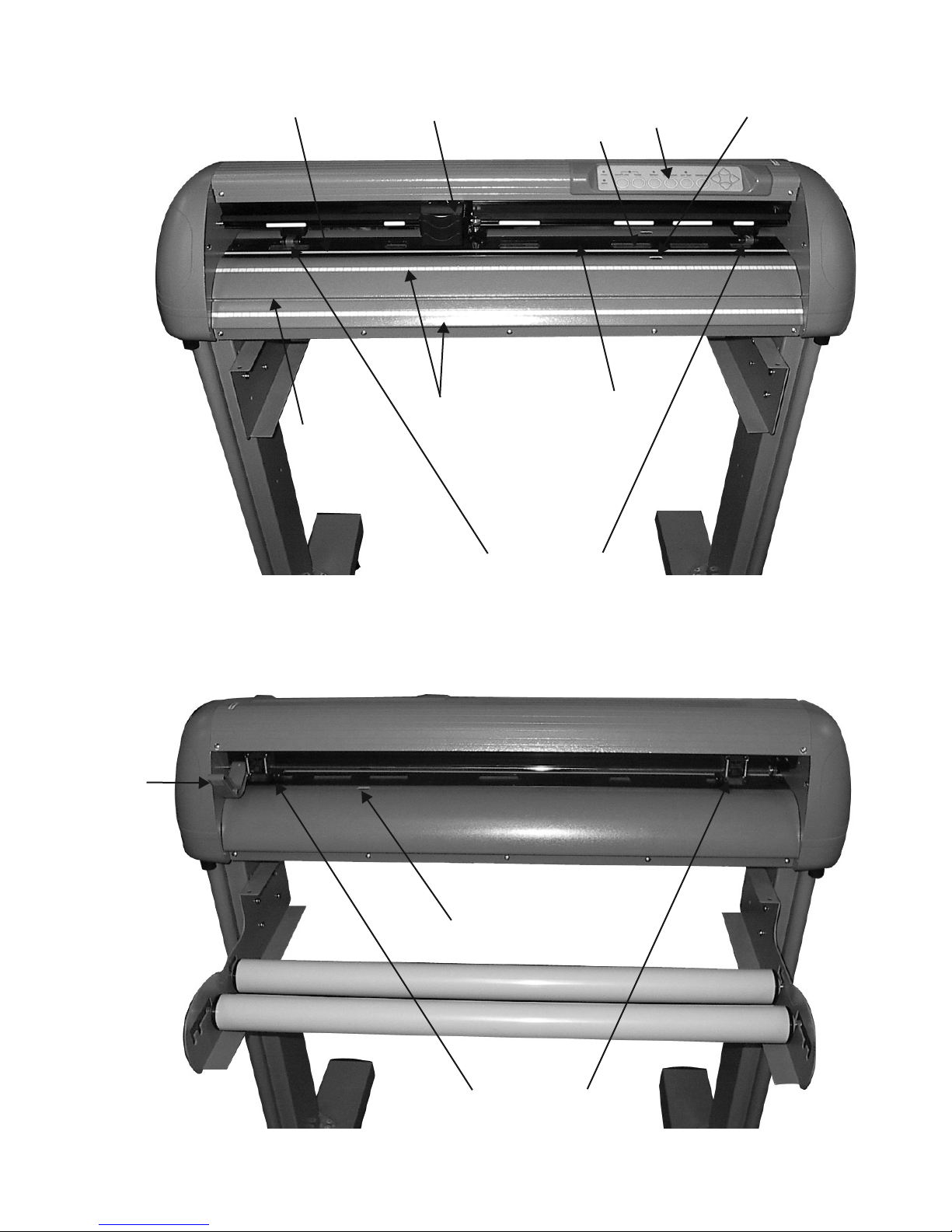
1.2 Front View of Lynx ( see Figure 1-1)
Figure 1-1
Cutting Pad
Knife Guide
Tool Carriage
Alignment Rulers
Grid Drum
Pinch Rollers
Control Panel
Platen
Paper Sensor
1.3 Back View of Lynx ( see Figure 1-2)
Lever
Figure 1-2
Paper Sensor
1. Learning About Your Cutter 1-2
Pinch Rollers
Page 5
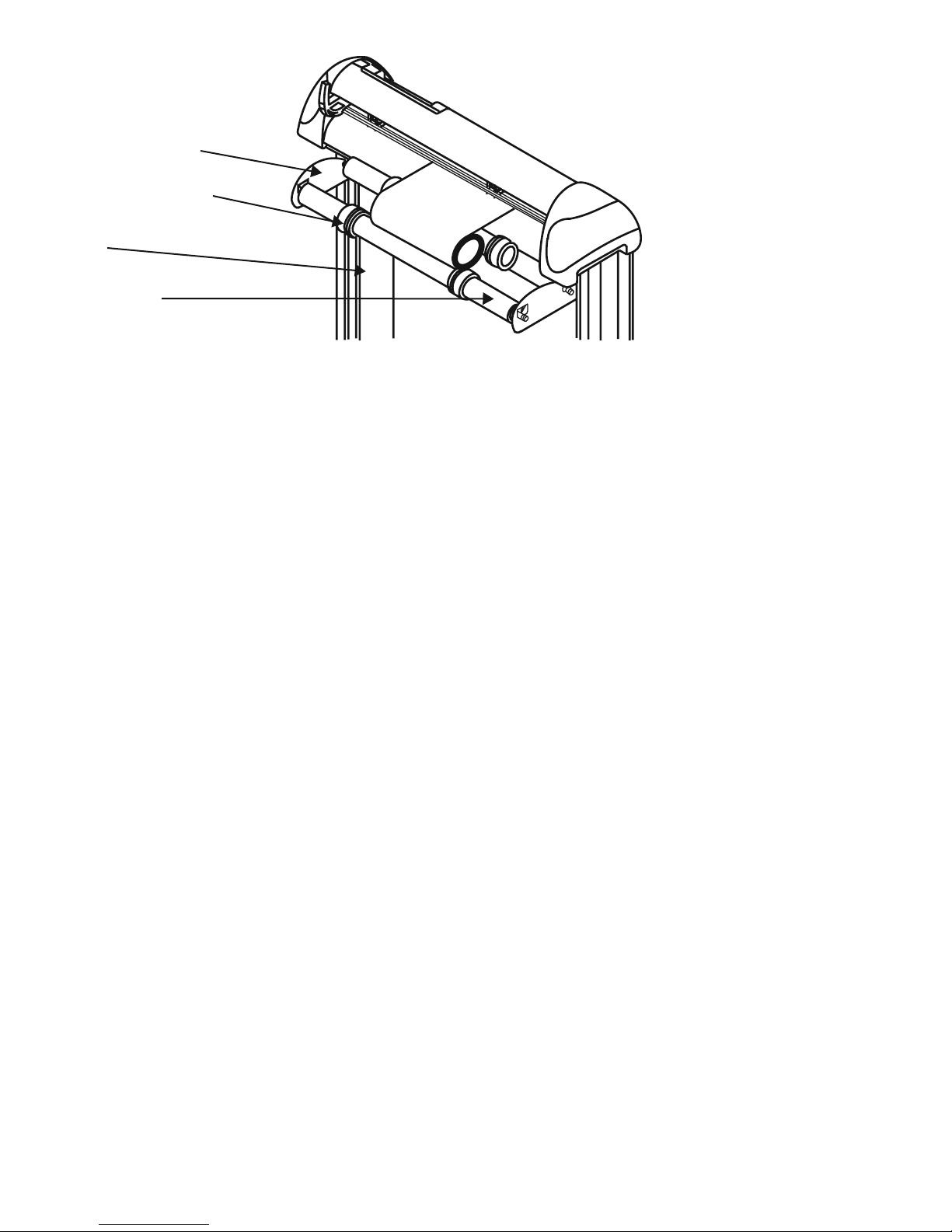
Roll Holder Support
Media Roll Flanges
Stand
Roll Holder
Figure 1-3
1. Platen - Provides the surface for holding and supporting media during cutting.
2. Cutting Pad - Provides protection for the blade while the blade is cutting.
3. Alignment Ruler – Media can be aligned with the clear guide line marks.
4. Tool Carriage – This unit performs the cutting with the installed blade and pen
5. Grid Drum - Moves the media back and forth during operation.
6. Control Panel - Consists of 10 control keys and 6 LEDs.
7. Pinch Roller – Presses the media against grid drum during cutting.
8. Knife Guide – Easily cuts off extra media with this groove.
9. Lever - Raises or lowers the pinch rollers.
Optional Items (see Figure 1-3)
1. Roll Holder – Consist of two rollers to hold and feed the roll media for cutting.
2. Roll Holder Guide Bushings - Serves to keep the roll media in place when media is pulled from the roll.
3. Media Roll Flanges - Secures media roll fl anges in place.
4. Roll Holder Support - Supports roll holders.
5. Stand - Supports the cutting plotter body.
1. Learning About Your Cutter 1-3
Page 6
This is a vinyl cutter. It is not intended to be used with windows drivers or as a printer.
Signwarehouse.com does not recommend that you use these drivers.
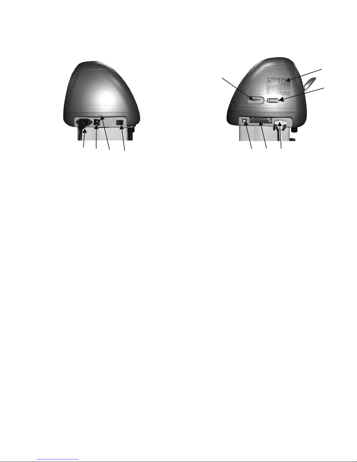
1.4 Side View of Lynx
Figure 1-4 Figure 1-5
5
7
6
1 2 3 4
Left Hand Side (Figure 1-4)
8 9 10
1. AC Power Connector – Used to insert the AC power cord.
2. Fuse – Up to 3 Amps.
3. Voltage Switch – The presetting is 230 voltage. Please adjust to comply with your local standard.
4. Power Switch – On when switches to [I]; Off when switches to [O]
Right Hand Side (Figure 1-5)
5. Dip Switch label – Indicates the functions of the dip switches.
6. Dip Switch - Used for various parameter settings.
7. Pen Force Control Slider – Set the blade force here.
8. Universal Serial Bus Connector- Used in conjunction with Windows Printer Drivers to connect
the cutting plotter to a computer through a Universal Serial Bus Cable.
9. Serial Interface Connector (RS-232C) – Used to connect the cutting plotter to a computer
through a serial interface cable.
10. Parallel Interface Connector (Centronics) –Used to connect the cutting plotter to a computer
through a parallel interface cable.
1. Learning About Your Cutter 1-4
Page 7

2. Installation
2.1 Installation
Caution 1
• Make sure the power switch is off before installing the cutting plotter.
• Carefully handle the cutter to prevent any injuries.
Caution 2 Choosing a proper place before setting up the cutting plotter
Before installing your cutting plotter, select a suitable location, which meets the following conditions.
• The machine can be approached easily from any direction.
• Keep enough space for the machine, accessories and supplies.
• Keep the working area stable, avoiding severe vibration.
• Keep the temperature between 41o-104oF in the workshop. (High temperature may damage vinyl).
• Keep the relative humidity between 30% and 70% in the workshop.
• Protects the machine from dust and strong air current.
• Do not place machine in direct sunlight.
Caution 3 Connecting the Power Supply
Check the plug of the power cord to see if it mates with the wall outlet. If not, please contact your dealer.
• Insert the plug (male) into a grounded power outlet.
• Insert the other end (female) of power cord into the AC connector of the cutting plotter.
2. Installation 2-1
Page 8
2.2 Stand & Flexible Media Handling System Installation
(The Stand and Flexible Media Support System for Lynx S-60 is optional)
Step 1
Examine supplied items in the accessory box of stand carton:
• 20 pieces of M6 (Alan head) screws
• 20 pieces of spring washers
• 20 pieces of washers
• 4 pieces black wheels (casters)
• 1 piece of M6 L- shape hexagon screw driver
• 1 piece of M6 wrench
Step 2
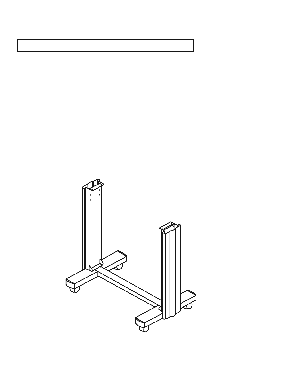
• The stand includes fi ve parts as Figure 2-1, follow the fi gure number to assemble.
Figure 2-1
2. Installation 2-2
Page 9
Step 3
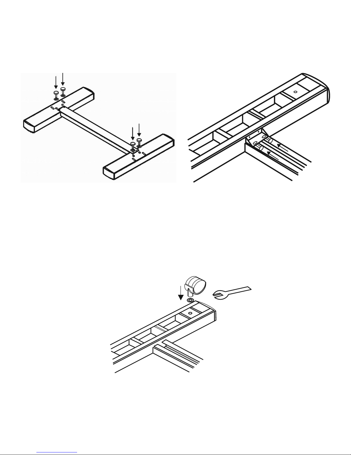
• Use M6 screws, washers and spring washers to assemble part 1 and 2, then use the screwdriver to
tighten them; this creates an H-shaped base. Figure 2-2 and 2-3 (reverse of the H-stand) will show you the
position to insert screws.
Figure 2-2
Figure 2-3
Step 4
• Insert the black wheels with washers into the holes on the bottom of H-shape stand as shown in Figure
2-4. Use the wrench to fasten them.
2. Installation 2-3
Figure 2-4
Page 10
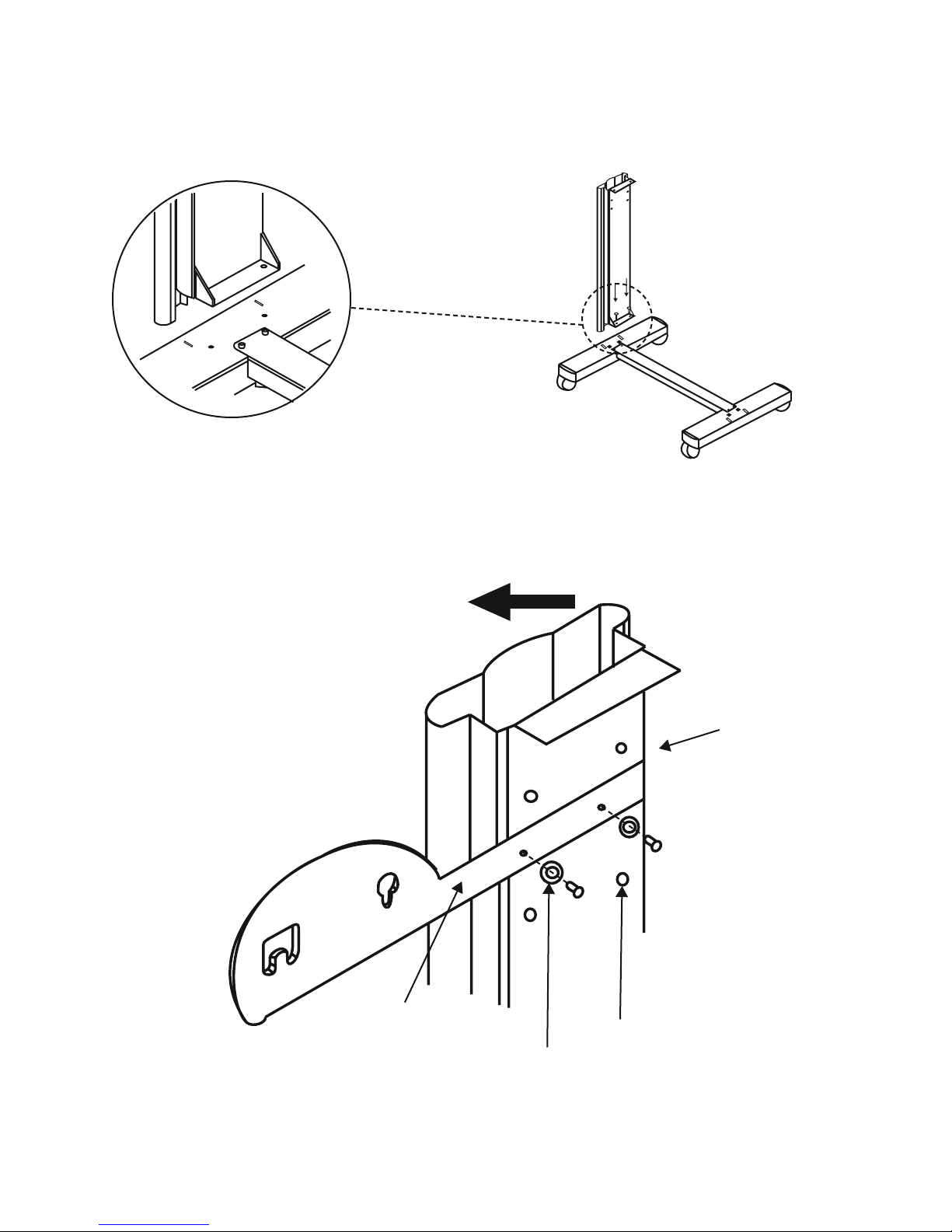
Step 5
• Then connect part 3 and H-shape stand. First, position the extension of part 3 into the squares holes on
H-stand. Second, insert the screws and washers into the holes besides the squares then tighten them (Figure 2-5).
Figure 2-5
Step 6
• Remove the cutting plotter from the carton. Position your stand under the plotter, then insert the screws
into the holes on plotter’s bottom. In order to make the task easier, you may need someone to help you.
Figure 2-6
Extension
2. Installation 2-4
3
Screws holes
Square holes
Page 11
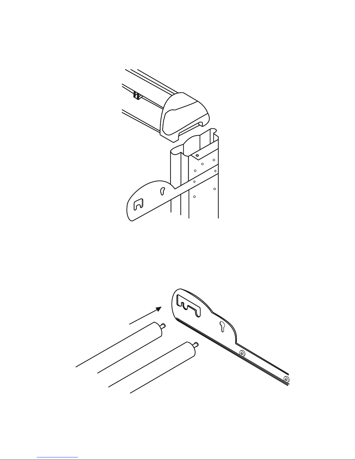
Step 7
• Insert the roll holder support with the screws into the holes of the stand then tighten them as Figure 2-6.
You can choose roll holder support’s position by inserting into different holes.
Figure 2-7
Step 8
• Place two roll holders into the holes in the roll holder support (Figure 2-8). The nuts at the end of the
roll holders will need to be unscrewed to install them.
Figure 2-8
2. Installation 2-5
Page 12
Step 9
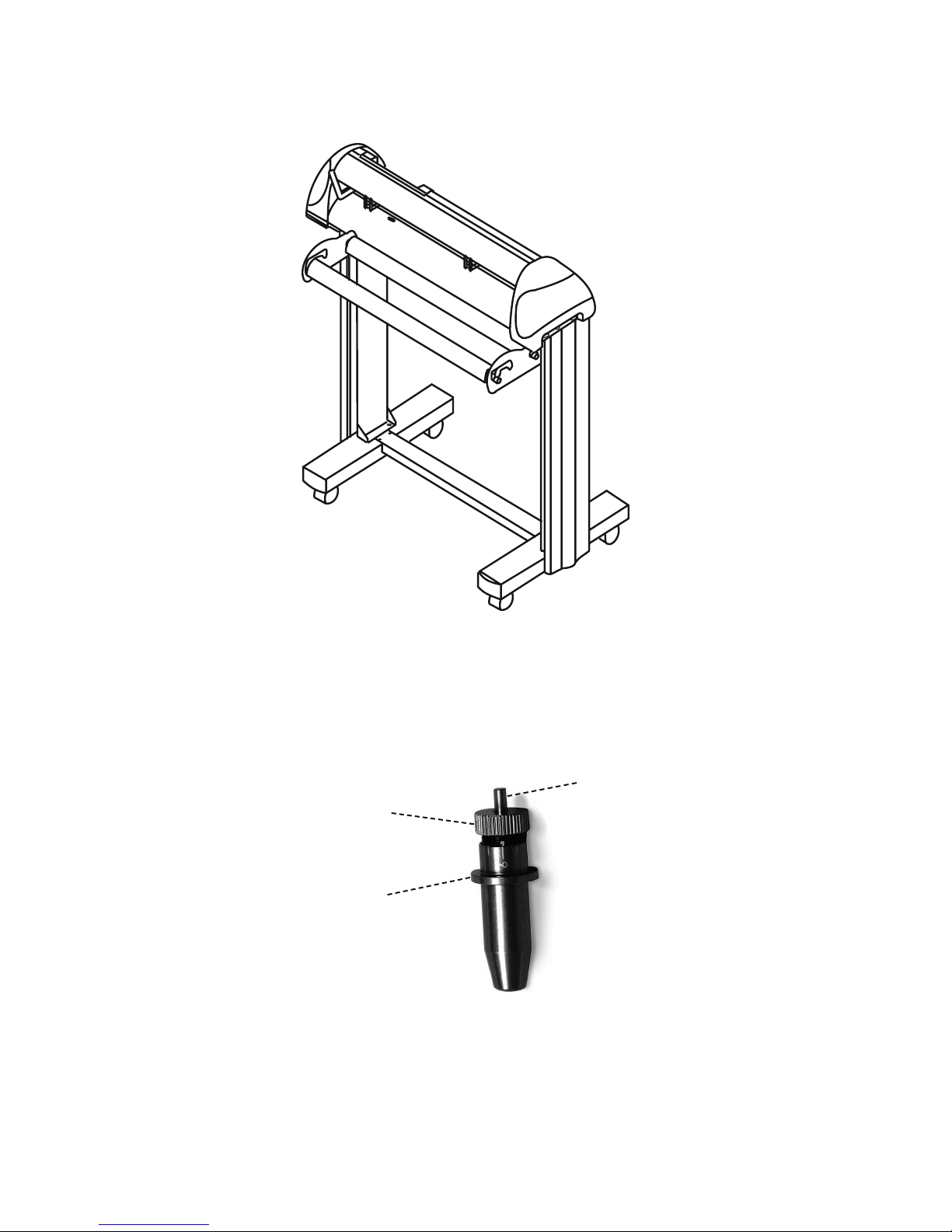
• The complete picture will be like Figure 2-9.
Figure 2-9
2.3 Blade Installation
Figure 2-10 is the illustrator of the blade holder. Insert a blade into the bottom of the blade holder and remove
the blade by pushing the pin. Make sure that your fi ngers are away from the blade tip.
Pin
Adjustment depth knob
Outward ring
2. Installation 2-6
Figure 2-10
Page 13
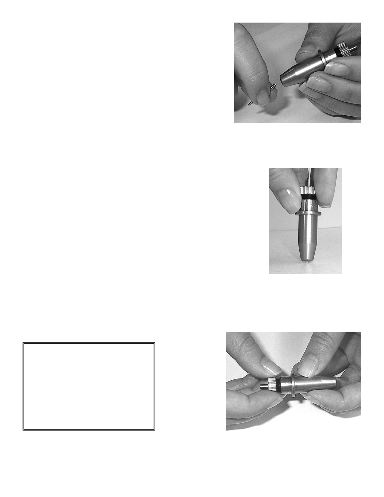
Step 1
Install blade (Figure 2-11).
Step 2
Push the blade to the bottom of the blade holder. (Figure 2-12).
Figure 2-11
Figure 2-12
Step 3
Adjust the blade tip to suitable length by screwing “Blade tip adjustment screw” clockwise or count-clockwise.
(Figure 2-13).
Tips:
“The proper length” means the blade’s
length is adjusted 0.1mm more than
fi lm’s thickness. That is, if the thickness
of fi lm is 0.5mm, then blade’s length
is properly adjusted 0.6mm and it can
completely cut through the fi lm layer
yet avoid penetrating the backing.
Figure 2-13
2. Installation 2-7
Page 14

Step 4
Insert the blade holder into tool carriage. Please note the outward ring of the holder must be placed into the
grooves of carriage fi rmly (see Figure 2-14), then fasten the case (Figure 2-15)
Figure 2-14 Figure 2-15
Step 5
Use the reversing steps to remove the blade holder.
Step 6
Eject the blade. Push “Blade eject pin” to eject blade when the blade needs to be replaced.
Caution
The blade will lose its sharpness after a period of usage, and the cutting quality might be affected. Increasing the
cutting force, might do the trick. However, once the blade is worn out and no longer provides a reliable cutting,
you should replace with a new blade. The blade is a consumable and must be replaced as often as necessary
to maintain the cutting quality. The quality of the blade affects cutting quality. So be sure to use a high quality
blade to ensure good cutting results.
2. Installation 2-8
Page 15

3. Connecting Cutting Plotters
The cutting plotter communicates with a computer through a USB (Universal Serial Bus), Parallel port
(Centronics) or a Serial port (RS-232C). This chapter shows you how to connect the cutting plotter to a host
computer and how to set up the computer/cutting plotter interconnection.
!!Notice: When USB connection is enabled, both parallel port and serial port will be disabled automatically.
Figure 3-1
Lever
Serial Interface Connector
USB Port
Parallel Interface Connector
3.1 Parallel Transmission
Connecting to the Parallel Port (Centronics)
1. Connect a parallel cable to the cutting plotter and the host computer (Figure 3-1)
2. Set up the output port LPT1 or LPT2 from your software package
3.2 Serial Transmission
Connecting to the Serial Port (RS-232C)
1. For IBM PC, PS/2 users or compatibles, connect the RS-232C cable to the serial connector of the
assigned serial port (COM1 or COM2) of your host computer.
2. Set up the communication parameters (Baud Rate and Data Bits/ Parity) to match the setting of software
package, refer to chapter 3 – “Misc” key description.
3. Connecting the Cutter 3-1
Page 16

3.3 Transmitting the Data to Plotter
There are two options to transmit the data from the computer to the cutting plotter:
Option 1 - Recommended
With proper interface settings, the data can be transmitted from your application software package to the
cutting plotters directly.
Option 2
Most cutting software packages are able to emulate HP-GL or HP-GL/2 commands, therefore, Use DOS
commands like TYPE or PRINT to output your fi le. As long as the fi le is HP-GL or HP-GL/2 format, the
cutting plotter can output the data precisely.
For example, a fi le with PLT extension generated by SignLAB can be transmitted directly to the plotter at the
DOS prompt, and then be cut out. Before outputting at the DOS prompt, set up a transmission protocol between
your cutting plotter and computer by a DOS command, MODE. Make sure that your PC has the same
communication protocol as the cutter. For example:
MODE COM2: 9600, N, 8, 1, P
Then, use TYPE command to output via COM2 if COM2 is the assigned output port.
TYPE fi lename > COM2
Tip:
Add the MODE command line to your system’s AUTOEXEC.BAT to automatically execute MODE
command every time you want to output your data at the DOS prompt via serial connection. However,
values in a MODE command should comply with the related requirements of your software. Refer to
DOS manual for further information.
3.4 Interfaces for Macintosh Plus/SE/II
Note: Modern Macs need a USB to PIA cable to communicate with the Lynx cutter.
You must have a USB to PIA cable to successfully connect your Macintosh to a Lynx cutter.
3. Connecting the Cutter 3-2
Page 17

3.5 USB Port
The USB port can only be used in conjunction with windows drivers. The windows drivers are available at
http://techsupport.signwarehouse.com/HTML/Cutters/index.html
***DISCLAIMER***
This is a vinyl cutter! It is not intended to be used with windows drivers or as a printer. SignWarehouse.com
does not recommend that you use these drivers.
Mac USB PIA Cable
Back of PC
Monitor Connection
PC Parallel Cable
Parallel Port
(LPT 1)
Back of laptop computer
3. Connecting the Cutter 3-3
PC Serial Cable
Serial Port
(COM 1)
Figure 3-3
Page 18

4. Basic Operation
4.1 Loading the Sheet Media
To load the media properly, please follow the procedures listed below:
1. Use the lever on the upper right side of the cutting plotter to raise or lower down pinch rollers. Pull the
lever forward until it makes a clicking sound then the pinch rollers are raised (Figure 4-1).
Lever
Figure 4-1
2. Load your media on the platen and slide it under the pinch rollers from the backside. The alignment
rulers on the platen extension will help you to adjust the media precisely.
Note:
The media must cover the paper sensors on the platen when loading
the media. At least one of the two paper sensors (Figure 4-2) should
be covered. Once the media covers the sensor, the cutting plotter
will size the media’s width and length automatically.
Front View Of Lynx
Figure 4-2
Paper Sensor
Back View Of Lynx
4. Basic Operation 4-1
Page 19

3. Move the pinch rollers manually to the proper position. The pinch rollers must be positioned above the
grid drum. The white marks on the main beam will remind you where the grid drums are (Figure 4-3). The
cutting head will not cut outside of the pinch rollers. The distance between the pinch rollers is your maximum
cutting distance.
White Marks
Figure 4-3
4. Push the lever backward to lower down the pinch rollers.
5. Turn on the power; the tool carriage will measure the size of the media automatically, and the plotting
cutter will begin to work.
Note:
• Move the pinch roller by applying force at the rear portion of the pinch roller support. Do not move it
by holding its front rubber roller (Figure 4-4)
Figure 4-4
(O)
4. Basic Operation 4-2
(X)
Page 20

4.2 Loading the Roll Media
First, put the roll media guide bushes on two roll holders (Figure 4-5) but do not lock them down.
Roll Media Guide Bushes
Figure 4-5
Option A (Recommended)
1) Insert the two roll holders into the roll media support set then place the roll media directly between the
two roll holders (Figure 4-6).
Figure 4-6
Option B (use the media fl anges)
1) Insert a roll media fl ange at the end of each roll media and tighten the thumbscrew until the roll media is
fi rmly gripped (Figure 4-7).
4. Basic Operation 4-3
Figure 4-7
Page 21

2) Then put the roll media on the roll holders. Adjust the position of the roll media to ensure that media
fl anges are able to run in the grooves of media guide bushes (Figure 4-8). Make sure the roll is directly behind
where the vinyl lines up on the front of the cutter. Then lock down roll media guide bushings.
Figure 4-8
3) Loading the media on the platen. Please refer to “2.4.1. Loading the sheet media.” After loading the roll
media, fl atten the media on the platen and hold the front edge of the roll media fi rmly (Figure 4-9).
4. Basic Operation 4-4
Figure 4-9
Page 22

4) Then turn the roll downward to make an equal tension across the media (Figure 4-10)
Move the pinch rollers to the correct
location and be careful that the pinch
rollers are positioned above the grid
drums.
Push the lever backward to lower down
the pinch rollers
Figure 4-10
5) Adjust and tighten roll media guide bushes on the roll holder to
secure the roll media
Make sure that the media tension
is equally distributed from left
6) Turn on the power switch, and then the tool carriage will size the
media automatically. Then the cutting plotter is ready to work.
to right. If the media is not tight
enough against the platen it will
cause tracking problems.
7) Use the reverse steps to remove the media.
You can also use the ROLL BASE to feed a roll media. Please adjust the position of roll base to get a good
cutting result (Figure 4-11).
Figure 4-11
4. Basic Operation 4-5
Page 23

4.3 Control Panel
Figure 4-12
1. ON/OFF LINE Key – Used for communication between the cutting plotter and the host computer.
When ON LINE condition, the LED above is on. Press the ON/OFF LINE LED again to turn off.
2. PAUSE Key – Pressing this key once can temporarily terminate the motion of the cutter, and the ON/
OFF LINE LED fl ashes. Press ON/OFF LINE Key can release the paused state and resume cutting.
3. REPEAT Key- Press this button to repeat the last cutting and the REPEAT LED turns on.
4. DATA CLEAR Key - Press this key to clear the data in the buffer memory. At this moment the DATA
CLEAR LED turns on.
5. CUT TEST Key - To test the set value before starting your cutting job. While doing the cut test, the
CUT TEST LED is on.
6. ORIGIN SET Key – This key sets a new origin point for cutting to the current tool position.
7. ARROW Key – Used to move the media or the cutting carriage.
8. POWER LED – Turn on the power, the POWER LED on.
9. ERROR LED – When this LED is on or fl ashing indicates various problems or errors. To fi nd the cause
of the problems, see Chapter 5 “Troubleshooting”.
Note: Steps 3 through 7 require the cutter to be OFFLINE.
4. Basic Operation 4-6
Page 24
4.4 Power On
• Be sure not to put hands or anything else on the platen of the
plotter when turning on the power. It may cause injury.
• Keep long hair away from the grid drum when power is on.
Turn on the power switch on the left-hand side of the cutting plotter. The POWER LED will come on; the cutting plotter is ready to receive data from computer. Below is control panel lights when the different function
keys are in normal conditions.
Function Power Error On/Off
Line
on-line state
pause state
off-line state
repeat
data clear
cut test
origin set
= fl ash = on = off
Repeat Data
Clear
Cut Test
4. Basic Operation 4-7
Page 25

4.5 ON/OFF LINE Key
• On - line
When the machine is in the “ON LINE” condition, the ON/OFF LINE LED on, the cutting plotter is ready to
receive data from the host computer. At this moment, only “PAU S E” and “ON/OFF LINE” keys are valid.
Change the setting value of dip switch
1. Press the PAUSE key to change the setting value during cutting.
2. Press the ON/OFF LINE key to continue cutting.
Terminate the cutting & clear the data in the buffer
Press the ON/OFF LINE key or press the PAUSE key
Then press the DATA CLEAR key
• Off - line
When the machine is “OFF Line”, the ON/OFF LINE LED is turned off. At this moment, you can change the
dip switch setting and do a cutting test and set the new origin as well. Pressing the key again will let the cutting
plotter switch to the “ON LINE” condition, and will resume the suspended operation. But there might be some
data loss during this interruption.
4.6 PAUSE Key
The purpose of the “PAUSE” key is to temporarily terminate the motion of the cutter after it started cutting. At
this moment, the ON/OFF LINE LED will fl ash; you can change the dip switch setting and the cutting force. It
will resume cutting after pressing the ON/OFF LINE key to make the machine in on-line status.
Note:
The parameters of dip switch in effect can not be changed while the cutting has
started unless pressing the “PAUSE” key. When press the “PAUSE” key, you
can change the setting.
4. Basic Operation 4-8
Page 26

4.7 Repeat Key
Lynx can repeat your last cutting job at the same position by pressing the REPEAT key without setting a new
origin. If you’re using a thicker media, it is better to use this function to avoid damaging your blade.
Procedures:
1. After cutting fi nishes, use the ARROW keys to move the tool carriage. Move to your desired position
for repeating the cutting job, and then press the ORIGIN SET key. The ORIGIN SET LED lights, and new
origin point is set.
2. Press the REPEAT key to start re-cutting job, and the REPEAT LED lights.
4.8 DATA CLEAR Key
The purpose of the DATA CLEAR key is to clear the data in the buffer memory. The DATA CLEAR key only
works when cutter is paused or offl ine. When use this function, the DATA CLEAR LED will light.
4.9 Origin Setting
Use the ORIGIN SET key to set a new origin at any position in the cutting area from where the tool carriage
starts to work. Please note that a new origin setting must be made under the off-line condition.
Procedures:
1. After loading the media and lowering down the level, use ARROW keys to move the carriage to the
desired location for a new origin.
2. Press ORIGIN SET key and the origin point is set. The ORIGIN SET LED lights.
4. Basic Operation 4-9
Page 27

4.10 Dip Switch Setting
To get a perfect cutting job, you have to choose the proper dip switch setting. The table below shows function of
each dip switch. See the default setting values Figure 4-13.
Dip Switch Function Switch Down Switch Up Default Value
SW 1-3 Offset Value (please refer to SW 1-3) 0.275 mm
SW-4 Media Weight Light Heavy Light Media
SW-5 Quality Draft Fine Draft
SW-6 Smooth Enable Disable Enable
SW-7 Auto Unroll Enable Disable Enable
SW-8 Media Type Roll Single Roll
ON
1 2 3 4 5 6 7 8
OFF
4.11 Adjust Offset Value
The square cut out should appear as one of the follow fi gure:
AA
Lower offset value
OR over-speed
BB
Higher offset
value
Figure 4-13
CC
offset value
If the square appears in BB or CC layout, Change the OFFSET by referring the dip switch part to adjust the
value to the optimum result. OFFSET is the distance that the blade tip is displaced from the center-line of the
blade.
4. Basic Operation 4-10
Page 28

SW 1-3: OFFSET SETTING
The fi rst three dip switches represent 8 different offset values as below:
0.000
0.175
0.250
0.275
0.300
0.500
0.750
1.000
SW-4: MEDIA WEIGHT (SPEED)
The fourth dip switch from the left sets the upper limit for cutting speed. Heavy media has a smaller upper limit.
The value of the cutting speed can be changed from the driver.
Heavy media is used so the upper limit for cutting speed is 300 mm, default is 30mm/s.
Light media is used so the upper limit for cutting speed is 600mm default is 330mm/s.
SW-5: QUALITY
There is a trade-off between Quality and Speed, the fi ner the cutting quality, the slower the cutting speed.
Fine quality
Draft quality
SW-6: SMOOTH
Make the curves smoother during cutting. When cutting small letters, it is recommend
to disable the smoothing cut.
Disable the smoothing cut.
Enable the smoorhing cut.
4. Basic Operation 4-11
Page 29
SW-7: AUTO UNROLL
Unroll heavy media at least 50 cm when the next point of movement is located beyond the unrolled position. If
the media type is single, this function is disabled.
Disable the auto unroll
Enable the auto unroll
SW-8: MEDIA TYPE
Set the type of the media you are using. When using a piece or single sheet of media, set it to “ON”; and set it to
“OFF” when using a roll media.
Single sheet of media is using.
A roll of media is using.
4.12 Tracking Performance
In order to achieve the best tracking performance for a long plot, we recommend some important media loading
procedures described as follows:
1. If the media length is less than 4 m, leave the margin of 0.5 mm~15 mm in the left and right edges of the
media (see Figure 2-14).
0.5mm - 15mm
0.5mm - 15mm
Pinch roller
4. Basic Operation 4-12
Figure 4-14
Pinch roller
Page 30

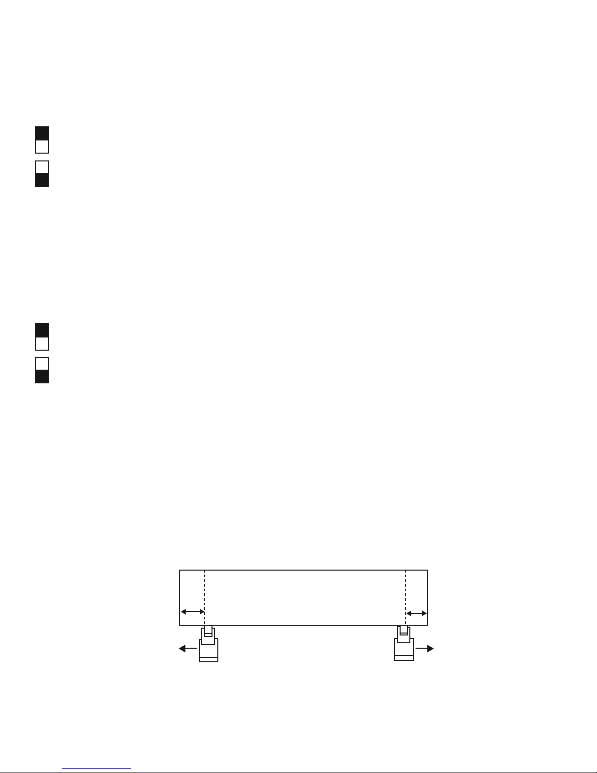
2. If the media length is greater than 4 m, leave at least 25 mm margin on the left and right edges of the media
(see Figure 4-15).
25 mm +
Pinch roller
Figure 4-15
Pinch roller
4.13 Cutting Test
In order to achieve the best cutting performance, it is necessary to set cutting conditions that match the cutting
media, giving considerations to the thickness of the sheet and type of material. Lynx can perform a cutting
test to determine the appropriate cutting force and offset value for your media and this can only work under
the off-line condition. Once you fi nish the cutting test, the new origin is also set to the current tool carriage
position.
Procedures:
1. After sizing the media, press the ON/OFF LINE key to change the plotter status to off-line condition.
2. Then use arrow keys to move the tool carriage to the position where you like your test to proceed.
3. Press the CUT TEST key to do the cutting test. The CUT TEST LED turns on.
Note:
The new origin is also set at the cutting test position.
4. Basic Operation 4-13
Page 31

4.14 Adjust Tool Force
When the cutting test is completed, a square cut out appears. Peel off the square to see if it can be easily
separated from the media base. If yes, the tool force is appropriate. If not, use “Pen Force Control Slider”
on the right-hand side of the plotter to adjust the tool force. First, move the control slider to the left-most
indicator mark (min. blade force), then increase the blade force gradually by moving the slider, until an
optimum force is obtained.
If you’re still unsatisfi ed with the cutting results after adjusting the blade force, then you should adjust the
offset value. After changing the offset value, perform the cutting test again and adjust the blade force.
4.15 When Completing the Cutting Job
After completing the cutting, raise the sheet loading lever, then remove the material. You can also cut off the
extra media with the cutter tool along the knife guide (Figure 4-16).
4. Basic Operation 4-14
Figure 4-16
Page 32

5. Care & Basic Maintenance
This chapter explains the basic maintenance (i.e. cleaning the cutting plotter) required for the cutting plotter.
Except for the below mentioned, all other maintenance must be performed by a qualifi ed service technician.
5.1 Cleaning the Cutting Plotter
In order to keep the cutting plotter under good condition and best performance, you need to clean the machine
properly and regularly.
Cleaning Precaution !
• Unplug the cutting plotter before cleaning in order to prevent electrical
shock.
• Never use solvents, abrasive cleaners or strong detergents for cleaning.
They may damage the surface of the cutting plotter and the moving parts.
Recommended Methods:
•
•
•
•
•
Gently wipe the cutting plotter surface with a lint-free cloth. If necessary, clean with a damp cloth or an
alcohol-immersed cloth. Wipe with water to rinse off any residue and dry with a soft, lint-free cloth.
Wipe all dust and dirt from the tool carriage rails.
Use a vacuum cleaner to empty any accumulated dirt and media residue beneath the pinch roller housing.
Clean the platen, paper sensors and pinch rollers with a damp cloth or an alcohol-immersed cloth, and dry
with a soft, lint-free cloth.
Wipe dust and dirt from the stand.
5. Care & Basic Maintenance 5-1
Page 33

5.2 Cleaning the Grid Drum
1. Turn off the cutting plotter, and move the tool carriage away from the area needed to be cleaned.
2. Raise the pinch rollers and move them away from the grid drum for cleaning.
3. Use a bristle brush (a toothbrush is acceptable) to remove dust from the drum surface. Rotate the drum
manually while cleaning. Refer to Figure 5-1
Figure 5-1
5.3 Cleaning the Pinch Rollers
1. If the pinch rollers need a thorough cleaning, use a lint-free cloth or cotton swab to wipe away the
accumulated dust from the rubber portion of the pinch rollers. To prevent the pinch rollers from rotating
while cleaning, use fi nger to hold the pinch rollers still.
2. To remove the embedded or persistent dust, use the lint-free cloth or cotton swab moistened
with rubbing alcohol.
5. Care & Basic Maintenance 5-2
Page 34

6. Trouble Shooting
This chapter helps you to correct some common problems you may come across. Prior to getting into the details
of this chapter, please be sure that your application environment is compatible with the cutting plotter.
Note:
Before having your cutting plotter serviced, please make certain
that the malfunction is in your cutting plotter, not the result of an
interface problem or a malfunction in your computer or a software
problem.
Why is the cutting plotter not functioning?
6.1 If the cutter does not operate?
If your Lynx doesn’t run, please check the following items fi rst:
Is the AC power cord plugged in properly?
Is the AC power cord connected to the power connector properly?
Is the power on?
Solutions:
If the POWER LED lights on, the cutting plotter should be in a normal condition. Switch off the cutting plotter
and turn it on again to see if the problem still exists.
If the POWER LED doesn’t light, contact the technician from your dealer.
6. Troubleshooting 6-1
Page 35

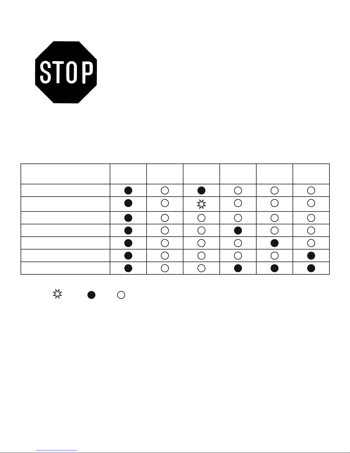
6.2 Light Indicators
Certain problems are identifi ed by the control panel lights. If your cutting plotter stops operating or the lights
are on or fl ashing unexpectedly, check the following descriptions of panel light patterns and the corrective
actions you should take.
6.3 Warning Indicators
When the ERROR LED fl ashes (as show below), take the necessary action according to respective instruction
below. If the problems are solved, the ERROR LED will turn off automatically. Press ON/OFF LINE key once
can also turn off the ERROR LED.
Warning Indicators Error On/Off
1 Graph was clipped
2 HPGL/2 command error
3 Lever up or no media
4 Cannot repeat
5 Communication error
6 Width sensor error
= fl ash = on = off
Warning 1 The graph is clipped
Line
Repeat Data
Clear
Cut Test
This condition indicates that the cutting graph exceeds the cutting limit. You can solve the problem by 1. Reload
the larger media 2. Move the pinch roller to have larger cutting width 3. Re-scale the plot to a smaller size. Then
send the cutting job again from your computer.
Warning 2 HPGL/2 command error
If your cutting plotter can not recognize the commands from your computer, please check that the commands
applied to your cutting plotter are used properly. Be sure it is the HP-GL/2 or HPGL command. Then send the
same cutting job to the plotter again, if it shows the same result, please contact your dealer.
6. Troubleshooting 6-2
Page 36

Warning 3 Lever up or no media
Check the lever position and be sure to put the media in the cutting plotter before cutting.
Warning 4 Cannot repeat cutting
This condition happens for two reasons: the buffer holds no data or the buffer is full. For the former condition,
please send a new graph from the computer; for the latter condition, please repeat the same cutting job from the
computer. In both conditions, press ON/OFF LINE key to clear the message.
Warning 5 Communication error
Check if the connection cable is connected to the cutting plotter and computer properly. If yes, then check if the
interface setting is correct, make sure your PC has the same communication protocol as the cutter – 9600 bps, no
parity, 8 bits, 1 stop bit, and none for hand shaking. If you have done the above, try the communication between
your cutting plotter and computer again. Press ON/OFF Line key to force the cutter to on line condition.
Warning 6 Width sensor error
Check if the pinch rollers are positioned above the grid drum and reload the media again.
6. Troubleshooting 6-3
Page 37

6.4 Error Indicators
If mechanical problems or failure during operations happen, the ERROR LED will turn on. Please follow the
instruction below to solve the problem. If the plotter still cannot work, please inform your dealer of these types
of error indicators or have your plotter serviced.
Error Indicators Error On/Off
Line
1 Sram error
2 Dram error
3 Check media, drum, or X motor
4 Check media or Y motor
= fl ash = on = off
Repeat Data
Clear
Cut Test
Error 1 and 2.
At this moment, please contact your dealer.
Error 3. Check media drum, or X motor
This message indicates that there might be a problem on the X axis. Check if the drum is working well and if
the media is well loaded. Correct the problem and re-power on to reboot system.
Error 4. Check media, or Y motor
This message indicates that there might be an obstruction to carriage relating to a problem on the Y axis. Correct
the problem and re-power on to reboot system.
6. Troubleshooting 6-4
Page 38

6.5 Cutting Quality Problems
Is the blade installed correctly and the blade
holder fastened securely?
Ye s
Replace with a
new blade.
Ye s
Is the blade dull or
chipped?
Ye s
Is the tool offset set
up properly?
No
Refer to the “Blade
Installation”.
No
Is tool force set up properly?
No
Adjust the tool force
to obtain an optimum
blade force. Refer to 2.13
“CUTTING TEST”
Ye s
Is there any
dirt adhered to
the blade?
Ye s
Remove the blade
and blade holder
and clean them.
No
Please contact your
dealer for technician
support.
6. Troubleshooting 6-5
No
Adjust the blade offset
to obtain an optimum
value.
Page 39

Quick Menu
1. Power ON (the POWER LED lights on)
2. Place the media and pull the lever to lower down the pinch rollers (make sure the pinch rollers are
positioned above the grid drums, that is, within the white marks).
3. The cutting plotter will size the media automatically according to the setting of the dip switch on
the right side of the cutter (usually the presetting is ROLL media type).
4. Off-line condition- Plotter is not ready to receive data from computer. Press ON/OFF LINE key, the
LED above is off.
5. On-line condition- Plotter is ready to receive data from computer. Press ON/OFF LINE , the LED
above lights.
6. Change the setting value during cutting - Press PAUSE key, the LED above fl ashes. To continue
cutting press ON/OFF LINE .
7. Terminate the cutting and clear the data in the buffer. - Press ON/OFF LINE or PAUSE and then
press DATA CLEAR .
A. Quick Menu I
Page 40

Important Information
Thanks for purchasing a Lynx cutting plotter. To optimize the performance of your Lynx, please take the time
to read through the user manual completely and follow up the correct operation procedure. Hope you will enjoy
using your cutting plotter.
SAFETY PRECAUTIONS!
Caution
• For safety concern, please always hold the cutter fi rmly from the bottom when moving it. Do not move the
cutter by clasping the depression area on both sides.
O (Correct)
Hold from the bottom
• Do not shake or drop the blade holder, blade tip can fl y out.
• During operation, do not touch any of the moving parts of this machine (such as the carriage). Also be
careful that clothing and hair do not become caught.
• Always connect the power cable to a grounded outlet.
• Always use the accessory power cable that is provided. Do not wire the power cable so that it becomes
bent or caught between objects.
• Do not connect the power cable to branching outlet to which other machines are also connected, or use
an extension cable. There is danger of overheating and of mis-operation of the machine.
• Keep the tools out of the reach of children.
• Always position the pinch rollers beneath the white marks.
X (Incorrect)
Hold the depression area
A. Important Information II
Page 41

About the Tool
OFFSET is the distance that the blade tip is displaced from the center-line of the blade.
Blade
Central line
Blade tip
Protrusion Length of the Blade
Protrusion length
of the blade
Thickness of the
base paper (t2)
Offset
Thickness of the
fi lm (t1)
Length of protrusion = t1 + t 2/ 2, but for your convenience you may just make it about 0.3~ 0.5 mm beyond the
blade holder tip.
A. About the Tool III
Page 42

Lynx Series Optional Accessories
The following items are available for Lynx series:
Item Part No. Description US Price
Vinyl Express Blade
(Fits all Vinyl
Express cutters)
Item Part No. Description US Price
Blade Holder P-BK02019A 1 oz US $75.00
PLTB-ROLAND-30 30° US $14.00
PLTB-ROLAND-45 45° US $11.00
PLTB-ROLAND-60 60° US $11.00
Item Part No. Description US Price
GRC-61/60/Lynx Cutting Pad 24” PLTA-ZZ700B-61 1 oz US $12.00
GRC-Lynx Cutting Pad 12” PLTA-ZZ800B-S30 1 oz US $10.00
A. Optional Accessories IV
Page 43

Equipment Specifi cation
Specifi cation: Lynx S-60, S-30
Model Name/ No. LYNX S-60
24” cutter
Operational Method Roller-Type
Max. Cutting Width 590mm (23.23in) 280mm (11.02in)
Max. Media Loading Width 719mm (28.3in) 459mm (18.07in)
Min. Media Loading Width 50 mm
Acceptable Material Thickness 0.8mm (0.03 in)
Number of Pinch Rollers 2
Drive DC Servo Control
Cutting Force 0~300 g
Max. Cutting Speed Up to 600 mm/sec (23.62 ips)
Offset 0~1.0 mm
Mechanical Resolution 0.009 mm
Software Resolution 0.025 mm
Distance Accuracy 0.254 mm or 0.1 % of move, whichever is greater
Repeatability + 0.1 mm up to 3 meters (*certifi ed media)
Buffer Size 4 MB
LYNX S-30
12”cutter
Interfaces Parallel (Centronics) & Serial (RS-232C)
Commands HP-GL, HP-GL/2
Confi gurable Origin Yes
Vector Look Ahead Yes
Curve & Arc Smoothing Yes
Test Cut Possibility Yes
Repeat Function Yes
Control Panel 10 Control Keys, 6 LED
Dimension (HxWxD) mm
(HxWxD) in
Net Weight (kg) 13 kg/ 28.6 lb 10.2 kg/ 22.4 lb
Power Supply 115V/230V (manual switch)
Environment Temperature 0
Environment Humidity 30% ~ 70% relative humidity (operating)
*This specifi cation is subject to change without prior notice.
220 x 879 x 258
8.67 x 34.61 x 10.16 lb
o
C~55oC / 32oF~131oF (operating)
-40oC~75oF~167oF (storage)
220 x 619 x 258
8.67x 24.37 x 10.16 in
A. Equipment Specifi cation V
 Loading...