

Page 1

LYNXTechnik AG
®
Broadcast Television Equipment
Reference Manual
R FR 5041
Series 5000 1RU 19” Rack Frame with Power Supply
(Suitable for up to four Series 5000 Modules)
Revision 1.3 – February 2012
Information in this document is subject to change without notice. No part of this document may be reproduced or
transmitted in any form or by any means, electronic or mechanical for any purpose, without express written permission of
LYNX Technik AG may have patents, patent applications, trademarks, copyrights or other intellectual property rights
covering the subject matter in this document. Except as expressly written by LYNX Technik AG, the furnishing of this
document does not give you any license to patents, trademarks, copyrights or other intellectual property of LYNX Technik
LYNX Technik AG.
AG or any of its affiliates.
LYNX Technik AG
Brunnenweg 3
D 64331 Weiterstadt
Germany
www.lynx-technik.com
© 2012 LYNX Technik AG all rights reserved
Page 2

Contents
R FR 5041 Reference Manual. Rev 1.3
Contents
Warranty ............................................................................................................... 4
Regulatory information ........................................................................................ 5
Europe ........................................................................................................................................ 5
USA ............................................................................................................................................. 5
WARNING.............................................................................................................. 6
WARNUNG! ........................................................................................................... 6
ESD Warning .............................................................................................................................. 7
Getting Started ..................................................................................................... 8
Packaging .................................................................................................................................. 8
Product Description .................................................................................................................. 8
Installation Instructions ...................................................................................... 9
Installations-Anweisung....................................................................................... 9
Power Supply ...................................................................................................... 10
Power Supply Alarm LED ....................................................................................................... 10
............................................................................................................... 2
Declaration of Conformity ....................................................................................................... 5
FCC 47 Part 15 ....................................................................................................................... 5
Rack Controller .................................................................................................. 11
Controller LED Indication ....................................................................................................... 11
Module Installation ............................................................................................ 12
Rack Connections .............................................................................................. 13
Rear Termination Panel .......................................................................................................... 13
AC Input and Fuses .............................................................................................................. 13
Rack Reference (Sync Connector) ....................................................................................... 14
Redundant Power Input ........................................................................................................ 14
Alarm Connection (Terminal Strip) ....................................................................................... 14
Alarm Function ...................................................................................................................... 14
LAN Connection (Remote Control) ....................................................................................... 15
Hot Swapping ..................................................................................................... 15
Power Supplies ........................................................................................................................ 15
Power Supply Failure ............................................................................................................ 15
CardModules ............................................................................................................................ 15
System Cooling and Fans ................................................................................... 16
Fan Replacement ..................................................................................................................... 16
Network Configuration ....................................................................................... 17
The Network Connection Manager ........................................................................................ 17
Page 2 of 34
Page 3

R FR 5041 Reference Manual. Rev 1.3
Configure IP Address.............................................................................................................. 19
Network Attaching the RFR 5041 ........................................................................................... 20
LYNX Desktop Controller Software ................................................................... 21
System Requirements............................................................................................................. 21
Software Installation ............................................................................................................... 21
Starting the Controller Application ....................................................................................... 23
Software Updates ................................................................................................................. 23
Software Operation ............................................................................................ 24
Control System Layout ....................................................................................... 24
Device List ............................................................................................................................... 25
User Defined Device List ...................................................................................................... 25
Module Properties ................................................................................................................... 27
New Control Window ............................................................................................................ 27
Module Title Area .................................................................................................................... 28
Locate Function .................................................................................................................... 28
Control Tabs ............................................................................................................................ 28
Power Supply Tab ................................................................................................................. 28
Settings Tab .......................................................................................................................... 29
HotSync Backup ...................................................................................................................... 29
Switching on HotSync ........................................................................................................... 30
Options Tab .......................................................................................................................... 31
Events Tab ............................................................................................................................ 32
Error Logging Area ................................................................................................................. 32
Service ............................................................................................................... 34
Technical Support ................................................................................................................... 34
Contact Information ........................................................................................... 34
Page 3 of 34
Page 4

R FR 5041 Reference Manual. Rev 1.3
Warranty
LYNX Technik AG warrants that the product will be free from defects in materials
and workmanship for a period of three (3) years from the date of shipment. If this
product proves defective during the warranty period, LYNX Technik AG at its
option will either repair the defective product without charge for parts and labor,
or will provide a replacement in exchange for the defective product.
In order to obtain service under this warranty, customer must notify LYNX
Technik of the defect before expiration of the warranty period and make suitable
arrangements for the performance of service. Customer shall be responsible for
packaging and shipping the defective product to the service center designated by
LYNX Technik, with shipping charges prepaid. LYNX Technik shall pay for the
return of the product to the customer if the shipment is within the country which
the LYNX Technik service center is located. Customer shall be responsible for
payment of all shipping charges, duties, taxes and any other charges for
products returned to any other locations.
This warranty shall not apply to any defect, failure, or damage caused by
improper use or improper or inadequate maintenance and care. LYNX Technik
shall not be obligated to furnish service under this warranty a) to repair damage
resulting from attempts by personnel other than LYNX Technik representatives to
install, repair or service the product; b) to repair damage resulting from improper
use or connection to incompatible equipment; c) to repair any damage or
malfunction caused by the use of non LYNX Technik supplies; or d) to service a
product which has been modified or integrated with other products when the
effect of such modification or integration increases the time or difficulty servicing
the product.
THIS WARRANTY IS GIVEN BY LYNX TECHNIK WITH RESPECT TO THIS
PRODUCT IN LIEU OF ANY OTHER WARRANTIES, EXPRESS OR IMPLIED.
LYNX TECHNIK AND ITS VENDORS DISCLAIM ANY IMPLIED WARRANTIES
OF MERCHANTABILITY OR FITNESS FOR A PARTICULAR PURPOSE. LYNX
TECHNIK`S RESPONISIBILITY TO REPAIR AND REPLACE DEFECTIVE
PRODUCTS IS THE SOLE AND EXCLUSIVE REMEDY PROVIDED TO THE
CUSTOMER FOR BREACH OF THIS WARRANTY. LYNX TECHNIK AND ITS
VENDORS WILL NOT BE LIABLE FOR ANY INDIRECT, SPECIAL,
INCIDENTIAL, OR CONSEQUENTIAL DAMAGES IRRESPECTIVE OF
WHETHER LYNX TECHNIK OR THE VENDOR HAS ADVANCE NOTICE OF
THE POSSIBILITY OF SUCH DAMAGES.
Page 4 of 34
Page 5

We LYNX Technik AG
Brunnenweg 3
D-64331 Weiterstadt
Germany
Declare under our sole responsibility that the product
TYPE: R FR 5041
To which this declaration relates is in conformity with the following
standards (environments E1-E3):
EN 55103-1 /1996
EN 55103-2 /1996
EN 60950-1 /2006
Following the provisions of 89/336/EEC and 73/23/EEC directives.
Winfried Deckelmann
Weiterstadt, February 2012
Place and date of issue Legal Signature
Regulatory information
R FR 5041 Reference Manual. Rev 1.3
Europe
Declaration of Conformity
USA
FCC 47 Part 15
This device complies with part 15 of the FCC Rules. Operation is subject to the following
two conditions: (1) This device may not cause harmful interference, and (2) this device
must accept any interference received, including interference that may cause undesired
operation.
Note: This equipment has been tested and found to comply with the limits for a Class A
digital device, pursuant to the part 15 of the FCC Rules. These limits are designed to
provide reasonable protection against harmful interference when the equipment is
operated in a commercial environment. This equipment generates, uses, and can radiate
radio frequency energy and, if not installed and used in accordance with the instruction
manual, may cause harmful interference to radio communications. Operation of this
equipment in a residential area is likely to cause harmful interference in which case the
user will be required to correct the interference at his own expense.
Page 5 of 34
Page 6

R FR 5041 Reference Manual. Rev 1.3
WARNING
Electrical supplies in excess of 50 (fifty) volts peak value are potentially hazardous or lethal. AC
supplies between 100 and 250 peak volts exist within the rack frame chassis when connected to
AC power. Only qualified personnel should service the rack frame assembly.
Removal of technical earth may render the equipment dangerous and intentional removal is
prohibited.
This unit has to be separated from mains by disconnecting the power supply cords.
This unit may have two power supplies and two power supply cords. Disconnect all power supply
cords before servicing to avoid electric shock.
DOUBLE POLE / NEUTRAL FUSING
After operation of the fuse, parts of equipment that remain energized might represent a hazard
during servicing.
For continued protection against risk of fire, replace only with same type and rating of fuse.
F1/F2: T2AH250V
Replacement AC fuses must be of the specified type and rating: F1/F2 = T2AH250V
The use of repaired fuses or shorting links has to be avoided.
WARNUNG! WARNING! CAUTION!
WARNUNG!
Wenn das Gerät an das Wechselstromnetz angeschlossen ist, treten innerhalb des Gerätes
Wechselspannungen zwischen 100 und 250 V auf, die potentiell gefährlich oder tödlich sein
können. Deshalb darf eine Reparatur und Instandhaltung nur von qualifiziertem Personal
durchgeführt werden.
Das Entfernen des Schutzleiters kann das Gerät in einen gefährlichen Zustand bringen,
vorsätzliches Entfernen des Schutzleiters ist verboten.
Das Gerät ist durch Abziehen beider Netzstecker vom Netz zu trennen.
Das Gerät kann 2 Netzgeräte mit 2 Netzkabeln haben. Vor Servicearbeiten müssen alle
Netzkabel abgezogen werden, um elektrischen Schlag zu vermeiden.
Die Netzzuführung ist 2-polig abgesichert. Nach Ausfall einer Sicherung können Teile der
Schaltung weiter unter Spannung bleiben und bei Servicearbeiten zu Gefahren führen.
Vor Servicearbeiten Stromversorgung unterbrechen und Teile vor Berührung prüfen.
Um Schutz gegen Feuer aufrechtzuerhalten, sind bei Sicherungswechsel nur Sicherungen des
gleichen Typs mit gleichen Daten zulässig. F1/F2 = T2AH250V
Page 6 of 34
Page 7
R FR 5041 Reference Manual. Rev 1.3
ESD Warning
The internal electronics parts of this product are static sensitive. Please use caution and
use preventative measures to prevent static discharge or damage could result to
modules.
Electrostatic discharge (ESD) damage occurs when electronic assemblies or the
components are improperly handled and can result in complete or intermittent failure.
Do not handle the module unless using an ESD-preventative wrist strap and ensure that
it makes good skin contact. Connect the strap to any solid grounding source such as any
exposed metal on the rack chassis or any other unpainted metal surface.
Caution
Periodically check the resistance value of the antistatic strap. The measurement should
be between 1 and 10 Megohms.
Page 7 of 34
Page 8
Getting Started
Packaging
The shipping carton and packaging materials provide protection for the rack frame during
transit. Please retain the shipping cartons in case subsequent shipping of the product
becomes necessary.
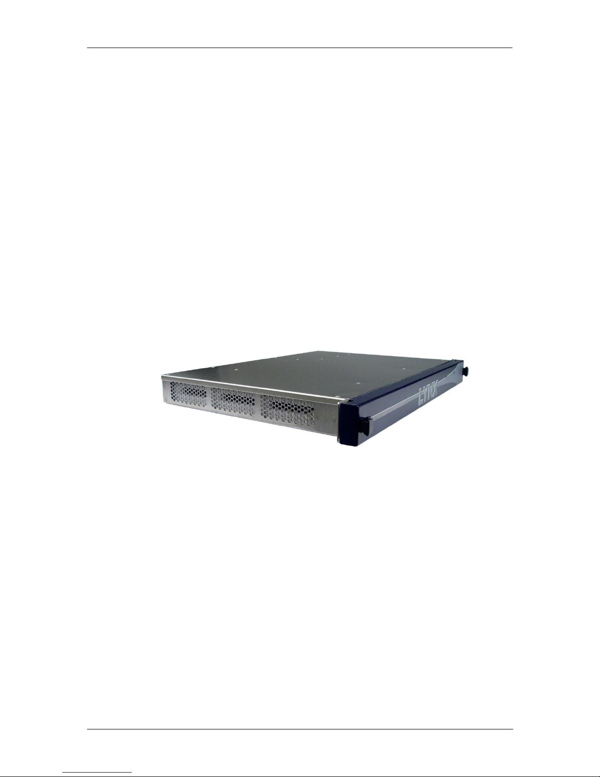
Product Description
The R FR 5041 is a high quality compact 1 RU high 19 inch rack frame enclosure for
LYNX Series 5000 CardModules, designed primarily for broadcast and professional
applications.
The rack frame can accept a maximum of 4 Series 5000 CardModules (any
combination*). Primary power supply and a fully integrated LAN port are also included
(LAN port is for remote control using the included LYNX Desktop Controller Software)
All CardModules and the Primary Power supply are installed and removed from the front.
Module rear connection panels are supplied with each CardModule and are mounted on
the rear of the rack as required. All CardModules and the power supply are hot
swappable.
R FR 5041 Reference Manual. Rev 1.3
*Note. Some Card Modules require a larger double height backplane (for I/O reasons)
which will occupy two pack slots. Please refer to individual module specifications for
details. These are typically the modules which currently have a double width backplane
when used with the RFR 5012 2RU rack frame.
The R FR 5041 features an integrated termination panel with connections for AC power
input, remote alarming, LAN control and a rack reference (sync). An external + 12VDC
power input connection is provided for optional external redundant power backup using a
brick power supply (Option R PS 5000)
The Rack frame has a hinged front cover providing easy access to all installed modules
and power supply which are hot swappable.
All electrical contacts inside the RFR 5041, CardModules and power supplies are gold
plated ensuring maximum reliability and protection from corrosion. Modules are
mechanically secured in place and will not shake loose with vibration (ideal for mobile
applications).
The R FR 5041 is one of the primary building blocks in the LYNX Series 5000
CardModule product line providing high quality, modularity and flexibility in a very small
form factor.
Page 8 of 34
Page 9

R FR 5041 Reference Manual. Rev 1.3
!
!
!
!
!
!
Installation Instructions
The RFR 5041 is intended for operation in broadcast environments. The operation of the
equipment in environments which could produce excessive dust, moisture or extreme
temperatures requires special accommodation, such as:
Dust filters
Air conditioning
Avoidance of condensation
CAUTION!
The power cords must meet the safety requirements of the country where the rack
frame is used and has to be approved in this country, e.g.
CE-Mark in Europe
UL-listed in USA
CAUTION!
The power supply cords are used to disconnect the R FR 5041 from the AC mains
supply, ensure that the AC socket-outlets are located/installed near the equipment and
are easily accessible.
CAUTION!
The rack frame chassis is CLASS I EQUIPMENT. Before initial operation ensure that
protective earth is connected to the facility wiring and zero potential is established.
The functional earth connection at the rear termination panel is connected internally to
protective earth. If necessary, it may be used for potential equalization to other units.
CSA certified in Canada
Installations-Anweisung
Das Gerät R FR 5041 ist für Anwendungen in Fernsehstudios vorgesehen. Der Einsatz in
erhöhter staubiger und feuchter Umgebung oder außergewöhnlichen Temperaturen erfordert
besondere Maßnahmen wie
Klimatisierung
Staubfilter
Vermeiden von Kondenswasser.
ACHTUNG!
Die Netzkabel müssen den Sicherheits-Anforderungen in dem Land entsprechen in dem
das Gerät verwendet werden soll und in dem Land zugelassen sein, z.B.
CE-Zeichen in Europa
UL-gelistet in USA
CSA-Zulassung in Kanada
ACHTUNG!
Die Netzkabel dienen zur Trennung des Geräts vom Netz. Es ist sicherzustellen, dass
die Steckdosen für den Netzanschluss in der Nähe des Gerätes angebracht und zum
Trennen leicht zugänglich sind.
ACHTUNG!
Das Gerät ist nach der Schutzklasse I aufgebaut. Vor der ersten Inbetriebnahme muss
sichergestellt werden, dass der Schutzleiter mit dem zentralen Schutzleiter des
Gebäudes verbunden ist und spannungsfrei ist.
Der Erdanschlussbolzen an der Netzanschlussrückseite ist intern mit dem Schutzleiter
verbunden. Falls erforderlich, kann er für den Potentialausgleich mit anderen Geräten
verwendet werden.
Page 9 of 34
Page 10
R FR 5041 Reference Manual. Rev 1.3
LED Status
Description
GREEN
Normal Operation
YELLOW
Warning – High Temperature (over 55ºC)
RED FLASHING
Warning – Over Temperature (over 70ºC)
RED (Continuous)
Voltage Out of Range
OFF
Supply Failure (or AC power disconnected / AC fuses blown)
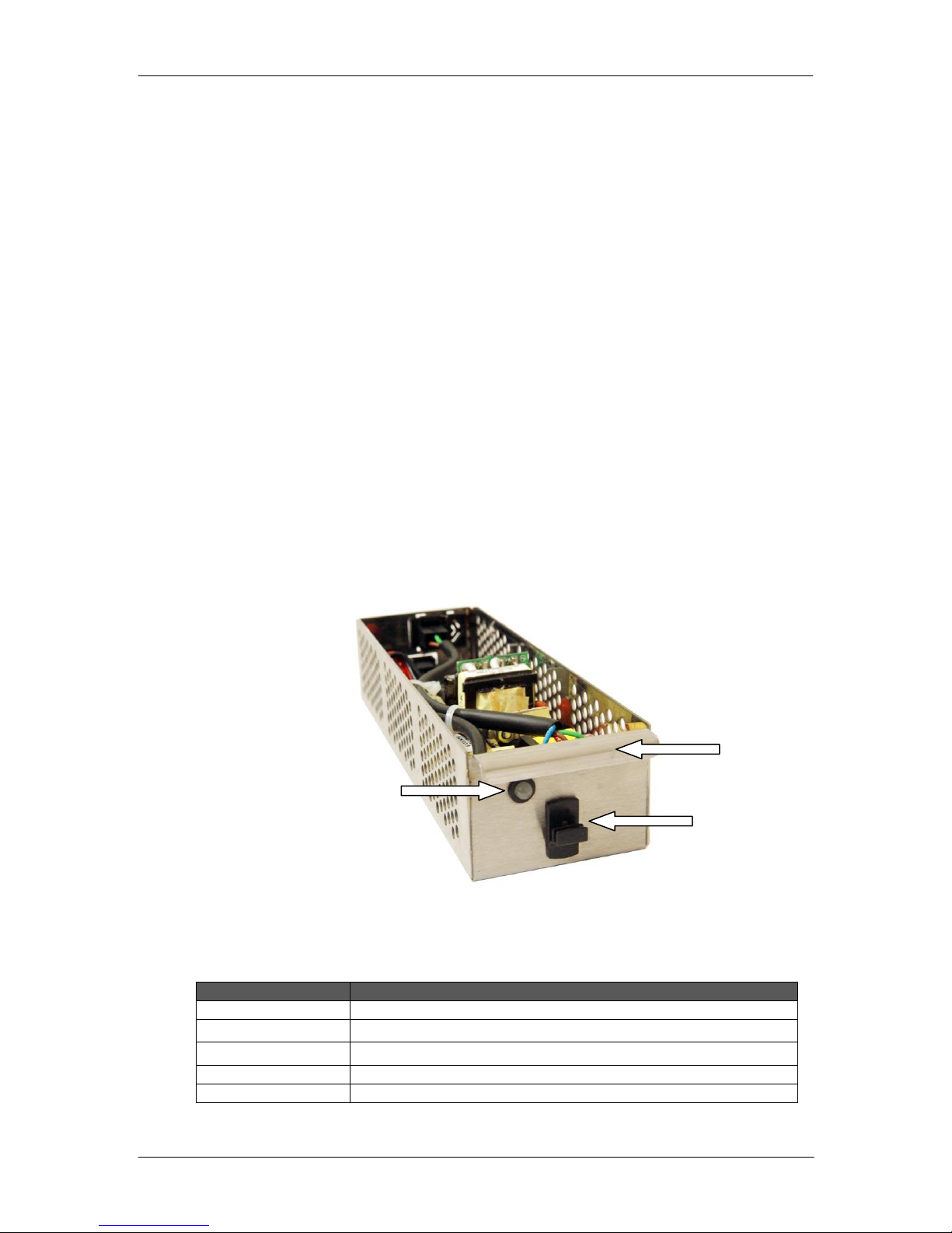
Alarm LED
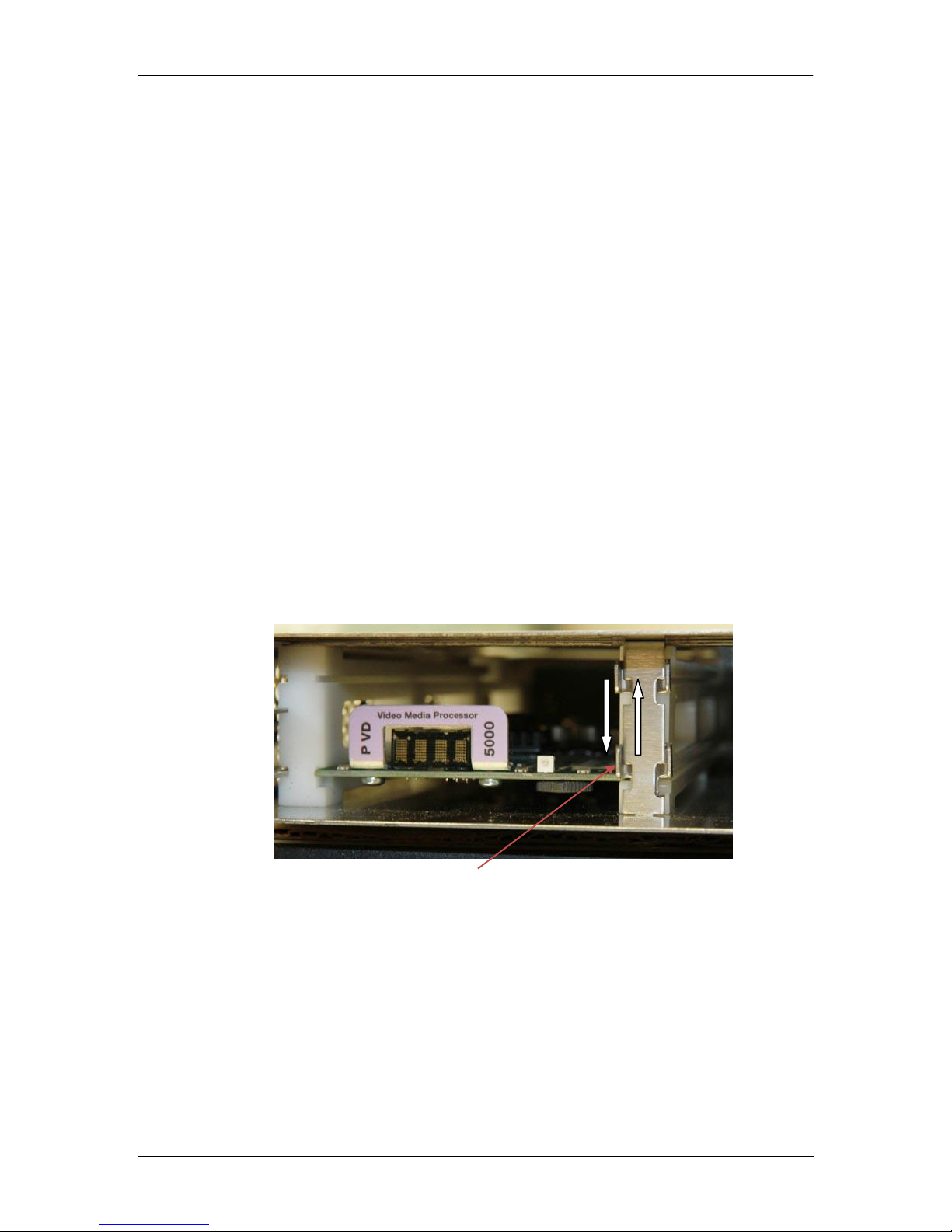
Locking Clip
Handle
The rack frame is designed to fit into industry standard 19” equipment housing. The chassis will
occupy 1 RU of rack space. Opening the front cover will allow access to the 19” rack mounting
holes.
Airflow is from side to side, therefore care needs to be taken not to restrict the airflow through the
system. There are no ventilation holes in the top of bottom of the chassis, and no additional rack
space is required to accommodate vertical airflow or ventilation.
Power Supply
The R FR 5041 includes the primary power supply (an optional external power supply
(RPS 5000) can be used for redundancy which will provide a +12VDC input). Should a
power fault develop, the errors are alarmed in the following ways:
Via the LED located on the front of the Power Supply (visible through front cover)
Via a GPO alarm connection to the Termination Panel
Via the LYNX Desktop Controller connected to the LAN port (if used)
If the external redundant power supply (Option RPS 5000) is used then the system will
switch supplies automatically in the event of primary supply failure; with no interruption to
system operation.
The primary power supply is installed and removed from the front of the rack. The supply
locks itself firmly in place. The power supply can be released by pushing up the locking
clip and pulling on the handle above (see below)
Power Supply Alarm LED
Page 10 of 34
Page 11
LED
Name
Color
Description
1
HotSync Write
green
HotSync switched ON
yellow
HotSync currently writing to device
off
HotSync switched OFF
2
HotSync Read
green
HotSync switched ON
yellow
HotSync currently reading from device
off
HotSync switched OFF
3
Network
green
network connected OK
yellow
DHCP mode active but not satisfied
off
network connection not active
4
Rack Fans
green
all rack fans OK
3 yellow flashes
saving current settings to local memory
red
rack fan failure
all LEDs flashing yellow:
LOCATE mode enabled by remote-interface
(for physical board identification)
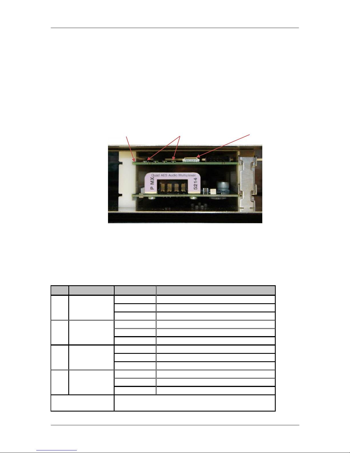
Status LEDs (1..4)
Rack Controller
Service Connection*
Rack Controller
The RFR 5041 is supplied with a integrated LAN rack controller, which when used with
the included LYNX Desktop Controller software application provides remote control,
status monitoring and alarm logging functionality. The 1RU rack can also be fully
integrated into larger systems which are using the LYNX Desktop Controller for
centralized control of a number of LYNX systems.
The rack controller is a fixed position in the rack, located above one of the available card
slots (the lower area of this slot can still be used for a LYNX module, no capacity is
removed). The controller can be removed if required for maintenance, simply slide
forward to unplug the module. Four LEDs are provided on the module edge which are
used to indicate status.
R FR 5041 Reference Manual. Rev 1.3
*Note. This connector is for use by LYNX Service personnel and is used for firmware updates to
the controller. Specialized programming equipment is required; do not attempt any connection to
this port.
Rack Controller Shown above Series 5000 Module in Chassis
Controller LED Indication
The controller status LEDs are used to indicate various conditions:
Page 11 of 34
Page 12
Slide retainer up to insert module, and down to lock into place
Module Installation
The R FR 5041 can accept 4 standard Series 5000 CardModules. There is no restriction
of type of module or function; any combination can be mixed as required. Some of the
more complex modules will require a double height backplane (for I/O reasons) and these
will occupy two slots.
If you ordered the R FR 5041 complete with modules then the chassis will be supplied
with the modules pre-installed and tested and the system is ready to be used. If you are
adding modules to the chassis yourself, then please follow the instructions below.
1. Unpack the CardModule from its shipping carton. The module is supplied with the
required backplane assembly. Please take static precautions when handling the
modules, as the modules are extremely sensitive to ESD.
2. Locate an empty slot in the R FR 5041 and remove the cover plate from the rear of
the rack in the corresponding position (2 screws).
3. Install the backplane onto the rack using the 2 screws provided.
4. Slide the CardModule into the corresponding rack slot from the front of the rack*, do
this slowly and ease into the rear connector. If this is difficult or requires excessive
force then please stop and check the rear panel installation. The module should be
fairly easy to slide into the rear connector.
*Note. Each module slot is equipped with a mechanical retainer which is used to prevent
the modules becoming unplugged in situations involving a lot of vibration (i.e. Mobile
applications). Slide the retainer up with your finger to access the module guide slot.
When the module is all the way in; slide the retainer back down to lock the module in
position. See below:
R FR 5041 Reference Manual. Rev 1.3
Page 12 of 34
Page 13
!
Push tab down to remove
Fuse carriage removed
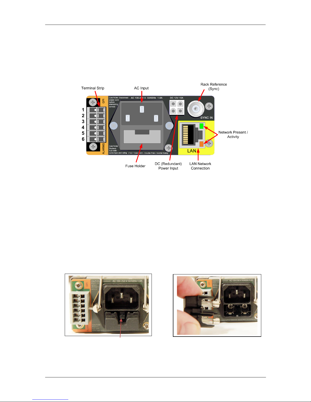
Rack Connections
Rear Termination Panel
The R FR 5041 has an integral termination panel on the rear of the rack for system
connections.
R FR 5041 Reference Manual. Rev 1.3
AC Input and Fuses
The AC input is auto sensing 100-250V 50/60Hz (1.8A nominal) and is located on the
rear of the chassis. Use a standard IEC power cord with a C13 connector for the power
connection. The fuses are located below the AC power input (see below). The system is
double pole / neutral fused so there are two fuses. The fuses are removed by pushing
down on the plastic tab and sliding the fuse carriage out. Insert new fuses and slide the
carriage back in all the way until the tab “clicks” and locks the fuse carriage in place.
Caution
Please remove power before attempting to exchange power fuses. Only replace
the fuse with a correctly rated replacement. (T2AH250V) For safety DO NOT
physically disconnect or isolate the rack from earth for any reason.
Fuse (x2) = T2AH250V
Page 13 of 34
Page 14

1 2 3 4 5
6
GPI B
GPI A
Alarm
Minor B
Alarm
Minor A
Alarm
Major B
Alarm
Major A
+12V
GND
1
2 3 4
Rack Reference (Sync Connector)
The chassis has a single reference input. This is for the connection of a “common rack
reference” which is distributed to each of the available rack slots for any installed
modules which require an external reference input.
The connection supports all analog SDTV and HDTV video sync standards (Auto-detect),
bi-level or tri-level.
Redundant Power Input
A connector is provided for the connection of an external 12VDC power input, which is
used for redundant protection. LYNX provides an optional RPS 5000 brick power supply
for use as an external redundant supply. If providing your own DC power input; then
please ensure a clean feed of +12VDC @ 8A (+/- 5%). The mating power connector is
Molex MiniFit Series 5557 (part # 0039012040), crimp contacts Molex Series 5556 (part #
0039000078). Connections are shown below.
R FR 5041 Reference Manual. Rev 1.3
External DC Input Connections
(View looking into connector)
Alarm Connection (Terminal Strip)
A terminal strip is provided for the connection to external alarm systems
The connections are designated as follows:
Function and connection information is described below.
Alarm Function
The user can assign the triggers for the alarm conditions using the LYNX Desktop
Controller Software Application.
The terminal strip has a GPI input (for future use), and two alarm outputs. These are
contact closures and allow for the connection of external monitoring equipment or alarm
systems.
There are two alarms Minor Alarm and Major Alarm, these are configured using the
LYNX Desktop Controller. Simply assign the alarms to the available selections.
Page 14 of 34
Page 15

R FR 5041 Reference Manual. Rev 1.3
When the alarm is triggered, a contact closure is made between the A and B
connections, for example a minor alarm will provide a contact closure between terminal
strip connector 3 and 4
Note. The default selection is “None” as shown above. Once the required settings have
been made they are stored in the rack controller and will survive power cycles.
LAN Connection (Remote Control)
The R FR 5041 is equipped with a rack controller and when using the LAN connection
remote control, status monitoring and alarm logging is possible when used with the
supplied LYNX Desktop Controller Software application.
The LAN connection is a standard TCP/IP connection at speeds up to 100MBit /
(10/100MBit) Full Duplex
Please refer to the Network Connection section of this manual for more details on the
LAN port configuration and use.
Hot Swapping
Power Supplies
All Series 5000 CardModules and Power Supplies are fully hot swappable.
Power Supply Failure
A failure in the Primary power supply will automatically trigger the use of the redundant
supply (if fitted) and will trigger the following alarm conditions / indications (requires
controller option).
Reported fault on the monitoring system
Alarm GPO trigger on the alarm connector (see Alarm Connections section)
Once identified, the defective supply can be removed and replaced with power connected
with no interruption to the operation of the CardModules [if the redundant supply is
installed].
CardModules
If a CardModule fails the error will be reported in the monitoring system (LYNX desktop
Controller Application) and via the front side alarm LED. Alarm function is module
dependant so please refer to the CardModule manual for failure conditions and
indications. The defective CardModule can be removed and replaced with an identical
replacement without removing power from the frame.
Page 15 of 34
Page 16

R FR 5041 Reference Manual. Rev 1.3
Fan 1
Fan 2
Power Supply Bracket
Fan
Fan
System Cooling and Fans
The chassis has integrated cooling fans and the airflow is from one side to the other
through the ventilation holes provided.
There is no ventilating through the top and bottom covers, so no space needs to be
allowed above and below the rack in a system installation.
Fan Replacement
The fans are monitored and alarmed in the control system; if a fan fails please follow the
instructions below to exchange fans.
The two fans are located on the right hand side of the chassis, each secured in place
using two screws.
1. Disconnect all cables and remove the chassis from the 19” rack frame.
2. Remove the top cover, screw locations to remove cover are shown below
3. Remove the power supply. To exchange the rear fan it will also be necessary to
move the power supply mounting bracket to one side (see below). Two screws in the
bottom of the chassis should be loosened to allow this bracket to be moved over.
Page 16 of 34
Page 17

R FR 5041 Reference Manual. Rev 1.3
4. Remove the 2 screws from the fans to take them from out of the chassis, unplug the
fan cables from the rear PCB
5. Insert new fans (ensure correct orientation) and plug leads into PCB.
6. Secure the power supply bracket and re-assemble chassis.
Note. Please contact LYNX Technik for replacement fan assemblies
Network Configuration
The R FR 5041 includes a LAN controller which when used in conjunction with the
supplied LYNX Desktop Controller software package will facilitate remote control, status
monitoring and error logging for all LYNX Hardware.
Connect the R FR 5041 to your network using the LAN port provided. The LEDs below
the LAN connector on the rack frame will show some network activity if connected
properly.
Note: The next steps require that you have already installed the LYNX Desktop Controller
on a client P. If this should not be the case please install the software. Refer to the software
installation instructions section of this manual.
Most configuration below have to be done by the network administrator. The default login and
default password for the administrator in the LYNX control system is:
- Login: admin
- Password: lynx$admin
The Network Connection Manager
Open the LYNX Desktop Controller application and select Tools>Network Connection
Management or click on the “Connect” button. (See below)
Page 17 of 34
Page 18

R FR 5041 Reference Manual. Rev 1.3
This will open the Network Connection Management Dialog shown below:
There are three tabs, one is for Serial connections (which are not applicable to the R FR
5041) and the other two are for network configuration. Please make sure the “simulation”
check box is unchecked
Note: Simulation mode will simulate a large LYNX installation and populate the system
with an array of simulated hardware for demonstration and training purposes. While this
will not impact the operation of any actual hardware connected, it is recommended to have
this turned off to avoid confusion.
Select the Network Connections Editor Tab. This dialog is shown below and comprises
of two main sections. The left hand side shows the current network configuration and the
right hand side shows the LYNX hardware which has been detected.
The LYNX software will automatically scan the network for any connected LYNX
hardware. All available devices will be displayed on the right hand side.
The R FR 5041 is shipped with a factory default IP address of 192.168.1.162. While
it’s certainly possible to use this IP address, it’s highly recommended to change this to
something suitable for your network. This can be set to a fixed static IP address or
automatically using DHCP if your network supports this.
If the R FR 5041 is not detected, then please check the network connection and network
activity using the LEDs on the connector. You can also manually enter the above IP
address and search specifically for this device.
In the example below you can see the LYNX GUI Computer in the current network
infrastructure with the detected R FR 5041 listed as an available network component with
the factory default IP address.
Page 18 of 34
Page 19

R FR 5041 Reference Manual. Rev 1.3
Configure IP Address
At this stage it’s recommended you configure the IP address of the R FR 5041 to
something suitable for your particular network, or configure DHCP. To do this click the
Network Component Configuration tab, see below:
Page 19 of 34
Page 20

R FR 5041 Reference Manual. Rev 1.3
When the device is selected you can manually change the IP address, or configure
dynamic IP (DHCP). To activate the text fields just click on the device.
Please contact your network administrator if you are not sure what static IP address to
use, or to get the required information to configure DHCP.
Setting IP Addresses
To set a dedicated IP address for the R FR 5041 just type in the required information into
the respective text fields in the Network Connection Management window shown above.
Note: DHCP mode has to be deactivated in the checkbox “Dynamic IP (DHCP)”
Activation of DHCP Mode
If the controller is installed in a network environment where the IP addresses are
allocated automatically (DHCP) the RFR5003/4 can be set to DHCP mode. Simply
activate the checkbox “Dynamic IP (DHCP)” in the Network Connection Management
window shown above.
Note: If in DHCP mode, the RFR 5003/4 will wait approx 30sec for a DHCP capable
server to allocate a IP address. If no address is allocated the default address will be used.
Note. It is possible for devices to have the same IP address and appear in this list (with
unique MAC addresses). This will cause a network error warning that duplicate IP
addresses are being used. Please ensure no duplicate IP addresses are present.
Network Attaching the R FR 5041
Once the IP address has been configured it is now necessary to move (connect) the R
FR 5041 into the network infrastructure so we can control and communicate with the
device. We do this by “attaching” the R FR 5041 to a control device (i.e. LYNX GUI or R
CT 5031)
To attach the R FR 5041 switch back to the “Network Connections Editor Tab”. Select
EDIT mode and drag&drop the R FR 5041 and place it under the LYNX GUI entry to
attach the R FR 5041 to the control system PC. See Below.
This drag and drop function has “attached” the R FR 5041 to the LYNX GUI, so it will now
be visible and accessible using the LYNX Desktop Controller.
Note. In larger installations
with additional LYNX
hardware present on the
network there may be RCT
5031 Rack Controllers
detected. It’s possible to
“attach” the R FR 5041 to an
existing RCT 5031 Controller
and still maintain full control
and visibility of the R FR 5041
in the control system. To
which control device to attach
the R FR 5041 is determined
by your installation and
control preferences and
network topology.
Page 20 of 34
Page 21

R FR 5041 Reference Manual. Rev 1.3
If you add additional R FR 5041 devices, these can also be attached in the same way to
control multiple devices.
LYNX Desktop Controller Software
The LYNX Desktop Controller software is supplied as part of the RFR 5003/4. This is
supplied on CD Rom or can be freely downloaded from the LYNX website.
The LYNX Desktop Controller is a comprehensive centralized application which provides
for the remote control / status monitoring and error reporting for all modules installed in a
system.
System Requirements
The control software is designed to run on a Windows compatible PC. Minimum
requirements specified below
Client PC
IBM compatible PC, Pentium 4 class, 256MB ram VGA Monitor, CD Rom drive with LAN
port.
Operating System:
Microsoft Win7, Microsoft Windows XP Home/Professional / SP2.
Software Installation
1. Close all other applications on the PC.
Insert the software CD into the CD-Rom drive. If the CD-Rom does not start
automatically, start the application from the CD by clicking on:
SetupLynxController.xxxxxxx.RELEASE_x.x.x.exe
2. The following dialog will display, read the license agreement and click I Agree if
acceptable.
Page 21 of 34
Page 22

R FR 5041 Reference Manual. Rev 1.3
3. Select the additional components and click Next
4. Define the destination folder and press Next to install the application. You can use
the proposed standard folder, which will be created automatically.
5. You can select the start folder menu and if you can choose if you would like an icon
placed on your desktop.
Page 22 of 34
Page 23

R FR 5041 Reference Manual. Rev 1.3
6. Installer will then start copying files to your hard drive. When finished Close the
Installer.
Starting the Controller Application
If you chose to install the desktop icon during installation, simply click this to start the
controller application.
LYNX Controller Icon.
OR navigate to the lynx folder in “program files” and select c3_local.exe
The GUI will start and the application will firstly look for attached LYNX controllers, when
found the controllers it will report all the attached modules into the GUI and these will
displayed in the folder tree. Module detection is automatic.
Software Updates
From time to time we update the software to add support for new modules or new
features or correct bugs. Updates are supplied free of charge. You can contact us directly
or check our web site (www.lynx-technik.com) for any available updates.
Software Version Number
To determine the release and version number
of the software installed on your system.
Pressing F1 or selecting the Help drop down
menu and then About will display the splash
screen.
Page 23 of 34
Page 24

1 2 3
4
Reporting Problems
If you are experiencing problems with your installation please contact us for assistance.
We will require a copy of a log file that is maintained by the system that can be found in
the C:\Program files\Lynx\C3_local directory. The file is called c3_local.logfile.txt.
We will ask you to E-Mail this file with a brief description of the problem and also any
steps we can use to duplicate the fault. Send messages to:
Support @ lynx-technik.com
Software Operation
The LYNX Control Software is intuitive and simple to use, presented in a familiar
Windows style layout. It is beyond the scope of this manual to provide detail on each
individual control available for all supported modules, please refer to the manuals of the
individual modules. This is intended as an introduction to the general layout and the use
of the control GUI.
R FR 5041 Reference Manual. Rev 1.3
Control System Layout
The above screenshot shows the normal layout of the control system GUI. The
descriptions below provide more detail on each section of the GUI and its operation.
Page 24 of 34
Page 25

1
Device List
This area is organized like a standard windows folder tree and is where all controllers and
modules detected by the system are displayed. The modules attached are arranged
under each controller.
By clicking with the right mouse button
on the selected module a pop up
window with additional controls for the
selected module will be shown.
R FR 5041 Reference Manual. Rev 1.3
Clicking on any device in the
folder tree will display the
associated GUI for control of
this device. Next to each
device there is a small
colored dot. This is a graphic
representation of the Alarm
LED next to each module
listed for easy identification of
problems within the system.
Levels can be collapsed and
expanded so only the
information required is
displayed in the folder tree.
This is useful for systems with
a large number of racks and
modules.
If a module is removed or
added to the system then this
will be detected automatically
and added / removed from
the folder tree. This also
triggers an event in the error
log (5) to indicate when this
change was made to the
system.
User Defined Device List
A user defined device can be created by each user.
Page 25 of 34
Page 26

R FR 5041 Reference Manual. Rev 1.3
Select the User Defined Device list in the
TAB “View”.
A second list, which can be edited, is now displayed. Select “Edit” mode (backgound
turns red) then you can drag&drop devices from the standard device list to the user
defined device list to create your own custom module groupings. Click save to exit the
edit mode and save the group.
Page 26 of 34
Page 27

Module Properties
Selecting Properties will give additional information about the module. This is
information which is also important in case of service issues
The Locate function is described below
R FR 5041 Reference Manual. Rev 1.3
New Control Window
New Control Window opens another window for control of the selected module.
With this function several control windows can be opened simultaneously showing
various control tabs.
Renaming Devices
Rename allows to change any module
name with a user defined description
Release will force the module to store all
current settings to be written into the onboard Flash memory
Note: After changing any parameter the
module will write the changes to the
Flash memory automatically after 10
seconds
To avoid any unwanted changes of settings all controls of the selected card can
be Locked. All control elements of this module are then grayed out.
If at any time it is necessary to return the module o the factory default settings this
can be done using the “Restore Factory Default” function. You will be prompted
if you are sure, as this will erase any stored information from the module flash ram
and set it back to the factory settings.
Page 27 of 34
Page 28
2
3
Simulation is only active when the simulation mode of the c3_local application is
selected
Module Title Area
This is the main title area where the description of the module can be found as well as
details on its physical location in the system (Rack number and Rack Slot)
This area also displays the status of the module and describes any reported error next to
the colored dot (which is also a mirror of the module LED)
Locate Function
For larger systems which may have multiple cards of the same type in a single rack, or
multiple racks in a larger system we have added a useful utility which will help to
physically locate a suspect module in a rack quickly.
When Locate is selected the status indicator on the GUI and the alarm LED will flash
yellow in the following continuous sequence.
3 short flashes…. Pause…. 3 short flashes …
The LED continues to flash in this way until the function is turned off in the GUI.
Use of the locate function will not interfere with the normal operation of the module.
R FR 5041 Reference Manual. Rev 1.3
Control Tabs
This is the main control area for the module and changes depending on which module is
selected in the folder tree. This area has several tabs that will take you into different
areas of control for the Module. The number of tabs will vary depending on the type of
module , for the controller you find Power Supply – Settings – Options – Params –
Events
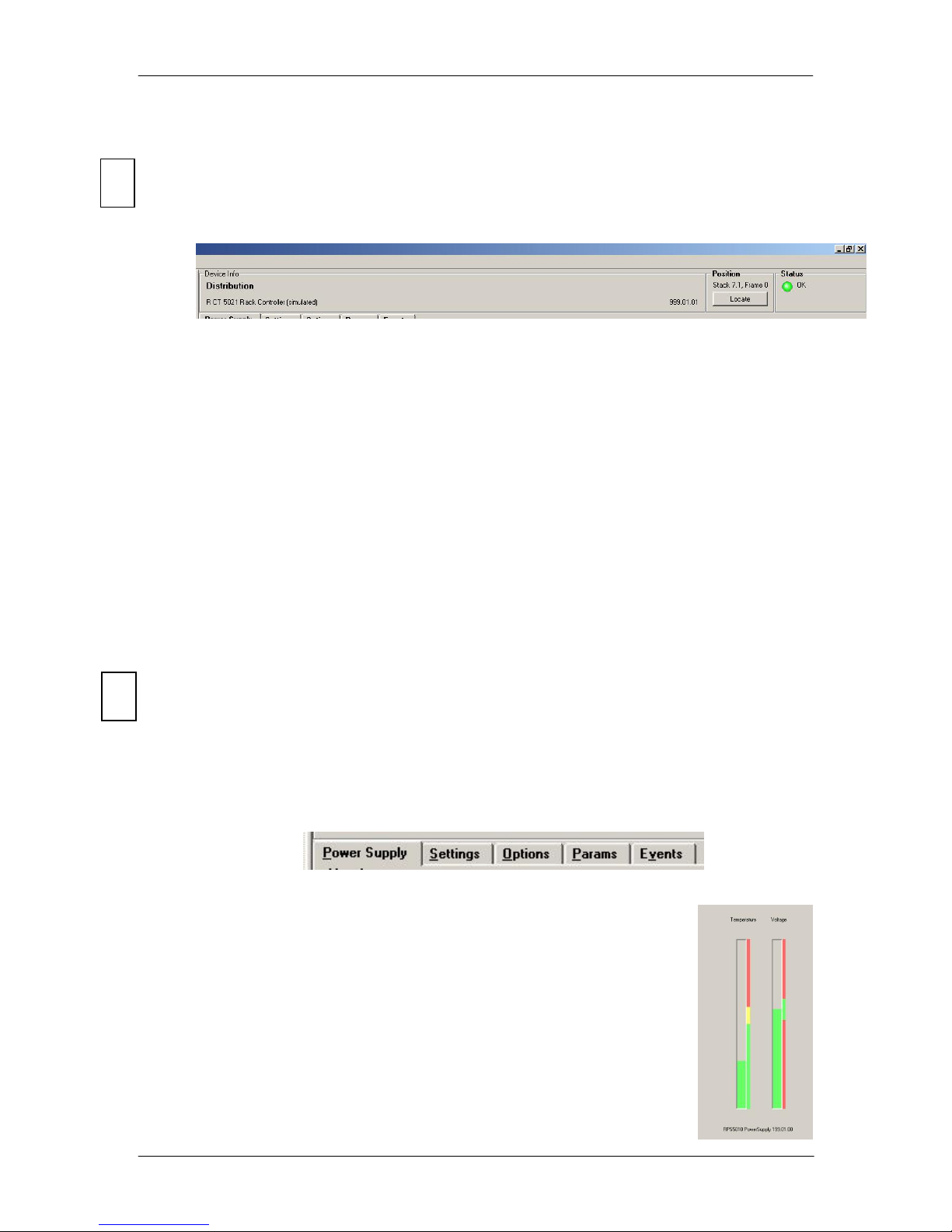
Power Supply Tab
This tab is the default display and brings up the primary controls for
the controller.
It shows the status of the power supply voltage as well as the
rack temperature
Page 28 of 34
Page 29
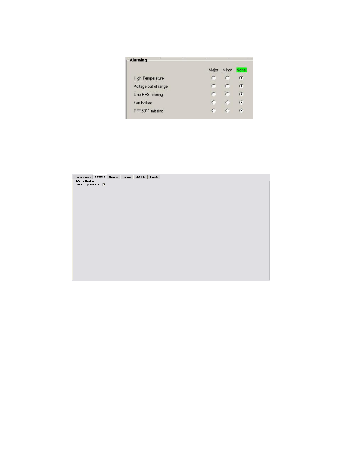
Alarms (two levels) for different failure modes in the rack frame can be set for
triggering of the GPO contacts.
Settings Tab
This tab allows for setting of the 10 “running LEDs” at the card front edge and the
activation of the function HotSync Backup. (Front panel LED settings not valid for
RFR 5003/4)
R FR 5041 Reference Manual. Rev 1.3
HotSync Backup
HotSync Backup is a feature built into the control system to store all module settings and
configurations to the R FR 5041 Controller. Currently all module settings are stored in
Flash Ram within the module which survive module removal / power cycles and even
long term storage. The HotSync Backup function supplements this with another level of
security.
Once enabled HotSync Backup will remember all the settings and configurations for all
modules installed in a R FR 5041 rack frame. This way when a defective module is “hot
swapped” the settings that were previously used are automatically written into the new
module. No switches to set, nothing to calibrate, simple plug and play convenience.
The HotSync function is totally automatic and runs in the background. This function
requires no user intervention once initially enabled in the GUI.
Page 29 of 34
Page 30

Switching on HotSync
The HotSync function is off by default and needs to be enabled in the control system
GUI. Highlight the R FR 5041 in the device browser and select the “Settings” tab. Here
you will see a checkbox to turn this function ON or OFF.
HotSync Function
The HotSync function has useful applications and below describes how the system works
under various situations
Board failure “Hot Swap’
Typically when a failure occurs it is important to get the system back online as quickly as
possible. Some LYNX modules are complex and have a lot of user settings and
configurations that have been set for a specific application. Having to manually reset all
the parameters in the new card can be time consuming and prone to errors. HotSync
takes care of this automatically. When the system detects a hot swap of a particular card,
HotSync will automatically restore all the previously used settings into the new module.
This process is automatic and takes a couple of seconds.
Note. A card of the same type must be exchanged for HotSync to function correctly.
System Changes
During normal operation the settings in the system can be changed or tweaked over time.
HotSync detects these changes when made and will automatically sync the revised
module data into its local memory. At all times the HotSync stored data is 100% up to
date – no user intervention is required.
Note. After a power cycle HotSync will not be functional for approx. 15 seconds. Any
modules hot swapped in this period will not be restored with the previous settings; the
specific module settings will be used.
R FR 5041 Reference Manual. Rev 1.3
Page 30 of 34
Page 31

Options Tab
One tab on the GUI is reserved for “Options“. This is where the option license codes are
entered to unlock the embedded firmware options.
R FR 5041 Reference Manual. Rev 1.3
If the module was purchased with options pre-installed then you will see the option status
as green (Active).
If you would like to add any option after delivery, then you will need to purchase the
specific license codes from LYNX Technik.
Click the “request code” button next to the channel you wish to activate. A number will be
displayed, Please forward this number with your purchase order to your authorized LYNX
dealer or representative. When you receive the license string simply type it (or paste it
using the windows clipboard) into the area provided and press “activate”.
Activation is confirmed when the option status turns green.
Page 31 of 34
Page 32

4
Events Tab
The Events Tab is where error notifications are configured for the module.
The GUI has an integrated error log, which
is a simple text log file stored in the
controller PC. This will record an event and
timestamp it. The log can be seen at the
bottom of the GUI screen and can be
scrolled through using the scrolling bar.
Events are always logged into
c3_local.logfile.txt. The checkboxes (see
screenshot below) enable or disable the
display of error messages to the GUI log
window (see below: Error Logging Area),
saving to the logfile cannot be disabled.
R FR 5041 Reference Manual. Rev 1.3
Log in GUI Function
Events are selectable, you can chose if you want to record a particular event in the log
(or not) or configure it to only record one side of the event. (For example you might want
to log when a power supply is missing but do not want to log when it came back). The
ON/OFF trigger can be configured for each of the available events shown in the list and is
setup using the checkboxes provided.
SNMP Support
If the RFR 5003/4 is “attached” to a RCT 5031 Master Controller (in network
configuration) and the SNMP option is installed on the RCT 5031, then the “SNMP Trap”
columns become available.
Here you can configure what events you would like to transmit a “SNMP trap” for over the
network. (This has no impact or influence over the internally error log maintained by the
LYNX control system)
(Internal LYNX error logging and external SNMP traps can be configured independently).
Note. The simulated event is part of the GUI simulator and allows us to force a
particular error condition for testing and demonstration purposes.
Error Logging Area
This is the error logging area of the GUI and is the central repository of all errors
encountered by the system.
Note. The messages in the log window can be erased, but a log file is stored in
the PC not the individual modules. Each time an error condition is encountered
and entry is automatically made in the log. All entries are time stamped and can
be sorted in any of the columns provided by clicking on the column headers.
Page 32 of 34
Page 33

Mechanical
Size
1 RU high x 350 mm deep including connectors and front cover.
Standard 19” rack mount.
Weight (empty)
4.5 kg with single power supply and controller
Connections
All connections made on rear of rack
Performance
Available Card Slots
4 x Series 5000 CardModules (single width backplanes)
Power Supplies
1 x Power Supply (primary - included)
Power Indication (alarm)
One multifunction LED on Supply and GPO output
Controller alarm
Multifunction LED (internal)
Connections (rear connections)
LAN Connector
RJ 45 (10/100 Base T) Full Duplex
Alarm Connector
Terminal strip
Alarm Major and Minor: Relay contact closures
Ref In
BNC connection for rack reference
Analog Bi-level or Tri-level Sync (auto detect)
Primary AC
Standard IEC 60320 C13 AC power connector,
double pole fused (2A) # T2AH250V
External Redundant Power input
12VDC 8A (use R PS 5000 optional power brick)
Electrical Specifications
Power Input
100 – 240VAC, 50Hz – 60Hz.
Power Consumption
100 W max.
Safety
IEC 60950/ EN 60950/VDE 0805
Ambient
Temperature
5°C to 40°C Maintaining specifications
0°C to +50°C Operating
Humidity
Max 90% (non condensing)
Supplied Accessories
Documentation
Reference Manual (CD)
Software
LYNX Desktop Controller Software (CD)
Specifications
R FR 5041 Reference Manual. Rev 1.3
Page 33 of 34
Page 34

®
Service
R FR 5041 Reference Manual. Rev 1.3
Technical Support
If you are experiencing problems, or have questions please contact your local distributor
for further assistance.
Technical support is also available from our website.
Please DO NOT return products to LYNX Technik without an RMA. Please contact your
authorized dealer or reseller for more details.
More detailed product information and product updates may be available on our web site:
www.lynx-technik.com
Contact Information
Please contact your local distributor; this is your local and fastest method for obtaining
support and sales information.
LYNX Technik can be contacted directly using the information below.
Address LYNX Technik AG
Brunnenweg 3
D-64331 Weiterstadt
Germany
Website www.lynx-technik.com
E-Mail info@lynx-technik.com
LYNX Technik manufactures a complete range of high quality modular products for
broadcast and Professional markets, please contact your local representative or visit our
web site for more product information.
LYNXTechnik AG
Broadcast Television Equipment
Page 34 of 34
 Loading...