

Page 1
Page 2

OPERATOR’S MANUAL LYNX 2008
Adventure V-800
Ranger V-800
Ranger 550
SAFETY WARNING
Disregarding any of the safety precautions and instructions contained in this
Operator’s Guide, or on-product warnings may result in injury, including the
possibility of death.
This Operator’s Guide should remain with the unit at time o f resale.
LYNX products are manufactured by BRP.
Bombardier* Lite
* Trademark of Bomb ardier Inc. used under license.
The following a re trademarks of Bombardier Rec re ational Products Inc. or its
subsidiaries.
LYN X
®
RER
TM
RF™
SC™
ROTAX
TM
Pilot™ TRA™
DESS™
Printed in Canada. (mmo2008-RF HT)
®™ and the BRP logo are trademarks of Bombardier Recreational Products Inc. or its affiliates.
©2007 Bombardier Recreational Products Inc. and BRP US Inc. All rights reserved.
* Trademark of Bombardier Inc. used under license.
Page 3

FOREWORD
Congratulations on your purchase of
a new LYNX snowmobile. Whatever
model you have chosen, it is backed
by the Bombardier Recreational Products. (BRP) warranty and a netw ork of
authorized LYNX snowmobile dealers
ready to provide the parts, s ervice or
accessories you may require.
The Operator's Guide has been prepared to acquaint the owner/operator
and passenger with this new snowmobile and its various controls, maintenance and safe riding instructions.
This guide is indispensable for the
proper use of the product and should
be kept with this snowmobile at all
times.
Make sure you read and understand
the content of this Operator's Guide.
After reading, please keep this Operator's Guide with the snowmobile. If
the snowmobile is resold, please give
the guide to the new owner for his
awareness.
Also note that the guide is available in
several languages.
If you have any question regarding any
topic wh ether or not it is covered in
this Operator's Guide, please contact
your Dealer.
This guide uses the following safety
alert symbol in conjunction with signal
words to indicate a potential personal
injury hazard.
WARNING
Indicates a potentially hazardous
situation which, if not avoided,
could result in death or serious
injury.
CAUTION
Indicates a potentially hazardous
situation which, if not avoided,
may result in minor or moderate
injury. When used without the
safety alert symbol ,potential
hazard exists for property damage
only.
NOTE: Indicates supplementary infor-
mation needed to fully complete an instruction.
WARNING
2-UP vs 1-UP models:
Throughout this Operator's Guide,
the term “1-UP” refers to vehicles
designed to carry the operator only while the term “2-UP” refers to
vehicles designed to carry also a
passenger.
Make sure to identify and follow
the warnings and instructions that
are applicable to your specific
model.
Although the mere reading of such information does not eliminate the hazard, the understanding and application
of the information will promote the
correct use of the vehicle.
Your dealer is committed to your satisfaction. He has taken training to perform the initial set-u p and in s pection
of your snowmobile as w ell as completed the final adjustment required
to suit your specific weight and riding
environment before you took possession. At delivery, your dealer would
have explained the snowmobile controls and provided you with a brief
explanation of the various suspension
adjustments. We trust you have taken full advantage of this!
______________________
1
Page 4

At delive ry, you were also informed
of th e warranty coverage and have
completed the Warranty Registration
process.
The information and components/
system descriptions contained in this
guide are correct at time of publication. BRP, however maintains a
policy of continuous improvement of
its products without imposing upon
itself any obligation to install them on
products previously manufactured.
Because of its ongoing commitment
to product quality and innovation, BRP
reserves the right at any time to discontinue or change specifications, designs, features, models or equipment
without incurring oblig atio n.
The illustrations in this document
show the typical construction of the
different assemblies and, in all cases,
may not reproduce the full detail or
exact s hape of the parts shown, however, they represent parts which have
the same or a similar function.
It is understood that this guide may
be translated into another language.
In the event of any discrepancy, the
English version shall prevail.
Specifications are given in the SI metric system. Where precis e accuracy
is not required, some conversions are
rounded off for easier use.
Most components of this snowmobile
are built with parts dimensioned in the
metric system. Most fasteners are
metric and must not be replaced by
customary fasteners or vice versa.
We recommend genuine BRP products for replacement parts and accessories. They've been specially
designed for your vehicle and manufactured to meet BRP's demanding
standards.
For any questions pertaining to the
warranty and its application, consult
the WARRANTY section in this guide,
and/or an authorized LYNX dealer.
2
_______________________
Page 5

TABLE OF CONTENTS
SAFETY INFORMATION
INTRODUCTION ..................................................................... 8
IMPORTANT BASIC SAFETY MEASURES....................................... 9
LAWS AND REGULATIONS....................................................... 13
RIDING THE VEHICLE.............................................................. 14
Principle of Operation .......................................................... 14
How to Ride ..................................................................... 14
Carrying a Passenger ........................................................... 16
Terrain/Riding Variations........................................................ 18
Transporting and Towing ....................................................... 22
TRACTION ENHANCING PRODUCTS........................................... 23
SAFETY LABELING................................................................. 27
ENVIRONMENT INFORMATION
GENERAL ............................................................................ 34
JUST WHAT IS LIGHT TREADING? ............................................. 35
WHY IS LIGHT TREADING SMART.............................................. 36
VEHICLE INFORMATION
HOW TO IDENTIFY YOUR SNOWMOBILE ..................................... 38
CONTROLS/INSTRUMENTS/EQUIPMENT .................................... 40
1) Speedometer................................................................. 41
2) Tachometer ................................................................... 43
3) Pilot Lamps ................................................................... 43
4) Throttle Lever ................................................................ 43
5) Brake Lever................................................................... 43
6) Parking Brake Lever ......................................................... 43
7) Multi-Function Switch ....................................................... 44
8) Handlebar ..................................................................... 45
9) Ignition Switch ............................................................... 45
10) Tether Cut-Out Switch ..................................................... 46
11) Engine Cut-Out Switch .................................................... 47
12) Rewind Starter Handle..................................................... 47
13) Choke Lever ................................................................ 47
14) Fuel Tank Cap/Gauge....................................................... 48
15) Windshield .................................................................. 48
16) Hood and Side Panel Latches............................................. 48
17) Fuses ........................................................................ 49
18) Front Grab Handle/Front Bumper ......................................... 51
______________________
3
Page 6

19) Storage Compartment ..................................................... 52
20) Rear Rack ................................................................... 52
21) Tool Kit....................................................................... 52
22) Spark Plug Holder .......................................................... 52
23) Spare Drive Belt Compartment ........................................... 53
24) Hitch ......................................................................... 53
25) Shields and Guards......................................................... 53
26) Track ......................................................................... 53
27) Holding Strap ............................................................... 53
28) Rear Grab Handles ......................................................... 54
29) Adjustable Mirrors.......................................................... 54
30) Backrest ..................................................................... 54
31) Gear Shift Lever ............................................................ 54
32) Seat Strap ................................................................... 54
RECOMMENDED FUEL AND OIL ................................................ 55
BREAK-IN PERIOD.................................................................. 57
OPERATING INSTRUCTIONS..................................................... 58
Pre-Operation Check ........................................................... 58
Engine Starting Procedure (2-Stroke) ......................................... 59
Engine Starting Procedure (4-Stroke) ......................................... 60
Vehicle Warm-Up ............................................................... 61
Shutting Off the Engine ........................................................ 61
Post-Operation Care ............................................................ 61
Suspension Adjustments ...................................................... 61
SPECIAL OPERATING INSTRUCTIONS ......................................... 67
Riding at High Altitudes or Sea Level......................................... 67
Riding in Cold Weather......................................................... 67
Emergency Starting............................................................. 67
Towing an Accessory........................................................... 68
Towing Another Snowmobile.................................................. 68
Transporting the Vehicle........................................................ 68
TROUBLESHOOTING .............................................................. 70
SPECIFICATIONS ................................................................... 73
MAINTENANCE INFORMATION
PERIODIC MAINTENANCE CHART .............................................. 80
2-STROKE............................................................................ 81
4-STROKE............................................................................ 84
ENGINE SYSTEM................................................................... 87
Air Filter Cleaning ............................................................... 87
Coolant Level.................................................................... 87
Exhaust System................................................................. 88
Injection Oil Level............................................................... 88
Engine Oil Level................................................................. 89
Engine Oil/Oil Filter Change ................................................... 89
4
_______________________
Page 7

DRIVE SYSTEM..................................................................... 91
Belt Guard Removal and Installation.......................................... 91
Brake Fluid Level................................................................ 92
Brake Condition ................................................................. 93
Brake Adjustment............................................................... 93
Chaincase Oil Level............................................................. 93
Chaincase Oil Change .......................................................... 94
Drive Chain Tension ............................................................ 94
Drive Belt Condition ............................................................ 94
Drive Belt Removal/Installation................................................ 94
Drive Belt Height Adjustment ................................................. 96
Drive Pulley Adjustment ....................................................... 98
Track Condition.................................................................. 99
Track Tension and Alignment ................................................ 100
ELECTRICAL SYSTEM ........................................................... 103
Battery Electrolyte ............................................................ 103
REAR SUSPENSION ............................................................. 104
STEERING AND FRONT SUSPENSION....................................... 105
BODY/FRAME..................................................................... 106
Vehicle Cleaning and Protection............................................. 106
Bulb Replacement ............................................................ 106
Headlamp Beam Aiming ..................................................... 107
STORAGE AND PRESEASON PREPARATION ............................... 108
WARRANTY
BRP FINLAND OY INTERNATIONAL LIMITED WARRANTY: 2008 LYNX
®
SNOWMOBILES .................................................................. 110
PRIVACY OBLIGATIONS/DISCLAIMER ....................................... 113
CHANGE OF ADDRESS/OWNERSHIP ........................................ 114
______________________
5
Page 8

6
_______________________
Page 9

SAFETY
INFORMATION
____________
SAFETY INFORMATION
____________
7
Page 10

INTRODUCTION
Everyone is a beg in ner the first time
he sits behind the controls of a snowmobile regardless of previou s experience in driving an automobile, a
motorcycle or a motorboat. The safe
use of your snowmobile is dependent
on many condition s such as visibility,
speed, weather, environment, traffic,
vehicle condition and the condition of
the driver.
Each operator has a resp onsibility to
ensure the safety of his/her passenger, if any, and of other recreationists
or bystanders.
You are responsible for proper operation of your vehicle as well as training
thosewhomyouallowtorideordrive.
There may be noticeable handling and
performance differences from one
snowmobile to the other.
A snowmobile is relatively simple to
operate but like any other vehicle
or mechanical equipment, it can be
hazardous if you or a passenger are
reckless, thoughtless or inattentive.
We encourage you to have an Annual
Safety Inspection of yo ur snowmobile. Please contact an authorized
LYNX dealer for further details. Finally, we urge you to visit an authorized
LYNX dealer periodically for regular
and safety maintenance, as well as
snowmobile accessories you may require.
8
____________
SAFETY INFORMATION
___________
Page 11

IMPORTANT BASIC SAFETY MEASURES
Training
Basic training is required for the
safe operation of any snowmobile.
Study your Operator's Guid e paying
particular attention to cautions and
warnings. Join your local snowmobile club: its social activities
and trail systems are planned for
both fun and safety. Obtain basic
instructions from your snowmobile
dealer, friend, fello w club member
or enroll in your state or provincial
safety training program.
Always show a new operator how
to s ta rt and stop the vehicle. Indicate the correct riding positions
and, above all else, only allow him
to operate the snowmobile in a restricted flat area — at least until he
is co m pletely fa miliar with its o p eration. If there is a local snowmobile
operator's training course existing,
have him enroll.
Performance
The performance of some snow-
mobiles may significantly exceed
that of other snowmobiles you have
operated. Therefore, use by novice
or inexperienced operators is not
recommended.
Snowmobiles are used in many
areas and in m any snow conditions. Not all models perform the
same in similar conditions. Always
consult your snowmobile dealer
when selecting the snowmobile
model for your particular needs and
uses.
Injury or death may result to the
snowmobile operator, passenger
or bystander if the snowmobile is
used in risky conditions which are
beyond the driver's, passenger's
or snowm o b ile's capabilities or intended use.
Age
BRP recommends the operator has
at least 16 years old of age. NOTE!
Follow your local regulation !
Speed
Speeding can be fatal. In many
cases, you cannot react or respond
quickly enough to the unexpected.
Always ride at a speed which is
suitable to the trail, weather conditions and your own ability. Know
your local rules. Speed limit may
be in effect and meant to be observed.
Riding
Always keep right hand side of the
trail.
Always keep a safe dista nc e
from other snowmobiles and bystanders.
Remember, promotional material
may show risky maneuvers performed by professional riders under
ideal and/or c ontrolled conditions.
You should never attempt any such
risky maneuvers if they are beyond
your level of riding ability.
Never ride after consuming drugs or
alcohol or if you feel tired o r ill. Operate your snowmobile prudently.
Your snowmobile is not designed to
be operated on public streets, roads
or highways.
Snowmobiling at night can be a de-
lightful experience but because o f
reduced visibility, be extra cautious.
Avoid unfamiliar terrain and be sure
your lights are working. Always carry a flashlight and spare light bulbs.
____________
SAFETY INFORMATION
___________
9
Page 12

Nature is wonderful but don't let it
distract your attention from driving.
If you want to truly appreciate winter's scenery, stop your snowmobile on the side of the trail so t h at
you don't become a hazard to others.
Fences represent a very serious
threat for both you and your snowmobile. Give a wide berth to telephone poles or posts.
Hidden wires unseen from a dis-
tance can cause serious accidents.
Always wear an approved safety
helmet, eye protection and a face
shield. This also applies to your
passenger.
Be aware of inherent risks associ-
ated with riding off trails, such as
avalanche and other natural or man
made hazards or obstacles.
Avoid road traveling. If you must
do so, and it is permitted, reduce
speed. The snowmobile is not designed to operate or turn on paving.
When crossing a road, make a full
stop, then look carefully in both directions before crossing at a 90° angle. Be wary of parked vehicles.
Tailgating another sn owmobile
should be avoided. If the snowmobile in front of you slows for any
reason, its driver and passenger
could be harmed through your neglect. Maintain a safe stopping
distance between you and the
snowmobile in front of you. Depending on the terrain condition,
stopping may require a little more
space than you think. Play it safe.
Be prepared to use evasive driving.
Venturing out alone with your snow-
mobilecouldalsobehazardous.
You could run out of fuel, have an
accident, or damage your snowmobile. Remember, your snowmobile
is capable of traveling further in half
an hour than you may be able to
walk in a day. Use the “buddy system”. Alway s ride with a friend or
member of your snowmobile club.
Even then, tell someone where you
are going and the approximate time
you plan to return.
Meadows sometimes have low ar-
eas where water accumulate and
freezes over in winter. This ice is
usually glare ice. Attempting to
turn or brake on this surface could
cause your vehicle to spin out of
control. Never brake or attempt
speeding or turning on glare ice. If
youdohappentotraveloversuch
a condition, reduce speed by carefully releasing the throttle.
Never “jump” with your snowmo-
bile. This should be left to professional stunt men. Don't show off.
Be responsible.
While on safari, do not “gun” the
throttle. Snow and ice can be
thrown back into the path of a
following snowmobile. In addition,
when “gunning” the throttle, the
vehicle digs into and leaves an irregular sn o w surface for others.
Safaris are both fun and enjoyable
but don't show off or overtake
others in the group. A less experienced operator might try to do the
same as you and fail. When riding
with others, limit your abilities to
the experience of others.
10
___________
SAFETY INFORMATION
___________
Page 13

Operation
Always make a pre-start inspection
BEFORE you turn on the ignition.
In an emergency, the snowmobile
engine can be stopped by activating
the engine cut-out s w itch, pulling
the tether cord cap or turning off the
key.
Throttle mechanism should be
checked for free movement and
return to idle position before starting engine.
Always engage parking brake when
vehicle is not in use.
Never run the engine in a non-
ventilated area and/or if vehicle is
left unattended.
Never operate the engine without
belt guard securely installed or,
with hood or access/side panels
open or removed. Never run the
engine without drive belt installed.
Running an unloaded engine such
as without drive belt or with track
raised, can be dangerous.
Electric start models only: Never
charge or boost a battery while installed on snowmobile.
Ensure the path behind is clear of
obstacles or bystanders before proceeding in reverse.
Do not leave your keys in the ig-
nition switch, it is a n invitation to
thieves and a danger to young children.
Raising the rear of your snowmobile
while the engine is running could
cause snow, ice or debris to be
thrown back at an observer. Never raise the rear of th e vehic le while
the engine is running. To clear or inspect the track, stop the engine, tilt
thevehicleonitssideandremove
blockage with a piece of wood or
branch. Never allow anyone near a
rotating snowmobile track.
Maintenance
Know your snowmobile and treat
it with the respect and care due of
any power driven machine. Common sense, proper handling and
routine maintenance will result in
safer and enjoyable use.
Only perform procedures as de-
tailed in this guide. Unless otherwise specified, engine should be
turned OFF and cold for all lubrication, adjustment and maintenance
procedures.
Never have the engine running
whilethehoodisopen. Evenat
idle, a snowmob ile engine is turning around 1,800 revolutions per
minute. Always turn off the ignition before opening the hood for
any reason.
Never remove any original equip-
ment from your snowmobile. Each
vehicle has many built in safety features. Such features include various guards and console s, plus reflective materials and warning labels.
A poorly maintained snowmobile
itself can b e a potential haza rd. Excessively worn components could
render the vehicle completely inoperative. Keep the snowmob ile
in good working condition at all
times. Follow your pre-operation
check, weekly, monthly and annually routine maintenance and
lubrication procedures as detailed
in this guide. Consu lt a snowmo bile dealer or acquire a shop manual
and proper tools and equipment if
other repairs or service is required.
Do not stud the track unless it as
been approved for studs. At speed,
a s tudded track that as not been
approved for studs could tear and
separate from vehicle posing a risk
of severe injury or death.
____________
SAFETY INFORMATION
___________
11
Page 14

Fuel
Always stop the engine before
refueling. Fuel is flammable and
explosive under certain conditions.
Always work in a we ll-ve ntilated
area. Do not smoke or allow open
flames or sparks in the vic inity.
Open cap slowly. If a differential pressure condition is noticed
(whistling sound heard when loosening fuel tank cap) have vehicle
inspected and/or repaired before
further operation. Do not overfill
or top off the fuel tank before placingthevehicleinawarmarea.
As temperature increases, fuel expands and might overflow. Always
wipe off any fuel spillage from the
vehicle. Periodically verify fuel system.
Basics for Passenger
Never ride as a passenger unless
the snowmobile is equipped with a
passenger seat, and sit only on the
designated passenger seat.
A lwa ys wear a DOT approved hel-
met and follow the same dressing
guidelines as those recommended
for the operator and described in
this guide.
M ake sure that you are able to
achieve a stable stance, both feet
resting positively on the footboards
of footrests with good grip, and
that you are able to hold on firmly
to the handholds.
Once underway, if you feel uncom-
fortable or insecure for any reason,
don‘t wait, tell the driver to slow
down or stop.
12
___________
SAFETY INFORMATION
___________
Page 15

LAWS AND REGULATIONS
Know your local laws.
Federal, state, provincial and local gov-
ernment agencies have enacted laws
and regulations pertaining to the safe
use and operation of snowmobiles. It
is your responsibility as a snowmobiler
to learn and obey these laws and regulations. Respect and observance will
result in safer snowmobiling for all.
Be aware of the liability property damages and insurance laws regarding
your equipment.
____________
SAFETY INFORMATION
___________
13
Page 16

RIDING THE VEHICLE
Before venturing on the trails, operate
the snowmobile in a restricted flat area
until you are completely familiar with
its operation and feel comfortable that
you can safely tackle a more demanding task. Have an enjoyable and safe
ride.
Principle of Operation
Propulsion
Depressing throttle lever increases
engine RPM causing th e drive pulley
to engage. Depending on models engine RPM must be between 2500 and
4200 before drive pulley engagement
will occur.
Outer sheave of drive pulley moves
toward inner sheave, forcing the drive
belt to move upward on the drive
pulley and simultaneously forcing the
sheaves apart on the driven pulley.
The driven pulley senses the load on
the track and limits the belt movement. The result is an optimized
speed ratio between engine RPM and
the speed of the vehicle at any time.
WARNING
Never operate engine without belt
guard securely installed or, with
hood or access/side panels open
or removed.
Power is transferred to the track
through the chaincase or gearbox
and drive axle.
WARNING
Always use a wide-base snowmobile mechanical stand to properly
support vehicle during any track
verification. Slowly accelerate
engine in order to rotate track at
very low speed when it is not on
ground.
Tur nin g
Handlebar controls the steering of the
vehicle. As the handlebar is rotated to
right or left, the skis are turned right or
left to steer the snowmobile.
Stopping
Before riding your snowmobile, you
should understand how to stop it.
This is done by releasing the throttle
and gradually depressing the brake
lever on the left side of the handlebar.
In an emergency, you may stop your
vehicle by pressing the engine cut-out
switch located near the throttle control
and applying the brake. Remember, a
snowmobile cannot “stop on a dime”.
Braking characteristics vary with deep
snow, packed snow or ice. If the track
is locked during hard braking, skidding
may result.
How to Ride
How to Dress
Proper snowmobile clothing should
be worn. It should be comfortable
and not too tight. Always check the
weather forecast before going on a
ride. Dress for the coldest weather
expected. Thermal underwear next
to the skin also provides a good insulation.
DOT approved helmets are recommended at a ll times. They provide
both warmth a nd reduce injury. A
stocking type cap, balaclava and face
mask should always be carried or
worn. Goggles or a face shield that
attach to the helmet are indispensable.
Hands should be p rotected by a pair
of snowmobile gloves or mitts which
have sufficient in su latio n and allow
use of thumbs and fingers for operation of controls.
14
___________
SAFETY INFORMATION
___________
Page 17
Rubber bottom boots with either a nylon or a leather top, with removable
felt liners are best suited for snowmobiling.
You should keep yourself as dry as
possible when snow m obiling. When
you come indoors, take your snowmobile suit and boots off and make certain they dry properly.
Do not wear long scarfs and loose apparels that could get caught in moving
parts.
What to Bring
Every snowmobiler should carry at
least the follow ing basic parts and
tools that can help him and others in
an emergency:
• this Operator's Guide
• spare spark plugs and wrench
•frictiontape
• spare drive belt
• spare starter rope
• spare light bulbs
• tool kit (including at least p liers,
screwdriver, adjustable wrench)
•knife
• flashlight.
Include other items depending on the
length and time of your ride.
Riding Position
Your riding position and balance are
the two basic principles of making
your snowmobile go where you want
it to. When turning on the side of a
hill, you and your passenger must be
ready to shift body weight to help it
turn in the desired direction. Driver
and passenger(s) must never attempt
this maneuvering by placing feet outside of the vehicle. Experience will
teach you how much lean to put into turns at different speeds and how
much you will have to lean into a slope
to maintain proper balance.
Generally, the riding position for best
balance and control is sitting. However, the posting, kneeling or standing
positions are also used under certain
conditions.
The novice driver should become familiar with the snowmobile throu g h
practice on a level area at slow speeds
before venturing afield.
WARNING
Do not attempt any maneuvers if
they are beyond your abilities.
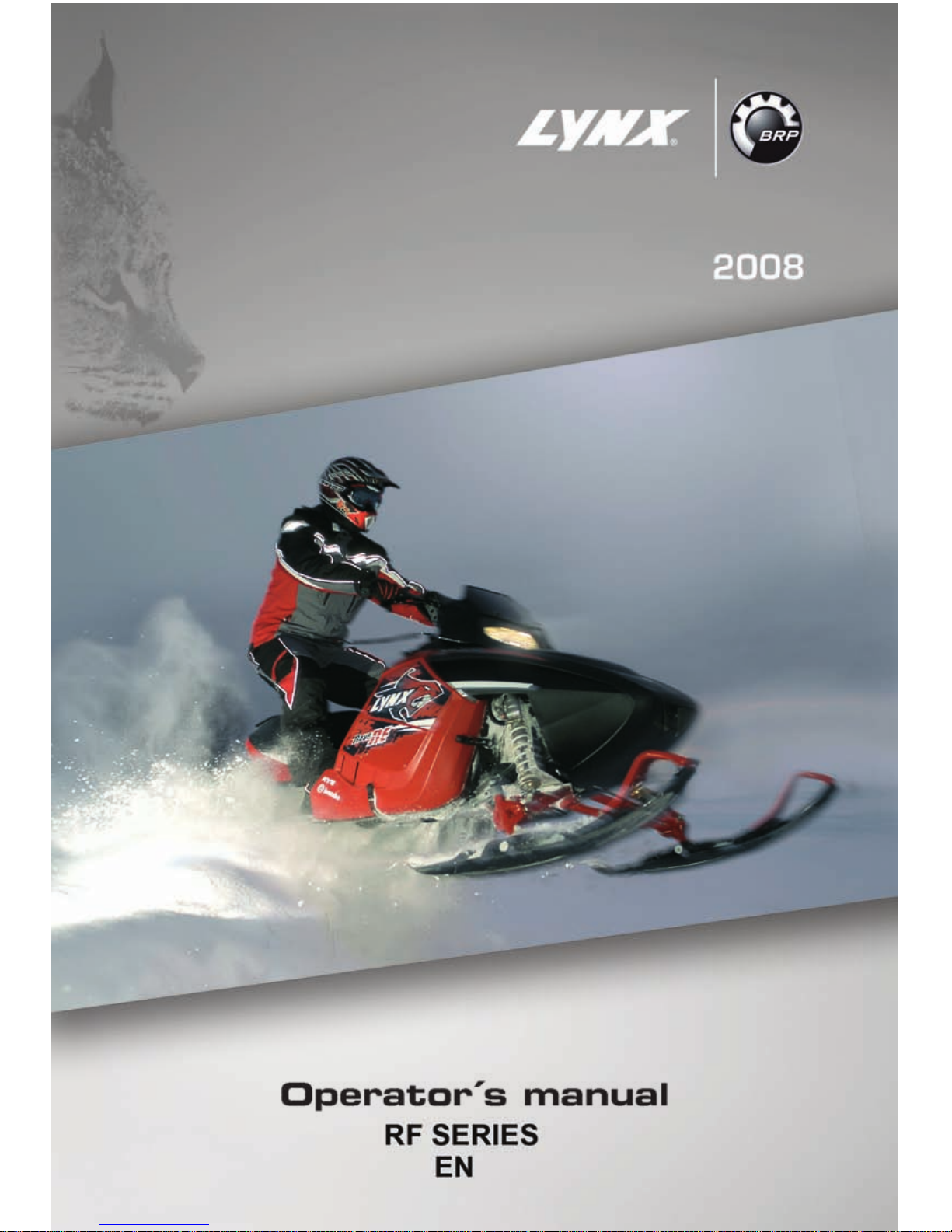
Sitting
Feet on the running boards, body midway back on seat is an ideal position
when operating the snowmobile over
familiar, smooth terrain. Knees and
hips should remain flexible to absorb
shocks.
____________
SAFETY INFORMATION
___________
15
Page 18
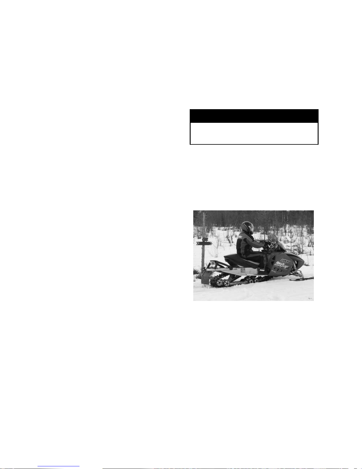
Posting
A semi-sitting position with the body
off the seat and the feet under the
body in a sort of squatting posture,
thus allowing the legs to absorb the
shocks when traveling over uneven
terrain. Avoid abru pt stops.
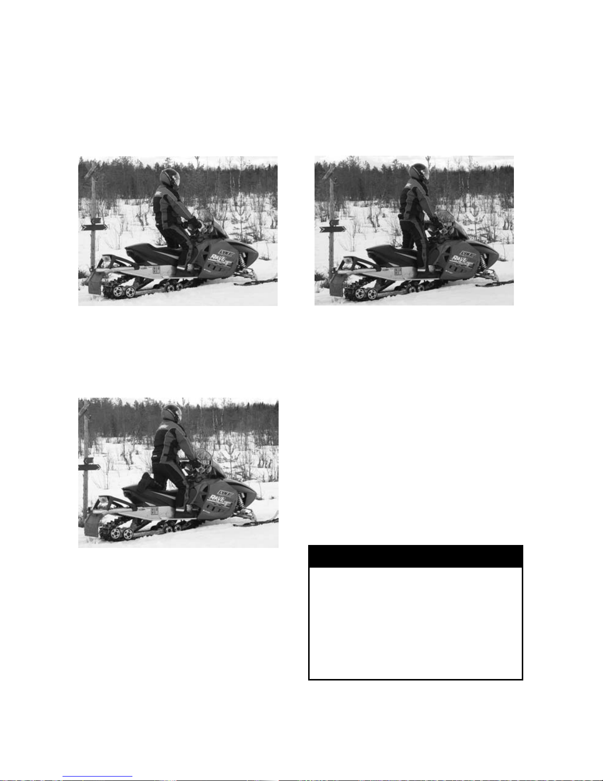
Kneeling
This position is achieved by placing
one foot firmly on the running board
and the opposite knee on the seat.
Avoid abrupt stops.
Standing
Place both feet o n the running boards.
Knees should be flexed to absorb the
shock from surface bumps. This is
an effective position to see better and
to shift weight as conditions dictate.
Avoid abrupt stop.
Carrying a Passenger
Certain snowmobiles are designed for
an operator only, others can allow one
passenger only, and others can allow
up to two passengers. Refer to the
indications on the vehicles to know if
any particular snowmobile can accommodate passengers or not, and if so,
how many. Always respect those indications. Overloading is dangerous because snowmobiles are not designed
for it.
Even when passengers are allowed,
you must make sure that the persons
who would like to become passengers
are p hysically fit for snowmobiling.
WARNING
Anypassengermustbeableto
firmly lay his feet on the footrests
andkeephishandsonthegrab
handles or seat strap at all times
when seated. Respecting those
physical criteria is important to
ensure that the passenger is stable
and to reduce the risks of ejection.
16
___________
SAFETY INFORMATION
___________
Page 19

On snowmobiles allowing two passengers, if you have an adult and a
child for passenger, BRP recommends
that the child sits in the center location. This a llows an adult sitting in the
rear seat to keep a visual contact with
the child and h old him if necessary.
In addition, the child is best protected
against the wind and cold temperature
if seated in the center lo catio n.
Each op e ra tor has a responsibility to
ensure the safety of his passengers
and should inform them of snowmobiling basics.
WARNING
– Passengers must only sit on
designated passenger seats.
Never allow anyone to sit between the handlebar and the
operator.
– Each passenger seat must have
a strap or grab handles and
meet SSCC standards.
– Passengers and operators must
always wear DO T approved helmets and warm clothing appropriate for snowmobiling. Make
sure that no skin is exposed.
– O nce underway, if a passenger
feels uncomfortable or insecure
for any reason, he must not
wait, and tell the driver to slowdown or stop.
Riding with passen gers on board is
different than riding alone. The operator has the benefit of knowing what
will be the next maneuver and is able
to prepare himself accordingly. The
operator also benefits from the support of his grip on the handlebar. In
contrast, the passengers have to rely on the operator’s carefu l and safe
operation of the vehicle. In addition,
“body english” is limited with passengers, and the operator can sometimes
see more of the trail ahead than the
passengers. Therefore, smooth starting and stopping are required with
passengers, and the operator must
slow down. The operator must also
warn passengers of side hills, bumps,
branches, etc. An unforeseen bump
can leave you passenger-less . Remind your passe n ge r s to lean into
the turn with you, without causing
the vehicle to topple. Be extremely
careful, go more slowly and check the
passengers frequently.
WARNING
When riding with a passenger:
– Braking ability and steering
control are reduced. Decrease
speed and allow extra space to
maneuver.
– Adjust suspension according to
weight.
For c omplete information on how
to adjust the suspension, please refer to the section of this Operator’s
Guide entitled SUSPENSION ADJUST-
MENTS under OPERATING INSTRUCTIONS and to the relevant label on the
belt guard.
Use extra caution and go even more
slowly with young passengers. Check
frequently to make certain the child
has a firm grip and is properly positioned with his feet on the running
boards.
____________
SAFETY INFORMATION
___________
17
Page 20

Terrain/Riding Variations
Groomed Trail
On a maintained trail, sitting is the
most preferred riding position. Do not
race and, above all, keep to the right
hand side of the trail. Be prepared
for the unexpected. Observe all trail
signs. Do not zigzag from one side of
the trail to the other.
Ungroomed Trail
Unless there has been a fresh snowfall you can expect “washboard” and
snowdrift conditions. Taken at excessive speeds, such conditions can be
physically harmful. Slow down. Hold
on the handlebar and assume a posting position. Feet should be under the
body assuming a crouched position to
absorb any jarring effect. On longer
stretches of “washboard” trails, the
kneeling position of one knee on the
seat can be adopte d. This provides
a certain amount of comfort, while at
thesametimekeepsthebodyloose
and capable of vehicle control. Beware of hidden rocks or tree stumps
partially hidden by a recent snowfall.
Deep Snow
In deep “powder” snow, your vehicle
could begin to “bog” down. If this occurs,turninaswideanarcaspossible and look for a firmer base. If you
do get “bogged”, and it happens to
everyone, do not spin your track as
this makes the vehicle sink deeper. Instead, turn the engine off, get off and
move the back of the vehicle onto new
snow. Then tramp a clear path ahead
of the vehicle. A few feet will generally suffice. Restart the engine. Assume the standing position and rock
the vehicle gently as you steadily an d
slowly apply the throttle. Depending
on whether the front or rear end of
the vehicle is sinking, your feet should
be placed on the opposing end of the
running boards. Never place foreign
material beneath the track for support.
Do not allow anyone to stand in front
of, or to the rear of, the snowmobile
with the engine running. Stay away
from the track. Personal injury will result if conta c t is made with th e revolving track.
18
___________
SAFETY INFORMATION
___________
Page 21

Frozen Water
Traveling frozen lakes and rivers can
be fatal. Avoid w aterwa ys. If you
are in an un fam iliar are a, ask the local authorities or residents about the
ice condition, inlets, outlets, springs,
fast moving currents or other hazards. Never attempt to operate your
snowmobile on ice that may be too
weak to support you and the vehicle.
Operating a snowmobile on ice or icy
surfaces can be very dangerous if you
do not observe certain precautions.
The very nature of ice is foreign to
good control of a snowmobile or any
vehicle. Traction for starting, turning
or stopping is much less than that
on snow. Thus, these distances can
be multiplied manyfold. Steering is
minimal, and uncontrolled spins are
an ever pre s e nt dange r. When op erating on ice, drive slow ly with caution.
Allow yourself plenty of room for
stopping and turning. This is especially true at night.
Hard Packed Snow
Don't underestimate hard packed
snow. It can be difficult to negotiate
as both skis and track do not have as
much traction. Best advice is to slow
down and avoid rapid acceleration,
turning or braking.
Uphill
There are two types of hills you can encounter — the open hill on which there
are few trees, cliffs or other obstacles,
and a hill that can only be climbed directly. On an open hill, the approac h
is to climb it by side hilling or slaloming. Approach at an angle. Adopt a
kneeling position. Keep your weight
on the uphill side at all times. Maintain a steady, safe speed. Continue
as far as you can in this direction, then
switch to an opposite hill angle and riding position.
A direct climb could present problems.
Choose the standing position, accelerate before you start the climb and
then reduce throttle pressure to prevent track slippage.
In either case, vehicle speed should
be as fast as the incline demands.
Always slow down as you reach the
crest. If you cannot proceed further,
don't spin your track. Turn the engine off, free the skis by pulling them
out and downhill, place the rear of the
snowmobile uphill restart the engine
and ease it out with slow even throttle
pressure. Position yourself to avoid
tipping over, then descend.
Downhill
Downhill driving requires that you
have full control of your vehicle at all
times. On s te e pe r hills, keep your
center of gravity low and both hands
on the handlebar. Maintain slight
throttle pressure and allow the machine to run downhill with the engine
operating. If a higher than safe speed
is reached, slow down by braking but
apply the brake w ith frequent light
pressure. Never jam the brake and
lock the track.
Side Hill
When crossing a side hill or traversing up or downhill, certain procedures
must be followed. All riders should
lean towards the slope as required
for stability. The preferred operating
positions are the kneeling position,
with the knee of the down hill leg
on the seat and the foot of the uphill leg on the running board, or the
posting position. Be prepared to shift
your weight quickly as needed. Side
hills and steep slopes are not recommended for a beginner or a novice
snowmobiler.
____________
SAFETY INFORMATION
___________
19
Page 22

Slush
Slush should be avoided at all times.
Always check for slush before starting across any lake or river. If dark
spots appear in your tracks, get off the
ice immediately. Ice and water can be
thrown rearward into the path of a following snowmobile. Getting a vehicle
out of a slush area is strenuous and in
some cases, impossible.
Fog or Whiteouts
On land or water, fog or visibilitylimiting snow can form. If you have
to proceed into the fog or heavy snow,
do so slowly with your lights on and
watch intently for hazards. If you are
not sure of your way, do not proceed.
Keep a safe distance behind other
snowmobilers to impr ove visibility
and reaction time.
Unfamiliar Territory
Whenever you enter an area that is
new to you, drive with extreme caution. Go slow enough to recognize
potential h azards such as fences or
fence posts, brooks crossing your
path, rocks, sudden dips, guy wires
and countless other obstacles whic h
could result in a termination of your
snowmobile ride. Even when following existing tracks, be cautious.
Travel at a speed so you can see what
is around the next bend or over the
top of the hill.
Bright Sunshine
Bright sunny days c an considerably reduce your vision. The glare from sun
and snow may blind you to the extent that you cannot easily distinguish
ravines, ditches or other obstacles.
Goggles with colored lenses should
always be worn under these conditions.
Unseen Obstruction
There may be obstructions hidden
beneath the snow. Driving off established trails and in the woods requires
reducedspeedandincreasedvigilance. Driving too fast in an area can
make even minor obstacles very hazardous. Even hitting a small rock or
stump could throw your snowmobile out of control and cause injury to
its riders. Stay on established trails
to reduce your exposure to hazards.
Be safe, slow down and enjoy the
scenery.
Hidden W ires
Always be on the lookout for hidden
wires, especially in areas that may
have been farmed at one time or another. Too many accidents have been
caused by running into wires in the
fields, guy wires next to poles and
roads, and into chains and wires used
as road closures. Slow speeds are a
must.
Obstacles and Jumping
Unplanned jumps of snowdrifts,
snowplow ridges, culverts or indistinguishable objects can be dangerous.
You can avoid them by wearing the
proper color lenses or face shields and
by operating at a lower speed.
Jumping a sno wmobile is an unsafe
and dangerous practice. However, if
the trail does suddenly drop away from
you, crouch (stand) towards the rear
ofthevehicleandkeeptheskisup
and straight ahead. Apply partial throttle and brace yourself for the impact.
Knees must be flexed to act as shock
absorbers.
20
___________
SAFETY INFORMATION
___________
Page 23
Tur nin g
Depending on terrain conditions, there
are two preferred ways to turn or corner a snowmobile. For most snow
surfaces, “body english” is the key to
turning. Leaning towards the inside of
the turn and positioning body weight
on the inside foot will create a “banking” condition beneath the track. By
adopting this position and positioning
yourself as far forward as poss ible,
weight will be transferred to the inside
ski.
On oc cas ion, you will find that the only way to turn the vehicle about in
deep snow is to pull the snowmobile
around. Do not over-exert yourself.
Get assistance. Remember to a lways
lift using your legs as opposed to your
back.
Road Crossing
In some cases, you will be approaching the road from a ditch or snowbank.
Choose a place where you know you
can climb without diffic ulty. Use the
standing position and proceed with only as much speed needed to crest the
bank. Stop completely at the top of
the bank and wait for all traffic to clear.
Judge the drop to the roadway. Cross
the road at a 90° angle. If you encounter another snowbank on the opposite side, position your feet near the
rear of the v eh icle. Remember, your
snowmobile is not designed to operate on bare pavement and steering on
this type of surface is more difficult.
Railroad Crossing
Never ride on railroad tra cks. It is illegal. Railroad tracks and railroad rightsof-way are private property. A snowmobile is no match for a train. When
crossing a railroad track, stop, look and
listen.
Night Rides
The amount of natural and artificial
light at a given time can effect your
ability to see or to be seen. Nighttime
snowmobiling is d elig htful. It can be
a unique experience if you acknowledge you r reduced visibility. Before
you start, m ake certain your lights
are clean and work properly. Drive
at speeds that will allow you to stop
in time when you see an unknown
or dangerous object ahead. Stay on
established trails and never operate in
unfamiliar territory. Avoid rivers and
lakes. Guy wires, barbed wire fences,
cabled road entrances and other objects such as tree limbs are difficult
to see at night. Neve r drive alo ne .
Always carry a flashlight. Keep away
from residential areas and respect the
right of others to sleep.
Safari Riding
Before starting out, designate a “trail
boss” to lead the party and a nother
person to follow-up at the end of the
party. Ensure that all members of the
party are aware of the proposed route
and destination. Make certain that
you are carrying all necessary tools
and equipment and that you have
sufficient fuel to complete the trip.
Never overtake the trail boss or, for
that matter, any other snowmobile.
Use down-th e-line hand signals to indicate hazards or intent of direc tio n
change. Assist others whenever necessary.
____________
SAFETY INFORMATION
___________
21
Page 24

ItisalwaysIMPORTANTtokeepa
safe distance between each snowmobile. Always maintain a safe interval
and allow sufficient stopping distance.
Don't be a tailgater. Know the position
of the machine ahead.
Signals
If you intend to stop, raise either hand
straight above your head. A left turn is
indicated by extending your left hand
straight out in the proper direction.
For right turns, extend the left arm and
raise the hand to a vertical position so
it forms a right angle at the elbow. Every snowmobiler should relay any signal to the ones behind.
Trail Stops
Whenever possible, pull off the trail
when you stop. This will reduce the
hazard to other snowmobilers using
the trail.
Trails and Signs
Trail signs are used to control, direct
or regulate the use of snowmobiles on
trails. Become familiar with all signs
used in the area where you are snowmobiling.
Transporting and Towing
Follow transporting and towing instructions explained further in this
guide.
22
___________
SAFETY INFORMATION
___________
Page 25
TRACTION ENHANCING PRODUCTS
NOTE: This section is applicable to
snowmobiles equipped with a factory
installed pre-studded Ice Series track
or a track that as been approved by
BRP for studs installation.
Using more positive carbide ski r unners and traction enhancing products
(Ice Series tracks or approved studded tracks) on your snowmobile will
change its behavior, particu larly in
terms of manoeuvrability, acceleration, and braking.
Using traction enhancing products
gives a better grip on packed snow
and ice, but has no noticeable effect on soft snow. For this reason,
driving a snowmobile equipped with
traction enhancing products (Ice Series tra cks , approved studded tracks,
carbide ski runners) requires a certain
adaptation period. If your snowmobile
is equipped with traction enhancing
products, be sure to take plenty of
time to get used to the way it h an dle s
when turning, accelerating, and braking.
Also, always check local regulations
concerning the use of traction enhancing products on snowmobiles.
Always drive your snowmobile in a
responsible manner, respecting the
environment and other people’s property.
Manoeuvrability
Using traction enhancing products
makes the snowmobile grip the
ground better at the rear. The use
of carbide runners is therefore required to give the skis a better grip, so
that the front and rear of the snowmobile are in balance. While off-the-shelf
carbide s ki runners are adequate,
they don’t necessarily give you optimal control, since that depends on
your personal preferences, your riding
style, and how your suspension is set.
WARNING
If the front and rear of the snowmobile are out of balance due to an
incorrect combination o f trac tio n
enhancing products and runners,
the snowmobile may tend to oversteer or understeer, which could
lead to a loss of control.
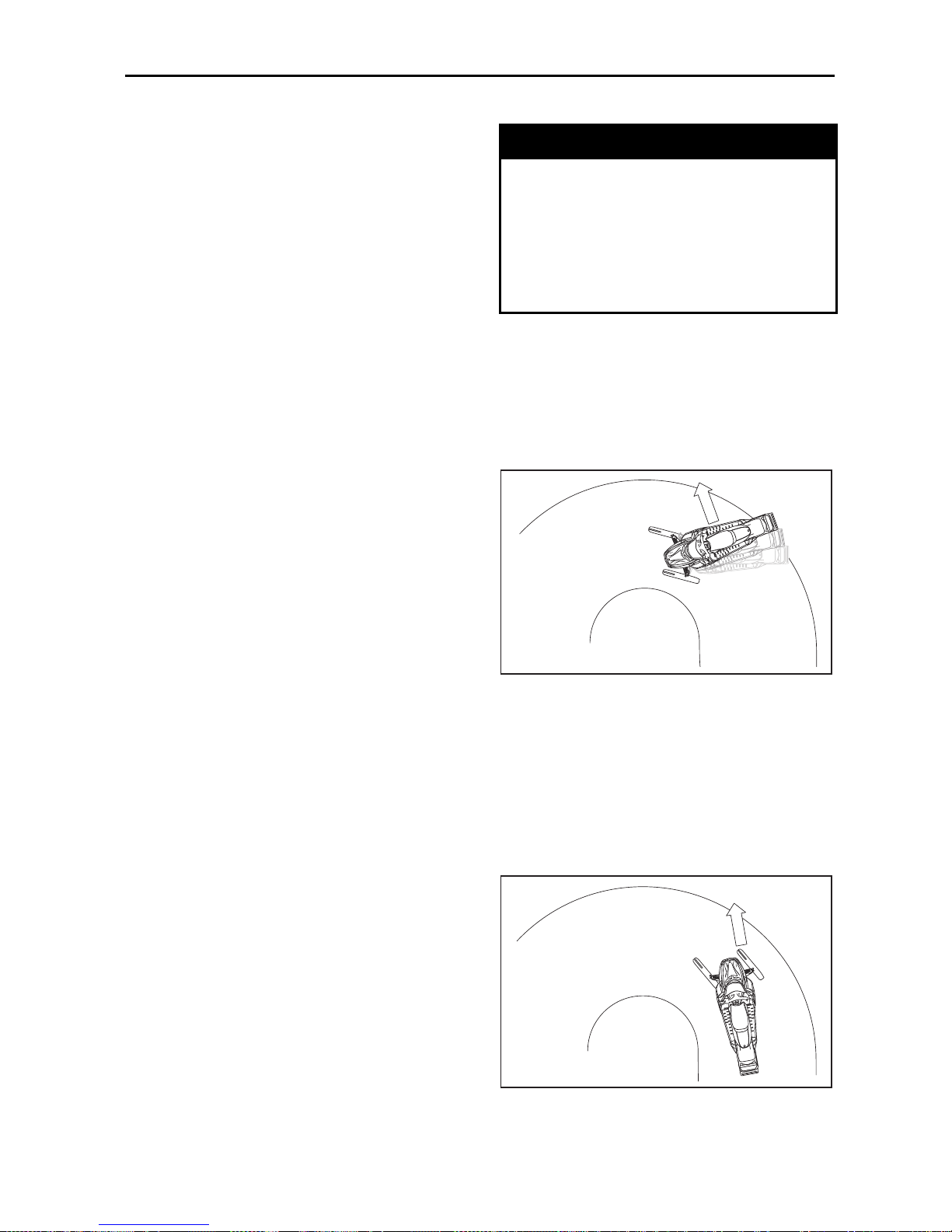
Oversteering
In certain conditions, using more positive carbide ski runners without traction enhancing products could make
the snowmobile prone to oversteering, see illustration.
A33A31A
OVERSTEERING
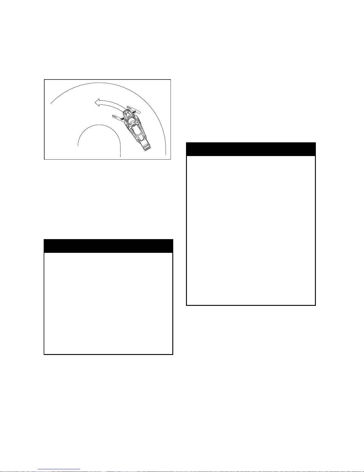
Understeering
In certain conditions, the use of traction enhancing products could make
the snowmobile prone to understeering if the skis are not equipped with
more positive carbide runners, see illustration.
A33A33A
UNDERSTEERING
____________
SAFETY INFORMATION
___________
23
Page 26
Controlled Driving
A balanced combination of carbide ski
runners and traction enh an cing products ensures adequate control and
better handling, see illustration.
A33A34A
CONTROLLED DRIVING
Acceleration
Using traction enhancing products will
allow your sled to accelerate better on
packed snow and ice but will have no
noticeable effect on soft snow. This
can cause sudden variations in traction
under certain conditions.
WARNING
To prevent surprises that could
lead to a loss of control of the
snowmobile, possibly resulting in
serious injury or death:
– Always go easy on the throttle.
– NEVER try to spin the track to
make the rear of the snowmo-
bile skid.
This could cause debris or ice to be
thrown violently backwards, possibly injuring others nearby or on
snowmobiles behind you.
Braking
As in the case of acceleration, using
traction enhancing products will give
you better braking capacity on packed
snow or ice but will have no noticeable effect on soft snow. Braking may
thus vary suddenly under certain conditions. Be sure to use restraint in
braking to keep from blocking the track
in order to avoid surprises that could
lead to a loss of control.
Important Safety R ules
WARNING
To prevent serious injury to individuals near the snowmobile:
– N EVER stand behind or near a
moving track.
– Always use a wide-base snow-
mobile stand with a rear deflector panel.
– W hen the track is raised off the
ground, only run it at the lowest
possible speed.
Centrifugal force could cause debris, damaged or loose studs,
pieces of torn track, or an entire severed track to be violently
thrown backwards out of the tunnel with tremendous force, possibly resulting in the loss of a leg or
other serious injury.
24
___________
SAFETY INFORMATION
___________
Page 27
Effects of Traction
Enhancing Products
ontheLifeofthe
Snowmobile
The use of traction enhancing products can increase the load and the
stress on certain snowmobile components, as well as the vibration level. This c an cause premature wear on
parts such as belts, brake linings, bearings, chain, chaincase sprocket, and
on approved studded tracks, shorten
track life. Always proceed with a visual inspection of your track before each
use. For more information, refer to
MAINTENANCE/REPLACEMENT section further in this guide.
Traction enhancing products can also
cause serious damage to your snowmobile if it is not equipped with the
tunnel protectors designed for your
particular model. Damage to the electrical wiring or perforation of the heat
exchangers are potential hazards, that
could cause the engine to overheat
and be severely damaged.
WARNING
If tunnel protectors are excessively
worn or not installed, the gas tank
could be punctured, causing a fire.
CAUTION: Ask your dealer for the
appropriate tunnel protectors model and kit number required for your
snowmobile.
NOTE: Consult the BRP limited war-
ranty to find out what w arra nty limitations are related to the use of studs.
Installation of Studs on
BRP Approved Tracks
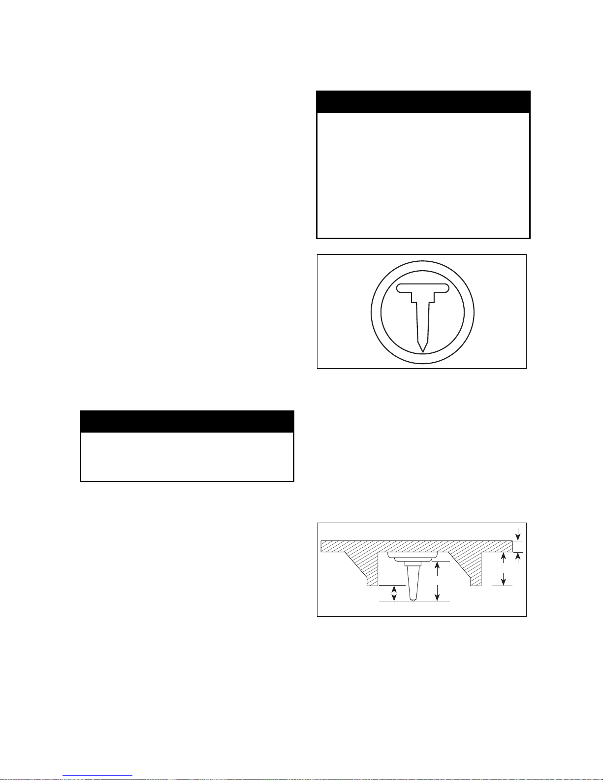
WARNING
Never stud a track that has not
been approved for studs. Approved tracks can be identified by
a stud symbol (see illustration)
molded into the track surface. Installing studs on an unapproved
track could increase the risk of the
track tearing or severing, possibly
resulting in serious injury or death.
A33A35A
APPROVED TRACKS CAN BE IDENTIFIED
BY THIS SYMBOL
To ensure safe and proper installation,
BRP recommends to have the studs
installed by your dealer.
– Use only studs, mounting plates,
andnutssoldbyBRP.
– Never use studs that exceed the
height of your snowmobile’s track
profile by more than 9.5 mm (3/8 in).
2
A33A32A
3
1
4
INSTALLATION OF STUDS
1. Stud size
2. Penetration range 6.4 to 9.5 mm
(1/4 to 3/8 in)
3. Track lug height
4. Track belt thickness
____________
SAFETY INFORMATION
___________
25
Page 28

WARNING
– Studs should only be installed in
the locations indicated by molded bulges in the track surface.
– N ever stud a track with a profile
of 35 mm (1.375 in) or more.
– The number of studs installed
must always perfectly match the
pattern of molded bulges in the
track.
– Always consult the traction
product manufacturer’s installation instructions and recommendations before having your
dealer install studs and runners.
It is very important to f ollow
the torque specifications for the
stud bolts.
INSTALLING AN INCORRECT
NUMBER OF STUDS OR AN IMPROPER INSTALLATION CAN INCREASE THE RISK OF THE TRACK
TEARING OR SEVERING, POSSIBLY RESULTING IN SERIOUS
INJURY OR DEATH.
Maintenance/Replacement
PROCEED WITH A VISUAL INSPECTION OF YOUR TRACK BEFORE
EACH USE.
Look for any d efects, such as:
– perforations in the track
– tears in the track (p articularly
around traction holes on studded
tracks)
– lugs that are broken or torn off, ex-
posing portions of rods
– delamination of the rubber
– broken rods
– broken studs (studded tracks)
– bent studs (studded tracks)
– missing studs
– studs that are torn off the track
– missing track guide(s).
On Ice Series pre-studded tracks, broken or missing studs can not be replaced.
On approved studded tracks, replace
broken or damaged studs immediately. If your track shows signs of deterioration, it must be replaced immediately. When in doubt, ask your dealer.
Always proceed with a visual inspection of your track before each use.
WARNING
Riding with a damaged track or
studs could lead to loss of control,
resulting in a risk of serious injury
or death.
26
___________
SAFETY INFORMATION
___________
Page 29
SAFETY LABELING
Safety standards for snowmobiles
have been adopted by the Snowmobile Safety and Certification Committee (SSCC) of which BRP is a proud
participating member. Assurance that
your snowmobile meets these standards is easily checked by locating the
Certification Label on a right vertical
portion of the vehicle.
This label shows that an independent
testing laboratory has verified compliance with the SSCC safety standards.
CE MODÈLE A ÉTÉ ÉVALUÉ
PAR UN LABORATOIRE
D'ESSAIS INDÉPENDANT
ET SATISFAIT TOUTES LES
NORMES DE SÉCURITÉ DU
SSCC EN VIGUEUR À LA
DATE DE FABRICATION.
PARRAINÉ PAR LE COMITÉ DE
SÉCURITÉ DE CERTIFICATION
DE LA MOTONEIGE, INC.
THIS MODEL HAS BEEN
EVALUATED BY AN INDEPENDENT TESTING LABORATORY AND IT MEETS ALL
SSCC SAFETY STANDARDS
IN EFFECT ON THE DATE OF
ITS MANUFACTURE.
SPONSORED BY THE SNOWMOBILE SAFETY AND CERTIFICATION COMMITTEE, INC.
PRINTED IN U.S.A.
CERTIFIED
CERTIFIÉ
A00A1MA
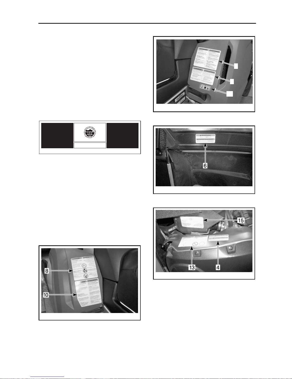
Other important labels on the vehicle
are WARNING or CAUTION labels relating to safety, maintenance and/or
snowmobile operation. Ensure all
such labeling is retained on the vehicle and its content is followed by
vehicle operator and passenger.
If missing or damaged, the decals can
be replaced. See an authorized LYNX
dealer.
Please read the following in stru ction s
carefully before operating this snowmobile.
mmo2006-004-004_a
LH SIDE PANEL
AVERTISSEMENT
WARNING
1
9
14
mmo2006-004-005_a
RH SIDE PANEL
mmo2006-004-022_a
INSIDE RH SIDE PANEL
mmo2006-004-021_a
PULLEY GUARD — FAN-COOLED
____________
SAFETY INFORMATION
___________
27
Page 30
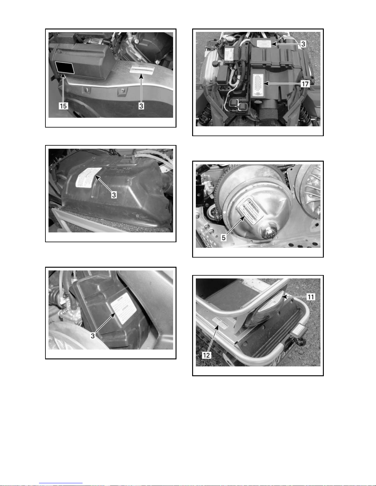
mmo2007-003-031_a
PULLEY GUARD — LIQUID-COOLED
mmo2006-004-025_a
AIR INTAKE SILENCER (BODY SIDE) —
FAN-COO L E D
mmo2006-004-024_a
AIR INTAKE SILENCER (ENGINE SIDE) —
FAN-COO L E D
mmo2007-003-032_a
AIR INTAKE SILENCER (ENGINE SIDE) —
LIQUID-COOLED
mmo2006-004-023_a
DRIVE PULLEY — FAN-COOLED
mmo2007-003-033_a
REAR CARGO AREA — (2-UP)
28
___________
SAFETY INFORMATION
___________
Page 31

2
mmo2006-004-028_a
EUROPEAN MODELS
Instruction 1
A33A2CA
Instruction 2
mmo2007-003-034_aen
ENGLISH LABEL
mmo2007-003-034_afr
FRENCH LABEL
Instruction 3
A01A2EA
Instruction 4
Ce garde-courroie doit TOUJOURS être en place lorsque le
moteur fonctionne. Attention aux pièces en rotation _ elles
peuvent vous blesser ou capter vos vêtements.
This guard must ALWAYS be in place when engine is running.
Beware of rotating parts _ they could cause injuries or
catch your clothing.
WARNING
AVERTISSEMENT
516 002 670
A33A2FA
Instruction 5
mmo2006-003-006_a
Instruction 6
Attention aux pièces CHAUDES!
Beware of HOT parts!
516002664
A33A2GA
____________
SAFETY INFORMATION
___________
29
Page 32

Instruction 8
mmo2006-004-002
Instruction 9
A33A2KA
Instruction 10
mmo2006-004-003
Instruction 11
A33A2NA
Instruction 12
NEVER SIT IN CARGO AREA.
Exceeding maximum cargo load
may affect steering
control and braking ability.
MAXIMUM cargo load :
XX Kg /XX Lbs.
NE JAMAIS S'ASSEOIR À LA PLACE DU CARGO.
Excéder le poids maximal du cargo peut
affecter le contrôle de la
direction et la capacité de freinage.
Charge MAXIMALE cargo :
XX Kg / XX Lbs.
mmo2007-002-002
Instruction 13
A33A2PA
FAN-COO L E D MODELS
Instruction 14
AVERTISSEMENT
WARNING
mmo2006-003-007_A
EUROPEAN MODELS
30
___________
SAFETY INFORMATION
___________
Page 33

Instruction 17
This is not a storage compartment.
Do not use this space for storage purpose.
Objects put in this space can limit steering and
can cause an accident ending in injury or death.
Ceci n'est pas un espace de rangement.
Ne pas insérer d'objet dans le compartiment
avant du véhicule, car cette action peut
occasionner un blocage de la conduite pouvant
entraîner de graves blessures ou la mort.
mmo2007-003-036
Hang Tag
704901107
vmo2006-005-009_en
____________
SAFETY INFORMATION
___________
31
Page 34

32
___________
SAFETY INFORMATION
___________
Page 35

ENVIRONMENT
INFORMATION
_____________________
33
Page 36

GENERAL
Wildlife compliments your snowmobiling day. Snowmobile tracks provide
firm ground over which animals can
travel from area to area. Do not violate this privilege by chasing or harassing wildlife. Fatigue and exhaustion
can lead to animal's death. Avoid areas posted for the protection or feeding of wildlife.
If you happen to be fortunate enough
to see an animal, stop your snowmobile and observe quietly.
The guidelines that we support are
not designed to limit your snowmobiling f u n, but to preserve the beautiful freedom that you can experience
only on a snowmobile! These guidelines will keep s nowmobilers healthy,
happy and able to introduce others to
what th ey know and enjoy about their
favorite winter pastime. So, the next
time you hit the trails on a cool, crisp
and clear winter day, we ask you to remember that you are paving the way
for the future of our sport. Help us
lead it down the right path! From all
of us at BRP, thank you f or doing your
share.
There is nothing more exhilarating
than snowmobiling. Venturing onto
snowmobile trails th at criss-cross the
wild areas is an e xciting and healthy
winter sport. However, as the number of people using these recreational
parks increases, so does the potential for damage to the environment.
Abuse of land, facilities and resources
inevitably leads to restrictions and clo sures of both private and public land.
In essence, the greatest threat to our
sport, is all around us. Which leaves
us with one logical choice. When we
snowmobile, we must always rid e responsibly.
The vast majority respect the law and
the environment. Each of us must set
an example for those who are new to
the sport, young and old alike.
It is in every one's best interest to
tread ligh tly into our recreational areas.
Because, in the long run, to protect the
sportwemustpreserve the environment.
Recognizing the importance of this issueandtheneedforsnowmobilersto
do their share in preserving areas that
make it possible to enjoy our sport,
BRP has developed the “Light Treading Is Smart Sledding” campaign for
snowmobilers.
Light Treading refers to more than the
thread of our tracks. It's a statement
of concern, respect and willingne ss to
take the lead and take action. It applies to the environment in general, its
proper care and maintenance, its natural inhabitants and all enthusiasts and
the public at large w ho enjoy the great
outdoors. With this theme, we invite
all snowmobilers to remember that respecting the environment is not only
critical to the future of ou r industry but
to future generations.
Light Treading in no way suggests you
should curb your appetite for snowmobiling fun! It simply means tread with
respect!
34
______________________
Page 37

JUST WHAT IS LIGHT TREADING?
The fundamental objective of Light
Treading is one of respect for where
and how you ride a snowmobile.
You're a light treader when you follow
the principles below.
Become informed. Obtain maps,
regulations and other information
from the Forest Service or from other
public land agencies. Learn the rules
and follow them and that goes for
speed limits, too!
Avoid running over young trees,
shrubs, and grasses and don't cut
wood. On flatlands or areas where
trail riding is popular, it's important to
ride only where authorized. Remember, there is a link between protecting
your environment and your own safety.
Respect wildlife andbeparticularly
sensitive of animals that are rearing
young or suffering from food shortage. Stress can sap scarce energy reserves. Refrain from riding in areas
where only animals are intended to
tread!
Obey gate closures and regulatory
signs and remember, light treaders
don't litter!
Stay out of wilderness areas. They're
closed to all v eh icle s. Know where
the boundaries are.
Obtain permission to travel across
private land. Respect the rights of
landowners and other people's privacy. Remember, snowmobile technology has lowered the noise factor
considerably, but you still shouldn't
rev your engines where quiet “is the
order of the day”.
_____________________
35
Page 38

WHY IS LIGHT TREADING SMART
Snowmobilers know all too well the
efforts that have been made throughout the sport's history to enjoy access
to areas where people can snowmobile safely and responsibly. This effort
continues today, as strong as ever.
Respectingtheareaswhereweride...
wherever they may be... is the only way to ensure their future enjoyment. That's one major rea son why
we know you'll a gree that Light Treading Is Smart Sledding! And there are
more.
Enjoying the opportunity to see winter
and all its natural majestic wonders,
is an experience cherished by snowmobilers. Light Treading will preserve
this opportunity and will make it possible for us to expose others to the
beauty of winter and the unique thrill
of our sport! Light Treading will help
our sport to grow!
Finally, Light Treading is the sign of a
smart snowmobiler. You don't have to
leave big tracks or careen through a virgin forest to show you can ride. So
whether you're driving a high performance LYNX snowmobile, show you
know what you're doing. Show you
know how to send snow flying and
make tra cks with a light touch!
36
______________________
Page 39

VEHICLE
INFORMATION
_____________________
37
Page 40

HOW TO IDENTIFY YOUR SNOWMOBILE
Vehicle Description Decal
Vehicle description decal is located on
right hand side of tunnel.
1.
TYPICAL
1. Vehicle description decal
VEHICLE DESCRIPTION DECAL
1. Manufacturer name
2. Manufacturing date
3. Vehicle identification number (VIN)
Serial Numbers
The main components of your snowmobile (engine and frame) are identified by different serial numbers. It
may sometimes become necessary
to locate these numbers for warranty
purposes or to trace your snowmobile
in the event of loss. These numbers
are required by the authorized LYNX
dealer to complete warranty claims
properly. No w arranty will be allowed
by BRP if the engine serial number or
vehicle identification number (VIN) is
removed or mutilated in any way. We
strongly recommend that you take
note of all the serial numbers on your
snowmobile and supply them to your
insurance company.
Vehicle Identification Number
(VIN) Location
VIN is scribed on vehicle description
decal. See above. It is also engraved
on tunnel near vehicle description decal.
Model Number Location
Model number is part of vehicle identification number (VIN).
VIN DESCRIPTION
Engine Serial Number Location
mmo2007-002-008_a
FAN-COOLED — 552 ENGINE TYPE
1. Engine serial number
38
______________________
Page 41

mmo2007-001-001_a
LIQUID-COOLED — V-810 ENGINE TYPE
1. Engine serial number
_____________________
39
Page 42

CONTROLS/INSTRUMENTS/EQUIPMENT
NOTE: Some controls/instruments/equipment do not apply or are optional on
some models. In these cases their reference numbers are deliberately mis sin g
in the illustrations.
TYPICAL — 2-UP MODEL
9
14
10
7
6
1 28 2
11
4
8
13
12-32
23
22
5
mmo2007-003-039_a
TYPICAL — CONSOLE
40
______________________
Page 43

1. Speedometer
2. Tachometer
3. Pilot lamps
4. Throttle lever
5. Brake lever
6. Parking brake lever
7. Multi-function switch
8. Handlebar
9. Ignition switch
10. Tether cut-out switch
11. Engine cut-out switch
12. Rewind starter handle
13. Choke lever
14. Fuel tank cap/gauge
15. Windshield
16. Hood and side panel latches
17. Fuses
18. Front bumper/grab handle
19. Seat latch
20. Storage compartment
21. Rear rack
22. Tool kit
23. Spark plug holder
24. Spare drive belt compartment
25. Hitch
26. Shields and guards
27. Track
28. Holding strap
29. Rear grab handles
30. Adjustable mirrors
31. Backrest
32. Gear shift lever
33. Seat strap
1) Speedometer
If so Equipped
Electronic speedometer that may
show speed in km/h or MPH.
Refer to UNIT SELECTION (MPH VS
KM/H) for changing units.
2
1
4
3
mmo2006-004-046_c
FAN-COO L E D MODELS
1. Reverse (RER) pilot lamp
2. High beam pilot lamp
3. Mode button
4. Multi-function display
1
3
2
6
5
4
mmo2006-004-046_b
LIQUID COOLED MODELS
1. High beam pilot lamp
2. Mode button
3. Multi-function display
4. Engine oil pressure pilot lamp
5. Low battery voltage pilot lamp
6. Engine overheat pilot lamp
Unit Selection (MPH vs km/h)
The speedometer is factory preset in
miles but it is possible to change it to
kilometer reading, refer to the following procedure or contact an authorized
LYN X d eal er.
NOTE: Speedometer, odometer and
trip meter will have their units (kilometer or miles) changed a ll together.
Stop engine.
OpenLHandRHsidepanels.
Unplug hood harness.
Open hood.
Underneath hood, look for:
– 1 circuit male connector housing
with BLACK/GREY wire
_____________________
41
Page 44

– 1 circuit female connector housing
with YELLOW /BLACK wire.
mmo2007-003-030_a
CONNECTOR LOCATION
Plug connectors together to change
units from miles to kilometers.
Unplug to return to miles reading.
Pilot Lamps
Reverse (RER) (fan-cooled)
This pilot lamp w ill light up when reverse is selected.
High Beam
This pilot lamp will light up when headlamp is on HIGH beam.
Liquid Cooled Models Only
Low Battery Voltage
This lamp will light up to indicate a
low battery voltage condition (on so
equipped models). See an autho-
rized LYNX dealer as soon as possible.
Engine Oil Pressure
This pilot lamp will light up when engine oil pressure is too low. Stop vehicle in a safe place then, check oil level
and replenis h as described in ENGINE
OIL LEVEL.
Restartengine,oilpilotlampmustturn
off after few seconds. If oil pilot lamp
still lights up, stop engine and have lubrication system inspected by an authorized LYNX dealer.
Engine Overheat
If this lamp blinks (1 short and 1 long
beep will also be heard), the engine
is overheating, reduce snowmobile
speed and run snowmobile in loose
snow or stop engine immediately and
allow engine to cool. Check cooling
system.
Mode Button
Depress mode button to change multifunction display.
Multi-function Display
NOTE: Each time engine is started,
display shows odometer.
DEPRESS MODE BUTTON TO
CHANGE DISPLAY
ODOMETER
TRIP METER
HOURMETER
Push and hold to
RESET
Return to
Odometer
Odometer
Odometer records the total distance
travelled and displays it either in miles
or kilometers.
Trip M et er (re set able)
Records distance travelled since it has
been reset. D istan ce travelled is displayed either in miles or kilometers.
Hourmeter (resetable)
Records engine running time in hours
and minutes since it has been reset.
Pushandholdmodebuttonfor2seconds to reset the hourmeter.
42
______________________
Page 45

Multi-Function Display Code
If your speedometer shows SCALE
in the multi-function display, it means
that the display selector button is
stuck in the down position or depressed when the electrical system
was activated.
2) Tachometer
If so Equipped
Direct-reading d ial indicates the number of thousand of revolutions per
minute (RPM) of the engine.
A33E0AA
TYPICAL — MULTIPLY THE READING
BY 1000
3) Pilot Lamps
Models without Speedometer
Reverse Pilot Lamp (Red)
This pilot lamp will light up
when reverse is selected.
High Beam Pilot Lamp (Blue)
Lights when headlamp is on
HIGH beam.
4) Throttle Lever
Located on the right hand side of handlebar and designed to be thumb activated. When squeezed, it increases the engine speed and engages the
transmission. When released, engine
speed returns automatically to idle.
WARNING
Test the throttle lever operation
each time before starting th e engine. The lever must return to its
original position once released.
Otherwise, do not start engine.
5) Brake Lever
Located on the left hand side of handlebar. When squeezed, the brake is
applied. When released, it automatically returns to its original position .
Braking effect is proportional to the
pressure applied on the lever and to
the type of terrain and its snow coverage.
6) Parking Brake Lever
Located on left hand side of handlebar.
Parking brake should be used whenever snowmobile is parked.
Whenever parking brake is applied and
engine is running, injection oil level/
parking brake pilot lamp lights up to
remind you that it is engaged.
WARNING
Make sure parking brake is fully
disengaged before operating the
snowmobile. When you ride the
vehicle, brake pads that are caused
to drag by a continuous pressure
onthelevermaycausedamageto
the brake system and cause loss of
braking capacity and/or fire.
_____________________
43
Page 46

To Engage Mechanism
Squeeze brake lever and maintain
while pushing locking lever with your
thumb. When brake lever is held at
halfway the parking brake should be
fully applied.
NOTE: Locking lever can be adjusted
in two different positions.
mmo2007-003-002_a
PARKING BRAKE
1. Locking lever
Step 1: Squeeze brake lever and maintain
Step 2: Push locking lever to 1
st
position
Step 3: Push locking lever to 2
nd
position
To Release Mechanism
Squeeze brake lever. Locking lever
will automatically return to its original position. Always release parking
brake before riding.
7) Multi-Function Switch
The contro ls located on this multifunction switch are:
mmo2007-003-003_a
1. Headlamp
2. Heated grips
3. Heated throttle lever
4. Reverse (RER)
Headlamp Dimmer Switch
Allows selection of headlamp beam.
Note that lights are automatically ON
whenever the engine is running.
Heated Grips
It is a three-position switch. Select
the desired position to keep your
hands at a comfortable temperature.
mmo2007-003-003_b
TYPICAL
1. Heatinggripswitch
2. Hot
3. Warm
4. Off
Heated Throttle Lever
It is a three-position switch. Select
the desired position to keep your
thumb at a comfortable temperature.
mmo2007-003-003_c
TYPICAL
1. Heated throttle lever switch
2. Hot
3. Warm
4. Off
44
______________________
Page 47

Reverse (RER)
Fan-Cooled Models
General
When the engine is running, depressing the RER button will command the
engine to reverse crankshaft rotation
as d riving the snowmobile in reverse
is achieved by changing the direction
of rotation of the engine, not by shifting the chaincase in reverse gear.
When depressing the RER button, the
electronic module will practically slow
down the engine RPM to a stop and
advance the ignition timing to cause
crankshaft rotation reversing.
Engine will automatically shift into forward when starting after stopping or
stalling.
Shifting procedure will take place only
when the engine is running.
If engine is running at a speed above
4300 RPM, the reverse function of the
RER button is cancelled.
It is recommended to warm up the engine to its normal operating temperature before shifting.
Shifting in Reverse
WARNING
Shifting to reverse mode on these
snowmobiles is done by depressing the RER button when the engine is running. Wait until the
reverse alarm sounds and the
RERpilotlampcomesoninthe
dash before operating throttle to
proceed in reverse. The reverse
speed of these snowmobiles is not
limited. Always proceed with caution as fast reverse could result
in loss of vehicle stabil ity. Come
to complete stop before depressing RER button. Always remain
seated and apply the brake before
shifting. Ensure the path behind
is clear of obstacles or bystanders
before proceeding.
With the snowmobile completely
stopped and engine running at idle,
press and release the RER button.
The reverse (RER
TM
) pilot lamp will
blink and a warning buzzer will sound
once every second with a half a second duration when the snowmobile is
engaged in reverse.
Apply throttle slowly and evenly. Allow drive pulley to engage then accelerate carefully.
Shifting in Forward
With the snowmobile completely
stopped and engine running at idle,
press and release the RER button.
Reverse (RER) pilot lam p and w arn in g
buzzer will stop.
Apply throttle slowly and evenly. Allow drive pulley to engage then accelerate carefully.
8) Handlebar
The handleba r controls the steering of
the snowmobile. As the handlebar is
rotated to right or left, the skis are
turned right or left to steer the snowmobile.
WARNING
Fast reverse while turning, could
result in loss of stability and control.
9) Ignition Switch
1 1
2
2
3
A23H04A
MANUAL START/ELECTRIC START MODELS
1. OFF
2. ON
3. START
_____________________
45
Page 48

2-Stroke Engine
Manual Starting
To start the engine, first turn the key to
ON position then, pull rewind starter
grip. To stop the engine, turn the key
to OFF position.
Electric Starting
To start engine, turn key to START position and hold until engine has started. See illustration above.
CAUTION: Do not use electric
starter for more than 10 seconds.
A rest period should be observed
between the cranking cycles to
let electric starter cool down. Using e lectric starter when engine
has started could damage electric
starter m echanism.
Release key as soon as the engine
starts. Key returns to ON position as
soon as it is released.
If engine does not start on first try,
turn key back to OFF position and wait
a few seconds before restarting. To
stop engine, turn key to OFF position.
NOTE: Engine may be manually started with rewind starter if necessary.
If starter does not operate, check starting system fuse condition. Refer to
FUSES.
4-Stroke Engine
Manual Starting
Thereisnomanualstartingonthese
models.
Electric Starting
To start engine, turn key to START position and hold until engine has started. See illustration above.
NOTE: If for any reason, the battery is
dead, engine cannot be started. Have
the battery recharged or replaced.
CAUTION: Do not use electric
starter for more than 10 seconds.
A rest period should be observed
between the cranking cycles to
let electric starter cool down. Using electric starter when engine
has started could damage electric
starter m echanism.
Release key as soon as the engine
starts. Key returns to ON position as
soon as it is released.
If engine does not start on first try,
turn key back to OFF position and wait
a few seconds before restarting. To
stop engine, turn key to OFF position.
If starter does not operate, check starting system fuse condition. Refer to
FUSES.
NOTE: When turning the key to OFF
position and removing the key, the vehicle electrical system will take a few
seconds to shut down.
10) Tether Cut-Out Switch
General
When the tether cord cap is removed,
its shuts the engine off preventing
snowmobile to runaway if the operator falls off the vehicle accidently.
WARNING
Always remove tether cord cap
and key when vehicle is not in
operation in order to prevent accidental engine starting, to avoid
unauthorized use by children or
others or theft.
Operation
Attach tether cord eyelet to clothing,
then snap tether cord cap over post
before starting engine.
46
______________________
Page 49

mmo2006-003-023_a
TYPICAL
1. Snap over post
2. Attach to eyelet
If emergency engine shut off is required, completely pull tether cord cap
from post.
11) Engine Cut-Out Switch
This p ush-pull type switch is located
on the right hand side of the handlebar.
To stop the engine in an emergency,
select OFF position and simultaneously apply the brake. To restart, button
must be at the ON pos itio n.
1
A17G1DA
2
TYPICAL
1. ON
2. OFF
All operators of the snowmobile
should familia rize themselves with
the f un ction of this dev ice by using
it several times on first outing and
whenever stopping the engine thereafter. This engine cut-out procedure
will become a reflex and w ill prepare
operators for emergency situations
requiring its use.
WARNING
If the switch has been used in an
emergency caused by a suspected malfunction, the source of the
malfunction should be determined
and corrected before restarting
engine. See an authorized LYNX
dealer for servicing.
12) Rewind Starter Handle
Fan-Cooled Models
Auto-rewind type located on right
hand side of snowmobile. To engage
mechanism, pull handle slowly until a
resistance is felt then pull vigorously.
Slowly release handle.
13) Choke Lever
This device features a 3-position lever
to facilitate cold start.
1
2
3
A06H1KA
1. OFF
2. Position 2
3. Position 3
Initial Cold Starting
NOTE: Do not operate the throttle
lever with the choke lever on.
_____________________
47
Page 50

Movethechokelevertoposition3and
start the engine. As soon as the engine starts move the lever to position
2. After a few seconds (10 seconds
maximum) move the choke lever to
OFF.
NOTE: In severe cold weather, colder
than - 20°C (- 4°F) you may need to flip
choke lever from OFF to position 1 a
couple of times once engine is started.
Warm Engine Starting
Start the engine without any choke.
If the engine will not start after two
pulls of the rope o r two 5 second a ttempts with the electric starter move
choke lever to position 2. Start the
engine without activating the throttle
lever. As soon as the engine starts
move the choke lever to OFF.
14) Fuel Tank Cap/Gauge
Unscrew to fill up tank then fully tighten.
Fuel tank cap features a mechanical
gauge.
WARNING
Always stop the engine before refueling. Fuel is flammable and explosive under certain conditions.
Always work in a we ll ventilated
area. Do not smoke or allow open
flames or sparks in the vicinity.
Open cap slowly. If a differential pressure condition is noticed
(whistling sound heard when loosening fuel tank cap) have vehicle
inspected and/or repaired before
further operation. Do not overfill or top off the fuel tank before
placing the vehicle in a warm area.
As temperature increases, fuel
expands and might overflow. Always wipe off any fuel spillage
from the vehicle. Periodically verify fuel system.
NOTE: Do not sit or lean on seat when
fuel tank cap is not properly installed.
15) Windshield
Windshield provides operator comfort,aswellasprotectionbydeflecting w ind and snow away from the
operator.
16) Hood and Side Panel
Latches
Side Panels Latch
To open a side panel, stretch and unhook the latch.
mmo2006-004-008_a
1. Latch
Push on top portion of side panel to
release it from hood.
Open side panel.
mmo2007-003-004_a
Step 1: Push to release
Step 2: Open side panel
To remove a side panel remove by
pulling up both locking devices from
hinge.
48
______________________
Page 51

1
A33H0EA
1. Locking device
Hood Latches
To open hood, open side panels first to
have access to hood latches, refer to
procedure above.
On RH side of vehicle, unplug hood
harness.
mmo2006-004-030_a
TYPICAL — FAN-COOLED MODELS
1. Hood harness
Stretch and unhook the hood latches.
mmo2006-004-031_a
TYPICAL ON BOTH SIDES
1. Latch
To remove hood, lift hood in a vertical
position then pull to remove.
mmo2006-004-032_a
HOOD REMOVAL
17) Fuses
Fuse Removal/Inspection
Check fuse condition and replace it if
necessary.
To remove fuse from holder, pull fuse
out. Check if filament is melted.
1
2
A15E0KA
1. Fuse
2. Check if melted
CAUTION: Do not use a higher rated fuse as this can cause severe
damage to electric components
and/or fire.
WARNING
If fuse has burnt out, source of
malfunction should be determined
and corrected before restarting.
See an authorized LYNX dealer for
servicing.
_____________________
49
Page 52

Description/Location
Fan-Cooled Models
MODEL FUSE DESCRIPTION LOCATION
Manual
start
20 A
Ground
protection
Behind RH
footrest
30 A
Charging system
Electric
start
20 A
Ground
protection
Top of battery
Ground Protection
CAUTION: This fuse should always
be disconnected before doing any
maintenance under the hood. This
is to prevent any unexpected electrical activation.
mmo2006-004-035_a
MANUAL START MODELS — BEHIND
RH FOOTREST
1. Ground protection fuse
mmo2006-004-033_b
ELECTRIC START MODELS
1. Ground protection fuse
Charging System
mmo2006-004-033_a
ELECTRIC START MODELS
1. Charging system fuse
Liquid Cooled Models
FUSE DESCRIPTION LOCATION
30 A Charging system On battery support
5 A Fuel injectors F1
10 A Fuel pump/ignition coil F2
5A
Engine Control Module
(ECM)/Crankshaft
Position Sensor (CPS)
F3
5A
Cluster/reverse alarm/
speed sensor/relay
F4
15 A
Heated grips and
thumb/power outlet/
visor outlet/taillight
F5
15 A Headlamp F6
Fuse box
Charging System
CAUTION: This fuse should always
be disconnected before doing any
maintenance under the hood. This
is to prevent any unexpected electrical activation.
50
______________________
Page 53

mmo2007-003-005_a
1. Charging system fuse
Fuse Box
Open side panels.
Open and remove front hood.
mmo2007-003-007_a
RH SIDE OF VEHICLE
1. Fuse box
To open fuse box push on cover tabs
and pull cover.
mmo2007-003-006_a
FUSE BOX COVER
Step 1: Push on tabs
Step 2: Pull cover
mmo2007-003-008_a
1. Fuses
2. Fuse remover/installer tool
3. Spare fuses
mmo2007-002-013
TYPICAL — REMOVE FUSE USING TOOL
18) Front Grab Handle/
Front Bumper
To be used whenever front of snowmobile requires manual lifting.
WARNING
Do not attempt to lift the vehicle
by hand alone. Use appropriate
lifting device or have assistance
to share lifting stress in order to
avoidriskofstraininjuries.
_____________________
51
Page 54

mmo2006-004-009_a
1. Front grab handle
CAUTION: Do not use skis to pull or
lift snowmobile.
CAUTION: Never use the front
bumper to lift the snowmobile for
maintenance purpose.
19) Storage Compartment
WARNING
Storage compartment must be
properly latched and must not
contain any heavy or breakable
objects.
To gain access to the storage compartment, unfasten buckles then pull on
seat panel.
mmo2007-003-009_a
STORAGE COMPARTMENT — 2-UP MODELS
1. Buckles
2. Seat panel
20) Rear Rack
WARNING
All objects in rear rack must be
properly latched. Do not carry
any breakable objects. Excessive
weight in rack may reduce steering ability.
CAUTION: Always readjust suspension according to the load. The capacity of this rack is limited, refer to
weight recommendation decal on
vehicle cargo rack. Ride at very low
speed w hen loaded. Avoid speed
over bumps.
21) Tool Kit
A tool kit containing tools for basic
maintenance is supplied with the ve hicle.
Tool bag is located in engine compartmentabovelefthandsidetoehold.
mmo2006-004-013_a
1. Tool kit
22) Spark Plug Holder
Fan-Cooled Models
To keep spare spark plugs dry and prevent shocks that might affect the adjustment or break them, a holder is
provided in engine compartment.
52
______________________
Page 55

mmo2006-004-036_a
SPARK PLUG HOLDER ON AIR INTAKE
SILENCER (BODY SIDE)
1. Spare spark plugs holder
NOTE: Spare spark plugs are not supplied with snowmobile.
NOTE: Check spare spark plug gap according to SPECIFICATIONS before in-
stallation.
23) Spare Drive Belt
Compartment
A spare drive belt can be stored in storage compartment. For more details,
refer to STORAGE COMPARTMENT.
NOTE: Spare drive belt is not supplied
with the snowmobile.
24) Hitch
The hitch can be used to pull most
equipment. Use a rigid tow bar.
25) Shields and Guards
WARNING
Never operate engine without belt
guard securely installed or, with
hood or access/side panels open
or removed.
Your sno wmobile is provided with a
number of shields and guards. Leave
these in place on your vehicle as they
are designed to keep clothing and
hands out of moving parts and away
from hot components. Never attempt
to make adjustments to any moving
part while the engine is running.
26) Track
Depending on the model of snowmobile that you own, your vehicle may
come with a track for which the manufacturer permits the installation of
studs, or a track for which the manufacturer forbids it.
Tracks approved for the installation of
studs have a stud sym bol (see illustration) molded into the track surface,
and tracks not appro ve d bear a forbidden stud symbol (see illustration).
Before proceeding with the installation of studs on tracks for which it is
allowed, you must first acquaint yourself with the safety instructions related to the studding of tracks, found
in the section entitled TRACTION EN-
HANCING PRODUCTS in the SAFETY
INFORMATION section at the begin-
ning o f this guide. This section also
provides other important information
that you must consider before having
studs installed on a track.
A00A8KA
12
TRACK SYMBOLS
1. Approved
2. NOT approved
For general instructions on maintenance of tracks, refer to the sections
TRACK CONDITION and TRACK TENSION AND ALIGNMENT in the MAINTENANCE section of this guide.
27) Holding Strap
Holding strap provides a grip for driver
when side-hilling.
_____________________
53
Page 56

WARNING
This strap is not for towing, lifting or other purpose than temporary use as a grab bar during sidehilling. Always keep at least one
hand on handlebar.
28) Rear Grab Handles
Rear grab handles provides a grip for
the passenger.
29) Adjustable Mirrors
Each mirror can be a djusted to suit
driver's preference.
WARNING
Adjust with vehicle at rest in a safe
place.
30) Backrest
Fixed backrest to increase passenger
comfort.
31) Gear Shift Lever
4-Stroke Models
These models are equipped with a
mechanical reverse controlled by a
2-position gear sh ift lever.
mmo2007-003-010_a
1. Forward
2. Reverse
Shifting Procedure
WARNING
The reverse speed of these snowmobiles is not limited. Always
proceed with caution as fast reverse could result in loss of vehicle stability and control. Come to
complete stop before selecting reverse gear. Wait until the reverse
alarm sounds before operating
throttle to proceed in reverse. Always remain seated and apply the
brake b efore shifting. Ensure the
path behind is clear of obstacles
or bystanders before proceeding.
With snowmobile completely stopped
and engine at idle, move lever to engage in desired gear.
Do not force lever. If unable to shift,
apply throttle to move snowmobile,
stop vehicle then, try again.
32) Seat Strap
Seat strap provides a grip for the passenger.
54
______________________
Page 57

RECOMMENDED FUEL AND OIL
Recommended Fuel
Use unleade d gasoline available from
most service stations or oxygenated
fuel containing a maximum total of
10% of ethanol or methanol or both.
The gasoline used must have the
following recommended minimum
octane number.
LOCATION
OCTANE
NUMBER
Inside North America
(87 ( RON +
MON)/2)
Outside North America 95E (RON)
CAUTION: Never experiment with
other fuels or fuel ratios. The use
of unrecommended fuel can result
in snowmobile performance deterioration and damage to critical parts
in the fuel system and engine components. Do not mistake oil reservoir cap for fuel tank cap. Oil reservoir cap i s identified OIL.
WARNING
Always stop the engine before refueling. Fuel is flammable and explosive under certain conditions.
Always work in a we ll ventilated
area. Do not smoke or allow open
flames or sparks in the vicinity.
Open cap slowly. If a differential pressure condition is noticed
(whistling sound heard when loosening fuel tank cap) have vehicle
inspected and/or repaired before
further operation. Do not overfill or top off the fuel tank before
placing the vehicle in a warm area.
As temperature increases, fuel
expands and might overflow. Always wipe off any fuel spillage
from the vehicle. Periodically verify fuel system.
Fuel System Antifreeze
When using oxygenated fuel, additional gas line antifreeze or water
absorbing additives are not required
and should be not used.
When using non-oxygenated fuel, we
highly recommend the use of isopropyl base gas line antifreeze in a
proportion of 150 mL (5 U.S. oz) of
gas line antifreeze added to 40 liters
(10-1/2 U.S. gal) of gas.
This precaution is in order to reduce
the risk of frost buildup in carburetor(s)
which may lead, in certain cases, to
high fuel consumption or severe damage to engine.
NOTE: Use only methy l hydrate free
gas line antifreeze.
Recommended Oil
2-Stroke Engine
CAUTION: Use only injection oil
that flows at - 40°C (- 40°F). Do not
mismatch oil reservoir c ap with
fuel tank cap. Oil reservoir cap is
identified OIL.
Oil is contained in the injection oil
reservoir.
Use only two-stroke engine injection
oil sold by authorized LYNX dealers.
OIL TYPE
XP-STMmineral i njection oil
(1)
or XP-S
Synthetic Blend 2–Stroke Injection or
XP-S Fully Synthetic 2–Stroke Injection oil
(1)
If XP-STMmineral injection oil is not
available, API TC high-quality low ash
two-stroke inje ction oil may be used.
XP-S
TM
mineral injection oil is a special
blend of basic oil and additives especially selected to ensure unequalled lubrication, engine cleanliness and minimum spark plug fouling.
_____________________
55
Page 58

CAUTION: Never use four-stroke
petroleum or synthetic motor oil
and never mix these with outboard motor oil. Do not use NMMA
TC-W, TC-W2 or TC-W3 outboard
two-stroke engine oils or ashless
two-stroke engine oils. Avoid mixing different brands of API TC oil as
resulting chemical reactions may
cause severe engine damage.
Always maintain a suffic ient amount
of recommended oil in the injection oil
reservoir.
CAUTION: Check level and refill every time you refuel. Do not mismatch oil reservoir cap with fuel
tank cap. Install cap that is identified OIL.
WARNING
Do not overfill. Reinstall cap and
fully tighten. W ipe off any oil
spills. Oil is highly flammable.
4-Stroke Engine
Use SAE 0W 40 synthetic-based oil
that meets or exceeds the requirements for API service classification
SM, SL or SJ. Always check the API
service label certificatio n on the oil
container, it must contain at least one
of the above standards.
NOTE: This is the only recommended
viscosity to ensure proper cold start
and optimum engine protection at high
RPM and temperature.
MODEL OIL TYPE
V-800
Series
XP-S
TM
0W 40
synthetic oil or an equivalent
56
______________________
Page 59

BREAK-IN PERIOD
Engine
CAUTION: A break-in period of
10 operating hours — 500 km
(300 miles) — is requ i re d before
running the snowmobile at full
throttle.
During break-in period, maximum
throttle should not exceed 3/4.
However, brief full acceleration and
speed variations contribute to a good
break-in.
CAUTION: Engine overheating,
continued wide open throttle runs
and prolonged cruising without
speed variations should be avoided, this can cause engine damage
during the break-in period.
Models Equipped with
2-Stroke Engines
To assure additional protection during
the initial engine break-in, 500 mL
(18 imp. oz) of recommended injection oil should be added to fuel for the
first full filling of fuel tank. Have spark
plugs cleaned after engine break-in.
Belt
A new drive belt requires a break-in period of 50 km (30 miles). Avoid strong
acceleration/deceleration, pulling a
load or high speed cruising.
10-Hour Inspection
NOTE: The 10-hour inspection is at the
expense of the snowmobile owner.
As with any precision piece of mechanical equipment, we suggest that
after the first 10 hours of operation or
500 km (300 m iles) , whichever comes
first, your snowmobile be checked by
an authorized LYNX dea ler. This inspection will also give you the opportunity to discuss the unanswered questions you may have encountered during the first hours of operation.
_____________________
57
Page 60

OPERAT ING INSTRUCTIONS
Pre-Operation Check
WARNING
The pre-operation check is very
important prior to operating the
vehicle. Always check the proper operation of critical controls,
safety features and mechanical
components before starting. If
not done as specified here, severe
injury or death might occur.
• Remove snow and ice from body including seat, footrests, controls and
instruments.
• Lights — The headlamp, the taillight and the brake light are standard equipment. Be sure lights are
clearofdirt,slushorsnowandare
in good working order or condition.
• Verify that track and idler wheels
are free to turn and not frozen.
WARNING
Alwaysuseawidebasesnowmobile mechanical stand to properly
support vehicle during any track
verification. Slowly accelerate engine in order to rotate track at
very low speed when it is not on
ground.
• A ctivate the brake control lever
and make sure the brake fully applies before the brake control lever
touches the handlebar grip. It must
fully return when released.
• C heck the parking device. Apply
parking brake and check if it operates properly.
• A ctivate the throttle control lever
several times to check that it operates easily and smoothly.
WARNING
Throttle lever must operate easily and smoothly. It must return to
idle position when released.
• Check operation of tether and
engine cutout switches, ignition
switch, headlamp switch (HI-LO),
taillight, brake light and pilot lamps.
• Check gear shift lever position
(4-stroke models only).
• Verify that skis and steering operate
freely. Check corresponding action
of skis versus handlebar.
• Check fuel and oil for levels and
leaks. Replenish as necessary and
see an authorized LYNX dealer in
case of any leaks.
• Verify that air filter(s) is free of
snow, if so equipped.
• A ll storage compartments must be
properly latched and they must not
contain any heavy or breakable objects. Hood must be also properly
latched.
WARNING
All adjustable features should be
positioned at optimal setting. Securely tighten all adjustment locks.
• Make certain your snowmobile is
pointed away from people or objects before you start it. No one is
to be standing in front of or in back
of the snowmobile.
• Be warmly dressed with clothing
designed for snowmobiling.
58
______________________
Page 61

PRE-OPERATION CHECK LIST
ITEM OPERATION
Body including seat, footrests,
lights, controls and instruments
Check that there is no snow or ice.
Track and idler wheels
Check for free movement.
Brake lever
Check proper action.
Parking device
Check proper action.
Throttle lever
Check proper action.
Switches and lights
Check proper action. Tether cord must be
attached to driver clothing eyelet.
Skis and steering
Check for free movement and proper action.
Fuel an d oil
Check for proper level and leaks.
Air filter
Check that there is no snow or ice.
Adjustable feature s
Check for optimal adjustment and securely
tightened adjustment locks.
Storage compartment
Check for proper latching and no heavy or
breakable objects.
Vehicle vicinity
Snowmobile must be pointed away from people
or objects. No one is to be standing in front of
or in back of the snowmobile.
Clothing
Be warmly dressed with clothing designed for
snowmobiling.
Engine Starting Procedure
(2-Stroke)
Procedure
• Recheck throttle control lever operation.
• Ensure that the tether cord cap is
in position and that the cord is attached to your clothing eyelet.
• E nsure that the engine cutout
switch is in the ON position.
• Turn ignition key to ON position.
• Activate the choke according to the
temperature as explained below.
Choke Application
Initial Cold Starting When
Temperature is Below - 10°C (+ 15°F)
NOTE: Do not operate the throttle
lever with the choke lever on.
Set the choke lever to position 3.
Start the engine using the manual or
electric starter (if so equipped).
After the engine is started, let engine
warm up at fast idle until engine speed
drops. Then, close off choke to ensure proper air-fuel mixture.
_____________________
59
Page 62

1
2
3
A06H1KA
1. OFF
2. Position 2
3. Position 3
Initial C old Startin g Whe n
Temperature is Above -10°C
(above + 15°F)
Set the choke lever to position 2.
Start the engine using the manual or
electric starter (if so equipped).
After the engine is started, close off
choke to ensure proper air-fuel mixture.
Warm Engine Starting
Start the engine without any choke using the manual or electric starter (if so
equipped).
If the engine will not start after two
pulls of the rope o r two 5 second a ttempts with the electric starter move
choke lever to position 2. Start the
engine without activating the throttle
lever. As soon as the engine starts
move the choke lever to OFF.
Procedure (cont'd)
Manual Starting
• Grab m anual starter handle, pull
handle slowly until a resistance is
felt, then hold handle firmly and pull
vigorously to start engine.
Electric Starting (if so equipped)
WARNING
Never depress throttle while starting engine.
CAUTION: Do not use electric
starter for more than 10 seconds.
A rest period should be observed
between the cranking cycles to
let electric starter cool down. Using electric starter when engine
has started could damage electric
starter m echanism.
• Turn key clockwise until starter engages.
• R elease key immediately when engine has started.
NOTE: If for any reason, the engine
cannot be cranked electrically, leave
ignition key to ON position and start
engine manually using the rewind
starter.
Engine Starting Procedure
(4-Stroke)
Procedure
• Recheck throttle control lever operation.
• Ensure that the tether cord cap is
in position and that the cord is attached to your clothing eyelet.
• E nsure that the engine cutout
switch is in the ON position.
• Turn ignition key to ON position.
NOTE: Engine will not start if the throttle lever is depressed.
CAUTION: Do not use electric
starter for more than 10 seconds.
A rest period should be observed
between the cranking cycles to
let electric starter cool down. Using electric starter when engine
has started could damage electric
starter m echanism.
• Turn key clockwise until starter engages.
• R elease key immediately when engine has started.
NOTE: If for any reason, the battery is
dead, engine cannot be started. Have
the battery recharged or replaced.
60
______________________
Page 63

Vehicle Warm-Up
Before every ride, vehicle has to be
warmed up as follows.
Snowmobile must be securely supported by the rear bumper using a
wide-base snowmobile mechanical
stand. Track must be 100 mm (4 in)
off the ground.
Attach tether cord to operator's clothing eyelet.
Start engine and allow it to warm up
two or three minutes at idle speed.
Release parking brake.
WARNING
Make sure wide-base snowmobile
mechanical stand is stable. Stay
clear of the front of vehicle and the
track. Do not use too much throttle
during warm-up or when track is
free-hanging.
Apply throttle until drive pulley engages. Let track rotate at low speed
for several turns. The lower the vehicle temperature is the longer vehicle
warm-up should be.
Shut-off the engine and remove the
wide-base snowmobile mechanical
stand.
Skis may be frozen on the ground.
Grab both skis one a t a time by their
loops and lift their front end slightly off
the ground.
After restarting engine, the vehicle can
be driven at low speed for the first 2 or
3 minutes of riding. After that, it may
be driven up to the legal speed limit as
per normal safety practices.
Shutting Off t he Engine
Release throttle lev er and wait until
engine has returned to idle speed.
Shut off the engine using either ignition switch, engine cut-out switch or
tether cut-out switch.
WARNING
Always remove tether cord cap
and key when vehicle is not in
operation in order to prevent accidental engine starting or to avoid
unauthorized use by children or
others or theft.
Post-Operation Care
Shut off the engine. Install rear of vehicle on a wide-base snowmobile mechanical stand.
Remove s now and ice from rear
suspension, track, front suspension,
steering mechanism and skis.
Always cover your snowmobile when
leaving it overnight or during extended
periods of inactivity. This will protect
it from free zin g as well as retain its
appearance.
Suspension Adjustments
Snowmobile handling and comfort depend upon suspension adjustments.
For factory recommended adjustments refer to decal on the belt guard.
It describes settings for optimum
comfortaccordingtoloadforyour
LYN X m ode l.
Choice of suspension adjustments
vary with carry ing load, driver's
weight, personal preference, riding
speed and f ield condition.
NOTE: Some adjustments may not apply to your snowmobile. Use special
keys in tool kit.
REAR SUSPENSION
MODELS TYPE
Adventure V800
SC
Ranger V-800
RCG
Ranger 550F
RCG
_____________________
61
Page 64

1.
2.
3.
TYPICAL — RCG-SUSPENSION
1. Center spring for steering behavior
2. Rear spring for comfort and ride height
3. Stopper strap for snowmobile weight
transfer
1
4
3
2
mmo2006-004-038_a
TYPICAL — SC-SUSPENSION
1. Rear springs adjustable cams fo r
comfort and ride height
2. Center spring for steering behavior
3. Stopper strap for snowmobile weight
transfer
4. Rear shock motion ratio — Damping
strength (not adjustable)
5.
6. Front springs for handling (not adjustable
on all models) (not shown)
Following are guidelines to fine-tune
suspension.
The best way to set up the suspension, is to start from factory set tings,
then customize each adjustment one
at a time. Adjustments 2 through 6
are interrelated. It may be necessary
to readjust center spring after adjusting front springs for instance. Test run
the snowmobile under the same conditions; trail, speed, snow, driver riding
position, etc. Change one adjustment
and retest. Proceed methodically until you are satisfied.
WARNING
Always remove tether cord cap before performing any maintenance
or adjustment, unless otherwise
specified. Vehicle must be parked
inasafeplace,awayfromthetrail.
Always lift the front of vehicle off
the ground with a suitable lifting
device before adjusting ski suspension. Lift the rear of vehicle
off the ground with a wide-base
snowmobile stand with a rear deflector panel before rear suspension adjustment.
WARNING
Do not att empt to lift the vehicle by
hand alone. Use appropriate lifting device to avoid risk of strain injuries. Always make sure the lifting dev ice is stable and secure before proceeding to adjust the suspension components.
CAUTION: Whenever adjusting
rear suspension, check track tension and adjust as necessary.
Slight suspension bottoming occurring
under the worst riding conditions indicatesagoodchoiceofspringpreload.
Rear Springs — Comfort
IMPORTANT: Make sure that all objects to be transported are in place in
storage compartment and rear rack.
• Grab rear bumper and lift until suspension is fully extended.
• From this point, rear of snowmobile
shouldcollapseby50to75mm(2
to 3 in) when driver and passenger
(if so applicable) take place. Measure at rear bumper as shown in
next photo.
62
______________________
Page 65

WARNING
Do not attempt to lift the vehicle
by hand alone. Use appropriate
lifting device or have assistance
to share lifting stress in order to
avoidriskofstraininjuries.
C
B
A
mmo2006-003-022_a
TYPICAL — PROPER ADJUSTMENT
A. Suspension fully extended
B. Suspension has collapsed with drive r,
passenger(s) and load added
C. Distance between dimension A and B, must
notexceed50to75mm(2to3in),seetable
REAR SPRINGS ADJUSTMENT
”C” CAUSE SOLUTION
50 to 75 mm
(2 to 3 in)
No adjustment required
More than
75 mm (3 in)
Adjusted
too soft
Increase
preload
Less than
50 mm (2 in)
Adjusted
too hard
Decrease
preload
Preload Adjustment
NOTE: Left and right adjustment cams
may be at different settings.
CAM
POSITIONS
SPRING PRELOAD
1
Minimum
2 Minimum/Intermediate
3 Intermediate/Maximum
4
Maximum
CAUTION: To increase preload, always turn the left side adjustment
cam in a clockwise direction, and
the right side cam in a counterclockwise direction.
A32F41A
RHLH
1 1
TYPICAL
1. Increase spring preload
1. Increase spring preload (RCG)
CAUTION: To decrease preload,
always turn the left side adjustment cam in a counterclockwise
direction, the right side cam in a
clockwise direction.
A30F04B
RHLH
1 1
TYPICAL
1. Decrease spring preload
_____________________
63
Page 66

1. Decrease spring preload (RCG)
Center Spring — Steering
Behavior
• Ride at moderate speed on a trail.
• If handlebar is felt too easy or too
hard to turn, adjust center spring
accordingly.
WARNING
Before proceeding with any suspension adjustment, remember:
– park in a safe place
– remove tether cord cap
– lift rear of vehicle off the ground
with a wide-base snowmobile
stand with a rear deflector panel
– make sure lifting device is stable
and secure.
CENTER SPRING ADJUSTMENT
HANDLEBAR
(steering
attitude)
PROBLEM SOLUTION
Easy to turn
(neutral)
No adjustment required
Harder to turn
(oversteering)
Adjusted
too soft
Increase
preload
Very easy
to turn
(understeering)
Adjusted
too hard
Decrease
preload
Preload Adjustment
A32F01A
1
TYPICAL
1. Use adjuster wrench provided in tool kit
to increase or decrease preload
Stopper Strap — Weight
Transfer
• R ide at low speed then fully accelerate.
• Notesteeringbehavior.
• Adjust stopper strap length accordingly.
WARNING
Before proceeding with any suspension adjustment, remember:
– park in a safe place
– remove tether cord cap
– lift rear of vehicle off the ground
with suitable lifting device
– make sure lifting device is stable
and secure.
CAUTION: Whenever stopper strap
length is changed, track tension
must be readjusted.
64
______________________
Page 67

STOPPER STRAP — WEIGHT TRANSFER
WEIGHT TRANSFER ADJUSTMENTS
Steering Track (skis) Problem Solution
Comfortable
Good weight
transfer (light
pressure)
No adjustment
required
Light
Too muc h
weight transfer
(lift off the
ground)
Strap too
long
Reduce
strap
length
Heavy
Not enough
weight
transfer (heavy
pressure)
Strap too
short
Increase
strap
length
Strap Adjustment
A03F0QB
1
TYPICAL
1. Increase or decrease strap length by
bolting to a different hole
Front Springs — Handling
NOTE: Front shock springs are adjustable on some models only.
• Ride at moderate speed and check
for proper handling.
• A djust front springs accordingly.
WARNING
Before proceeding with any suspension adjustment, remember:
– park in a safe place
– remove tether cord cap
– lift rear of vehicle off the ground
with a wide-base snowmobile
stand with a rear deflector panel
– make sure lifting device is stable
and secure.
WARNING
Always adjust both front springs to
same position.
FRONT SPRINGS ADJUSTMENT
HANDLING STEERING PROBLEM SOLUTION
Good Comfortable No adjustment required
Bad
Too easy
to turn
Adjusted
too soft
Increase spring
preload
Bad Hardtoturn
Adjusted
too hard
Decrease spring
preload
Preload Adjustment
A03F2IA
1
TYPICAL
1. Increase or decrease spring preload
CAUTION: Make sure that both
front springs are still pre loaded
whenfrontofvehicleisoffthe
ground.
_____________________
65
Page 68

SUSPENSION TROUBLESHOOTING CHART
PROBLEM CORRECTIVE MEASURES
Front suspension wandering
– Check ski alignment and camber angle a djustment.
SeeanauthorizedLYNXdealer.
– Reduce ski ground pressure.
• Increase center spring preload.
• Reduce rear spring preload.
Snowmobile seem s unstable
and seems to pivot around its
center
– Reduce rear suspension front arm pressure.
• Reduce center spring p reload.
• Increase rear spring preload.
Steering feels too heavy
– Reduce ski ground pressure.
• Increase center spring preload.
Rear of snowmobile seems
too stiff
– Reduce rear spring preload.
Rear of snowmobile seems
too so ft
– Increase rear spring preload.
Rear suspension front
shock absorber is frequently
bottoming
– Lengthen stopper strap.
– Increase center spring preload.
Track spins too much at start – Lengthen stopper strap.
– Move thicker part of coupling block
downward.
In Deep Snow
When operating the snowmobile in deep snow, it may be necessary to vary stopper strap length and/or riding position, to change the angle at which the track rides
on the snow. Operator's familiarity w ith the various adjustments as well as snow
conditions will dictate the most efficient combination.
66
______________________
Page 69

SPECIAL OPERATING INSTRUCTIONS
Riding at High Altitudes
or Sea Level
CAUTION: Failure to re-calibrate
may cause serious engine damage.
Those models are calibrated for SEA
LEVEL operation.
Operating above 600 m (2000 ft) requires parts and adjustments.
RefertoanauthorizedLYNXdealerfor
proper calibration modifications.
Riding in Cold Weather
All vehicles have been calibrated for
- 20°C (- 4 °F). They can be operated at
warmer winter temperatures without
problems.
CAUTION: Forcoldertemperatures
than - 20°C (- 4°F), carburetor(s)
must be recalibrated to avoid engine damage. Refer to an authorized LYNX dealer.
Refer also to RIDING AT HIGH ALTITUDES OR SEA LEVEL in previous
pages.
Emergency Starting
Fan-Cooled Models Only
The engine can be started with the
emergency starter rope supplied with
the tool kit.
Remove belt guard.
WARNING
Do not wind starting rope around
your hand. Hold rope by the handle only. Do not start the snowmobile by the drive pulley unless it is
atrueemergencysituation. Have
the snowmobile repaired as soon
as possible.
A07D0UA
Attach one end of emergency rope to
rewind handle.
NOTE: The spark plug socket can be
used as an emergency handle.
A17B01A
TYPICAL
Attach the other end of emergency
rope to the starter clip supplied in the
tool kit.
Hook up clip on drive pulley.
Wind the rope tightly around drive pul-
ley. When pulled, pulley must rotate
counterclockwise.
_____________________
67
Page 70

A03D25A
1
TYPICAL
1. Knot on this side
Pull the rope using a sharp, crisp pull
so the rop e comes free of th e driv e
pulley.
Start engine as per usual manual starting.
WARNING
When starting the snowmobile
in an emergency situation, using
drive pulley, do not reinstall the
belt guard and return slowly to
have snowmobile repaired.
Towing an Accessory
Always use a rigid towbar to tow an accessory. Any towed accessory should
have reflectors on both sides and at
the rear. Check loc al laws for brake
lights requirements.
WARNING
Never tow an accessory with a
rope. Always use a rigid towbar.
Using a rope would result in a collision between the object and the
snowmobile and possibly in a tip
over in case of a rapid deceleration
or on a downward slope.
Towing Another
Snowmobile
If a snowmobile is disabled and must
be towed use a rigid towbar, remove
the drive belt and tow at moderate
speed.
CAUTION: Always remove the drive
belt of the snowmobile that is to be
towedtopreventdamagetoitsbelt
and drive system.
In an emergency situation only, if a
rigid towbar is not available, a rope can
be used provided you proceed with
extra caution.
Remove the drive belt, attach the rope
to the ski legs (spindles), have someone sit on the towed snowmobile to
activate the brake, and tow at low
speed.
CAUTION: In order to prevent damage to the steering system, never
attach the tow rope to the ski loops
(handles).
WARNING
Never ride at high speed when
towing a disabled snowmobile.
Proceed slowly with extra caution.
Transporting the Vehicle
Make sure that oil reservoir and fuel
tank caps are properly installed.
68
______________________
Page 71

Tilt bed trailers can e asily be equipped
with a winch mechanism to afford
maximum safety in loading. Simple
as it may seem, neve r drive your
snowmobile onto a tilt bed trailer or
any other kind of trailer or vehicle.
Many serious accidents have resulted from driving up and over a trailer.
Anchor your vehicle securely, front
and rear, even on short hauls. Be
certain all e quipment is securely fastened. Cover your snowmobile when
trailering to prevent road grime from
causing damage.
Be certain your trailer meets state or
provincial requirement. Ensure the
hitch and safety chains are secure and
the brake, turn indicators and clearance lights all function.
_____________________
69
Page 72

TROUBLESHOOTING
1 LONG BEEP PER SECOND.
1. Reverse is selected.
– Vehicle can be driven in reverse.
BATTERY PILOT LAMP LIGHTS UP.
1. No charging.
– Check battery and charging system.
ENGINE IS CRANK ED BUT FAILS TO START.
1. Throttle lever was depressed while starting engine.
– Do not operate the throttle lever while starting engine.
2. Ignition switch or engine cut-out switch in OFF position or tether cord
cap away from post.
– Place engine cut-out switch in the ON position and install tether cord cap
on post.
3. Mixture not rich enough to start cold engine.
– Check fuel tank level and check starting procedure, particularly use of the
choke.
4. Flooded engine (spark plug wet when removed).
2-STROKE ENGINE
– Do not choke. Remove wet spark plug, turn ignition switch to OFF and
crank engine sev eral times. Install clean dry spark plug.
– Start engine following usual starting procedure. If engine continues to
flood, see an authorized LYNX dealer.
4-STROKE ENGINE
– Remove wet spark plug. Install clean dry spark plug.
– Start engine following usual starting procedure. If engine continues to
flood, see an authorized LYNX dealer.
5. No fuel to the engine (spark plug dry when removed).
– Check fuel tank level; turn fuel valve on if applicable; check fuel filter; re-
place if clogged; check condition of fuel and impulse lines and their connections. A failure of the fuel pump or carburetor has occurred. Contact an
authorized LYNX dealer.
6. Spark plug/ignition (no spark).
– Remove spark plug(s) then reconnect to spark cap. Check that engine cut-
out switch is at the ON position and the tether cut-out cord cap is snapped
over the receptacle.
– Start engine with spark plug(s) grounded to engine away from spark plug
hole. If no spark appears, replace spark plug. If trouble persists, contact
an authorized LYNX dealer.
70
______________________
Page 73

ENGINE IS CRANKED BUT FAILS TO START. (cont’d)
7. Engine compression.
– As the engine is pulled over with the rewind starter, “cycles” of resistance
should be felt as piston goes past top dead center (each piston on multicylinder engines).
– If no pulsating resistance is felt, it suggests a major loss of compression.
Contact an authorized LYNX dealer.
ENGINE LACKS ACCELERATION OR POWER.
1. Fouled or defective spark plug.
– Check item 5 of ENGINE TURNS O VER BUT FAILS TO START.
2. Lack of fuel to engine.
– Check item 4 of ENGINE TURNS O VER BUT FAILS TO START.
3. Carburetor adjustments.
– Contact an authorized LYNX dealer.
4. Drive belt worn too thin.
– If the drive belt has lost more than 3 mm (1/8 in) of its original width, it will
affect vehicle performance.
– Replace drive belt.
5. Drive and driven pulleys require servicing.
– Contact an authorized LYNX dealer.
ENGINE BACKFIRES.
1. Faulty spark plug (carbon accumulation).
– See item 5 of ENGINE TURNS OVER BUT FAILS TO START.
2. Engine is running too hot.
– See item 6 of ENGINE LACKS ACCELERATION OR POWER.
3. Ignition timing is incorrect or there is an ignition system failure.
– Contact an authorized LYNX dealer.
ENGINE MISFIRES.
1. Fouled/defective/worn spark plugs.
– Clean/verify spark plug gap and identification number. Replace as required.
2. Too much oil supplied to engine.
– Improper oil pump adjustment, refer to an authorized LYNX dealer.
– On premixed models only, improper fuel/oil mixture. Drain fuel tank and
refill with appropriate mixture ratio.
3. Water in fuel.
– Drain fuel system and refill with fresh fuel.
_____________________
71
Page 74

SNOWMOBILE CANNOT REACH FULL SPEED.
1. Drive belt.
– Check item 6 of ENGINE LACKS ACCELERATION OR POWER.
2. Incorrect track adjustment.
– See MAINTENANCE and/or an authorized LYNX dealer for proper alignment
and tension adjustments.
3. Pulleys misaligned.
– Contact an authorized LYNX dealer.
4. Engine.
– Seeitems1to5ofENGINE LACKS ACCELERATION OR POWER .
72
______________________
Page 75

SPECIFICATIONS
NOTE: Because of its ongoing commitment to product quality and innovation,
BRP reserves the right, at any time, to make changes in design and specifications
and/or to make additions to, or improvements in its products without imposing
any obligation upon itself to install them on its products previously manufactured.
RANGER 550
FAN-COOLED MODELS
550 F
ENGINE SYSTEM
Engine type Rotax 550 fan-cooled
Cylinders
2
Displacement cc (in3) 553.4 (33.8)
Bore mm (in) 76 (3)
Stroke
mm (in) 61 (2.4)
Maximum engi ne speed
7000 RPM
Carburetion
2xVM-30
Exhaust system
Single tuned pipe, baffle muffler
DRIVE SYSTEM
Drive pulley type
Bombardier* Lite
Driven pulley type
LPV 27
Drivebeltpartnumber
415 060 600
(2)
Engagement
2700 RPM
Small sprocket number of teeth
17
Large sprocket number of teeth
45
Drive sprocket number of teeth
9
Brake system
Hydraulic, RT™-type brake lever
Track nominal width
381 mm (15 in)
Track nominal length 3968 mm
Track profile height 31.8 mm
Deflection
35 - 40 mm
(1-3/8 - 1-9/16 in
Track adjustment
Force
(1)
7.3 kg (16 lb
Track alignment
Equal distance between edges of
track gu ides and slider shoes
_____________________
73
Page 76

RANGER 550
FAN-COOLED MODELS
550 F
SUSPENSION
Front suspension
Single A-Arm
Front shock
MC 25
Front suspension max. travel
160mm(6.3in)
Rear suspension
RCG
Front arm shock
HP-GAS 36
Rear arm shock
HP-GAS 36
Rear suspension max. travel 356 mm
ELECTRICAL
Lightning system output
340 Watts
Headlamp bulb HI/LOW beam
2x60/55Watts(H-4)
Taillight bulb 8/27
Type
NGK BR9ES
Spark plug
Gap
0.45 ± 0.05 mm (.018 ± .002 in)
Fuse
Refer to FUSE section
DIMENSIONS
Vehicle overall length 3310 mm
Vehicle overall width 1167 mm
Vehicle overall hei ght
1300 mm (51.2 in)
Official dry weight
238 kg
Ski stance
813 mm
74
______________________
Page 77

RANGER 550
FAN-COOLED MODELS
550 F
LIQUIDS
Recommended fuel type Regular unleaded
Inside
North America
(87 (RON + MON)/2)
Minimum octane
Outside
North America
95E RON
Recommended o il (engine)
XP-S mineral injection oil
Brake system fluid
SRF (DOT 4) or GTLMA (DOT 4)
Oil type (chaincase/transmission) XP-S synthetic chaincase oil
CAPACITIES
Fuel tank
L(U.S.gal)
34 (9)
Oil tank L (U.S. oz)
3.5 (118)
Brake fluid
mL (U.S. oz)
200 (6.8)
(1) Measure gap between slider shoe and bottom inside track when exerting a downward
pull to the track.
(2) Drive belt height must be adjusted every t ime a new drive be lt is installed. Confirm
drive belt part number application with an authorized LYNX dealer.
_____________________
75
Page 78

ADVENTURE V800 RANGER V800
LIQUID-COOLED MODELS
V-810 V-810
ENGINE
Engine Type
Rotax 4-TEC V-800
Cylinders
2
Displacement cm3(in3) 800 (48.8)
Bore mm (in) 91 (3.58)
Stroke
mm (in) 62 (2.44)
Maximum engine
speed
±100
RPM
7250
Fuel system type EFI 46 mm throttle body, 1 injector per cylinder
Exhaust system Exhaust pipe, muffler
DRIVE SYSTEM
Drive pulley type TRA™ IV
Driven pulley type
LPV VSA
Drive belt part n umber 417 300 197
(2)
Engagement 2100 RPM
Small sprocket number
of teeth
17
Large sprocket number
of teeth
44
Drive sprocket number
of teeth
9
Brake system Hydraulic, RT™-type brake lever
Track nominal width
406 mm
Track nominal length
3456 mm (136 in)
Track profi le height 31.8 mm
Deflection
35 - 40 mm
(1-3/8 - 1-9/16 in)
Track adjustment
Force
(1)
7.3kg(16lb)
Track alignment
Equal distance between edges of track
guides and slider shoes
76
______________________
Page 79

ADVENTURE V800 RANGER V800
LIQUID-COOLED MODELS
V-810 V-810
SUSPENSION
Front suspension
Single A-Arm Single A-Arm
Front s hock
HP-GAS 36 MC 25
Front suspension max.
travel
160mm(6.3in)
160mm(6.3in)
Rear suspension
SC RCG-A
Front arm shock
HP-GAS 36
Rear arm shock
HP-GAS 36
Rear suspension max. travel 356 mm
ELECTRICAL
Lightning system
output
380 Watts
Headlamp bulb HI/LOW
beam
2 x 60/55 Watts (H-4)
Taillight bulb 8/27
Make
NGK DCPR8E
Spark plug
Gap
0.7 to 0.8 mm
(.027 to .031 in)
Fuse
Refer to FUSE section
DIMENSION
Vehicle overall length 3025 mm 3310 mm
Vehicle overall width 1167 mm
Vehicle overall height 1300 mm
Official dry weight
250 kg 270 kg
Ski stance
813 mm
_____________________
77
Page 80

ADVENTURE V800 RANGER V800
LIQUID-COOLED MODELS
V-810 V-810
LIQUIDS
Recommended fuel
type
Regular unleaded
Inside
North
America
(87 (RON + MON)/2)
Minimum octane
Outside
North
America
95E RON
Engine oil
XP-S
TM
0W40 synthetic 4-stroke oil
Coolant
Premixed coolant or ethylene-glycol/water mix
(50% coolant, 50% distilled water)
Oil type
(chaincase/gearbox)
XP-S
TM
synthetic chaincase oil
Brake system fluid
SRF (DOT 4) or GTLMA (DOT 4)
CAPACITIES
Engine oil
Oil change with filter:
2 L (2.1 U.S. quarts)
Cooling system 4.0 L (U.S. oz)
Fuel tank
L(U.S.
gal)
34 (9)
Chaincase/gearbox oil
mL (U.S.
oz)
250 (8.5)
Brake fluid
mL (U.S.
oz)
200 (6.8)
(1) Measure gap between slider shoe and bottom inside track when exerting a downward
pull to the track.
(2) Drive belt height m ust be adjusted every time a new drive belt is installed. Confirm
drive belt part number application with an authorized LYNX dealer.
78
______________________
Page 81

MAINTENANCE
INFORMATION
_____________________
79
Page 82

PERIODIC MAINTENANCE CHART
WARNING
It is recommended that the assistance of an authorized LYNX dealer be periodically obtained on other components/systems not covered in this guide.
Unless otherwise specified, engine must be cold and not running. Remove
tether cord cap before performing any maintenance or adjustment, unless
otherwise specified. Vehicle must be parked in a safe place, away from the
trail.
WARNING
Observe WARNINGS and CAUTIONS mentioned throughout this guide
which are relevant to the item being checked. When component conditions seem less than satisfactory, replace with genuine BRP parts or
approved equivalents.
Some items may not apply to your particular model.
80
______________________
Page 83

2-STROKE
*10-HOUR O R 500 KM (300 mi)
WEEKLY OR EVERY 240 KM (150 mi)
MONTHLYOREVERY800KM
(500 mi)
ONCE A YEAR OR EVERY 320 0 KM (2000 mi)
ONCE EACH 2 YEARS OR EVERY 6000 KM
(3700 mi)
*STORAGE
A: ADJU ST
C: CLEAN
I: INSPECT
L: LUBRICATE
R: REPLACE
T: PROCEED WITH TASK
*: TO BE PERFORMED
BY AN AUTHORIZED
LYNX DEALER
*PRESEASON
PAR T/TASK
ENGINE
Rewind starter and rope
I,L,C I
Engine motor mounts
III
Exhaust system
(3)(6)
III
Engine lubrication
L
Cooling system
II I
Coolant (liquid cooled models)
IR
Condition of seals
(3)
II
RAVE valves AND Rave solenoid
(3)
(593, 793 PT engines)
C
Injection oil filter
R
Injection oil pump
AA A
Rags in air intake and exhaust system
T T
(3) Emission-related.
(6) Check the exhaust manifold
bolts for right torque in 10h /
500 km service and before every
season.
FUEL SYSTEM
Add fuel stabilizer T
Fuel filter R
Fuel lines and connections I I I
Fuel rail (SDI engine only)
II I
Carburetor (except SDI engine)
A,C
Throttle cable I I I
Air filter
(3)
CC
Fuel system (visual inspection)
IT
Throttle body
(3)
(SDI engine only)
C
Air intake system
(3)
I,C
(3) Emission-related.
_____________________
81
Page 84

*10-HOUR O R 500 KM (300 mi)
WEEKLY OR EVERY 240 KM (150 mi)
MONTHLYOREVERY800KM
(500 mi)
ONCE A YEAR OR EVERY 320 0 KM (2000 mi)
ONCE EACH 2 YEARS OR EVERY 6000 KM
(3700 mi)
*STORAGE
A: ADJU ST
C: CLEAN
I: INSPECT
L: LUBRICATE
R: REPLACE
T: PROCEED WITH TASK
*: TO BE PERFORMED
BY AN AUTHORIZED
LYNX DEALER
*PRESEASON
PAR T/TASK
DRIVE SYSTEM
Drive belt (Drive belt height adjustment,
after every belt replacement)
II I
Drive and driven pulleys
IIC IC
Tightening torque of drive pulley screw
II
Driven pulley preload
II I
Brake fluid I I R I
Brake hose, pads and disk
II I
Drive chain tension (not for models equipped
with a gearbox)
AA A
Chaincase oil/ Gearbox oil
(5)
I,
(5)
I,
(5)
(5)
RI
Drive axle end bearing
(2)
LL L
Countershaft lubrication
(2)
LL L
Track BEFORE EACH RIDE
Track tension and alignment
AASREQUIRED
(2) Lubricate whenever
thevehicleisusedin
wet conditio ns (wet
snow, rain, puddles).
(5) Gearbox models only:
Oil change, Replace after
10h/500km service and after
every 3200km/once a year. Oil
level must be inspected after every
800km or monthly.
82
______________________
Page 85

*10-HOUR O R 500 KM (300 mi)
WEEKLY OR EVERY 240 KM (150 mi)
MONTHLYOREVERY800KM
(500 mi)
ONCE A YEAR OR EVERY 320 0 KM (2000 mi)
ONCE EACH 2 YEARS OR EVERY 6000 KM
(3700 mi)
*STORAGE
A: ADJU ST
C: CLEAN
I: INSPECT
L: LUBRICATE
R: REPLACE
T: PROCEED WITH TASK
*: TO BE PERFORMED
BY AN AUTHORIZED
LYNX DEALER
*PRESEASON
PAR T/TASK
STEERING / SUSPENSION
Steering and front suspension
mechanism
(2)
I I,L I,L
Wear and cond ition of skis and runners I I
I
SUSPENSION
Suspension adjustments
AASREQUIRED
Suspension
(2)(4)
I I,L I,L
Suspension stopper strap
(8)
II
(2) Lubricate whenever
thevehicleisusedin
wet conditio ns (wet
snow, rain, puddles).
(4) Oil change service for
take apart shocks have to be
performed by an authorized dealer.
Oil change to be performed
after the first 1500km/932 MI.
(8) Change the stopper strap after
every 3200 km/2000 MI (only PPS
suspension).
ELECTRICAL SYSTEM
EMS fault codes (SDI engine only)
II
Spark plugs
(1)(3)
II R
Battery (if so equipp ed)
(9)
II II
Wiring harnesses, cables and lines
(3)
II
I
Operation of lighting system (hi/lo beam, b rake
light, etc.), test operation of engine cut-out
switch and tether cut-out switch
II
I
(1) Before installing new
spark plugs at pre-
season preparation, it
is suggested to burn
excess storage oil by
starting the engine
with the old spark
plugs. Only perform
this operation in a
well ventilated area.
(3) Emission-related.
(9) Battery has to be charged
during storage at least once a
month
VEHICLE
Headlamp beam aiming
AA
Engine compartmen t
CC C
Vehicle cleaning and protection
CC C
_____________________
83
Page 86

4-STROKE
*10-HOUR O R 500 km (300 mi)
WEEKLY OR EVERY 240 km (150 mi)
MONTHLY OR EVERY 800 km (500 mi)
ONCE A YEAR OR EVERY 3200 km (2000 mi)
ONCE EACH 2 YEA RS OR EVERY 6000 km
(3700 mi)
*STORAGE
A: ADJUST
C: CLEAN
I: INSPECT
L: LUBRICATE
R: REPLACE
T: PROCEED WITH TASK
*: TO BE PERFORMED BY AN
AUTHORIZED LYNX DEALER
*PRESEASON
PAR T/TASK
ENGINE
Engine motor mounts I I I
Exhaust system
(3)
II I
Engine lubrication and visual inspection
of seals
T
Cooling system I I I
Coolant I R
Oil and filter replacement (Oil level
inspection befor every ride)
RR
Valve adjustment (V-810 only) I,T I,T
(3) Emission-related.
FUEL SYSTEM
Add fuel stabilizer T
Fuel filter R
Fuel lines and connections I I
Throttle cable I I I
Air filter
(3)
CC
Throttle body
(3)
C
Air intake system I,C
(3) Emission-related.
84
______________________
Page 87

*10-HOUR O R 500 km (300 mi)
WEEKLY OR EVERY 240 km (150 mi)
MONTHLY OR EVERY 800 km (500 mi)
ONCE A YEAR OR EVERY 3200 km (2000 mi)
ONCE EACH 2 YEA RS OR EVERY 6000 km
(3700 mi)
*STORAGE
A: ADJUST
C: CLEAN
I: INSPECT
L: LUBRICATE
R: REPLACE
T: PROCEED WITH TASK
*: TO BE PERFORMED BY AN
AUTHORIZED LYNX DEALER
*PRESEASON
PAR T/TASK
DRIVE SYSTEM
Drive belt (Drive belt height adjustment,
after every belt replacement)
II I
Drive and driven pulleys
(4)
IICIC
Tightening torque of drive pulley screw I I I
Driven pulley preload I I I
Brake fluid I I R I
Brake hose, pads and disk I I I
Drive chain tension (Models without
gearbox)
AA A
Chaincase oil
(8)
/ Gearbox oil
(6)
I,
(6)
I,
(6)
R,
(6)I,(6)
Drive axle end bearing
(2)
LL L
Countershaft
(2)
LL L
Track I I I
Track tension and alignment A AS REQUIRED
(2) Lubricate whenever the
vehicle isused in wet cond itions
(wet snow, rain, puddles).
(4) V-1300 engines Drive
pulley maintenace intervals
–6000 km or every year
inspection + Kit 1 if needed
–12000 km or 250 hours
inspection + Kit 1 must be changed
–18000 km
inspection + Kit 1 if needed
–24000 km or 400 hours
inspection + Kit 2 must be changed
–30000km
inspection + Kit 1 if needed..
Clean and inspect that slidning
flange ass’y and covernor cup
does’nt have any abnormal
wearing (Only Yeti V-1300).
(6) Gearbox models only: Oil
change, Replace after 10 h/500
km service and after every
3200 km/ once a year. Oil
level must be inspected after
every 800km or monthly.
(8) Replace chain and
sprockets every 6000 km.
STEERING/FRONT S USPENSION
Steering and front suspension mechanism
(2)
A,I,L A,I L A,I,L
Wear and condition of skis and runners I I I
(2) Lubricate whenever the vehicle is
used in wet conditions
(wet snow, rain, puddles).
_____________________
85
Page 88

*10-HOUR O R 500 km (300 mi)
WEEKLY OR EVERY 240 km (150 mi)
MONTHLY OR EVERY 800 km (500 mi)
ONCE A YEAR OR EVERY 3200 km (2000 mi)
ONCE EACH 2 YEA RS OR EVERY 6000 km
(3700 mi)
*STORAGE
A: ADJUST
C: CLEAN
I: INSPECT
L: LUBRICATE
R: REPLACE
T: PROCEED WITH TASK
*: TO BE PERFORMED BY AN
AUTHORIZED LYNX DEALER
*PRESEASON
PAR T/TASK
SUSPENSION
Suspension adjustments A AS REQUIRED
Suspension
(2) (5)
II,L I,L
Suspension stopper strap I I
(2) Lubricate whenever
thevehicleis
used in wet conditions
(wet snow, rain, puddles).
(5) Oil change service for
take apart shocks have to be
performed by an authorized
dealer. Oil change to be
performed after the first
1500 km/932 MI.
ELECTRICAL
EMS fault codes
(3)
II
Spark plugs
(1) (3)
IIR
Battery (if so equipped)
(7)
II II
Wiring harnesses, cables and lines
(3)
II I
Operation of lighting system ( HI/LO beam,
brake light, etc.), test operation of engine
cut-out switch and tether cut-out switch
II I
(1) Before installing new spark plugs
at prese ason preparation, it is
suggested to burnexcess storage
oil by s tarting the engine with the
old sparkplugs. Only perform this
operation in a well ventilated
area.
(3) Emission-related.
(7) Battery has to be charged
during stor age at least once a
month.
VEHICLE
Headlamp beam aiming A
Engine compartment C C C
Vehicle cleaning and protection T T T
Kit 1:
– Roller (P/N 417 222 762)
– O-ring (P/N 732 401 030)
– Slider shoe (P/N 417 222 362)
– Thrust washer (P/N 417 004 302)
Kit 2:
– K it part number 619 400 0008 (all calib ratio n parts) 1 pcs
86
______________________
Page 89

ENGINE SYSTEM
AirFilterCleaning
2-Stroke Engine
mmo2006-004-039_a
LH SIDE — AIR FILTER LOCATION
1. Air filter
mmo2006-004-040_a
1. Removal of filter from its grill
4-Stroke Engine
mmo2007-003-011_a
ENGINE COM PARTMENT— AIR
FILTER LOCATION
1. Air filter
mmo2007-003-012_a
PULL ON FILTER TO REMOVE
All Models
Check that the air silencer is clean and
dry and properly reinstall the filter.
CAUTION: Snowmobile engines
have been calibrated with the filters installed. Operating the snowmobile without them may cause
engine damage.
Coolant Level
4-Stroke Engine
CAUTION: Vehiclemustbeonalevel surface before checking any fluid
levels.
Check coolant level at room temperature. Liquid should be between the
minimum and maximum level lines
(engine cold) of the overflow coolant
tank and at the maximum level line for
the coolant tank.
_____________________
87
Page 90

mmo2007-003-014_a
ENGINE COMPARTMENT — LH SIDE
1. Overflow coolant tank
2. Coolant tank
NOTE: When checking level at low
temperature it may be slightly lower
then the mark.
If additional coolant is necessary or if
entire system has to be refilled, refer
to an authorized LYNX dealer.
mmo2007-003-013_a
OVERFLOW COOLANT TANK — LH SIDE
1. Maximum coolant level
2. Minimum coolant level
mmo2007-003-041_a
COOLANT TANK — LH SIDE
1. Fill to maximum line if necessary
Exhaust System
The tail pipe of the muffler should be
centered with the exit hole in the bottom pan. Exhaust system must be
free of rust or leaks. Make sure that
gear clamps are properly tightened.
The exhaust system is designed to re duce noise and to improve the total
performance of the engine. Modification ma y be in violation of local laws.
CAUTION: If any exhaust system
component is removed, modified
or damaged, severe engine damage may result.
Injection Oil Level
2-Stroke Engine
Always maintain a sufficient amount
of recommended injection oil in the
injection oil reservoir.
CAUTION: Never allow oil reservoir
to be almost empty. Do not mismatch oil reservoir cap with fuel
tank cap. Install cap that is identified OIL.
WARNING
Check level and refill every time
you refuel. Be careful not to overfill. Wipe off any s pillage. Oil is
highly flammable w hen heated.
88
______________________
Page 91

mmo2006-004-014_a
TYPICAL
1. Injection oil reservoir
2. Maximum level indicator: 13 mm
(1/2 in) from top
3. Level marks (1/4, 1/2, 3/4)
Engine Oil Level
4-Stroke Engine
CAUTION: Check level frequently
and refill if necessary. Do not over-
fill. Operating the engine with an
improper level may severely damage engine. Wipe off any spillage.
mmo2007-003-015_a
RH SIDE OF ENGINE COMPARTMENT
1. Dipstick
With vehicle on a level surface and
engine cold, not running, check the oil
level as follows:
1. Remove dipstick and wipe clean.
2. Reinstall dipstick.
3. Remove and check oil level. It
should be near or equal to the upper mark.
mmo2007-003-016_a
1. Full
2. Add
3. Operating range
To add o il, remove dipstick. Place a
funnel into the dipstick tube to avoid
spillage.
Add a small amount of recommended
oil and recheck oil level.
Repeat the above procedures until
oil level reaches the dipstick's upper
mark. Do not overfill.
Properly reinstall dipstick.
Engine Oil/Oil Filter
Change
4-Stroke Engine
Let snowmobile stand on a level surface.
1. Let engine run until it reach normal
running temperature.
2. Shut off engine.
3. Remove dipstick.
4. Open drainplug (1) and drain oil into the oil waste can.
_____________________
89
Page 92

1.
WARNING
Do not touch hot oil by hand !
CAUTION: Dispose used oil by following your local regulations.
5. Remove oilfilter (1) by open the
filter cover and remove filter cartridge.
1.
6. Replace by new oilfilter cartridge.
7. Fasten oilfilter cover.
8. Fasten drainplug.
9. Fill up recommended oil through
dipstick pipe. (See quantity on
TECHNICAL SPECIFICATION
SECTION for specific model).
10. Check oil level by dipstick. Add
oil if necessary to reach upper oil
level mark.
11. Install dipstick carefully.
12. Run engine 30 seconds, shu t off
engine. Let engine be shut off 30
seconds and check oil level. Add
oil if necessary to reach upper oil
level mark.
13. Run engine for a while and check
that no oil leakage appear.
90
______________________
Page 93

DRIVE SYSTEM
Belt Guard Removal and
Installation
WARNING
NEVER operate engine:
– w ithout shields and belt guard
securely installed
– w ith hood opened or removed.
NEVER attempt to make adjustments to moving parts while engine is running.
NOTE: Belt guard is purposely made
slightly oversize to maintain tension on
its pins and retainers preventin g undue noise and vibration. It is important
that this tension be maintained when
reinstalling.
2-Stroke Models
– R emove tether cord cap.
– O pen LH engine compartment.
– Open retainer to release pin then
pull belt guard out of vehicle.
mmo2006-004-015_a
TYPICAL
1. Pin retainer
When reinstalling belt guard, position
its cutaway toward front of snowm obile.
Place belt guard slots over tabs first,
then snap the other end in retainer.
mmo2006-004-016_a
TYPICAL
1. Slots
The installation is the reverse of removal procedure.
4-Stroke Models
Removal
Remove tether cord cap.
Open LH engine compartment.
Remove retaining pin.
mmo2007-003-018_a
1. Retaining pin
Push on front tab to release belt guard
retaining pin.
Pull on belt guard to remove.
_____________________
91
Page 94

mmo2007-003-019_a
Step 1: Push on tab
Step 2: Pull on be lt guard to remove
Installation
Insert rear portion of belt guard behind
toolkit support.
mmo2007-003-020_a
Step 1: Insert rear portion first
Position belt guard in place then secure front retaining pin on its support.
mmo2007-003-021_a
1. Retaining pin
2. Support
Step 1: Secure retaining pin on its support
mmo2007-003-022
FRONT RETAINING PIN PROPERLY
SECURED
Install rear retaining pin.
mmo2007-003-023_a
1. Retaining pin
Brake Fluid Level
CAUTION: Vehiclemustbeonalevel surface before checking any fluid
levels.
Checkbrakefluid(DOT4)inreservoir
for proper level. Add fluid (DOT 4) as
required.
CAUTION: Use only DOT 4 brake
fluid from a sealed container. Never use any other types of fluid.
92
______________________
Page 95

mmo2006-004-017_a
1. Brake fluid reservoir
Brake Condition
WARNING
The brake mechanism on your
snowmobile is an essential safety
device. Keep this mechanism in
proper working condition. Above
all, do not operate the snowmobile without an effective brake
system. Periodically verify the
condition/wear of the brake pads.
Brake Adjustment
No adjustment is provided for hydraulic brake. See an authorized LYNX
dealer if any problems.
Chaincase Oil Level
CAUTION: Vehiclemustbeonalevel surface before checking any fluid
levels.
With snowmobile on a level surface,
check the oil level by removing dipstick. Oil level must be between lower and upper marks.
mmo2007-003-024_a
TYPICAL — RH SIDE OF ENGINE
COMPARTMENT
1. Dipstick location
NOTE: It is normal to find metallic particles stuck to dipstick magnet. If bigger pieces of metal are found, see an
authorized LYNX dealer.
Remove metal particles from magnet.
Refill up to upper mark using recom -
mended oil, refer to SPECIFICATIONS.
CAUTION: Do not use other unrecommended types of oil when
servicing. Do not mix synthetic oil
with other types of oil.
A32D02A
3
1
2
4
TYPICAL
1. Dipstick
2. Oil level
3. Level between marks
4. Magnet
_____________________
93
Page 96

Chaincase Oil Change
Let snowmobile stand on a level surface.
– 1 ) Remove dipstick (1).
– 2) Open the drainplug (1) and let
oil run out from chaincase into a oil
waste can.
– 3) Fasten the drainplug.
– 4) Fill up with recommended oil
through dipstick hole (see TECHNICAL SPECIFICATION SECTION for
oil type and capacity).
– 5) Check oil level by dipstick. Add
if necessary to reach upper lev el
mark.
– 6) Install dipstick properly.
CAUTION: Dispose used oil by following your local regulations.
Drive Chain Tension
Remove hair pin.
Fully tighten tensioner adjustment
screw by hand, then back off only far
enough for hair pin to engage in locking hole.
mmo2006-004-018_a
TYPICAL — RH SIDE OF ENGINE
COMPARTMENT
1. Hair pin
2. Adjustment screw
Drive Belt Condition
Inspect belt for cracks, fraying or
abnormal wear (uneven wear, wear
on one side, missing cogs, cracked
fabric). If abnormal wear is noted,
probable cause could be pulley misalignment, excessive RPM with frozen
track, fast starts without warm-up period, burred or rusty sheave, oil on
belt or distorted spare belt. Contact
an authorized LYNX dealer.
Drive Belt Removal/
Installation
WARNING
Remove tether cord cap before
performing any maintenance or
adjustment, unless otherwise
specified. Vehicle must be parked
inasafeplace,awayfromthetrail.
94
______________________
Page 97

Removal
NOTE: Removal and installation of
drive belt is easier when driven pulley
is held w ith brake so that it can not
rotate. Apply parking brake, for this
purpose.
Remove tether cord cap. Open engine compartment LH panel and remove belt guard.
Open the driven p ulley with the drive
belt installer/remover provided in tool
bag.
A03D2PA
DRIVE BELT INSTALLER/REMOVER
Screw drive belt installer/remove r in
the free threaded hole and tighten to
open the pulley. Remove belt.
mmo2007-003-026_a
1. Drive belt installer/remover
Step 1: Tighten to open pulley
Step 2: Remove belt
Slipthebeltoverthetopedgeofthe
sliding half of driven pulley, as shown
in previous photo.
Slip belt under drive pulley then, remove it from vehicle.
mmo2007-003-027_a
TYPICAL
Clean sheaves of both pulleys using
Pulley flange cleaner (P/N 413 711
809).
Installation
To install the drive belt, reverse the removal procedure, however pay attention to the following:
The maximum drive belt life span is
obtained when the belt has the proper
rotation direction. See arrow on belt.
mmo2007-003-028_a
TYPICAL
1. Arrow pointing front of vehicle
CAUTION: Do not force or use tools
to p r y the belt into place, as this
could cut or break the cords in the
belt.
To insta ll the drive belt, first place belt
between drive pulley sheaves. Then,
between driven pulley sheaves, finishing with bottom.
_____________________
95
Page 98

mmo2007-003-027_b
Step 1: Place belt between drive pulley sheaves
mmo2007-003-029_a
Step 2: Then, between driven pulley sheaves
Step 3: Finish with bottom
Remove drive belt installer/remover.
Reinstall belt guard.
Close LH side panel.
Drive Belt Height
Adjustment
To obtain maximum vehicle performance and drive belt longevity, drive
belt height adjustment must be performed every time a new drive belt is
installed.
NOTE: If correct adjustment is
unattainable, contact an authorized
LYN X de aler.
The drive belt cord should be flush
with driven pulley edge. Adjust as required.
1
A02D1UA
TYPICAL
1. Flush
Fan Cooled Models
To Lower Drive Belt in the
Driven Pulley:
mmr2006-028-002
– Loosen both driven pulley adjusting
nuts.
mmr2006-028-003_a
– Turn Allen screws c lockwise. Turn
Allen screws 1/4 turn at a time,
then rotate driven pulley to allow
drive belt to settle in pulley. Check
height, repeat as required.
– Torque adjusting nuts to 7.5 N•m
(66 lbf•in).
96
______________________
Page 99

To Raise Drive Belt in the
Driven Pulley:
mmr2006-028-004
– Loosen both driven pulley adjusting
nuts.
mmr2006-028-003_a
– Turn Allen screws counterclock-
wise. Turn Allen screws 1/4 turn at
a time, then rotate driven pulley to
allow drive belt to settle in pulle y.
Check height, repeat as required.
– Torque adjusting nuts to 7.5 N•m
(66 lbf•in).
Liquid Cooled Models
Loosen screws and turn adjustment
ring as follows:
– Tolowerbeltindrivenpulley: turn
adjustment ring counterclockwise
andtightenthescrews.
– To raise belt in driven pulley: turn
ring clockwise and tighten the adjustment screws.
1
2
A33D0DA
1. Screws
2. Adjustment ring
Turntheadjustmentringuptoone
notch, tighten the screws, then rotate
driven pulley to allow drive belt to settle in pulley. Check height, if required
the adjustment ring can be turned up
to 1/4 or 1/2 the notch. Check height,
repeat as required.
A33D0EA
DRIVEN PULLEY NOTCHES
NOTE: Notches are there on the driven pulley f or refe rence purpose only
and the desired adjustment can be attained at any point.
_____________________
97
Page 100

Drive Pulley Adjustment
4-Stroke Models Only
WARNING
Remove tether cord cap before
performing any maintenance or
adjustment, unless otherwise
specified. Vehicle must be parked
inasafeplace,awayfromthetrail.
General
The drive pulley is factory calibrated to
transmit maximum engine power at a
predefined RPM. Refer to SPECIFICA-
TIONS section in this guide. Factors
such as ambient temperature, altitude
or surface condition may vary this critical engine RPM thus affecting snowmobile efficiency.
This adjustable drive pulley allows setting maximum engine RPM in the vehicle to maintain maximum power.
Calibration screws should be adjusted
so that actual maximum engine RPM
in vehicle matches with the maximum
horsepower RPM.
NOTE: Use precision digital tachometer for engine RPM adjustment.
NOTE: The adjustment has an effect
on high RPM only.
Calibration screw has a not ch on top
of its head.
1
A33D19A
1. Notch
There are 6 positions numbered 1 to
6. On TRA drive pulley, note that in
position 1 the number is substituted
by a dot (due to its location on casting).
A16D0GA
1
TRA DRIVE PULLEY
1. Position 1 (not numbered)
Each position modifies maximum engine RPM by about 200 RPM.
Lower position numbers decrease engine RPM in steps of 200 RPM and
higher position numbers increase it in
steps of 200 RPM.
Example:
Calibration screw is set at position
4andischangedtoposition6. So
maximum engine R PM is increased
by 400 RPM.
Adjustment
Just loosen locking nut enough to
pull calibration screw partially out
and adjust to desired position. Do
not completely remove the locking
nut. Torque locking nuts to 10 N•m
(89 lbf•in).
CAUTION: Do not completely remove calibration screw otherwise
internal washers will fall off. Always adjust all 3 calibration screws
andmakesuretheyareallsetto
the same position.
98
______________________
 Loading...