

Page 1
Page 2

WARNING
Disregarding any of the safety precautions and instructions contained in
this Operator's Guide and on-product labels could cause injury including
the possibility of death!
WARNING
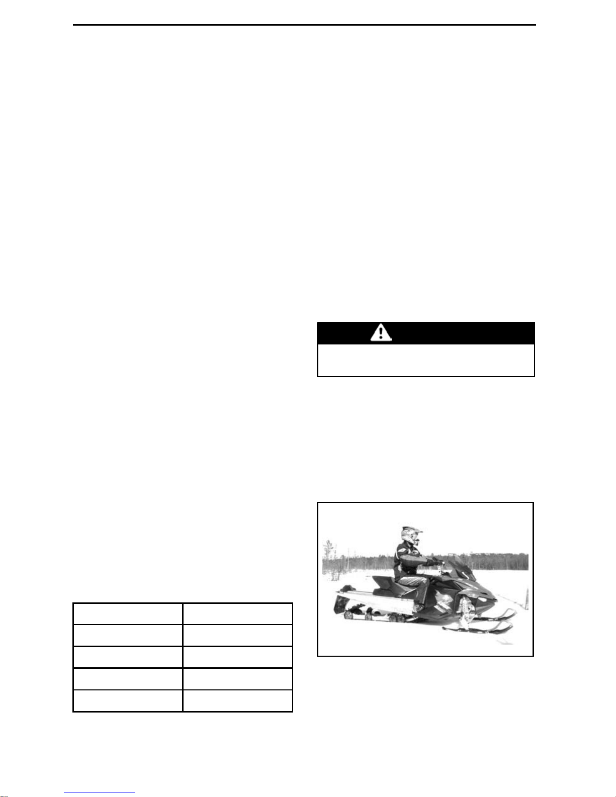
This vehicle may exceed the performance of other vehicles you may have
ridden in the past. Take time to familiarize yourself with your new vehicle.
OPERATOR’S MANUAL 2012
Rave RSTM600
Lynx products are manufactured by BRP.
The following are trademarks of Bombardier Recreational Products Inc. or its subsidiaries.
HPG™
RAVE™
ROTAX
®
TRA™
RS
®
Lynx
®
XPS™
The KYB Pro series is a registered mark of KYB America LLC.
fmo2012enTM
®™ and the BRP logo are trademarks of Bombardier Recreational Products Inc. or its affiliates.
©2011 Bombardier Recreational Products Inc. and BRP US Inc. All rights reserved.
Page 3

FOREWORD
Congratulations on your purchase of
anewLynx
®
snowmobile. Whatever
model you have chosen, it is backed by
the Bombardier Recreational Products
Inc. (BRP) warranty and a network of
authorized Lynx snowmobile dealers
ready to provide the parts, service or
accessories you may require.
At delivery, you were informed of the
warranty coverage and signed the
PREDELIVERY CHECK LIST
to ensure
your new vehicle was prepared to y our
entire satisfaction.
Your dealer is committed to your satisfaction. If you need more information,
please ask your dealer.
Know Before you Go
To learn how to reduce the risk for you
or bystanders being hurt or killed, read
the following sections before you operate the vehicle:
–
SAFETY INFORMATION
–
VEHICLE INFORMATION
.
Also read all safety labels on your
snowmobile.
This vehicle is designed for special purposes and may exceed provincial/state
width limitations for trail riding. Riders
must get all relevant information on local width limitations.
We highly recommend that you take
a safety riding course. Please check
with your dealer or local authorities for
availability in your area.
Failure to follo w the warnings contained in this Operator's Guide can
result in SERIO US INJURY or DEATH.
Safety Messages
The types of safety messages, what
they look like and how they are used in
this guide are explained as follows:
WARNING
Indicates a potential hazard, if not
avoided, could result in serious injury or death.
CAUTION Indicates a hazard
situation which, if not avoided,
could result in minor or moderate
injury.
NOTICE
Indicates an instruction
which, if not followed, could severely damage vehicle components
or other property.
About this Operator's
Guide
This Operator's G uide has been prepared to acquaint the owner and the
operator with this snowmobile and its
various controls, safe riding and maintenance instructions.
The following terminology in regards to
operator, passenger and vehicle configuration is used as follows throughout this guide:
– Operator: refers to the person be-
ing behind the controls and driving
the snowmobile.
– Passenger: refers to a person sit-
ting behind the operator.
– 1-UP: refers to a model designed for
an operator only.
– 2-UP: refers to a model designed to
accommodate one passenger.
Keep this Operator's Guide in the vehicle as you can refer to it for things such
as maintenance, troubleshooting and
instructing others.
Note tha t this guide is availab le in several languages. In the event of any discrepancy, the English version shall prevail.
If you want to view and/or print an extra
copy of your Operator's Guide, sim p ly
visit the following website
www.brpusersclub.com.
_______________
1
Page 4

FOREWORD
The inform atio ns contained in this document are correct at the time of publication. BRP, however, maintains a policy of continuous improvement of its
products without imposing upon itself
any obligation to install th em on products previously manufactured. Due
to late changes, some differenc es between the m a nufactured product an d
the descriptions and/or specifications
in this guide may occur. BRP reserves
the right at any time to discontinue or
change specifications, designs, features, models or equipment without
incurring any obligation upon itself.
This Operator's Guide should remain
with the vehicle when it's sold.
2
_______________
Page 5

TABLE OF CONTENTS
FOREWORD .......................................................................... 1
Know Before you Go............................................................. 1
Safety Messages................................................................. 1
About this Operator's Guide .................................................... 1
SAFETY INFORMATION
GENERAL PRECAUTIONS.......................................................... 8
Avoid Carbon Monoxide Poisoning ............................................. 8
Avoid Gasoline Fires and Other Hazards ....................................... 8
Avoid Burns from Hot Parts ..................................................... 8
Accessories and Modifications ................................................. 8
SPECIAL SAFETY MESSAGES .................................................... 9
RIDING THE VEHICLE .............................................................. 12
Pre-Ride Inspection............................................................. 12
How to Ride ..................................................................... 14
Rider Position (Reverse Operation)............................................ 15
Carrying a Passenger ........................................................... 15
Terrain/Riding Variations ........................................................ 15
Environment..................................................................... 19
IMPORTANT ON-PRODUCT LABELS ............................................ 22
Premix Fuel/Oil Ratio ........................................................... 22
VEHICLE IN FOR MATION
CONTROLS, INSTRUMENTS AND EQUIPMENT .............................. 24
1) Handlebar ..................................................................... 25
2) Throttle Lever................................................................. 25
3) Brake Lever ................................................................... 25
4) Parking Brake Lever.......................................................... 25
5) Engine Cut-off Switch........................................................ 26
6) Emergency Engine Stop Switch ............................................ 26
7) Primer Button................................................................. 27
8) Rewind Starter Handle....................................................... 27
9) Pre-Heat Switch .............................................................. 27
10) High Beam/Low Beam Switch............................................. 27
11) Heated Grips/Heated Throttle Lever Switch.............................. 27
12) Multifunction Analog/Digital Gauge ....................................... 28
13) Front and Rear Bumpers ................................................... 41
14) Drive Belt Guard............................................................. 41
15) Spare Drive BeltHolder..................................................... 42
16) Hood ......................................................................... 43
17) Side Panels .................................................................. 43
FUEL AND OIL....................................................................... 45
Recommended Fuel ............................................................ 45
_______________
3
Page 6

TABLE OF CONTENTS
FUEL AND OIL (cont’d)
Recommended Oil .............................................................. 46
Premix Fuel/Oil Ratio ........................................................... 46
BREAK-IN PERIOD.................................................................. 47
Operation During Break-In...................................................... 47
BASIC PROCEDURES .............................................................. 48
Engine Starting Procedure ..................................................... 48
Vehicle Warm-Up................................................................ 48
Shutting Off the Engine......................................................... 48
RIDING CONDITIONS AND YOUR SNOWMOBILE ............................ 49
Altitude........................................................................... 49
Temperature ..................................................................... 49
Hard Packed Snow.............................................................. 49
SPECIAL PROCEDURES ........................................................... 50
Towing Another Snowmobile .................................................. 50
Emergency Starting Procedure ................................................ 50
TUNE YOUR RIDE .................................................................. 52
Rear Suspension Adjustments................................................. 52
Front Suspension Adjustments................................................ 57
Adjustment Tips According toVehicle Behavior .............................. 59
VEHICLE TRANSPORTATION..................................................... 60
MAINTENANCE INFORMATION
BREAK-IN INSPECTION ........................................................... 62
PERIODIC MAINTENANCE CHART .............................................. 63
MAINTENANCE SCHEDULE (2-STROKE)....................................... 64
PRESEASON PREPARATION...................................................... 66
STORAGE............................................................................ 67
MAINTENANCE PROCEDURES .................................................. 68
Throttle Position Sensor (TPS) ................................................. 68
Air Filter .......................................................................... 68
Engine Coolant .................................................................. 69
Exhaust System................................................................. 69
Spark Plugs ...................................................................... 69
Engine Stopper.................................................................. 70
Brake Fluid ....................................................................... 70
Chaincase Oil .................................................................... 71
Drive Belt ........................................................................ 72
Drive Pulley ...................................................................... 74
Track.............................................................................. 76
Suspension ...................................................................... 79
Skis............................................................................... 80
Fuse .............................................................................. 80
4
_______________
Page 7

TABLE OF CONTENTS
MAINTENANCE PROCEDURES (cont’d)
Lights............................................................................. 80
VEHICLE CARE...................................................................... 83
Post-Operation Care ............................................................ 83
Vehicle Cleaning and Protection ............................................... 83
STORAGE AND PRESEASON PREPARATION .................................. 84
Storage........................................................................... 84
Preseason Preparation ......................................................... 84
TECHNICAL INFORMATION
VEHICLE IDENTIFICATION ........................................................ 86
Vehicle DescriptionDecal ...................................................... 86
Identification Numbers ......................................................... 86
EC DECLARATION OF CONFORMITY............................................ 87
SPECIFICATIONS ................................................................... 88
TROUBLESHOOTING
TECHNICAL GUIDELINES ......................................................... 92
MONITORING SYSTEM ........................................................... 94
Pilot Lamps, Messages and Beeper Codes................................... 94
Fault Codes ...................................................................... 95
WARRANTY
LIMITED WARRANTY VALIDATION.............................................. 98
BRP FINLAND OY INTERNATIONAL LIMITED WARRANTY: 2012 LYNX
®
SNOWMOBILES .................................................................... 99
CUSTOMER INFORMATION
PRIVACY INFORMATION ........................................................ 104
CHANGE OF ADDRESS/OWNERSHIP......................................... 105
_______________
5
Page 8

TABLE OF CONTENTS
6
_______________
Page 9

SAFETY
INFORMATION
________
SAFETY INFORM ATION
________
7
Page 10

GENERAL PRECAUTIONS
Avoid Carbon Monoxide
Poisoning
All engine exhaust contains carbon
monoxide, a deadly gas. Breathing carbon monoxide can cause headaches,
dizziness, d rowsiness, nausea, confusion and eventually death.
Carbon monoxide is a colorless, odorless, tasteless gas that may be present
evenifyoudonotseeorsmellanyengine exhaust. Deadly levels of carbon
monoxide can collect rapidly, and you
can quickly be overcome and unable
to save y ourself. Also, deadly levels of
carbon monoxide can linger for hours
or days in enclosed or poorly ventilated
areas. If you experience any symptoms of carbon monoxide poisoning,
leave the area immediately, get fresh
air and seek medical treatment.
To prevent serious injury or death from
carbon monoxide:
– Never run the vehicle in p oorly ven-
tilated or partially enclosed areas
such as garages, carports or barns.
Even if you try to ventilate engine
exhaust with fans or open windows
and doors, carbon monoxide can
rapidly reach dangerous levels.
– N ev er run the vehicle outdoors
where engine exhaustcanbedrawn
into a building through openings
such as windows and doors.
Avoid Gasoline Fires and
Other Hazards
Gasoline is extremely flammable and
highly explosive. Fuel vapors can
spread and be ignited by a spark or
flame many feet away from the engine. Toreduce the risk of fire or explosion, follow these instructions:
– U se only an approved gasoline con-
tainer to store fuel.
– Stric tly adhere to instructions in
FU-
ELING PROCEDURE
.
– N ever start or operate the engine if
the fuel cap is not properly installed.
Gasoline is poisonous and can cause
injury or death.
– Never siphon gasoline by mouth.
– If you swallow gasoline, get any in
your eye or inhale gasoline vapor,
see your doctor immediately.
If gasoline spills on you, wash with
soap and water and change your
clothes.
Avoid Burns from Hot Parts
The exhaust system and en gine become hot during operation. Avoid contact during and shortly after operation
to avoid burns.
Accessories and
Modifications
Do not make unauthorized modifications, or use attachments or accessories that are not approved by BRP.
Since these changes have not been
tested by BRP, they may increase the
risk of crashes or injuries, and they can
make the vehicle illegal.
Accessory passenger seats approved
by BRP and conforming to SSCC standards may be available for certain models. If such a seat is used, you must
follow the guidelines and recommendations in regards to a passenger in
this guide.
WARNING
Passenger seat must have a strap
or handholdsandmustmeetSSCC
standards.
See your authorized Lynx dealer for
available accessories for your vehicle.
8
________
SAFETY INFORM ATION
________
Page 11

SPECIAL SAFETY MESSAGES
SEVERE INJURY OR DEATH can result if you do not follow these instructions:
– Always make a pre-ride inspection BEFORE you start the engine.
– Throttle mechanism should be checkedforfreemovementandreturn to idlepo-
sition before starting engine.
– A lwa ys attach te th e r cord eye let to clothing before starting the engine.
– Never operate the engine without drive belt guard and brake disk guard securely
installed or, with hood or side panels opened or removed. Never run the engine
without drive belt installed. Running an unloaded engine such as without drive
belt or with track raised, can be dangerous.
– Always engage parking brake before starting the engine.
– Everyone is a beginner the first time he sits behind the controls of a snowmobile
regardless of previous experie nce in driving any other type of vehicle. The safe
use of your snowmobile depends on many conditions such as visibility, speed ,
weather, environment, traffic, vehicle condition and the condition of the opera-
tor.
– Basic training is required for the safe operation of any snowmobile. Study your
Operator's Guide paying particular attention to cautions and w arnings. Join
your local snowmobile club: its social activities and trail systems are planned
for both fun and safety. Obtain basic instructions from your snowmobile dealer,
friend, fellow club member or enroll in your state or provincial safety training
program.
– Any new operator must read and u nderstand all safety labels on the snowmo -
bile, the Operator's Guide before operating the snowmobile. Only allow a new
operator to op erate the snowmobile in a restricted flat a re a, a t least until he is
completely familiar with its op eration . If snowmobile operator's tra inin g course
is offered in your area, have him enroll.
– The performance of some snowmobiles may significantly exceed that of other
snowmobiles you have operated. Therefore, use by novice or inexperienced
operators is not recommended.
– Snowmobiles are used in many areas and in many snow conditions. Not all
models perform the same in similar conditions. Always consult your snowmo-
bile dealer when selecting the snowmobile model for your particular needs and
uses.
– Injury or death may result to the snowmobile operator or bystander if the snow-
mobile is used in risky conditions which are beyond the operators's or snowmo-
bile's capabilities or intended use.
– BRP recommends the operator has at least 16 years old of age.
– It is very important to inform any operator, regardless of his experience, of the
handling characteristics of this snowmobile. The snowm obile configuration,
such as ski stance, ski type, suspension type, track length, width and type vary
from a model to another. The snowmobile handling is greatly influenced by
these characteristics.
– The novice operator should become fa miliar with th e snowmobile through prac-
tice on a level area at slow speeds before venturing far afield.
________
SAFETY INFORM ATION
________
9
Page 12

SPECIAL SAFETY MESSAGES
– Know your local laws. Federal, state, provincial and local government agencies
have enacted laws and regulations pertaining to the safe use and operation of
snowmobiles. It is your responsibility as a snowmobiler to learn and obey these
laws and regulations. Respect and ob se rv ance will result in safer sno wmobiling
for a ll. Be a w a re of the liability property damages and insurance laws regardin g
your equipment.
– Speeding can be fatal. In many cases, you cannot react or respond quickly
enough to the unexpected. Always ride at a speed which is suitable to the trail,
weather conditions and your own ability. Know your lo cal rules. Spe ed limit
maybeineffectandmeanttobeobserved.
– Always keep right hand side of the trail.
– Always keep a safe distance from other snowmobiles and bystanders.
– Remember, promotional material may show risky maneuvers performed by
professional riders under ideal and/or controlled conditions. You should never
attempt any such risky maneuvers if they are beyond your le vel of riding ability.
– Never ride this vehicle under influence of alcohol or drugs. They slow reaction
time and impair judgement.
– Yoursnowmobileisnotdesigned to be operatedonpublicstreets,roadsorhigh-
ways.
– Avoid road traveling. If you must do so, and it is permitted, reduce speed. The
snowmobileisnotdesignedtooperate or turn on paving. When crossing a road,
make a full stop, then look carefully in both directions before crossing at a 90°
angle. Be wary of parked vehicles.
– Snowmobiling at night can be a delightful experien ce but because of reduce d
visibility, be extra cautious. Avoid unfam iliar terrain and be sure your lights are
working. Always carry a flashlight and spare light bulbs.
– Never remove any original equipment from your snowmobile. Each vehicle
has many built in safety features. Such features include various guards an d
consoles, plus reflective materials and safety labels.
– Nature is w onderful but don't let it distract your attention from driving. If you
want to truly appreciate winter's scenery, stop your snowmobile on the side of
the trail so that you don't become a hazard to others.
– Fences represent a very serious threat for both you and your snowmobile. Give
a wide berth to telephone poles or posts.
– Hidden wires unseen from a distance can cause serious accidents.
– Always wear an approved safety helmet, eye protection and a face shield.
– Be aware of inherent risks associated with riding off trails, such as avalanche
and other natural or m an made hazards or obstacles.
– Tailgating another snowmobile should b e avoided. If the snowmobile in front of
you slows for any reason, its operator and passenger could be harmed through
your neglect. M aintain a safe stopping distance between you and the snowmo-
bile in front of you. Depending on the terrain condition, stopping may require a
littlemorespacethanyouthink. Play it safe. Be prepared to use evasive driving.
– Venturing out alone with your snowmobile could also be hazardous. You could
run outoffuel,haveanaccident, or damageyoursnowmobile. Remember, your
snowmobile is capable of traveling further in half an hour than you may be able
to walk in a day. Use the “buddy system”. Always ride with a friend o r member
of your snowmobile club. Even then, tell someone where you are going and the
approximate time you plan to return.
10
_______
SAFETY INFORMATION
________
Page 13

SPECIAL SAFETY MESSAGES
– Mea dow s sometimes have low areas where water accumulate and freezes
over in winter. This ice is usually glare ice. Attempting to turn or brake on
this surface could caus e your vehicle to spin out of control. Never brake or
attempt speeding or turning on glare ice. If you do happen to travel over such a
condition, reduce speed by carefully releasing the throttle.
– Never “jump” with your snowmobile.
– When riding in group, do not “gun” the throttle. Snow and ice can be thrown
back into the path of a following snowmobile. In addition, when “gunning” the
throttle, the vehicle digs into and leaves an irregular snow surface for others.
– Riding in group is fun and enjoyable but don't show off or overtake others in the
group. A less experienced operator might try to do the sam e as you and fail.
When riding with others, limit your abilities to the experience of others .
– In case of an emergency, press down on the engine emergency stop switch,
then apply brake .
– A lways engage parking brake when veh icle is n ot in use.
– Never run the engine in a non-ventilatedarea and/or if vehicle is left unattended.
– Ensure the path behind is clear of obstacles or bystanders before proceeding in
reverse.
– Always remove the tether cord cap from engine cut-off switch when vehicle is
not in operation in order to prevent accidental engine starting, to avoid unautho-
rized use by children or others or theft.
– NEVER stand behind or near a rotating track. Debris could be projected causing
severe injuries. Toremovepackedsnow or ice, stop engine, tilt and hold vehicle
on its side and use screwdriver.
– Do not stud the track unless it has been approvedforstuds. At speed, a studded
track that has not been approved for studs could tear and separate from vehicle.
See an authorized Lynx dealer for current specific studding availability and appli-
cations.
– You may stud the track on this vehicle model. However,you MUST only use the
BRPapprovedtypestudforuseonLynxsnowmobiles. DONOTEVERusecon-
ventional studs because the track thickness is thinner then our standard tracks.
The stud could tear off of track and separate from vehicle.
– Always wear an approved helmet and follow the same dressing guidelines as
those recommended for the operator and described in this guide.
– M ake sure that you are able to achieve a stable stance, both feet resting posi-
tively on the footboards of footrests with good grip, and that you are able to hold
on firmly to the handholds.
– Do not forget, with 2-UP models, theoperatorisresponsible for the safetyofthe
passenger. A lw ays remember that the snowm ob ile handling, s tability and brak-
ing distance may be affected when riding with a passenger.
– B efore riding the vehic le, ask your passenger to inform you to slow d own or
stop immediately if he feels uncomfortable or insecure during the ride. Keep a
watchful eye on your passenger while riding.
________
SAFETY INFORMATION
________
11
Page 14

RIDING THE VEHICLE
Each op erator has a responsibility to
ensure the safety of other recre ation ists or bystanders.
You are responsible for proper operation of your vehicle as well as training
thosewhomyouallowtorideordrive.
There may be noticeable handling and
performance differences from one
snowmobile to the ot her.
A snowmobile is relatively simple to
operate b ut like any other ve h icle or
mechanical equipment, it ca n be hazardous if you are reckless, thoughtless
or inattentive. We encourage you to
have an Annual Safety Inspection of
your snowmobile. Please contact an
authorized Lynx dealer for further details. Fin ally, we urge you to v isit an
authorized Lynx dealer pe riod ically for
regular and safety maintenance, as
well as snowmobile accessories you
may require.
Before venturing on the trails, operate
the sn owmobile in a restricted flat area
until you are complete ly familiar with
its operation and feel comfortable that
you can safely tackle a more demanding task. Have an enjoyable and safe
ride.
Pre-Ride Inspection
WARNING
The pre-operation check is very
important prior to operating the
vehicle. Always check the proper
operation of critical controls,
safety features and mechanical
components before starting.
Before Starting the Engine
1. Remove snow and ice from body including lights, seat, footrests, controls and instruments.
2. Verifythatairsilencer prefilterisfree
of snow.
3. Verify that skis and steering operate
freely. Check corresponding action
of skis versus handlebar.
4. Check fuel level. Replenish if necessary.
5. Check coolant and brake fluid levels.
In case of a low level, contact an authorized Lynx dealer.
6. All storage compartments must be
properly latched and they must not
contain any heavy or breakable objects. Hood and side panels must
be also properly latched.
7. Check track condition. Remove
snow or ice if necessary.
8. Check rear suspension slider shoes
condition.
9. Activate the throttle control le ver
several times to check that it operates easily and smoothly. It must return to idle position when released.
10. Activat e the brake lever and make
sure the brake fully applies be f ore
the brake control lever touches the
handlebar grip. It must return to
the rest position when released.
11. Apply parking brake and check if it
operates properly. Leave parking
brake applied.
12
_______
SAFETY INFORMATION
________
Page 15

RIDING THE VEHICLE
After Engine is Started
For proper engine starting procedure,
refer to the
ENGINE STARTING PRO-
CEDURE
section.
1. Check headlights high beam and
low beam, taillight, stop light and
pilot lamps operation.
NOTE: You may need to detach tether
cord from your clothes to check lights.
In such a case, attac h cord as soon
as you get back at the controls of the
snowmobile.
2. Check the engine cut-off switch (by
pulling teth er cord cap) and emergency engine stop switch operation.
3. Release parking brake.
4. Refer to the
VEHICLE WARM UP
section and follow instructions.
Pre-Ride Check List
ITEM OPERATION
✔
Body including seat, footrests,
lights, controls and instruments
Check condition and remove snow or ice.
Air silencer prefilter
Check condition and remove snow or ice.
Steering system Check for free movement and proper action.
Skis and runners Check condition.
Fuel
Check level and replenish if necessary.
Coolant
Check level. If low, contact an authorized Lynx
dealer.
Brake fluid
Check level. A low fluid level indicates a leak or
worn brake pads. Contact an authorized Lynx
dealer.
Storage compartment
Check for proper latching an d no heavy or
breakable objects.
Throttle lever
Check for proper action.
Track
Check condition and remove snow or ice.
Rear suspension slider shoes
Check condition.
Brake lever
Check for proper operation.
Parking device
Check for proper operation.
Emergency engine stop switch
and e ngine cut-off switch
Check for proper action. Tether cord must be
attached to operator clothing eyelet.
Lights
Check for proper operation.
________
SAFETY INFORMATION
________
13
Page 16
RIDING THE VEHICLE
How to Ride
Riding Gear
Proper snowmobile clothing should
be worn. It should be comfortable
andnottootight. Alwayscheckthe
weather forecast before going on a
ride. Dress for the coldest weather
expected. Thermal underwear next to
theskinalsoprovidesagoodinsulation.
Wear an approved helmet at all times
for safety and comfort. They provide both warmth and reduce injury.
A stocking type cap, balaclava and
face mask should always be carried
or worn. Goggles or a face shield that
attach to the helmet are indispensable.
Carry colored lens if your helmet is not
equipped so.
Hands should be protected by a pair
of snowmobile gloves or mitts which
have sufficient insula tio n and allow use
of thumbs and fingers for operation of
controls.
Rubber bottom boots with either a nylon or a leather top, with removable felt
liners are best suited for snowmobiling.
You should keep yourself as dry a s possible when snowmobiling. When you
come indoors, take your snow mobile
suit and boots off and make c ertain
they dry properly.
Do not wear long scarfs and loose apparels that could get caught in moving
parts.
What to Bring
First aid kit Mobile phone
Knife
Spare spark plugs
Flashlight Friction tape
Trail map
Spare drive belt
Snack
Toolkit
Rider Position (Forward Operation)
Your riding pos ition and b alance are
the two basic principles of making you r
snowmobile go where you want it to.
When turning on the side of a hill, you
must be ready to shift body weight to
help it turn in the desired direction. You
must never attempt this maneuvering
by placing feet outside of the vehicle. Experience will teach you how
much lean to put into turns at differ en t
speeds and how much you will have
to lean into a slope to maintain proper
balance.
Generally, the riding position for best
balance and control is sitting. However, the posting, kneeling or standing
positions are also used under certain
conditions.
WARNING
Do not attempt any maneuvers if
they are beyond your abilities.
Sitting
Feet on the running boards, body midway back on seat is an ideal position
when operating the snowmobile over
familiar, smooth terrain. Knees and
hips should remain flexible to absorb
shocks.
fmo2008-003-001
Posting
A semi-sitting position with the body
off the seat and thefeetunderthebody
in a sort of squatting posture, thus al-
14
_______
SAFETY INFORMATION
________
Page 17

RIDING THE VEHICLE
lowing the legs to absorb the shocks
when traveling over uneven terrain.
Avoid abrupt stops.
fmo2008-003-002
Kneeling
This position is achieve d by placing
one foot firmly on the running board
and the opposite knee on the seat.
Avoid abrupt stops.
fmo2008-003-003
Standing
Place both feet on the running boards.
Knees should be flexed to absorb the
shock from surface bumps. This is an
effective position to see better and
to shift weight as conditions dictate.
Avoid abrupt stop.
fmo2008-003-004
Rider Position (Reverse
Operation)
We recommend sitting on your snowmobile when operating in reverse.
Avoid standing up. Your weight could
shift forward against throttle lever
while o perating in reverse, causing
an unexpected acceleration.
WARNING
Unexpected acceleration when
snowmobile operates in reverse
can cause a loss of control.
Carrying a Passenger
Certain snowmobiles are designed for
an operator only (1-UP), and others can
allow one passenger only (2-UP). Make
sure to identify and respect the warnings according to your specific models.
Even when a passenger is allowed,
this person must b e physically fit for
snowmobiling.
Terrain/Riding Variations
Groomed Trail
On a maintained trail, sitting is the
most preferred riding position. Do not
race and, above all, keep to the right
hand side of the trail. Be prepared
for the unexpected. Observe all trail
signs. Do not zigzag from one side of
the trail to the other.
________
SAFETY INFORMATION
________
15
Page 18

RIDING THE VEHICLE
Ungroomed Trail
Unless there has been a fresh snowfall you can expect “washboard” and
snowdrift conditions. Taken at excessive speeds, such conditions can be
physically harmful. Slow down. Hold
on the handlebar and assume a posting position. Feet should be under the
body assuming a crouched position to
absorb any jarring effect. On longer
stretches of “washboard” trails, the
kneeling position of one knee on the
seat can be adopted. This provides a
certain amount of comfort, while at the
same time keeps the body loose and
capable of vehicle control. Beware of
hidden rocks or tree stumps partially
hidden by a recent snowfall.
Deep Snow
In deep “powder” snow, your vehicle
could begin to “bog” down. If this occurs,turninaswideanarcaspossible
and look for a firmer base. If you do get
“bogged”, and it happens to everyone,
do not spin your track as this makes the
vehicle sink deeper. Instead, turn the
engine off, get off and move the back
of the vehicle onto new snow. Then
tramp a clear path ahead of the vehicle. A few feet will generally suffice.
Restart the engine. Assume the standing position and rock the vehicle gently
as you steadily and slowly apply th e
throttle. Depending on whether the
front or rear end of the vehicle is sinking, your feet should be placed on the
opposing end of the running boards.
Never place foreign material beneath
the track for support. Do not allow anyone to stand in front of, or to the rear
of, the snowmobile with the engine
running. Stay away from the track.
Personal injury will result if co ntact is
made with the revolving track.
Frozen Water
Traveling frozen lakes and riv ers can be
fatal. Avoid waterways. If you are in
an unfamiliar area, ask the local authorities or residents about the ice condi-
tion, inlets, outlets, springs, fast moving currents or other hazards. Never
attempt to operate your snowmobile
on ice that may be too weak to support you and the vehicle. Operating
a snow m obile on ice or icy surfaces
can be very dangerous if you do not
observe certain precautions. The very
nature of ice is foreign to good control of a snowmobile or any vehicle.
Traction for starting, turning or sto pping is much less than that on snow.
Thus, these distances can be multiplied manyfold. Steering is minimal,
and u ncontrolled spins are an ever
present danger. When operating on
ice, drive slowly with caution. Allow
yourself plenty of room for stopping
and turning. This is especially true at
night.
Hard Packed Snow
Don't underestimate hard packed
snow. It can be difficult to negotiate
as both skis and track do not have as
much traction. Best advice is to slow
down and avoid rapid acceleration,
turning or braking.
Uphill
There are two types of hills you can en counter — the open hill on which there
are few trees, cliffs or other obstacles,
and a hill that can only be climbed directly. On an op en hill, the approach is
to climb it by side hilling or slaloming.
Approachatanangle. Adopt a kneeling
position. Keep your weight on the uphill side at all times. Maintain a steady,
safe speed. Continue as far as you can
in this directio n, then switch to a n opposite hill angle and riding position.
A direct climb could present problems.
Choose the standing position, a ccelerate before you start the climb and then
reduce throttle pressure to prevent
track slippage.
In either case, vehicle speed should be
as fast as the incline demands. Always
slow down as you reach the crest. If
you cannot proceed further, don't spin
16
_______
SAFETY INFORMATION
________
Page 19

RIDING THE VEHICLE
your track. Turn the engine off, free the
skis by pulling them out and downhill,
place the rear of the snowmobile uphill
restart the engine and ease it out with
slow even throttle pressure. Positio n
yourself to avoid tipping over, then descend.
Downhill
Downhill driving requires that you have
full control of your vehicle at all tim es.
On steeper hills, keep your center of
gravity low and both hands on the handlebar. Maintain slight throttle pressure and allow the machine to run
downhill with the engine operating.
If a higher than safe speed is reached,
slow down by braking but apply the
brake with frequent light pressure.
Never jam the brake and lock the track.
Side Hill
When crossing a side hill or traversing up o r downhill, certain procedures
must be followed. All riders should
lean towards the slope as required for
stability. The pre ferre d operating positions are the kneeling position, with
thekneeofthedownhilllegonthe
seat and the foot of the uphill leg on
the running board, or the posting position. Be prepared to shift your weight
quickly as need ed. Side hills and steep
slopes are not recommended for a beginner or a novice snowmobiler.
Slush
Slush should be avoided at all times.
Always check for slush before starting
across any lake or river. If dark spots
appearinyourtracks,getofftheice
immediately. Ice and water can be
thrown rearward into the path of a following snowmobile. Getting a vehicle
out of a slush area is strenuous and in
some cases, impossible.
Fog or Whiteout Conditions
On land or water, fog or visibility-limiting snow can form. If you have to
proceed into the fog or heavy snow, do
so slowly with your lights on and watch
intently for hazards. If you are not sure
of your way, do not proceed. Keep a
safe distance behind other snowmobilers to improve visibility and reaction
time.
Unfamiliar Territory
Whenever you enter an area that is
new to you, drive with extreme caution. Go slow enough to recognize
potential hazards such as fences or
fence posts, brooks crossing your
path, rocks, sudden dips, guy wires
and cou ntless other obstacles which
could result in a termination of your
snowmobile ride. Even when following existing tracks, be cautious.
Travel at a speed so you can see what
is around the next bend or over the top
of the hill.
Bright Sunshine
Bright sunny days can considerably
reduce your vision. The glare from
sun and snow may blind you to the extent that you cannot eas ily distinguish
ravines, ditches or other obstacles.
Goggles with colored lenses should always be worn under these conditions.
Unseen Obstruction
There may be obstructions hidden
beneath the s now. Driving off established trails and in the woods requires reduced speed and increased
vigilance. Driving too fast in an area
can make even minor obstacles very
hazardous. Even hitting a small rock
or stump could throw your snowmobile out of control and cause injury to
its riders. Stay on established trails
to reduce your exposure to hazards.
Be safe, slow down and enjo y the
scenery.
Hidden Wires
Always be on the lookout for hidden
wires, especially in areas that may
have been farmed at one time or another. Too many accidents have been
________
SAFETY INFORMATION
________
17
Page 20
RIDING THE VEHICLE
caused by running into wires in the
fields, guy wires next to poles and
roads, and into chains and wires used
as road closures. Slow speeds are a
must.
Obstacles a nd Jumping
Unplanned jumps of snowdrifts, snowplow ridges, culverts or indistinguishable objects can be dangerous. You
can avoid them by wea rin g the proper
color lenses or face shields and by operating at a lower speed.
Jumping a snowmobile is an unsafe
and dangerous practice. However, if
the trail does suddenly drop away from
you, crouch (stand) towards the rear
ofthevehicleandkeeptheskisup
and straight ahead. Apply pa rtial throttle and brace yourself for the impact.
Knees must be flexed to act as shock
absorbers.
Tur ning
Depending on terrain conditions, there
are two preferred ways to turn or corner a snowmobile. For most snow
surfaces, “body english” is the key to
turning. Leaning towards the inside of
the turn and positioning body weight
on the inside foot will create a “banking” condition ben eath the track. By
adopting this position and positioning
yourself as far forwa rd as possible,
weight will be transferred to the inside
ski.
On occasion, you will find that the only
way to turn the vehicle about in deep
snow is to pull the snowmobile around.
Do not over-exert yourself. Get ass istance. Remember to always lift u sing
your legs as opposed to your back.
fmo2008-003-005
Road Crossing
In some cases, you will be approaching the road from a ditch or snowbank.
Choose a place where you know you
can climb without difficu lty. Use the
standing position and proceed with
only as much speed needed to crest
the bank. Stop completely at the top
of the bank and wait for all traffic to
clear. Judgethedroptotheroadway.
Cross the road at a 90° angle. If you encounter another snowbank on the opposite side, position your feet near the
rear of the vehicle. Remember, your
snowmobile is not designed to operate on bare pavement and steering on
this type of surface is more difficult.
Railroad Crossing
Never rid e on railroad tracks. It is illegal. Railroad trac ks and railroad
rights-of-way are private property. A
snowmobile is no match for a train.
Before crossing a railroad track, stop,
look and listen.
Night Rides
The amount of natural and artificial
light at a given time can affect your
ability to se e or to be seen. Nig httime
snowmobiling is delightful. It can be
a unique experie nce if you ackn owledge your reduced visibility. Before
you start, make certain your lights
are clean and work properly. Drive
at speeds that will allow you to stop
in time when you see an unknown or
dangerous object ahead. Stay on established trails and never operate in
18
_______
SAFETY INFORMATION
________
Page 21

RIDING THE VEHICLE
unfamiliar territory. Avoid rivers and
lakes. Guy wires, barbed wire fences,
cabled road entrances and other objects such as tree limbs are difficult
to see at night. Never drive alone. Always carry a flashlight. Keep away
from residential areas and respect the
right of others to sleep.
Group Riding
Before starting out, designate a “trail
boss” to lead the party and another person to follow-up at the end of the party.
Ensure that all members of the party
are aware of the proposed route and
destination. Make certain that you are
carrying all necessary tools and equipment and that you have sufficient fuel
to complete the trip. Never overtake
the trail boss or, for that matter, any
other snowmobile. Use down-the-line
hand signals to indicate hazards or intent of direction change. Assist others
whenever necessary.
ItisalwaysIMPORTANTtokeepa
safe distance between each snowmobile. Always maintain a safe interval
and allow sufficient stopping distance.
Don't be a tailgater. Know the position
of the machine ahead.
Signals
Ifyouintendtostop,raiseeitherhand
straight above your head. A left turn is
indicated by extending your left hand
straight out in the proper direction. For
right turns, extend the left arm and
raise the hand to a vertical position so it
forms a rig ht angle at the elbow. Every
snowmobiler should relay any signal to
the ones behind.
Trail Stops
Whenever possible, pull off the trail
when you stop. This will reduce the
hazard to other snowmobilers using
the trail.
Trails and Signs
Trail signs are used to control, direct or
regulate the use of snowmobiles on
trails. Become familiar with all signs
used in the area where you are snowmobiling.
Environment
Wildlife compliments yo ur snowmobiling day. Snowmobile tracks p rovide
firm ground o ver which animals can
travel from area to area. Do not violate
this privilege by chasing or harassing
wildlife. Fatigue and exhaustion can
lead to animal's death. Avoid areas
posted for the protection or feeding of
wildlife.
If you happen to be fortunate enough
to see an animal, stop your snowmobile and observe quietly.
The guidelines that we support are not
designed to limit your sno wmobiling
fun, but to preserve the beautiful freedom that you can experience only on
a snowmobile! These guidelines will
keep snowmobilershealthy,happyand
able to introduce others to what they
know and enjoy about their favorite
winter pastime. So, the next time you
hit the trails on a cool, crisp and clear
winter day, we ask you to remember
that you are paving the way for the future of our sport. Help us lead it down
the right path ! From all of us at BRP,
thank y ou for doing your share.
There is nothing more exhilarating than
snowmobiling. Venturing onto snowmobile trails that criss-cross wild areas
is an exciting and healthy winter sport.
However, as the number of people using these recreational parks increases,
so does the potential for damage to the
environment. Abuse of land, facilities
and resources inevitably leads to restrictions and closures of both private
and public land.
________
SAFETY INFORMATION
________
19
Page 22

RIDING THE VEHICLE
In es sence, the greatest threat to our
sport, is all around us. Which leaves
us with one logical choice. When we
snowmobile, we must always ride responsibly.
The vast majority respect the law and
the environment. Each of us must set
an example for those who are new to
the sport, young and old alike.
It is in every one's best inte re st to tread
lightly into our recreational areas. Because, in the long run, to protect the
sport we must preserve the environment.
Recognizing the importance of this issueandtheneedforsnowmobilersto
do their share in preserving areas that
make it possible to enjoy our sport,
BRP has developed the “Light Treading Is Smart Sledding” campaign for
snowmobilers.
Light Treading refers to more than the
thread of our trac ks. It's a statement
of concern, respect and willingness
to take the lead and take action. I t applies to the environment in general, its
proper care and maintenance, its natural inhabitants and all enthusiasts and
the public at large who enjoy the great
outdoors. With this theme, we invite
all snowmobilers to remember that respecting the environment is not only
critical to the future of our industry but
to future generations.
Light Treading in no way suggests you
should curb your appetite for snowmobiling fun! It simply me an s tread with
respect!
The fundamental ob je ctive of Light
Treading is one of respect for where
and how you ride a snowmobile.
You're a light treader when you follow
the principles below.
Become informed. Obtain maps, regulations and other information from
the Forest Service or from other public land agencies. Learn the rules and
follow them and that goes for spee d
limits, too!
Avoid running over young trees,
shrubs, and grasses and don't cut
wood. On flatlands or areas where trail
riding is popular, it's important to ride
only where authorized. Remember,
there is a link between protecting your
environment and your own safety.
Respect wild life and be particularly
sensitive o f animals that are rearing
young or suffering from food shortage.
Stress can sap scarce energy res erves.
Refrainfromridinginareaswhereonly
animals are intended to tread!
Obey gate closures and regulatory
signs and remember, light treaders
don't litter!
Stay out of wilderness areas. They're
closed to all vehicles. Know where the
boundaries are.
Obtain permission to travel across
private land. Respect the rights of
landowners and other people's privacy. Remember, snowmobile technology has lowered the noise factor
considerably, but you still shouldn't rev
your engines where quiet “is the order
of the day”.
Snowmobilers know all too well the efforts that have been made throughout
the sport's history to enjoy access to
areas where people can snowmobile
safely and responsibly. This effort continues today, as strong as ever.
Respectingtheareaswhereweride...
wherever they may be... is the only
way to ensure their future enjoyment.
That's one major reason why we know
you'll agree that Light Treadingissmart
sledding! And ther e are m ore.
Enjoying the opportunity to see winter
and all its natural majestic wonders,
is an experience cherished by snowmobilers. Light Treading will preserve
this opportunity and w ill make it possible for us to expose others to the
beauty of winter and the unique thrill of
our sport! Light Treading will help our
sport to grow!
20
_______
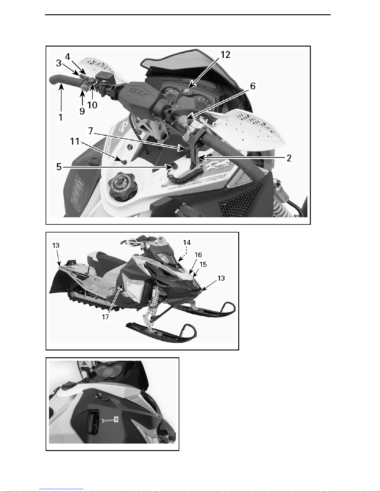
SAFETY INFORMATION
________
Page 23

RIDING THE VEHICLE
Finally, Light Treading is the sign of a
smart snowmobiler. You don't have
to leave big tracks or careen through a
virgin forest to show you can ride. So
whether you're driving a high performanceLynx, a sporty RAVE
®
snowmobile or any other make or model, show
you know what you're doing. Show
you know how to send snow flying and
make tracks with a light touch!
________
SAFETY INFORMATION
________
21
Page 24
IMPORTANT ON-PRODUCT LABELS
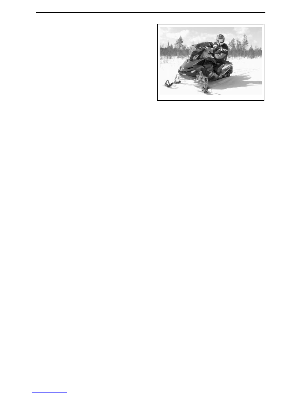
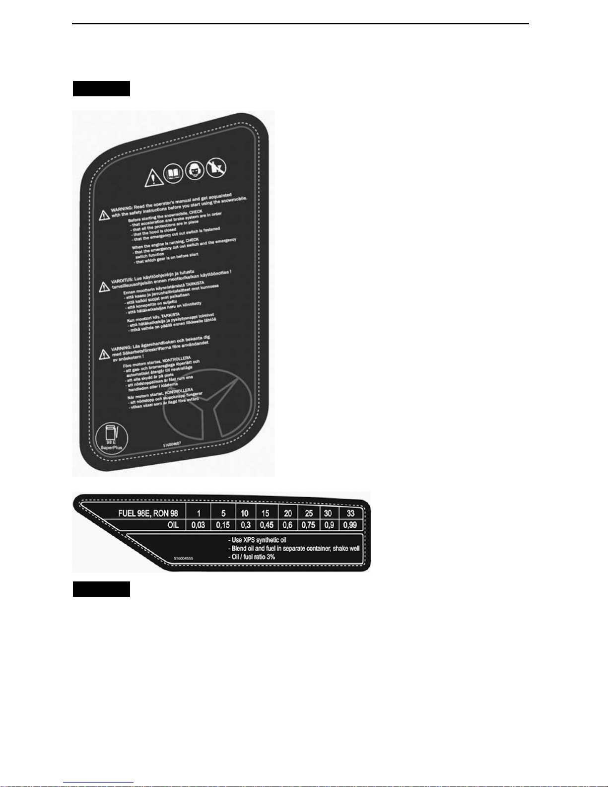
Premix Fuel/Oil Ratio
NOTICE
Warning label on the vehicle
NOTICE
Fuel / oil label on the vehi-
cle
22
_______
SAFETY INFORMATION
________
Page 25

VEHICLE
INFORMATION
_______________
23
Page 26
CONTROLS, INSTRUMENTS AND EQUIPMENT
fmo2011-007-007_c
fmo2011-007-010_d
fmo2011-007-011_a
24
______________
Page 27
CONTROLS, INSTRUMENTS AND EQUIPMENT
1) Handlebar
The handlebar controls the steering
of the snowmobile. As the handlebar
is rotated to right or left, the skis are
turned right or left to steer the snowmobile.
2) Throttle Lever
Throttle lever is located on the RH side
of handlebar.
Designed to be thumb activated.
When squeezed, it increases the engine speed and engages the transmission. When released, engine speed
returns automatically to idle.
WARNING
Test the throttle lever operation
each time before starting the engine. The lever must return to its
original position once released.
Otherwise, do not start engine.
3) Brake Lever
Brake lever is located on the LH side of
handlebar.
When squeezed, brake is applied.
When released, it autom atically returns to its original position. Braking
effect is proportional to the pressure
appliedontheleverandtothetypeof
terrain and its snow coverage.
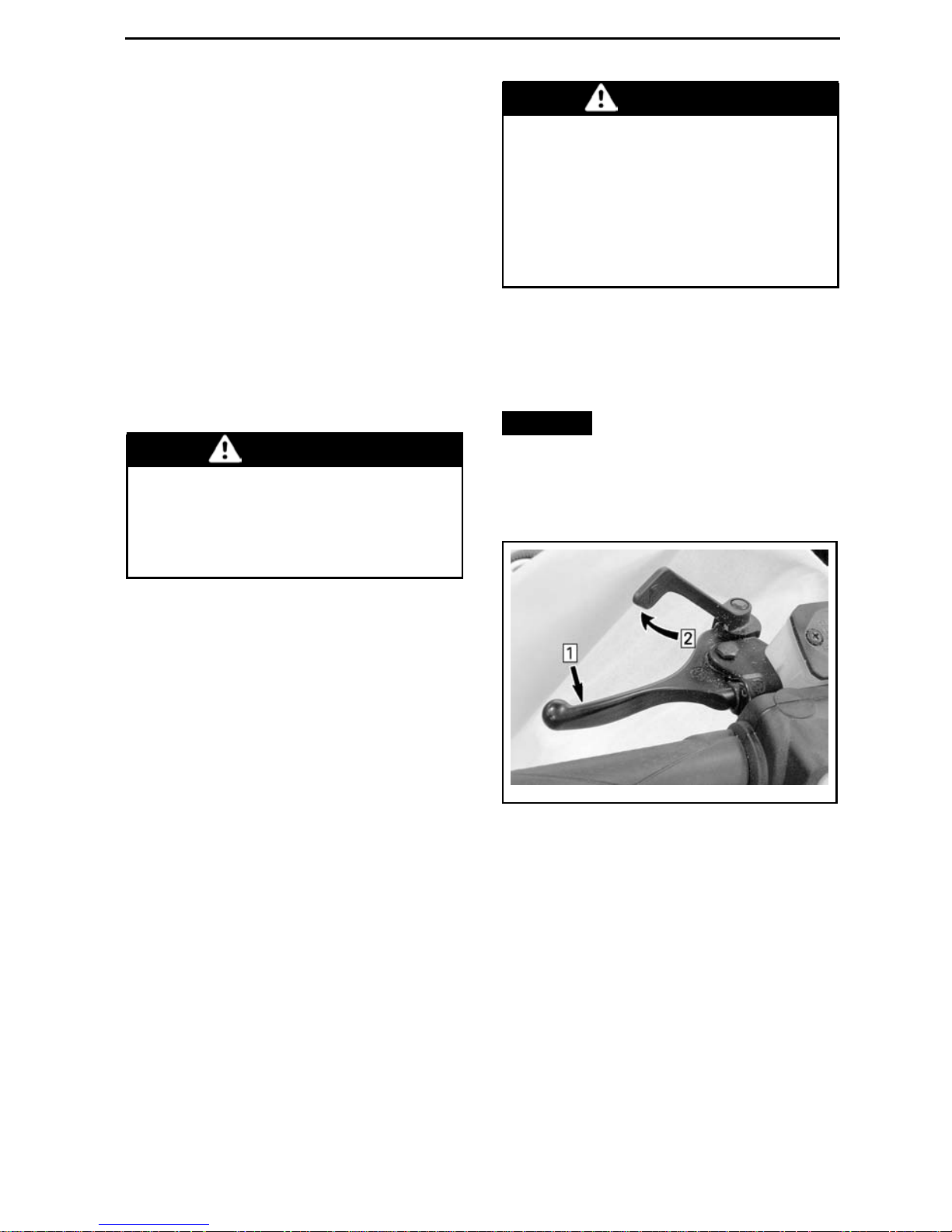
4) Parking Brake Lever
Parking brake is located on the LH side
of handlebar.
Parking brake should be used whenever snowmobile is parked.
WARNING
Make sure parking brake is fully
disengaged before operating the
snowmobile. When you ride the
vehicle, brake pads that are caused
to drag by a continuous pressure
on the lever may cause damage to
the brake system and cause loss of
braking capacity and/or fire.
To Engage Parking Brake
Apply and hold brake, then lock brake
lever using the p arking brake lever as
shown.
NOTICE
Parking brake position
can vary depending on brake pads
wear. Ensure when the parking
brake is applied that the vehicle
stays securely in place.
mmo2009-005-006_a
TYPICAL — ENGAGE MECHANISM
Step 1: Apply and hold brake
Step 2: Lock brake lever using parking brake
lever
To Release Parking Brake
Squeeze brake lever. Locking lever will
automatically re turn to its original position. Always release parking brake before riding.
_______________
25
Page 28
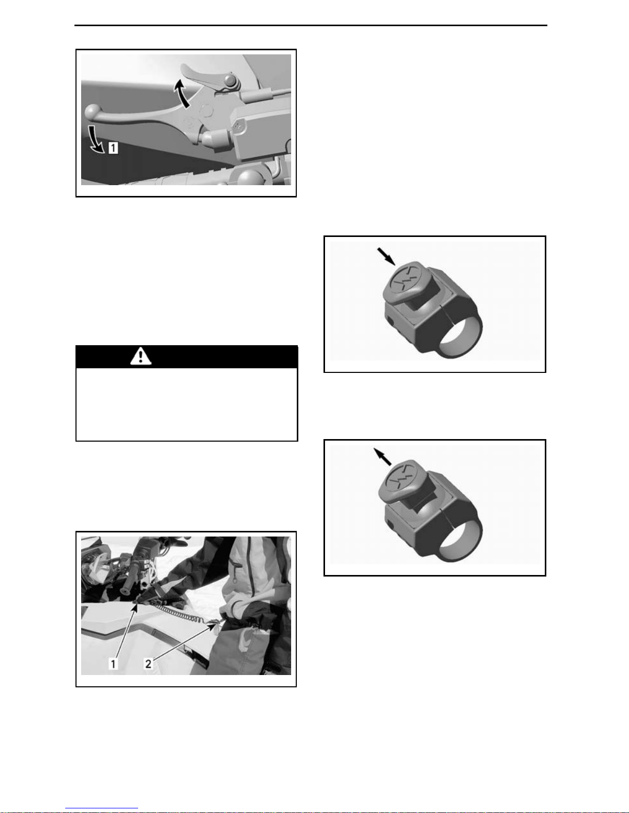
CONTROLS, INSTRUMENTS AND EQUIPMENT
mmo2008-007-011_b
TYPICAL — RELEASE MECHANISM
Step 1: Squeeze brake lever
5) Engine Cut-off Switch
General
When the tether cord cap is removed,
it shuts the engine off preventing
snowmobile to runaway if the operator falls off the vehicle accidently.
WARNING
Always remove the tether cord cap
when vehicle is not in operation in
order to prevent accidental engine
starting, to avoid unauthorized use
bychildrenorothersortheft.
Operation
Attach tether cord eyelet to clothing,
then snap cap over post before starting
engine.
mmo2008-003-012_a
TYPICAL
1. Snap over post
2. Attach to clothing
If emergency engine shut off is required, pull tether cord cap from post
completely.
6) E m ergen cy Engine
Stop Switch
The emergency engine stop switch is
located on the RH side of handlebar.
To stop the engine in an emergency,
select OFF position (down) and simultaneously apply the brake.
mmo2007-009-038_a
OFF POSITION
To allow eng ine starting , the switch
must be in the ON position (UP).
mmo2007-009-038_b
ON POSITION
All operators of the snowmobile
should familiarize themselves with the
function of this device by using it several times on first outing and whenever
stopping the engine thereafter. This
engine shut off procedure will become
a reflex and will prepare operators for
emergency situations requiringits use.
26
______________
Page 29
CONTROLS, INSTRUMENTS AND EQUIPMENT
WARNING
If the switch has been used in an
emergency caused by a suspected
malfunction, the source of the malfunction should be determined
and corrected before restarting
engine. See an authorized Lynx
dealer for servicing.
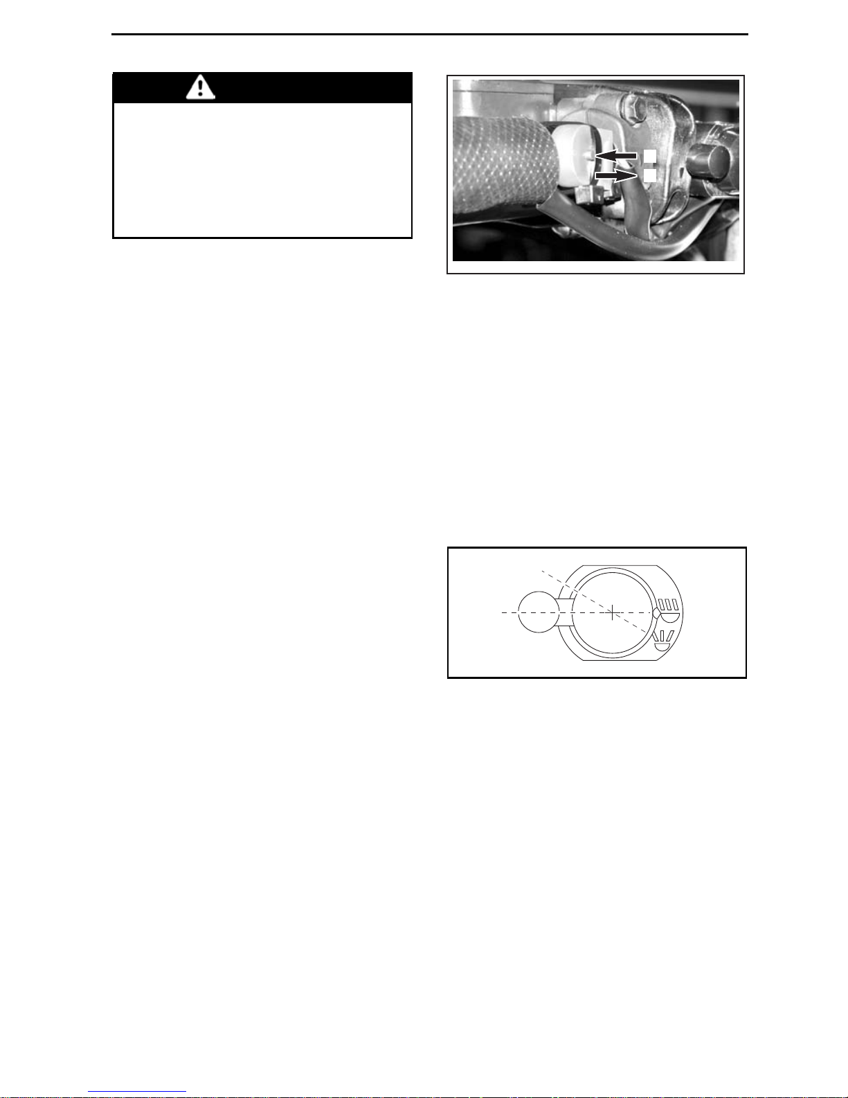
7) Primer Button
Pull and push button. It is not necessary when engine is warm.
To prime, activate button until a pumping resistance is felt. From this point,
pump 2 or 3 times to in je ct fue l in intake manifold. After priming, ensure
that primer button is pushed back.
NOTE: In very cold temperature, it is
recommended to rotate primer button
3 - 4 turns prio r to pulling it. Th is will
eliminate the possibility of sticking.
8) Rewind Starter Handle
Auto-rewind type located on right hand
side of snowmobile. To engage mechanism, pull handle slowly until a resistance is felt then pull vigorously.
Slowly release handle.
9) Pre-Heat Switch
Racing Application Only
NOTE: This switch must be removed
on vehicles modified for warranty validation.
1
A33E0SA
2
1. Button depressed: Pre-heat timing curve
2. Button released: Normal tim ing curve
After starting the engine, push and
hold the pre-heat switch button in order to pre-heat the tuned pipe.
Release pre-heat switch button once
the tuned is pre-heated.
10) High Beam/Low B eam
Switch
Allows selection of headlamp high
beam or low beam.
1
2
mmo2006-007-002_a
1. Low beam
2. High beam
11) Heated Grips/Heated
Throttle Lever Switch
Select the desired position to keep
your hands and thumb at a comfortable temperature.
_______________
27
Page 30
CONTROLS, INSTRUMENTS AND EQUIPMENT
1
2
3
A25H05A
1. Hot
2. Warm
3. Off
12) Multifunction
Analog/Digital Gauge
WARNING
Reading the gauge digital display
can distract from the operation of
the veh icle, particularly from constantly scanning the environment.
Gauge Description
mmo2007-009-066_x
MULTIFUNCTION ANALOG/DIGITAL GA UG E
1. Speedometer
2. Tachometer
3. Multifunction digital display
4. Pilot lamps
5. Mode button
6. Set button
NOTE: The gauge is factory preset in
metric units but it is possible to change
it to Imperial units, contact an authorized Lynx dealer for unit settings.
1) Speedometer
Measures vehicle speed.
mmo2008-007-017
LH PORTION OF GAUGE
2) Tachometer (RPM)
Measures engine revolution per
minute (RPM). M ultiply b y 1000 to obtain the actual revolutions.
mmo2008-007-018
RH PORTION OF GAUGE
3) Multifunction Digital Display
mmo2007-009-066_u
MULTIFUNCTION ANALOG/DIGITAL GAUGE
1. Multifunction display
28
______________
Page 31

CONTROLS, INSTRUMENTS AND EQUIPMENT
The multifunction display is used to:
– Display the WELCOME mess age
on power up
– Display the KEY recognition mes-
sage
– Provide various indications as se-
lected by the operator
– Activating or changing various func-
tions or modes of operation
– D isplay scrolling messages of func-
tion activation or system faults
– Display fault codes.
When the information center is first
powered up, the numerical display defaults to the last selected indication.
WARNING
Never adjust or set functions on
the multifunction gauge while riding the vehicle.
4) Pilot Lamps and Messages
mmo2008-003-024_a
TYPICAL — PILOT LAMPS
See table below for usual pilot lamps
information. Refer to
MONITORING
SYSTEM
for details on malfunction pi-
lot lamps.
_______________
29
Page 32

CONTROLS, INSTRUMENTS AND EQUIPMENT
PILOT
LAMP(S)
ON
BEEPER
MESSAGE
DISPLAY
DESCRIPTION
Two stroke engine: Injection oil level is low.
Stop vehicle in a safe place then, replenish
injection oil reservoir.
4short
beeps every
5minutes
LOW OIL
Four stroke engines: Low engine oil pressure.
Stop vehicle in a safe place then, check oil
level. Fill to proper level. If oil level was
correct, discontinue use and contact an
authorized Lynx dealer.
——
Low fuel level. One (1) bar left in fuel level
display. Replenish fuel tank as soon as
possible.
Long beeps
repeating
slowly
REVERSE
Reverse is selected.
3short
beeps
REV. FAIL Reverse d id not engage, try again.
——
High beam headlights are selected.
——
WARM UP
Engine and/or injection oil need to warm-up
before normal operation. The engine's RPM
is limite d until desired temperature is reached
(up to 10 minutes when driving). Warm-up
period may occur after a restart in very cold
weather.
5) MODE (M) Button
Buttonusetonavigateingaugemultifunction display.
NOTE: MODE(M)buttononthemultiswitch housing has the sam e functions
and can also be used.
6) SET (S) Button
Button used to navigate, adjust or reset gauge multifunction display.
In order to memorize settings, engine
must be running.
NOTE: SET(S)buttononthemultifunction switch has the same functions and can also be used.
30
______________
Page 33

CONTROLS, INSTRUMENTS AND EQUIPMENT
Gauge Features
GAUGE FEATURES
FUNCTIONS 600 RS
A) Speedometer
Indication by default
B) Tachometer RPM X
C) Odometer
X
D) Trip meter “A” or “B” X
E) Trip hour meter X
F) Top speed X
G) Average speed
X
H) Instant fuel consumption X
I) Total fuel consumption X
J) Message display X
K) Top RPM X
L) Lap record mode X
M) Exhaust gas temperature X
N) Throttle position display X
X = An X indicates a standard feature
A) Speedometer
In addition of the analog type
speedometer, vehicle speed can
also be displayed via the multifunction
display.
Vehicle speed can be displayed on display 1 or display 2.
mmo2007-009-066_q
MULTIFUNCTION DISPLAY
1. Display 1
2. Display 2
_______________
31
Page 34

CONTROLS, INSTRUMENTS AND EQUIPMENT
Use MODE (M) button to select the desired d isplay, then proceed as follows:
mmo2007-009-066_m
While display is flashing, press the
SET (S) button to select speedometer
mode.
mmo2007-009-066_n
1. Speedometer mode
Press the MODE (M) button to confirm
selection or w ait 5 seconds.
mmo2007-009-066_o
B) Tachometer (RPM)
In addition of the a nalog type tachometer,RPsMcanalsobedisplayedviathe
multifunction display.
Engine RPM can be displayed on display 1 or display 2.
mmo2007-009-066_q
MULTIFUNCTION DISPLAY
1. Display 1
2. Display 2
Use MODE (M) button to select the desired display, then proceed as follows :
mmo2007-009-066_m
While display is flashing, press SET (S)
button to select RPM mode.
mmo2007-009-066_n
1. RPM mode
Press the MODE (M) button to co nfirm
selection or w ait 5 seconds.
32
______________
Page 35

CONTROLS, INSTRUMENTS AND EQUIPMENT
mmo2007-009-066_o
C) Odometer
Records the total distance travelled.
Press the SET (S) button to select
odometer mode.
mmo2007-009-066_p
1. Odometer (km/mi) mode
D) Trip Meter “A” or “B”
Trip meters records distance trave lle d
since it has been reset.
Press the SET (S) button to select trip
meter (TRIP A/TRIP B) mode.
mmo2007-009-066_p
1. Trip meter (TRIP A/TRIP B) mode
Press and hold the SET (S) button to reset.
mmo2007-009-066_k
E) Trip Hour Meter
Records vehicle running time when
the electrical system is activated since
it has been reset.
Press the SET (S) button to select trip
hour meter (HrTRIP) mode.
mmo2007-009-066_p
1. Trip hour meter (HrTRIP) mode
Press and hold the SET (S) button to reset.
mmo2007-009-066_k
F) Top Speed
Records vehicle top speed since it has
been reset.
To display vehicle top speed, proceed
as follows.
_______________
33
Page 36

CONTROLS, INSTRUMENTS AND EQUIPMENT
Press the MODE (M) button to select
display 1.
mmo2007-009-066_m
While display flashes, press the
SET (S) button to select top speed
(TOP_SPD) mode.
mmo2007-009-066_n
1. Top speed (TOP_SPD) mode
Press the MODE (M) button to confirm
selection or w ait 5 seconds.
mmo2007-009-066_o
Toreset, press the MODE (M) to select
mode.
mmo2007-009-066_m
While display flashes, press and hold
the SET (S) button within 5 seconds to
reset.
mmo2007-009-066_w
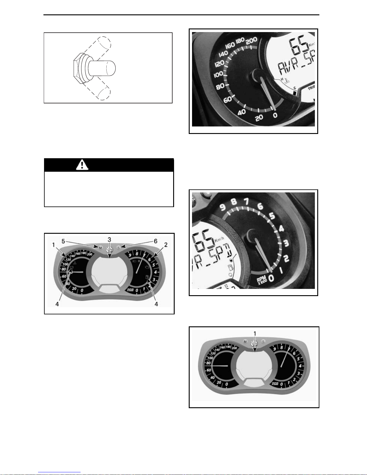
G) Average Speed
Records vehicle average speed since it
has been reset.
To display vehicle average speed, proceed as follows.
Press the MODE (M) button to select
display 1.
mmo2007-009-066_m
While display flashes, press SET (S)
button to select vehicle average speed
(AVR_SPD) mode.
34
______________
Page 37

CONTROLS, INSTRUMENTS AND EQUIPMENT
mmo2007-009-066_n
1. Vehicle average speed (AVR_SPD) mode
Press the MODE (M) button to co nfirm
selection or w ait 5 seconds.
mmo2007-009-066_o
Toreset, press the MODE (M) to select
mode.
mmo2007-009-066_m
While display flashes, press and hold
the SET (S) button within 5 seconds to
reset.
mmo2007-009-066_w
H) Instant Fuel Consumption
Calculates vehicle average fuel consumption while riding.
To display vehicle average fu el consumption, proceed as follows.
Press the MODE (M) button to select
display 1.
mmo2007-009-066_m
While display flashes, press SET (S)
button to select instant fuel consumption mode.
mmo2007-009-066_n
1. Instant fuel consumption mode
Press the MODE (M) button to co nfirm
selection or w ait 5 seconds.
_______________
35
Page 38

CONTROLS, INSTRUMENTS AND EQUIPMENT
mmo2007-009-066_o
I) Total Fuel Consumption
Records vehicle average fuel consumption since it has been reset.
To display vehicle to tal fuel consumption, proceed as follows.
Press the MODE (M) button to select
display.
mmo2007-009-066_m
While display fla sh es, press the SET
(S) button to select total fuel consumption (TC) mode.
mmo2007-009-066_n
1. Total fuel consumption (TC) mode
TC appears when the mode is selected.
mmo2008-003-021_a
TYPICAL
Press the MODE (M) button to co nfirm
selection or w ait 5 seconds.
mmo2007-009-066_o
To reset, set the t rip meter to TRIP B.
Refer to
TRIP METER “A” OR “B”
for
more details.
mmo2007-009-066_p
1. Trip meter (TRIP B) mode
Press and hold the SET (S) button to reset.
36
______________
Page 39

CONTROLS, INSTRUMENTS AND EQUIPMENT
mmo2007-009-066_w
J) Message Display
mmo2007-009-066_c
1. Message display
Refer to
PILOT LAMPS AND MES-
SAGES
in this section for details on
usual messages.
Refer to
MONITORING SYSTEM
for
details on malfunction.
K) Top RPM
Records engine top revolution per
minute (RPM) since it has been reset.
To display engine top revolution per
minute, proceed as follows:
1. Press the MODE (M) button to select display.
mmo2007-009-066_m
NOTE: Display will flash for approximately 5 seconds, then will return to
the previously selected mode if display
is not changed.
2. W h ile display flashes, press the SET
(S) button to scroll and select top
RPM (TOP_RPM ) mode.
mmo2007-009-066_n
1. Top RPM (TOP_RPM ) mode
3. P r ess the MODE (M) button to confirm selection or wait 5 seconds.
mmo2007-009-066_o
Toreset, press the MODE (M) to select
mode.
mmo2007-009-066_m
Press and hold the SET (S) button
within 5 seconds to reset.
_______________
37
Page 40

CONTROLS, INSTRUMENTS AND EQUIPMENT
mmo2007-009-066_w
L) Lap Record Mo de
With this mode, vehicle speed, engine
revolutions per minute (RPM) and a
preselected function in display 1 can
be recorded at the same time during a
period of time defined by the operator.
Also, a possibility of nine ( 9) different
sessions (laps) can be recorded for a
maximum total of 2-1/2 minutes.
mmo2007-009-066_h
LAP RECORD MODE
1. Lap record mode display
2. Sessions (laps)
3. Vehicle s peed
4. Engine revolution per minute (RPM)
5. Preselected function
To Activate Lap Record Mode:
1. Press the SET (S) button to select
the odometer mode in display 3.
2. Press and hold SET (S) button for 2
seconds to activate mode, REC will
be displayed to indicate that record
mode has been selected.
mmo2009-009-002_a
1. Record mode
2. Odometer
3. Press the SET (S) button to scroll between modes.
Available modes are: STOP, REC
(record) or PLAY.
To Record:
1. Select REC (record) mode.
mmo2008-007-003
RECORD MODE
2. Press the MODE (M) button to start
recording.
3. While recording, press the MODE
(M) button again each time you want
to record a new lap time (from 1 to 9
laps).
Press theSET(S)buttontostoprecording.
38
______________
Page 41

CONTROLS, INSTRUMENTS AND EQUIPMENT
mmo2009-009-003_a
RECORD MODE
1. Recording time
2. Lap/session
3. Selected mode
To record another session, press the
SET (S) button until REC (record) mode
appears in display. Repeat same procedure previously described to record.
To Review Recorded Data:
Select PLAY mode.
mmo2008-007-005_a
PLAY MODE
1. Press the MO DE (M) button to play
recorded data.
All recorded data (speedometer,
tachometer and the preselected mode
in display 1) will be displayed at the
same time.
2. Press the SET (S) button to stop
recorded lap OR press the MODE
(M)buttontoswitchtoanother
recorded lap.
NOTE: Pressing the SET (S) button will
stop time of the lap in progress, then
the display will show the recorded time
length of that lap and will switch automatically to the following recorded lap
after 5 seconds.
At the end of all recorded laps, STOP
will appear in display.
To review recorded data again, press
theSET(S)buttontoreturntoPLAY
mode. Repeat same procedure previously described to review.
To record other laps, press the SET (S)
buttontoswitchtoREC(record)mode.
Repeat same procedure previously described to record.
Press and hold SET (S) button for 5 seconds to exit the lap record mode, the
previously selected mode will be displayed.
M) Exhaust Gas Temperature
Displays real time exhaust gas temperature and records the maximum reading.
To display exhaust g a s temperature,
proceed as follows:
1. Press the MODE (M) button to select display.
mmo2007-009-066_m
NOTE: Display will flash for approximately 5 seconds, then will return to
the previously selected mode if display
is not changed.
2. While display flashes, press the
SET (S) button to scroll and select
exhaust gas temperature (EGTM)
mode.
_______________
39
Page 42

CONTROLS, INSTRUMENTS AND EQUIPMENT
mmo2008-007-006_a
EXHAUST GAS TEMPERATURE (EGTM)
MODE
1. Current temperature
2. Maximum temperature recorded
3. Press the MODE (M) button to confirm selection or wait 5 seconds.
mmo2007-009-066_o
To reset maximum temperature
recorded, press the MODE (M) to select mode.
mmo2007-009-066_m
Press and hold the SET (S) button
within 5 seconds to reset.
mmo2007-009-066_w
N) Throttle Position Display
Displays real time throttle open ing in
percentage from approximately 0 to
100%.
To display throttle position, proceed as
follows:
1. Press the MODE (M) button to select display.
mmo2007-009-066_m
NOTE: Display will flash for approximately 5 seconds, then will return to
the previously selected mode if display
is not changed.
2. W h ile display flashes, press the SET
(S) button to scroll and select throttle position (TPS) mode.
mmo2009-009-005
THROTTLE POSITION MODE
40
______________
Page 43

CONTROLS, INSTRUMENTS AND EQUIPMENT
3. P r ess the MODE (M) button to confirm selection or wait 5 seconds.
mmo2007-009-066_o
13) Front and Rear
Bumpers
To be used whenever snowmobile requires manual lifting.
CAUTION Use proper lifting
techniques, notably using your legs
force. Do not attempt to lift either
end of the vehicle if it is above your
limits. Use appropriate lifting device or have assistance to share lifting stress if possible.
mmo2008-003-016_a
FRONT
1. Front bumper
mmo2009-009-006_a
REAR
1. Rear bumper
NOTICE
Do not use skis to pull or
lift snowmobile.
14) Drive Belt Guard
Drive Belt Guard Removal
WARNING
NEVER operate engine:
– Without shields and belt guard
securely installed.
– With hood and/or side panels
opened or removed.
NEVER attempt to make adjustments t o moving parts while engine is running.
NOTE: Belt guard is purposely made
slightly oversize to maintain te nsion on
its pins and retainers preventing undue
noise and vibration. It is important that
this tension be maintained when reinstalling.
Remove the tether cord cap.
Open engine compartment LH side
panel, refer to
CONTROLS, INSTRU-
MENTS AND EQUIPMENT
.
Remove retaining pin.
_______________
41
Page 44

CONTROLS, INSTRUMENTS AND EQUIPMENT
mmo2008-007-016_a
1. Retaining pin
Lift rear portion of guard then release
from upper retaining pin.
Release guard from the front tabs by
pivoting the guard outwards.
Drive Belt Guard Installation
When reinstalling belt guard, position
its cutaway toward front of snowmobile.
Place the front LH slot of the guard
over the longest tab.
Pivottheguardinwardtoengagethe
shortest tab in the RH slot.
mmo2009-003-010_a
1. Tabs
Position the gro mmet o ver the retaining rod. It may be necessary to slightly
lifttheconsoletomakeroom.
mmo2009-003-011_a
1. Retaining rod
Position rear portion of belt guard over
retainer and secure it using retaining
pin.
mmo2008-007-016_a
1. Retaining pin
15) Spare Drive Belt Holder
A spare drive belt can be stored in
holder.
NOTE: Sp are drive belt is not supplied
with the snowmobile.
Properly install spare belt and secure
with Velcro strap a s shown.
NOTICE
To avoid damages to the
drive belt, ensure that belt does not
come in contact with tuned pipe
when installed in its support.
42
______________
Page 45

CONTROLS, INSTRUMENTS AND EQUIPMENT
fmo2012-003-056_a
WRONG INSTALLATION
1. Drive belt in contact with tuned pipe
fmo2012-003-057_a
INSTALLED CORRECTLY
1. Drive belt over bumper
2. Ensure there is no contact with tuned pipe
mmo2009--003-008_a
SECURE W ITH VELCRO STRAP
16) Hood
WARNING
Never operate engine with hood
removed from vehicle.
To open hood, release hood retaining
pins then slide hood towards the front
of the vehicle.
fmo2012-009-001
Step 1: Release retaining pins
Step 2: S lide hood towards the front
17) Side Panels
WARNING
Never operate engine with side
panels opened or removed from
vehicle.
To open a side panel, stretch and unhook the latches.
mmo2008-003-075_a
TYPICAL
1. Latches
_______________
43
Page 46

CONTROLS, INSTRUMENTS AND EQUIPMENT
To remove a side panel, open it then lift
it up. Free the lower hinge from its slot,
then free the upper hinge by lowering
the panel.
44
______________
Page 47

FUEL AND O IL
Recommended Fuel
NOTICE
This vehicle has no oil
pump, oil must be mixed with fuel.
Refer to
RECOMMENDED OIL
for
proper fuel/oil ratio.
Use premium unleaded gaso lin e available from most service stations or oxygenated fuel containinga maximum total of 10% of ethanol or methanol. Th e
gasoline used must have the following
recommended minimum octane rating.
NOTE: When the vehicle is used in ra cing condition, the use of oxygenated
fuel is prohibited. Contact racing authority for more details.
Outside North America
OCTANE RATING
600 RS
98 RON E5
NOTICE
Never experiment with
other fuels or fuel ratios. The use of
not recommen ded fuel can result i n
snowmobile performance deterioration and damage to critical parts in
the fuel system and engine components.
Fuel System Antifreeze
When using oxygenated fuel, additional gas line antifreeze or water absorbing additives are not required and
should be not used.
When using non-oxygenated fuel, we
highly recommend the use of isopropyl
base gas line antifreeze in a proportion
of 150 ml (5 U.S. oz) of gas line antifreeze added to 40 L (10 U.S. gal.) of
gas.
This precautionisinordertoreduce the
risk of frost buildup in carburetors or
other fuel system components which
may lead, in certain cases, to high fuel
consumptionorseveredamagetoengine.
NOTE: Use only methyl hydrate free
gas line antifreeze. When the vehicle
is used in racing condition, verify with
theracingauthoritytoknowwhich
quantity of gas line antifreeze is allowed to avoid disqualificatio n.
Vehicle Fueling Procedure
WARNING
– F uel is flammable and explosive
under certain conditions.
– Never use an open flame to
check fuel level.
– N ever smoke or allow flame or
spark in vicinity.
– Alwaysworkinawell-ventilated
area.
1. Stop engine.
WARNING
Always stop engine before refueling.
2. Ensure no one sits on vehicle while
refueling.
WARNING
Do not allow anyone seated on the
vehicle while fueling.
3. Unscrew slowly the fuel reservoir
cap counterclockwise to remove it.
_______________
45
Page 48

FUEL AND OIL
fmo2010-003-008
TYPICAL
1. Fuel tank cap
WARNING
If a differential pressure condition
is noticed (whistling sound heard
when l oosening fuel rese rvoir cap)
have vehicle inspected and/or repaired before further operation.
4. Insert the spout into the filler neck.
5. Pour fuel slowly so that air can escape from the tank and prevent fuel
flow back. Be careful not to spill
fuel.
6. Stop filling when the fuel reaches
the bottom of filler neck. Do not
overfill.
WARNING
Never top up the fuel tank before
placing the vehicle in a warm area.
As temperature increases, fuel expands and may overflow.
7. Fully tighten fuel reservoircapclockwise.
WARNING
Always wipe off any fuel spillage
from the vehicle.
NOTE: Do not sit or lean on seat when
fuel tank cap is not properly installed.
Recommended Oil
This vehicle has no oil pump, oil must
bemixedwithfuelattheratioof33:1
in a jerry can then, be poured in the fuel
tank.
Refer to
PREMIX FUEL/OIL RATIO
table below as a guideline to properly
premix oil with fuel.
NOTICE
Never experiment with
other fuel/oil ratios. Use only oil that
can flow at -40°C (-40 °F).
Use only two-stroke engine injection
oil, sold by authorized Lynx dealers.
2-STROKE ENGINE INJECTION OIL
XPS SYNTHETIC
2-STROKE OIL (P/N 619
590 106)
600 RS
XPS SYNTHETIC
BLEND 2-ST R OKE OIL
(P/N 619 590 103)
NOTICE
(1) The engine of this
snowmobile has been developed
and validated using the XPS™ Synthetic Blend 2 -stro ke oil and XPS
synthetic 2-stroke oil. BRP strongly
recommends the use of either lubricant at all times. Damages caused
by oil which is not suitable for the
engine will not be covered by the
BRP limited warran ty.
Premix Fuel/Oil Ratio
NOTE: The recommended fuel/oil ratio is 33:1.
Following are examples with this
fuel/oil ratio.
FUEL/OIL RATIO
946 ml (1 qt (U.S. liq.)) oil bottle : 31.2 L
(8.3 U.S. gal.) of fuel
1 L (1.1 qt (U.S. liq.)) oil bottle : 33 L
(8.7 U.S. gal.) of fuel
46
______________
Page 49

BREAK-IN PERIOD
Operation During Break-In
A break-in period o f 10 operating hours
or 500 km (300 mi) is required for the
vehicle.
After the break-in period, the vehicle
should be inspected by an authorized
Lynx dealer. Refer to
MAINTENANCE
section.
Engine
During the break-in period:
– Avoid prolonged full throttle opera-
tion.
– Avoid sustained accelerations.
– Avoid prolonged cruising speeds.
– Avoid engine overheatin g.
However, brief accelerations and
speed variations contribute to a good
break-in.
During the first few hours of break-in,
the engine management system controls some engine parameters which
will slightly reduce the engine performance.
Drive Belt
A new drive belt requires a break in period of 50 km (30 mi).
During the break-in period:
– Avoid strong acceleration and decel-
eration.
– Avoid pulling a load.
– Avoid high speed cruising.
_______________
47
Page 50

BASIC PROCEDURES
Engine Starting Procedure
Procedure
1. Apply parking brak e.
2. Recheck throttle control lever operation.
3. Putyourhelmeton.
4. En sure that the tet her cord cap is in
position and that the cord a ttached
to your clothing eyelet.
5. En sure that the em ergency engine
stop switch is in the ON position.
6. To prime, activate button until a
pumping resistance is felt. From
this point, pump 2 or 3 times to inject fuel in intake m anifold. After
priming, ensure that primer button
is pushed back.
NOTE: In very cold temperature, it is
recommended to rotate primer button
3 - 4 turns prior to pull it. This will eliminate the possibility of sticking.
NOTE: Priming is not necessary when
engine is warm.
7. Gra b manual starter handle, pull
handle slowly until a resistance is
felt,thenholdhandlefirmlyandpull
vigorously to start engine.
8. Release parking brake.
NOTE: For an initial cold start, do not
release parking brake. Perform the
VEHICLE WARM-UP
procedure as ex-
plained below.
Vehicle Warm-Up
Before every ride, vehicle has to be
warmed up as follows .
1. Start engine as explained in
ENGINE
STARTING PROCEDURE
above.
2. Allow engine to warm up one or two
minutes at idle speed.
NOTE: It is not recommended to let
engine running at idle speed for more
than 10 minutes.
3. Disengage parking brake.
4. Apply throttle until drive pulley engages. Drive at low speed the first
two or three minutes.
NOTICE
If vehicle does not move
when throttle is applied, remove
tether cord cap, then do the following.
– Check if skis are stuck on the
ground. Lift one ski at a time by
the handle, then put it down.
– Check if track is stuck on the
ground. Lift rear of snowmobile
enough to clear track from the
ground, then drop.
– Check rear suspension for hard
snow or ice accumulation that
could interfere with track rotation. Clean the area.
CAUTION Beware of in ju ries
by using proper lifting techniques,
notably using your legs force. D o
not attempt to lift the rear of vehicle
if it is above your limits.
WARNING
Make sure tether cord cap is away
from post before standing in front
the vehicle, getting close to the
track or rear suspension components.
Shutting Off the En gine
Release throttle lever and wait until engine has returned to idle speed.
Shut off the engine using either emergency engine stop switch or pulling off
the tether cord cap.
WARNING
Always remove the tether cord cap
when vehicle is not in operation in
order to prevent accidental engine
starting or to avoid unauthorized
use by children or others or theft.
48
______________
Page 51

RIDING CONDITIONS AND YOUR SNOWMOBILE
Altitude
NOTICE
This vehicle is factory calibrated for a sea level usage ONLY,
below 600 m (2000 ft).
Temperature
All vehicles have been calibrated for
-20°C (-4°F). They can be operated at
warmer winter temperatures without
risk of problems.
NOTICE
For colder temperatures
than -20°C (-4°F), carburetor(s) must
be recalibrated to avoid engine damage. Refer to an authorized Lynx
dealer.
Hard Packed Snow
This snowmobile's track has a lug profile of 44 mm (1.732 in) and BRP does
not recommend to ride it at hi gh
speed on a trail, hard packed snow
or ice.
Intheeventthatyouhavetorideon
such surfaces, reduce your speed
and minimize the travel distance.
NOTICE
Running that type of track
at high speeds on a trail, on hard
packed surfaces or ice puts more
stress on the lugs, causing heat. To
avoid potential premature degradation or damage to the track, reduce
your speed, and minimize the distance you ride on those surfaces.
_______________
49
Page 52

SPECIAL P RO CED URES
Towing Another
Snowmobile
If a snowmobile is disabled and must
be towed use a rigid tow bar. Remove
the drive belt from the disabled snowmobile, refer to
DRIVE BELT
in the
MAINTENANCE PROCEDU RE
section
and tow at moderate speed.
NOTICE
Always remove the driv e
belt of the snowmobile that is to be
towed to prevent damage to its belt
and drive system.
In an emergency situation only, if a rigid
tow bar is not available, a rope can be
used provided you proceed with extra
caution. In some areas, it may be illegal to do so. Check with state or local
authorities.
Remove the drive belt, attach the ro pe
to the ski legs (spindles), have someone sit on the towed sn owmobile to activate the brake, and tow at low speed.
NOTICE
In order to prevent damage to the steering system, never
attach the tow rope to the ski loops
(handles).
WARNING
Never ride at high speed when
towing a disabled snowmobile.
Proceed slowly with extra caution.
Emergency Starting
Procedure
The engine can be started with an
emergency starter rope.
Remove drive belt guard.
WARNING
Do not wind starting rope around
your hand. Hold rope by the handle only. Do not start the snowmobile by the drive pulley unless it is
atrueemergencysituation. Have
the snowmobile repaired as soon
as possible.
mmo2008-005-008_a
Attach one end of emergency rope to
rewind handle.
NOTE: The spark plug socket can be
used as an emergency handle.
mmo2008-005-007
Attach the other end of emergency
rope to a starter clip.
50
______________
Page 53

SPECIAL PROCEDURES
mmo2008-005-009
Hook up clip on drive pulley.
mmo2008-005-012_a
1. Clip installation location
Wind the rope tightly around drive pulley. When pulled, pulley must rotate
counterclockwise.
mmo2008-005-014_a
Pull the rope using a sharp, crisp pull so
the rope comes free of the drive pulley.
Start engine as per usual manual starting.
WARNING
When starting the snowmobile
in an emergency situation, using
drive pulley, do not reinstall the
drive belt guard and return slowly
to have snowmobile repaired.
_______________
51
Page 54

TUNE YOUR RIDE
Snowmobile handling and comfort depends on suspension adjus tments.
WARNING
Suspension adjustment could affect vehicle handling. Always take
time to familiarize yourself with
the vehicle's behavior after any
suspension adjustment have been
made. Always adjust LH and RH
suspension components to the
same setting.
Choice of suspension adjustments
vary with carrying load, operator's
weight, personal preference, riding
speed and field condition.
NOTE: Some adjustments may not apply to your snowmob ile.
WARNING
Before proceeding with any suspension adjustment, remember:
– P ark in a safe place.
– Remove the tether cord cap.
– Use appropriate lifting device or
have assistance to share lifting
stress. If a lifting device is not
used, use proper lifting techniques, notably using your legs
force.
– Do not attempt to lift the front or
rear of ve hicle if it is above your
limits.
– Support front of vehicle off the
ground with a suitable device
before adjusting suspension.
– Support rear of vehicle off the
ground with a wide-base snowmobile stand with a rear deflector panel.
– Make sure support device is sta-
ble and secure.
The best way to set up the suspension is to customize each adjustment
one at a time. Various adjustments
are interrelated. It may b e necessary
to readjust center spring after adjusting front springs for instance. Test run
the snowmobile under the same conditions; trail, speed, snow, operator
riding position, etc. Proceed methodically until you are satisfied.
Following are guidelines to fine-tune
suspension.
Rear Suspension
Adjustments
fmo2012-005-500_a
1. Rear springs and shock absorber
2. Center spring and shock absorber
3. Stopper strap
NOTICE
Whenever adjusting rear
suspension, check track tension and
adjust if necessary.
Rear Spring
Rear spring preloa d has an effect o n
comfort, ride height and load compensation.
Also, adjusting rear spring preload
shifts more or less weight to the snowmobile front end. As a result, more or
less we ig ht is applied t o the skis. This
has an effect on performance in deep
snow, steering effort and handling.
Slight suspension bottoming occurring
under the worst riding conditions indicates a good choice of spring preload.
52
______________
Page 55

TUNE YOUR RIDE
ACTION RESULT
Firmer rear suspension
Higher rear end
More bump absorption
capability
Increasing
preload
Heavier steering
Softerrearsuspension
Lower rear end
Less bump absorption
capability
Lighter steering
Decreasing
preload
Better performance and
handling in deep snow
Refer to the following to determine if
preload is c orrect.
C
B
A
mmo2006-003-022_a
TYPICAL — PROPER ADJUSTMENT
A. Suspension fully extended
B. Suspension has collapsed with operator an d
load added
C. Distance between dimension “A” and “B”,
see table below
”C” WHAT TO DO
50 mm to 75 mm
(2 in to 3 in)
No adjustment
required
More than
75 mm (3 in)
Adjusted too soft,
increase preload
Less than
50 mm (2 in)
Adjusted too firm,
decrease preload
NOTE: If the specification is unattainable with the original springs, see an
authorized Lynx dealer for other available springs.
fmo2012-005-502_a
1. Rear spring
2. Adjust spring preload
Center Spring
Center spring preload has an effect on
steering effort, handling and bump absorption.
Also, since center spring preload adjustment puts more or les s pressure
on the front of the track, it has an effect on the performance in deep snow.
ACTION RESULT
Lighter steering
More bump absorption
capability
Better deep snow starts
Increasing
preload
Better deep snow
performance and handling
Heavier steering
Less bump absorption
capability
Decreasing
preload
Better trail handling
_______________
53
Page 56

TUNE YOUR RIDE
mmo2010-003-027_a
TYPICAL- RING TYPE
1. Decrease preload
2. Increase preload
3. Spring preload adjustment ring
Stopper Strap
Stopper strap length has an effect on
the amount of weight the center spring
has to carry especially during acceleration, therefore on the front end uplift.
Stopper strap length also has an effect
on center spring travel.
NOTICE
Whenever stopper strap
length is changed, track tension
must be checked.
54
______________
Page 57

TUNE YOUR RIDE
ACTION RESULT
Lighter ski pressure under
acceleration
More center spring travel
Increasing
stopper
strap
length
More bump absorption
capability
Heavier ski pressure
under acceleration
Less center spring travel
Decreasing
stopper
strap
length
Less bump absorption
capability
fmo2012-005-501_a
TYPICAL
1. Position 1(factory setting)
2. Position 2
3. Position 3
4. Position 4
NOTE: Decreasing the stopper strap
length may reduce comfort. Always
install s topper strap bolt as close as
possible to the lower shaft.
When ope rating the snowmobile in
deep snow, it may be necessary to vary
stopper strap length and/or riding position, to change the angle at which the
track rides on the snow. Operator's familiarity with the various adjustme n ts
as well as snow conditions will dictate
the most efficient combination.
Generally, a longer stopper strap setting gives better performance in deep
snow on a flat landscape.
Rear Shock
Low Speed Compression Damping
Low speed compression damping c ontrols how the shock absorber reacts to
a low suspension velocity (slow compression strokes, in most cases when
riding at lower speeds).
ACTION
RESULT ON BIG
BUMPS
Increasing
low speed
compression
damping force
Firmer
compression
damping (slo w
compression)
Decreasing
low speed
compression
damping force
Softer
compression
damping (slo w
compression)
To adjust, turn clockwise to increase
damping force and counterclockwise
to decrease damping force.
fmo2012-005-504_b
1. Rear shock absorber
2. Low speed compression damping adjuster
(knob or slot)
High Speed Compression Damping
High speed compression damping
controls how the shock absorber reacts to a high suspension velocity
(quick com pression strokes, in most
cases w hen riding at higher speeds).
_______________
55
Page 58

TUNE YOUR RIDE
ACTION
RESULT ON
SMALL BUMPS
Increasing
high speed
compression
damping force
Firmer
compression
damping (fast
compression)
Decreasing
high speed
compression
damping force
Softer
compression
damping (fast
compression)
To adjust, turn clockwise to increase
damping force and counterclockwise
to decrease damping force.
fmo2012-005-504_a
1. Rear shock absorber
2. High speed compression damping adjuster
(hexagonal)
Center Shock
Low Speed Compression Damping
Low speed compression damping controls how the shock absorber reacts to
a low suspension velocity (slow compression strokes, in most cases when
riding at lower speeds).
ACTION
RESULT ON BIG
BUMPS
Increasing
low speed
compression
damping force
Firmer
compression
damping (slo w
compression)
Decreasing
low speed
compression
damping force
Softer
compression
damping (slo w
compression)
To adjust, turn clockwise to increase
damping force and counterclockwise
to decrease damping force.
fmo2012-005-505_a
1. Center shock absorber
2. Low speed compression damping adjuster
(knob or slot)
High Speed Compression Damping
High speed compression damping
controls how the shock absorber reacts to a high suspension velocity
(quick com pression strokes, in most
cases w hen riding at higher speeds).
ACTION
RESULT ON
SMALL BUMPS
Increasing
high speed
compression
damping force
Firmer
compression
damping (fast
compression)
Decreasing
high speed
compression
damping force
Softer
compression
damping (fast
compression)
56
______________
Page 59

TUNE YOUR RIDE
To adjust, turn clockwise to increase
damping force and counterclockwise
to decrease damping force.
fmo2012-005-505_a
1. Center shock absorber
2. High speed compression damping adjuster
(hexagonal)
Front Suspension
Adjustments
Front Springs
Front spring preload has an effect on
front suspension firmness.
Front spring preload also has an effect
on the steering behavior.
ACTION RESULT
Firmer front suspension
Higher front end
More precise steering
Increasing
preload
More bump absorption
capability
Softer front suspension
Lower front end
Lighter steering
Decreasing
preload
Less bump absorption
capability
mmo2010-003-027_a
TYPICAL- RING TYPE
1. Decrease preload
2. Increase preload
3. Spring preload adjustment ring
NOTICE
Make sure that both front
springs are still pre-loaded when
front of vehicle is off the ground.
Front Shock Absorbers
Low Speed Compression Damping
Low speed compression damping c ontrols how the shock absorber reacts to
a low suspension velocity (slow compression strokes, in most cases when
riding at lower speeds).
ACTION RESULT
Increasing
low speed
compression
damping force
Firmer
compression
damping (slo w
compression)
Decreasing
low speed
compression
damping force
Softer
compression
damping (slo w
compression)
To adjust, turn clockwise to increase
damping force and counterclockwise
to decrease damping force.
_______________
57
Page 60

TUNE YOUR RIDE
mmo2010-003-020_a
1. Low speed compression damping adjuster
(slot or knob)
High Speed Compression Damping
High speed compression damping
controls how the shock absorber reacts to a high suspension velocity
(quick compression strokes, in most
cases w hen riding at higher speeds).
ACTION RESULT
Increasing
high speed
compression
damping force
Firmer
compression
damping (fast
compression)
Decreasing
high speed
compression
damping force
Softer
compression
damping (fast
compression)
To adjust, turn clockwise to increase
damping force and counterclockwise
to decrease damping force.
mmo2010-003-020_b
1. High speed compression damping adjuster
(hexagonal)
Rebound Damping
Rebound damping controls how the
shock absorber restrains the extension stroke.
ACTION RESULT
Increasing
rebound damping
force
Firmer rebound
damping
(extension stroke)
Decreasing
rebound damping
force
Softer rebound
damping
(extension stroke)
NOTE: In repetitive short small bumps
(ripple), it is recommen ded to use a
lower rebound damping setting.
mmo2010-003-020_c
1. Rebound adjuster (knob or slot)
58
______________
Page 61

TUNE YOUR RIDE
Adjustment Tips According to Vehicle Behavior
PROBLEM CORRECTIVE MEASURES
Front suspension darting
Check ski alignment.
– Reduce front suspension spring preload.
– Increase cen ter sprin g preload.
– Reduce rear spring preload.
Steering feels too heavy at steady
speeds
– Reduce front suspension spring preload.
– Increase cen ter sprin g preload.
Steering feels too heavy during
acceleration
– Reduce rear spring preload
– Lengthen limiter strap.
Too much ski lift during cornering
or acceleration
– Sho rten limiter strap.
– Increase rear spring preload.
Rear of snowmobile seems too
stiff
– Reduce rear spring preload.
– Reduce compression damping adjustment
(if applicable)
Rear of snowmobile seems too
soft
Increase rear spring preload.
Rear suspension is fre qu entl y
bottoming
– Increase re ar sprin g preload.
– Increase cen ter spring preload.
– Leng then limiter strap.
– Increase compression damping adjustment
(if applicable)
Snowmobile seems to pivot
around its center
– Reduce center spring preload.
– Increase re ar sprin g preload.
– Increase front suspension spring preload.
– Shorten limiter strap.
Track spins too much at start
– Leng then limiter strap.
_______________
59
Page 62

VEHICLE TRANSPORTATION
Make sure that fuel tank cap is properly
installed.
Tilt bed trailers ca n eas ily be equipped
with a winch mechanism to afford maximum safety in loading.
WARNING
NEVER drive your snowmobile
onto a tilt bed trailer or any other
kind of trailer or vehicle. As easy
to do as it may seem, many serious accidents have resulted from
driving up and over a trailer.
Anchor your vehicle securely, front and
rear, even on short hauls. Be certain
all equipment is securely fastened.
Cover your snowmobile when trailering to prevent road grime from c ausing
damage.
Be certain your trailer meets state or
provincial requirements. Ensure the
hitch and safety chains are secure and
the brake, turn indicators and clearance lights all function.
60
______________
Page 63

MAINTENANCE
INFORMATION
_______________
61
Page 64

BREAK-IN INSPECTION
After the first 10 hours or 500 km of operation, whichever comes first, your vehicle
have to be inspected by an authorized Lynx dealer. The break-in inspection is very
important and must not be neglected.
NOTE: The break-in inspection is at the expense of the vehicle owner.
BREAK-IN INSPECTION (2-STROKE)
Inspect engine motor mounts
Inspect exhaust system and check for leaks
Tighten exhaust manifold screws to specified torque
Check coolant level
Inspect fuel lines and connections
Inspect throttle cable
Inspect oil injection pump adjustment (All except E-TEC)
Inspect drive belt
Visually inspect drive pulley
Tighten drive pulley retaining screw to specified torque
Inspect driven pulley
Inspect spark plugs (All except E-TEC)
Adjust and align track
Change chaincase / gearbox oil
Retorque gearbox cover screws both sides of speedometer sen sor con nector to 10Nm
(Only XU Models)
Adjust drive chain (Not for models equipped w ith gearbox)
Check brake fluid level
Inspect brake hose, pads and disk
Inspect steering mechanism
Inspect skis and runners
Tighten frame pyramid rod screws to specified torque
Inspect front suspension
Inspect rear suspension and slider shoes
Lubricate front and rear suspension
62
______________
Page 65

PERIODIC MAINTENANCE CHART
WARNING
It is recommended that the assistance of an authorized LYNX dealer be
periodically obtained on other components/systems not covered in this
guide. Unless otherwise specified, engine must be cold and not running.
Remove the tether cord cap (DESS key) before performing any maintenance or adjustment, unless otherwise specified. Vehicle must be parked
in a safe place, away from the trail.
WARNING
Observe WARNINGS and CAUTIONS mentioned throughout this guide
which are relevant to the item being checked. When component conditions
seem less than satisfactory, replace with genuine BRP parts or approved
equivalents.
Some items may not apply to your particular model. Refer to
MAINTENANCE
in
SHOP MANUAL
for more details.
_______________
63
Page 66

MAINTENANCE SCHEDULE (2-STROKE)
NOTE: The maintenance schedule does not exempt the pre-ride inspection.
EVERY 1 500 KM
T/A shocks oil change / service. First at 1500 km, then every 3000 km or once a year.
Models with chaincase: Adjust drive chain
Models with gearbox: Check oil level
EVERY 3 000 KM OR 1 YEAR
(WHICHEVER COMES FIRST)
Inspect heat shields
Inspect engine motor mounts
Inspect exhaust system and check for leaks
Inspect cooling system cap, hoses and clamps and check for leaks
Replace spark plugs (All except of E-TEC)
Clean RAVE valves
Inspect RAVE valves solenoid
Adjust engine stopper
Visually inspect and clean drive pulley
Tighten drive pulley retaining screw to specified torque
Clean driven pulley
Adjust and align track
Inspect brake hose, pads and disk
Inspect steering mechanism
Inspect front suspension
Inspect rear susp ensi on and stopper strap. P PS Suspen sion: Replace stopper strap.
Lubricate front and rear suspension whenever the vehicle is used in wet conditions
(wet snow, rain, puddles)
Lubricate QRS axle gearbox end. (XU models)
64
______________
Page 67

MAINTENANCE SCHED ULE (2-STROKE)
EVERY6000KMOR2YEARS
(WHICHEVER COMES FIRST)
Inspect fuel pump strainer and replace if necessary
Replace spark plugs (800 E-TEC only)
Replace brake fluid
Inspect throttle cable
EVERY 10 000 KM OR 3 YEARS
(WHICHEVER COMES FIRST)
Replace oil filter (E-TEC: Inspect oil pump strainer and clean if needed)
Replace spark plugs (600 E-TEC only)
EVERY 5 YEARS
Replace in-line fuel filter
Replace engine coolant
_______________
65
Page 68

PRESEASON PREPARATION
PRESEASON PREPARATION (2-STROKE)
Inspect engine motor mounts
Check e xhaust system condition and check for leaks
Tighten exhaust manifold screws or nuts to specified torque
Replace spark plugs. (All except E-TEC)
Inspect cooling system cap, hoses and clamps
Check coolant density
Inspect crankshaft PTO seal
Inspect fuel lines and connections
Clean and inspect throttle body
Inspect throttle cable
Inspect drive belt (adjust at every drive belt replacement)
Clean and visually inspect drive pulley
Clean and inspect driven pulley
Inspect, adjust and align track
Adjust drive chain (Not for models equipped w ith gearbox)
Change chaincase / gearbox oil
Check brake fluid level
Inspect brake hose, pads and disk
Inspect steering mechanism
Inspect skis and runners
Inspect front suspension
Inspect rear suspension stopper strap
Charge battery (if so equipped)
Adjust headlight beam aiming
66
______________
Page 69

STORAGE
During summer, or when a snowmobile is not in use for more than three months,
proper storage is a necessity.
STORAGE
Clean the vehicle
Add fuel stabilizer to fuel following the product manufacturer re commendations
Run the engine after adding the product to the fuel
2-Stroke models: Lubricate engine. See owne rs manual for instruction.
Lubricate brake lever pivot
Inspect and lubricate rear suspension
Charge battery monthly to keep it fully charge during storage
Block muffler with rags
Lift rear of vehicle until track is clear of the ground. Do not release track tension
Lubricate front and rear suspension
_______________
67
Page 70

MAINTENANCE PROCEDURES
This sectio n includes instructions for
basic maintenance procedures. If you
have the necessary mechanical skills
and the required tools, you can perform these pr ocedures. If not, see
your authorized Lynx dealer.
Other important items in the maintenance schedule that are more difficult
and require special tools are best performed by your authorized Lynx dealer.
WARNING
Turn off the engine, remove tether
cord cap and follow these main t enance procedures whe n performing maintenance. If you do not
follow proper maintenance procedures you can be injured by hot
parts, moving parts, electricity,
chemicals or other hazards.
WARNING
Should removal of a lockingdevice
(e.g. lock tabs, self-locking fasteners, etc.) be required when undergoing disassembly/assembly,
always replace with a new one.
Throttle Position Sensor
(TPS)
Throttle Position Sensor Reset
To reset TPS, proceed as follow s:
1. Refer to
CONTROLS, INSTRU-
MENTS AND EQUIPM EN T
and
open the RH side panel.
2. Remove the 6-pin vehicle connector
from its protective cap on the RH
side.
3. Connect the T-HARNESS (P/N 529
035 869) on the 6-pin connector.
4. Connect the T-harness to a 12 V battery using the 12 V BATTERY SUPPLY CABLE (P/N 529 035 997).
NOTICE
Respect battery polarity.
Install the RED probe on the positive
battery post, then the BLACK probe
on the negative battery post.
mmo2009-009-012_a
1. 6-pin connector
2. T-harness
3. 12 V battery supply cable
5. Fully depress throttle lever (wide
open position) and hold.
6. Depress the pre-heat switch for 5
seconds until beeper sounds.
7. Release throttle and pre-heat
switch.
8. Unplug battery and cables, close
side panel.
Air Filter
Air Filter Verification
Ensure that air intake filter is properly
installed, clean and in good condition.
68
______________
Page 71

MAINTENANCE PROCEDURES
fmo2012-009-013
TYPICAL
1. Air filter
Ifthefilterhastobecleanedorreplaced, see an authorized Lynx dealer.
Engine Coolant
WARNING
Never open radiator cap when engine is hot.
Engine Coolant level
Check coolant level at room temperature. Liquid should be at cold level line
(engine cold) of coolant tank.
NOTE: W h en checking level a t low
temperature it may be slightly lower
then the mark.
mmo2007-009-010_a
TYPICAL
1. Coolant tank
2. COLD LEVEL line
If coolant is low, remove the coolant
tank cap and add the recommended
engine coolant.
WARNING
Do not open coolant tank cap when
engine is hot.
Recommended Engine Coolant
Always use ethylene-glycol antifreeze
containing corrosion inhibitors specifically for internal combustion aluminum
engines.
Cooling system must be filled with
BRP PREMIXED COOLANT (P/N 219
700 362) or with distilled water and antifreeze solution (50% distilled water,
50% antifreeze).
Exhaust System
Exhaust System Verification
The muffler tail pipe should be centered with the exit hole in the bottom
pan. Exhaust system must be free of
rust or leaks. Make sure that all parts
are securely in place.
Check retaining springs condition and
replace if necessary.
The exhaust system is desig ne d to reduce noise and to improve the total
performance of the engine. Modification may be in vio latio n of local laws.
NOTICE
If any exhaust system
component is removed, modified
or damaged, severe engine damage
may result.
Spark Plugs
Spark Plug Removal
1. Open LH side panel, refer to
CONTROLS, INSTRUMENTS AND
EQUIPMENT
.
2. Remove belt guard, refer to
DRIVE
BELT GUARD REMOVAL
.
3. C are fully remove spark plug wire
cap with a twisting and pulling motion.
_______________
69
Page 72

MAINTENANCE PROCEDURES
4. Using a 19 mm spark plug socket,
unscrew spark plug a few turns
without removing it.
5. Cl ean vicinity of spark plugs.
NOTICE
Engine damage can occur
if grime particles enter into the combustion chambe r.
6. Remove spark plug.
Spark Plug Installation
1. Measure the spark plug gap.
NOTE: The gap is not adjustable. If
gap is incorrect, replace spark plugs.
NOTICE
Do not attempt to adjust
gap on these spark plugs.
SPARK PLUG GAP
0.45 mm ± 0.05 mm (.018 in ± .002 in)
2. Apply LOCTITE 767 (ANTISEIZE
LUBRICANT) (P/N 293 800 070) on
spark plug threads.
3. Screw each spark plug into cylinder
head by hand until it bottoms.
4. Perform the final tightening using a
torque wrench and a proper socket.
Torque to specification
TORQUE
Spark plug
27 N•m ± 2 N•m
(20lbf•ft ±1lbf•ft)
5. Connect spark plug wires.
Engine Stopper
Engine Stopper Adjustment
The engine stopper is located on the
LH front engine support, in front of the
drive pulley.
1. Remove the tether cord cap.
2. Rem o ve the LH side panel, refer to
CONTROLS, INSTRUMENTS AND
EQUIPMENT
.
3. Remove drive belt guard, refer to
DRIVE BELT GUARD REMOVAL
in
CONTROLS, INSTRUMENTS AND
EQUIPMENT
.
4. Loosen the three bolts retaining the
engine stopper to the engine support without removing them.
mmo2009-003-013_a
1. Engine stopper
2. Engine stopper screws
3. Drive pulley
5. Apply a d ownward pressure on the
engine stopper with your fingers
while tightening the screws just
enough to obtain contact between
the screw heads and the surface of
the stopper.
6. Torque screws to specification.
TORQUE
Engine
stopper
screw
10 N•m ± 2 N•m
(89 lbf•in ±18lbf•in)
NOTICE
Serious pulley damage
can occur if the engine stopper and
its screws are not properly installed.
Brake Fluid
Recommen ded Fluid
Use only DOT 4 brake fluid from a
sealed container. An opened container
may b e contaminated or may have absorbed moisture from the air.
70
______________
Page 73

MAINTENANCE PROCEDURES
WARNING
To avoid serious damage to the
braking system, do not use fluids
other than the recommended one,
nor mix different fluids for topping
up.
NOTICE
Brake fluid can damage
painted and plastic parts. Handle
with care. Rinse thoroughly in case
of spillage.
Brake Fluid Level
NOTICE
Vehicle must be on a level
surface before checking any fluid
levels.
Checkbrakefluid(DOT4)inreservoir
for proper level. Add fluid (DOT 4) as
required.
mmo2008-008-018_a
1. Minimum mark
2. Maximum mark
3. Operating range
WARNING
Avoidgetting brake fluid on skin or
eyes - it may cause severe burns.
In case of contact with skin, wash
thoroughly. In case of contact with
the eyes, immediately rinse with
plenty of water for at least 10 minutes and then consult a doctor immediately.
Chaincase Oil
Recommended Chaincase Oil
Use XPS SYNTHETIC CHAINCASE OIL
(P/N 413 803 300).
NOTICE
Use only the recommended type oil when servicing.
Do not m ix synthetic oil with other
types of oil.
Chaincase Oil Level
With the vehicle on a level surface,
check the oil level by removing the
magnetic check plug on the left side of
chaincase.
Oil level must reach the threaded
hole's lower edge.
mmr2008-047-002_a
1. Magnetic check plug
NOTE: It is normal to find metallic particles stuck to magnetic check plug. If
bigger pieces of metal are found, remove the chaincase cover and inspect
thechaincaseparts.
Remove metal particlesfrommagnetic
check plug.
To add oil, remove the filler cap on
chaincase cover.
_______________
71
Page 74

MAINTENANCE PROCEDURES
mmo2009-003-009_a
1. Filler cap
Pour recommended oil in chaincase
by the filler hole until oil comes out by
the magnetic check plug hole. Reinstall magnetic check plug and torque
to specification.
TORQUE
Magnetic
check plug
6N•m ± 1N•m
(53 lbf•in ±9lbf•in)
Drive Belt
Drive Belt Inspection
Inspect belt for cracks, fraying or abnormal wear (uneven wear, wear
on one side, missing cogs, cracked
fabric). If abnormal wear is noted,
probablecausecouldbeexcessive
RPM with frozen track, fast starts
without warm-up period, burred or
rusty sheav e, oil on belt or distorted
spare belt. Contact an authorized Lynx
dealer.
Drive Belt Replacement
Drive Belt Removal
1. Remove tether cord cap.
Open LH side panel, refer to
CONTROLS, INSTRUMENTS AND EQUIPMENT
.
2. Remove belt guard, refer to
BELT
GUARD REMOVAL
.
3. Insert the d rive belt installer/remover provided in the tool box in
the threaded hole on the adjuster
hub.
A33B0SA
DRIVE BELT INSTALLER/REMOVER TOOL
A33D1AA
4. O p en the driven pulley by screwing
the tool in.
5. Remove the belt by slipping it over
the top of the driven pulley, then
over the drive pulley.
Drive Belt Installation
The drive belt deflection must be
checked every time a new drive belt
is installed and should be rechecked
after 50 km (30 mi). Refer to
DRIVE
BELT ADJUSTMENT
below.
NOTE: T h e maximum drive belt life
span is obtained when the arrow on
the drive belt is directed toward the
front of the vehicle. This will ensure
that correct direction of rotation is respected.
72
______________
Page 75

MAINTENANCE PROCEDURES
mmo2008-003-045_a
1. Arrow pointing the front of vehicle
1. If necessary, open the driven pulley, refer to
DRIVE BELT REMOVAL
above.
2. Set drive be lt in the drive pulley then
in the driven pulley starting from the
bottom.
NOTICE
Do not force or use tools
to pry the belt into place, as this
could cut or break the cords in the
belt.
mbl2008-010-536
3. Unscrew and remove the drive belt
installer/remover tool.
4. Rotate the driven pulley several
times to properly set the belt between the sheaves.
5. Install belt guard, refer to
DRIVE
BELT GUARD INSTALLATION
.
6. Close side panel, refer to
CONTROLS, INSTRUMENTS AND
EQUIPMENT
.
Drive Belt Adjustment
Drive belt adjustment must be performed every time a new belt is installed.
To adjust the drive belt, proceed as follows:
1. Remove the tether cord cap.
2. Open LH side panel, refer to
CONTROLS, INSTRUMENTS AND
EQUIPMENT
.
3. Remove belt guard, refer to
DRIVE
BELT GUARD REMOVAL
.
4. Keep the set screw from turning
usinga1/8inchAllenwrenchand
loosen the lock nut using a 7/16 in
open wrench.
5. Turn the set screw 1/4 turn at a time
then rotate the driven pulley to properly set the belt between the pulley
sheaves. Measure belt deflection
using a straight edge and the TENSIOMETER (P/N 414 348 200) as
explained below.
414348200
6. Repeat until the right belt deflection
is reached.
NOTE: Turn the set screw clockwise
to increase the distance between the
sheaves and counterclockwise to decrease the distance.
7. Tighten the lock nut after the belt adjustment has been made.
A32D34A
_______________
73
Page 76

MAINTENANCE PROCEDURES
Belt Deflection Measurement
1. Set deflection between 27 mm
(1.06 in) and 37 mm (1.46 in) using
bottom O-ring.
mmr2009-133-003_b
DEFLECTION SETTING
1. Bottom O -ring
2. Place upper O-ring to 0 kgf (0 lbf).
3. Position a straight edge ruler on the
drive belt.
4. Position the tensiometer on drive
belt, halfway between pulleys.
5. Push the tensiometer downwards
until bottom O-ring (deflection) be
aligned with the inner edge of the
straight ruler.
6. Read load recorded by the upper
O-ring on the tensiometer.
mmr2009-133-003_a
LOAD READING
1. Upper O-ring
7. Load reading must be as per the following table.
DRIVEBELTADJUSTMENT
SPECIFICATION
Belt deflection
setting
27 mm to 37 mm
(1.06 in to 1.46 in)
Belt load reading 11.3 kg (25 lb)
8. Adjust as required.
Drive Pulley
Drive Pulley Adjus tment
WARNING
Remove the tether cord cap before performing any maintenance
or adjustment, unless otherwise
specified. Vehicle m ust be parked
inasafeplace,awayfromthetrail.
General
The drive pulley is factory calibrated to
transmit maximum engine power at a
predefined RPM. Factors such as ambient temperature, altitude or surface
condition may vary this critical engine
RPM thus affecting snowmobile efficiency.
This adjustable drive pulley allows setting maximum engine RPM to maintain
maximum power.
Calibration screws should be adjusted
so that actual maximum engine RPM
matches the maximum horsepower
RPM.
ENGINE
MAXIMUM
HORSEPOWER RPM
600 RS
8400 RPM (± 100)
NOTE: Use precision digital tachometer for engine RPM adjustment.
NOTE: The adjustment has an effect
on high RPM only.
Calibration screw has a notch on top of
its head.
74
______________
Page 77

MAINTENANCE PROCEDURES
1
A33D19A
TYPICAL
1. Notch
There are 6 positions numbered 1 to 6.
Each position modifies maximum en-
gine RPM by about 200 RPM.
Lower position numbers decrease en-
gine RPM in steps of 200 RPM and
higher position numbers increase it in
steps of 200 RPM.
Example:
Calibration screw is set at position 4
andischangedtoposition6. Somaximum engine RPM is increased by
400 RPM.
Adjustment
Loosen the lock nut just enough to
pull calibration screw partially out and
adjust to desired position. Do not completely remove the locking nut. Torque
locking nut to specification.
TORQUE
Locking
nut
10 N•m ± 2 N•m
(89 lbf•in ±18lbf•in)
NOTICE
Do not completely remove calibrati on screw otherwise
internal washers will fall off. Always adjust all 3 calibratio n screw s
and make sure they are all set to the
same position.
A16D0HA
1
TYPICAL
1. Loosen just enough to permit rotating of
calibrate screw
WARNING
NEVER disassemble or modify the
drive pulley.
Improper assembly or modifications could cause the pulley to explode violently under the stress
generated by the high rotational
speed. This could lead to serious
injury including the possibility of
death.
See your Lynx dealer to maintain
or service the drive pulley. Improper servicing or maintenance
may affect performance and reduce belt life. Always respect
maintenance schedules.
WARNING
NEVER operate engine:
– Without shields and belt guard
securely installed.
– With hood and/or side panels
opened or removed.
NEVER attempt to make adjustments t o moving parts while engine is running.
_______________
75
Page 78

MAINTENANCE PROCEDURES
Tra ck
Track Condition
WARNING
Remove the tether cord cap before performing any maintenance
or adjustment, unless otherwise
specified. Vehicle m ust be parked
inasafeplace,awayfromthetrail.
Remove the tether cord cap.
Lift the rear of the snowmobile and
support it with a w ide-ba se snowmobile mechanica l standwithareardeflector panel. With the engine off, rotate the track by hand, and insp ect condition. If worn or cut, or if track fibers
are exposed, or if missing or defective
inserts or guides are noted; contact an
authorized Lynx dealer.
Snowmobiles Equipped with
Traction Enhancing Products
If your snowmobile is equipped with
a BRP approved studded track, PROCEED WITH A VISUAL INSPECTION
OF YOUR TRACK BEFORE EACH
USE.
Look for any defects, such as:
– Perforations in the track
– Tears in the track (partic ularly
around traction holes on studded
tracks)
– Lugs that are broken or torn off, ex-
posing portions of rods
– Delamination of the rubber
–Brokenrods
– Broken studs (studded tracks)
– Bent studs (studded tracks)
– M issing studs
– Studs that are torn o ff the track
– M issing track guide(s)
– Also, ensure that studs nut are
tighten to the recommended
torque.
On approved studded tracks, replace
broken or damaged studsimmediately.
If your track shows signs of deterioration, it must be replaced immediately.
When in doubt, ask your dealer.
WARNING
Riding with a damaged track or
studs could lead to a loss of control, resulting in a risk of serious
injury or death.
For complete information on traction
enhancing products, refer to the section entitled
TRACTION ENHANCING
PRODUCTS
in the
SAFETY INFORMA-
TION
section at the beginning of this
Operator's Guide.
Track Tension and Alignment
NOTE: Track tension a nd alignment
are interrelated. Do not adjust one
without the other.
WARNING
To prevent serious injury to individuals near the snowmobile:
– NEVER stand behind or near a
moving track
– Always use a wide-base snow -
mobile stand with a rear deflector panel
– When the track is raised off the
ground, only run it at the lowest
possible speed.
Centrifugal force could cause debris, damaged or loose studs,
pieces of torn track, or an entire severed track to be violently
thrown backward s out of the tun nel with tremendous force.
Track Tension Verification
1. Lift rear of vehicle and support it off
the ground.
2. Allow rear suspension to fully extend.
76
______________
Page 79

MAINTENANCE PROCEDURES
3. Use the TENSIOMETER (P/N 414
348 200).
414348200
4. Set deflection to 3.2 cm (1.26 in) using bottom O-ring.
mmr2009-133-003_b
DEFLECTION SETTING
1. Bottom O-ring
5. Place upper O-ring to 0 kgf (0 lbf).
6. Position the tensiometer on track,
halfway between front and rear idler
wheels.
7. Push the tensiometer downwards
until bottom O-ring (deflection) be
aligned with the bottom of slider
shoe.
mmr2009-133-001_a
mmr2009-133-002_a
1. Deflection O-ring aligned with slider shoe
8. Read load recorded by the upper
O-ring on the tensiometer.
mmr2009-133-003_a
LOAD READING
1. Upper O-ring
Load reading must be as per the following table.
TRACK ADJUSTMENT
SPECIFICATION
Track deflection
setting
45 mm - 60 mm
(1.772 in - 2.362 in)
Track load reading
6.0 kgf to 8.5 kgf
(13 lbf to 19 lbf)
9. If load reading is not in accordance
with the specification, adjust track
tension. Refer to
TRACK TENSION
ADJUSTMENT
.
NOTICE
Toomuchtensionwill
result in power loss and excessive
stresses on suspension components.
Track Tension Adjustment
1. Remove the tether cord cap.
2. Remove rear wheel caps (if so
equipped).
3. Loosen the rear axle retaining bolts.
_______________
77
Page 80

MAINTENANCE PROCEDURES
fmo2012-005-002_a
1. RH rear axle retaining bolts
4. Loosen adjustment screw locking
nuts.
fmo2012-005-002_b
1. Adjustment screw locking nuts
5. Tighten or loosen both adjustment
screws to increase or decrease
track tension.
fmo2012-005-002_c
1. Adjustment screws
6. After adjustment tighten both adjustment screw locking nuts.
7. Retigh ten retaining bolts to sp ecifications.
TORQUE
Retaining bolts
48 N•m ± 6 N•m
(35lbf•ft ±4lbf•ft)
8. Check track alignment as described
below.
NOTE: If correct tension is unattainable, contact an authorized Lynx deale r
Track Alignment
WARNING
Before checking track alignment,
ensure that the track is free of all
particles which could be thrown
out while track is rotating. Keep
hands, tools, feet and clothing
clear of track. Alw ays lift the snowmobile on a wide-base stand with
a rear deflector panel. Ensure no
one is standing in close proximity
to the snowmobile , especially at
the rear of the track. Never rotate
track at high speed.
Centrifugal force could cause debris, damaged or loose studs,
pieces of torn track, or an entire severed track to be violently
thrown backward s out of the tun nel with tremendous force.
1. Start the engine and accelerate
slightly so that track slowly turns.
This must be done in a short period
oftime(15to20seconds).
2. Check that the track is well centered; equal distance on both sides
between edges of track guides and
slider shoes.
78
______________
Page 81

MAINTENANCE PROCEDURES
A01F05A
1
2
3
1. Guides
2. Slider shoes
3. Equal distance
3. To correct track alignment:
3.1 Stop engine.
3.2 Remove tether cord cap.
WARNING
Remove the tether cord cap
before performing any maintenance or adjustment, unless otherwise specified. Vehiclemustbeparkedinasafe
place, away from the trail.
3.3 Loosen rear wheel screws.
3.4 Tighten adju stment screw on
side where the slider shoe is
the farthest from the track insert guides.
A01F0BA
1
2
3
1
1. Guides
2. Slider shoes
3. Tighten on this side
4. Tighten retaining bolts.
WARNING
Properly tighten wheel retaining
bolts, otherwise wheel may come
off and cause track to “lock”.
mmo2008-003-047_b
TYPICAL
1. Retighten to 48 N•m ± 6 N•m
(35lbf•ft ± 4lbf•ft)
5. Restart engine and rotate track
slowly to recheck alignmen t.
6. Reposition snowmobile on ground.
7. Install rear wheel caps if so
equipped.
Suspension
Rear Suspension Condition
Visually inspect all suspension components including slider shoes, springs,
wheels, etc.
NOTE: During normal driving, snow
will act as a lubricant and coolant for
the slider shoes. Extensive riding on
ice or sanded snow, will create excessive heat build-up and cause premature slider shoe wear.
Suspension Stopper Straps
Condition
Inspect stopper straps for wear
and cracks, bolt and nut for tightness. If loose inspect holes for deformation. Replace as req uired .
Torque nuts to 10 N•m ± 1 N•m
(89 lbf•in ±9lbf•in).
Rear Arm Lubrication
Lubricate rear arm at grease fittings
using suspension SUSPENSION
GREASE (P/N 293 550 033). Refer to
MAINTENANCE SCHEDULE
for m ain-
tenance frequency.
_______________
79
Page 82

MAINTENANCE PROCEDURES
fmr2012-048-034_b
TYPICAL
1. Grease fittings
Steering and Front Suspension
Condition
Visually inspect steering and front suspension for tightness of components
(steering arms, control arms and links,
tie rods, ball joints, ski bolts, ski legs,
etc.). If necessary, c ontact an authorized Lynx dealer.
Skis
Wear and Condition of Skis and
Runners
Check the condition o f the skis and ski
runner carbides. If worn, contact an
authorized Lynx dealer.
WARNING
Excessively w o rn skis and/or ski
runners willadverselyaffectsnowmobile control.
Fuse
Fuse Inspection
The accessories circuits are protected
with a fuse.
Check fuse condition and replace it if
necessary.
To rem ove fuse from holder, pull fuse
out. Check if filament is melted.
1
2
A15E0KA
1. Fuse
2. Check if melted
NOTICE
Do not use a higher rated
fuse as this can cause severe damage to electrical components and/or
be a potential fire.
WARNING
If fuse has burnt out, source of malfunction should be determined
and corrected before restarting.
See an authorized Lynx dealer for
servicing.
Fuse Location
The fuse holder is located on the RH
side of the engine compartment near
the chaincase.
To access the fuse holder, refer to
CONTROLS, INSTRUMENTS AND
EQUIPMENT
andopentheRHside
panel.
mmo2009-009-011_a
1. Fuse holder location
Lights
Always check light operation after bulb
replacement.
80
______________
Page 83

MAINTENANCE PROCEDURES
Headlights Bulb Replacement
NOTICE
Never touch glass portion
of an halogen bulb with bare fingers,
it shortens its operating life. If glass
is touched, clean it with isopropyl alcohol which will not leave a film on
the bulb.
By using a sm all screwdriver, release
multifunction gauge locking tabs.
mmo2007-009-061_a
1. Locking tab
Gently pull on mu ltifun ctio n gauge and
set aside.
mmo2007-009-062_a
Disconnect burnt bulb connector. Remove the rubber b oot.
mmo2007-009-022_a
1. Rubber boot
Press and pull both sides of the retainingclipatthesametimetoreleaseit
from bulb support.
mmo2007-009-063_a
Step 1: Push both sides in
Step 2: Pull to release
1. Retaining clip
Pull bulb and replace. Properly reinstall
parts.
mmo2007-009-064_a
PULL BULB AND REPLACE
Headlights Beam Aiming
Remove multifunction gauge, refer to
HEADLIGHTS BULB REPLACEMENT
.
Turn knob to adjust beam heig ht.
_______________
81
Page 84

MAINTENANCE PROCEDURES
mmo2007-009-023_a
TYPICAL
1. Knob
Taillight Bulb R eplacement
1. Remove taillight housing by carefully pulling on lens at b oth ends.
fmo2012-009-060_a
TYPICAL - CAREFULLY PULL OUT AT
CORNERS
NOTICE
Taillight housing is held
in place by two plastic pins inserted
in rubber grommets. If taillight
housing is forced too far sideways
when removing, mounting pins may
break and housing will have to be
replaced. Do not pull taillight housing out too far to avoid damaging
wiring.
mmr2008-039-006_a
1. Taillight housing retaining pins
2. Retaining grommets
3. Light wire harness
2. Rotate bulb socket counterclockwise to remove it from taillig ht housing.
3. Push in and rotate bulb counterclockwise to remove it from its
socket.
4. Install the new bulb by pushing it in
the socket and turning it clockwise.
NOTE: Note position of bulb locking
pins on its base, and socket alignment
key.
mmr2008-039-008_a
1. Bulb locking pins
2. Bulb holder alignment key
82
______________
Page 85

VEHICLE C ARE
Post-Operation Care
Remove snow and ice from rear suspension, track, front suspension,
steering mechanism and skis.
WARNING
Make sure tether cord cap is away
from engine cut-off switch before
standing in front the vehicle, getting close to the track or rear suspension components.
Always cover your snowmobile when
leaving it outside overnight or during
extended periods of inactivity. This
will protect it from frost and snow as
well as help retain its appearance.
Vehicle Cleaning and
Protection
Remove any dirt or rust.
To clean the entire vehicle, use only
flannel cloths or equivalent.
NOTICE
It is necessary to use flannel cloths or equivalent on windshieldandhoodtoavoidscratching
the surfaces.
To remove grease, oil and grime, use
BRPHEAVYDUTYCLEANER(P/N293
110 001).
NOTICE
Do not use Heavy duty
cleaner on decals or vinyl.
To remove stubborn dirt from all
plastic and vinyl s urfa ces, use XPS
MULTI-PURPOSE CLEANER (P/N 219
701 709).
To remove scratches on windshield or
hood use the SCR ATCH REMOVER
KIT (P/N 861 774 800).
NOTICE
Never clean plastic parts
or hood with strong detergent, degreasing agent, paint thinner, acetone, products containing chlorine,
etc.
Wax painted portion of the vehicle for
better protection.
NOTE: Apply wax on glossy finish
only.
_______________
83
Page 86

STORAGE AND PRESEASON PREPARATION
WARNING
Have an authorized LYNX dealer
inspect fuel and oil systems integrity as specified in
PERIODIC
MAINTENANCE CHART
.
Storage
It is during summer, or when a snowmobile is not in use for more than one
month that proper storage is a necessity.
To prepare your snowmobile, refer to
an authorized LYNX dealer.
Engine Cooling System
Antifreeze should be replaced every
5 years to prevent antifreeze deterioration.
The antifreeze replacement and a density test should be performed by an authorized LYNX dealer.
CAUTION Improper antifreeze
mixture might allow freezing of the
liquid in the cooling system if vehicleisstoredinareawherefreezing
point is reached. This would seriously damage the engine. Failure
to replace the antifreeze for storage
may allow its degradation that could
result in poor cooling when engine
will be used.
CAUTION Do not run e ngine
during storage period.
Preseason Preparation
Refer to an authorized LYNX dealer.
CAUTION Have carburetors
cleaned-upbeforerestartingengine.
84
______________
Page 87

TECHNICAL
INFORMATION
_______________
85
Page 88

VEHICLE IDENTIFICATION
Vehicle Description Decal
Vehicle description decal is located on
right hand side of tunnel.
fmo2011-007-010_b
TYPICAL
1. Vehicle description decal
fmo2011-003-001
VEHICLE DESCRIPTION DECA L
1. Manufacturer name
2. Manufacturing date
3. Vehicle identification number (VIN)
Identification N umbers
The main components of your snowmobile (engine and frame) are identified by different identification numbers. It may sometimes become necessary to locate these numbers for
warranty purp oses or to trace your
snowmobile in the eve nt of loss.
These numbers are required by the
authorized Lynx dealer to complete
warranty claims properly. No warranty
will be allowed by BRP if the engine
identification number or vehicle identification number (VIN) is removed or
mutilated in any way. We strongly recommend that you take note of all the
identification num bers on your snowmobile and supply them to your insurance company.
Vehicle Identification Number (VIN)
VIN is scribed on vehicle description
decal. See above. It is also engraved
on tunnel near vehicle description decal.
Model number and model y ear are part
of the information found in the VIN.
See illustration.
YH2L SCBA X B R
000001
Model number
Serial number
Model year: A = 2010
B = 2011
C = 2012
etc.
Engine Identification Number
mmo2007-002-007_a
TYPICAL – 600 RS ENGINE
1. Engine serial number
86
______________
Page 89

_______________
87
Page 90

SPECIFICATIONS
MODEL RAVE 600 RS
ENGINE SYSTEM
Engine type
ROTAX
®
593 RS
Cylinders
2
Displacement 594.4 cm³ (36.3 in³)
Bore 72 mm (2.8 in)
Stroke
73 mm (2.9 in)
Maximum horsepower RPM 8400 ± 100 RPM
Carburetion
2xTMX38
Exhaust system
Single tuned pipe, baffle muffler
Oil type
Refer to
RECOMMENDED OIL
in
FUEL AND OIL
section
Fuel/oil ratio 33:1
Coolant
Ethylene glycol/water mix (50% coolant,
50% distilled water). Use BRP premix
coolant or coolant specifically designed
for aluminum engines
Cooling system capacity 4.5 L (4.8 qt (U.S. liq.))
Recommended fuel type Premium unleaded
Minimum octane rating
Outside North
America
98 RON E5
Fuel tank capacity
22 L (5.81 U.S. gal.)
Water pump shaft oil
(P/N 41 3 802 900)
DRIVE SYSTEM
Drive pulley type TRA™ III lig ht
Driven pulley type
TEAM TSS04
Engagement 5250 RPM
Small sprocket number of teeth
23
Large sprocket number of teeth 49
Drive sprocket number of teeth 8
88
______________
Page 91

SPECIFICATIONS
MODEL RAVE 600 RS
DRIVE SYSTEM (cont'd)
Chaincase oil
XPS SYNTHETIC CHAINCASE
OIL (P/N 413 803 300)
Chaincase oil capacity 250 ml (8.5 U.S. oz)
Brake system Hydraulic, REV-XP brake type
Brake Fluid
SRF(DOT4)orGTLMA(DOT4)
Track nomin a l w idth 380 mm (14.961 in)
Track nominal length 3 269 mm (128.701 in)
Track profile hei ght 44 mm (1.732 in)
Deflection 45 mm - 60 mm (1.772 in - 2.362 in)
Track tension
Force
(1)
7.3 kg (16 lb)
Track alignment
Equal distance between edges of track
guides and slider shoes
Drive belt part number 417 300 425
(3)
SUSPENSION
Front suspension
A-LFS
Front shock
KYB40PBHLCR
Front suspension max. travel 2 42 mm (9.5 in)
Rear suspension
PPS-3300
Front arm shock
KYB46PBHLCR
Rear arm shock
KYB46PBHLCR
Rear suspension max. travel 390 mm (15.354 in)
ELECTRICAL SYSTEM
Lightning system output
360 Watts @ 6000 RPM
Headlamp bulb HI/LOW
beam
2 x 60/55 Watts (H-4)
Taillight bulb 5/21
Type
NGK BR9ECS
(2)
Spark plug
Gap
0.45 mm ± 0.05 mm (.018 in ± .002 in)
(not adjustable)
Fuse (accessories) 20 A
_______________
89
Page 92

SPECIFICATIONS
MODEL RAVE 600 RS
WEIGHT AND DIMENSIONS
Weight (dry) 201 kg (443.1 lb)
Vehicle overall length 2 995 mm (117.913 in)
Vehicle overall width
(4)
1 250 mm (49.213 in)
Vehicle overall height 1 130 mm (44.488 in)
Ski stance
1 080 mm (42.52 in)
(1)
Measure gap between s lide r shoe and bottom in side of track when exerting a
downward pull to the track.
(2)
NOTICE Do not attempt to adjust gap on this type of spark plug.
(3)
Drive belt height must be adjusted every time a new drive belt is installed.
Confirm drive belt part number application with an authorized Lynx dealer.
(4)
Trail riding: check your local regulations and set skis at the narrowest position if
needed.
90
______________
Page 93

TROUBLESHOOTING
_______________
91
Page 94

TECHNICAL GUIDELINES
ENGINE IS CRANKED BUT FAILS TO START
1. Emergency engine stop switch is in OFF position or tether cord cap away
from post.
– Place emergency engine stop switch in the ON position and install tether
cord cap on post.
2. Mixture not rich enough to start cold engine.
– Check fuel tank level and check starting procedure, particularly use of the
primer.
3. Flooded engine (spark plug wet when removed).
– Do not use primer. Remove wet spark plug, place emergency engine stop
switch in O FF position a nd crank engine several times. Install clean dry
spark plug.
– Start engine following usual starting procedure. If engine continues to flood,
see an authorized Lynx dealer.
4. No fuel to the engine (spark plug dry when removed).
– Check fuel tank level; check condition of fuel and impulse lines and their con-
nections. Possible failure of the fuel pump or carburetor. Contact an authorized Lynx dealer.
5. Spark plug/ignition (no spark).
– Install new spark plugs, crank engine. If engine fails to start, contact an au-
thorized Lynx dealer.
6. Engine compression.
– As the engine is pulled over with the rewind starter, “cycles” of resis-
tance should be felt as piston goes past top dead center (each piston on
multi-cylinder engines).
– If no pulsating resistance is felt, it suggests a major loss of compression.
Contact an authorized Lynx dealer.
ENGINE LACKS POWER
1. Fouled or defective spark plug.
– Check item 5 of ENGINE IS CRANKED BUT FAILS TO START.
2. Lack of fuel to engine.
– Check item 4 of ENGINE IS CRANKED BUT FAILS TO START.
3. Carburetor adjustments.
– Contact an authorized Lynx dealer.
4. Drive belt worn too thin.
– If the drive belt has lost more than 3 mm (1/8 in) of its original width, it will af-
fect vehicle performance.
– Replace drive belt.
5. Pulleys misaligned or defective.
– Contact an authorized Lynx dealer.
92
______________
Page 95

TECHNICAL GUIDELINES
ENGINE LACKS POWER (cont’d)
6. Incorrect track adjustment.
– See MAINTENANCE and/or an authorized Lynx dealer for proper alignment
and tension adjustments.
ENGINE BACKFIRES
1. Faulty spark plug (carbon accumulation).
– See item 5 of ENGINE IS CRANKED BUT FAILS TO START.
2. Engine is running too hot.
– Check coolant level, see MAINTENANCE PROCEDURES.
– Check heat exch an ge rs c leanliness. Clean if necessary.
– If coola nt level is correct and heat exc hangers are clean, contact an autho-
rized Lynx dealer.
3. Ignition timing is incorrect or there is an ignition system failure.
– Contact an authorized Lynx dealer.
ENGINE MISFIRES
1. Fouled/defective/worn spark plugs.
– Clean/verify spark plug gap and identification number. Replace as required.
2. Water in fuel.
– Drain fuel system and refill with fresh fuel.
_______________
93
Page 96

MONITORING SYSTEM
Pilot Lamps, Messages and
Beeper Codes
Gauge pilo t lamps will inform you if an
anomaly occurs or to inform you of a
particular condition.
mmo2008-003-024_a
TYPICAL — PILOT LAMPS
This display is used as a complement
of the pilot lamps to give you a brief
description if an anomaly occ urs or to
inform you of a particu lar cond itio n .
mmo2007-009-066_c
1. Message display
The message is displayed alo ng with a
beeper code and a pilot lamp.
Beeper codes will be heard and messages (depending on gauge model) will
be display ed to catch your attention.
94
______________
Page 97

MONITORING SYSTEM
See table below for details.
PILOT
LAMP(S)
ON
BEEPER
MESSAGE
DISPLAY
DESCRIPTION
Fast short
beeps
ENGINE
OVERHEAT
Engine is overheating, reduce
snowmobile speed and run in lo ose
snow or stop engine immediately and
allow engine to cool. Check cooling
system.
4 short
beeps
CHECK
ENGINE
Engine fault, see an authorized Lynx
dealer as soon as possible.
Continuously
beeps
SHUTDOWN
Shutdown procedure in force due to
engine overheating problem, remove
tether cord cap and contact an authorized
Lynx dealer.
Fault Codes
Multifunction Analog/Digital
Display Only
To read any active fault code, press
andholdMODE(M)Buttonandsimultaneously depress the HI/LOW beam
switch repeatedly several times.
If two or more codes are registered,
use SET (S) or MODE (M) to scroll.
To exit the fault codes mode, pres s and
hold M ODE (M) button.
Contact an authorized Lynx dealer for
code signification.
_______________
95
Page 98

MONITORING SYSTEM
This page is
intentionally blank
96
______________
Page 99

WARRANTY
_______________
97
Page 100

LIMITED WARRANTY VALIDATION
Because of its racing application, the 2012 RAVE 600 RS is shipped from the factory with no limited warranty. If your in tention is to use the unit in a trail application
and not to use it in racing or any other competitive activity, p lease refer to your
authorized BRP dealer at the time of delivery for the complete procedure on how
to activate the Limited Warranty. No requests to activate the Limited Warranty
will be accepted after first delivery to the consumer.
98
______________
 Loading...