

Page 1
Reference Manual
P VD 5600
SD/HD Multi-rate Frame Synchronizer
Revision 2.0 - August 2007
This Manual Supports Device Revisions:
P VD 5600 Firmware Revision 198
Control System GUI Release 3.12.2
Information in this document is subject to change without notice. No part of this document may be reproduced or
transmitted in any form or by any means, electronic or mechanical for any purpose, without express written permission of
LYNX Technik AG may have patents, patent applications, trademarks, copyrights or other intellectual property rights
covering the subject matter in this document. Except as expressly written by LYNX Technik AG, the furnishing of this
document does not give you any license to patents, trademarks, copyrights or other intellectual property of LYNX Technik
LYNX Technik AG.
AG or any of its affiliates.
LYNX Technik AG
Brunnenweg 3
D 64331 Weiterstadt
Germany
www.lynx-technik.com
© 2007 LYNX Technik AG all rights reserved
Page 2

P VD 5600 Reference Manual. Rev 2.0
Contents
CONTENTS..................................................................................................................................... 2
WARRANTY.................................................................................................................................... 4
REGULATORY INFORMATION..................................................................................................... 5
Europe......................................................................................................................................... 5
USA............................................................................................................................................. 5
GETTING STARTED....................................................................................................................... 6
Packaging.................................................................................................................................... 6
ESD Warning............................................................................................................................... 6
Preventing ESD Damage............................................................................................................ 6
PRODUCT DESCRIPTION............................................................................................................. 7
Input Video Formats.................................................................................................................... 7
Output Video Formats................................................................................................................. 7
Connected Reference Signals .................................................................................................... 9
Frame Synchronization ............................................................................................................... 9
Audio Processing ........................................................................................................................ 9
DOWN Conversion Option........................................................................................................ 10
Down Conversion.................................................................................................................. 10
4:3 Letterbox....................................................................................................................................10
4:3 Center Cut .................................................................................................................................10
4:3 Stretch to Fill..............................................................................................................................10
SDTV Aspect Ratio Conversion ................................................................................................ 11
Conversion from 16:9 Input Aspect Ratio to 4:3 Output Aspect Ratio..............................................11
4:3 Letterbox.............................................................................................................................................. 11
4:3 Center Cut............................................................................................................................................ 11
4:3 Stretch to Fill....................................................................................................................................... 11
Conversion from 4:3 Input Aspect Ratio to 16:9 Output Aspect Ratio .............................................12
16:9 PillarBox............................................................................................................................................ 12
16:9 Center Cut.......................................................................................................................................... 12
16:9 Stretch to Fill..................................................................................................................................... 12
Color Space Conversion..................................................................................................................12
Video Processing.................................................................................................................. 13
Proc Amp Functions ........................................................................................................................13
Aperture Correction .........................................................................................................................13
Test Patterns...................................................................................................................................13
Programmable Video Delay.............................................................................................................13
Functional Diagram................................................................................................................... 13
Module Layout...........................................................................................................................15
CONNECTIONS............................................................................................................................ 16
Video .........................................................................................................................................16
INSTALLATION ............................................................................................................................ 16
SETTINGS AND CONTROL......................................................................................................... 18
Multi Function Switch ................................................................................................................ 18
Using the Local Display Menus.................................................................................................18
Menu Structure.......................................................................................................................... 19
LED STATUS INDICATORS......................................................................................................... 20
Page 2 of 34
Page 3

P VD 5600 Reference Manual. Rev 2.0
SDI Status LED 1...................................................................................................................... 20
Ref Status LED 3....................................................................................................................... 20
ALARM LED.............................................................................................................................. 20
CONTROL SYSTEM GUI.............................................................................................................. 21
Main Tab ................................................................................................................................... 22
REF in Select........................................................................................................................ 22
Signal Routing....................................................................................................................... 23
Test Patterns......................................................................................................................... 23
Video Proc Tab.......................................................................................................................... 23
General Video Settings......................................................................................................... 24
External Reference Source................................................................................................... 24
Frequency Pre-select............................................................................................................24
Device Status........................................................................................................................24
SDI Input............................................................................................................................... 24
Video Converter.................................................................................................................... 25
Down Converter Mode.....................................................................................................................25
SDTV Aspect Ratio Converter Mode...............................................................................................25
16:9 to 4:3 conversion................................................................................................................................ 25
4:3 to 16:9 conversion................................................................................................................................ 25
Output Proc Tabs...................................................................................................................... 26
Color Space Conversion....................................................................................................... 26
Aperture Correction............................................................................................................... 26
H and V Blanking.................................................................................................................. 27
Video Delay Adjustment........................................................................................................ 27
Settings................................................................................................................................. 27
Freeze Mode.........................................................................................................................27
Test Pattern Pre-select......................................................................................................... 28
Test Pattern Standard.......................................................................................................... .28
Test Pattern Enable.............................................................................................................. 28
Video Adjustments................................................................................................................ 28
Options Tab...............................................................................................................................29
Events Tab................................................................................................................................30
Log in GUI Function.............................................................................................................. 30
Alarm Activation.................................................................................................................... 30
SNMP Support...................................................................................................................... 31
SPECIFICATIONS......................................................................................................................... 32
SERVICE....................................................................................................................................... 34
Parts List ................................................................................................................................... 34
Technical Support ..................................................................................................................... 34
Page 3 of 34
Page 4

P VD 5600 Reference Manual. Rev 2.0
Warranty
LYNX Technik AG warrants that the product will be free from defects in materials
and workmanship for a period of two (2) year from the date of shipment. If this
product proves defective during the warranty period, LYNX Technik AG at its
option will either repair the defective product without charge for parts and labor,
or will provide a replacement in exchange for the defective product.
In order to obtain service under this warranty, customer must notify LYNX
Technik of the defect before expiration of the warranty period and make suitable
arrangements for the performance of service. Customer shall be responsible for
packaging and shipping the defective product to the service center designated by
LYNX Technik, with shipping charges prepaid. LYNX Technik shall pay for the
return of the product to the customer if the shipment is within the country which
the LYNX Technik service center is located. Customer shall be responsible for
payment of all shipping charges, duties, taxes and any other charges for
products returned to any other locations.
This warranty shall not apply to any defect, failure, or damage caused by
improper use or improper or inadequate maintenance and care. LYNX Technik
shall not be obligated to furnish service under this warranty a) to repair damage
resulting from attempts by personnel other than LYNX Technik representatives to
install, repair or service the product; b) to repair damage resulting from improper
use or connection to incompatible equipment; c) to repair any damage or
malfunction caused by the use of non LYNX Technik supplies; or d) to service a
product which has been modified or integrated with other products when the
effect of such modification or integration increases the time or difficulty servicing
the product.
THIS WARRANTY IS GIVEN BY LYNX TECHNIK WITH RESPECT TO THIS
PRODUCT IN LIEU OF ANY OTHER WARRANTIES, EXPRESS OR IMPLIED.
LYNX TECHNIK AND ITS VENDORS DISCLAIM ANY IMPLIED WARRANTIES
OF MERCHANTABILITY OR FITNESS FOR A PARTICULAR PURPOSE. LYNX
TECHNIK`S RESPONISIBILITY TO REPAIR AND REPLACE DEFECTIVE
PRODUCTS IS THE SOLE AND EXCLUSIVE REMEDY PROVIDED TO THE
CUSTOMER FOR BREACH OF THIS WARRANTY. LYNX TECHNIK AND ITS
VENDORS WILL NOT BE LIABLE FOR ANY INDIRECT, SPECIAL,
INCIDENTIAL, OR CONSEQUENTIAL DAMAGES IRRESPECTIVE OF
WHETHER LYNX TECHNIK OR THE VENDOR HAS ADVANCE NOTICE OF
THE POSSIBILITY OF SUCH DAMAGES.
Page 4 of 34
Page 5

Regulatory information
Europe
Declaration of Conformity
We LYNX Technik AG
Brunnenweg 3
D-64331 Weiterstadt
Germany
Declare under our sole responsibility that the product
TYPE: P VD 5600
To which this declaration relates is in conformity with the following
standards (environments E1-E3):
EN 55103-1 /1996
EN 55103-2 /1996
EN 60950 /2001
Following the provisions of 89/336/EEC and 73/23/EEC directives.
Winfried Deckelmann
Weiterstadt, March 2007
Place and date of issue Legal Signature
P VD 5600 Reference Manual. Rev 2.0
USA
FCC 47 Part 15
This device complies with part 15 of the FCC Rules. Operation is subject to the following
two conditions: (1) This device may not cause harmful interference, and (2) this device
must accept any interference received, including interference that may cause undesired
operation.
Note: This equipment has been tested and found to comply with the limits for a Class A
digital device, pursuant to the part 15 of the FCC Rules. These limits are designed to
provide reasonable protection against harmful interference when the equipment is
operated in a commercial environment. This equipment generates, uses, and can radiate
radio frequency energy and, if not installed and used in accordance with the instruction
manual, may cause harmful interference to radio communications. Operation of this
equipment in a residential area is likely to cause harmful interference in which case the
user will be required to correct the interference at his own expense
Page 5 of 34
Page 6
Getting St arted
Most CardModules are installed into the rack frames and system tested in the factory. If
this is an upgrade part or service exchange item then the module is supplied in a padded
cardboard carton which includes the CardModule, rear connection plate and mounting
screws.
Packaging
The shipping carton and packaging materials provide protection for the module during
transit. Please retain the shipping cartons in case subsequent shipping of the product
becomes necessary. Do not remove the module from its protective static bag unless
observing adequate ESD precautions. Please see below.
ESD Warning
P VD 5600 Reference Manual. Rev 2.0
This product is static sensitive. Please use caution and use preventative measures to
prevent static discharge or damage could result to module.
Preventing ESD Damage
Electrostatic discharge (ESD) damage occurs when electronic assemblies or the
components are improperly handled and can result in complete or intermittent failure.
Do not handle the module unless using an ESD-preventative wrist strap and ensure that
it makes good skin contact. Connect the strap to any solid grounding source such as any
exposed metal on the rack chassis or any other unpainted metal surface.
Caution
Periodically check the resistance value of the antistatic strap. The measurement should
be between 1 and 10 Megohms.
Page 6 of 34
Page 7
Product Description
The P VD 5600 is a high performance SD/HD frame. Firmware options provide the ability
to easily add integral Down Conversion, SDTV Aspect Ratio Conversion capability is part
of the basic unit.
Input Video Formats
The module has one multi-format serial digital input with automatic input detection. The
module will detect the following input standards and configure the input stage
automatically for operation in the connected format.
SDTV Formats HDTV Formats
525 / 59.94Hz 1080i / 59.94Hz
625 / 50Hz 1080i / 60Hz
1080i / 50Hz
720P / 59.94Hz
720P / 60Hz
720P / 50Hz
P VD 5600 Reference Manual. Rev 2.0
Output Video Formats
The module provides four SDI outputs, user assignable in two sets of two outputs; these
sets can be mapped independently to any of the internal channels. Supported output
video formats are:
SDTV Formats HDTV Formats
525 / 59.94Hz 1080i / 59.94Hz
625 / 50Hz 1080i / 60Hz
1080i / 50Hz
720P / 59.94Hz
720P / 60Hz
720P / 50Hz
The output format frequency (or frame rate) is determined by the connected reference
signal and the output will remain fixed to this reference regardless of the connected input
signals (except module is locked to signal input format). For mismatches in the input to
output frame rates (standards) the module will perform a very basic internal format
standards conversion to ensure frame rate continuity is always maintained on the module
outputs.
Page 7 of 34
Page 8
P VD 5600 Reference Manual. Rev 2.0
For down conversion functionality an additional firmware option is required. Without this
option installed the frame synchronizer passes the video in the connected input format.
Basic function (with down conversion option installed)
With a 59.94Hz Reference Signal Connected (Bi-level or Tri-level)
Input Format Output
525 / 59.94Hz 525 / 59.94Hz
1080i / 59.94Hz 1080i / 59.94Hz
720P / 59.94Hz 720P / 59.94Hz
With a 50Hz Reference Signal Connected (Bi-level or Tri-level)
Input Format Output
625 / 50Hz 625 / 50Hz
1080i / 50Hz 1080i / 50Hz
720P / 50Hz 720P / 50Hz
With a 60Hz Reference Signal Connected (Bi level or Tri level)
Input Format Output
525 / 59.94Hz 525 / 60Hz (adding frames / fields)
1080i / 59.94Hz 1080i / 60Hz (adding frames / fields)
1080i / 60Hz 1080i / 60Hz
720P / 59.94Hz 720P / 60Hz (adding frames)
720P / 60Hz 720P / 60Hz
Page 8 of 34
Page 9
Connected Reference Signals
The module has a very flexible input reference stage which facilitates the use of either
SDTV analog bi-phase sync (i.e. Black) or HDTV analog tri-level sync. The reference
input is “cross lock” compatible so a SDTV reference can be used to frequency lock
HDTV signals (and visa versa). The connected reference is auto detected and the
synchronizer automatically configures the three available outputs to the frame rate of the
connected reference signal.
Supported reference signals are shown below.
SDTV Analog Bi-Level Sync HDTV Analog Tri-Level Sync
525 / 59.94Hz 1080i / 59.94Hz
625 / 50Hz 1080i / 60Hz
1080i / 50Hz
720P / 59.94Hz
720P / 60Hz
720P / 50Hz
P VD 5600 Reference Manual. Rev 2.0
Frame Synchronization
The algorithms used for frame synchronization are extremely robust and very tolerant of
poor input signals. The Synchronizer uses a “Flywheel” functionality. This allows the
module to recover from any missing sync pulses on the input signal by predicting where
they should be and then re-inserting them.
Audio Processing
There is no audio processing provided in this module. If the embedded audio signals
have to be preserved in the video outputs the P VD 5630 should be used. This module
provides full audio processing for embedded and external audio signals.
Page 9 of 34
Page 10
DOWN Conversion Option
With the addition of the F/W option to add conversion capability to the frame synchronizer
the following features are provided. (The addition of this option does not require re-
programming it’s a simple option code to enable the extended functions)
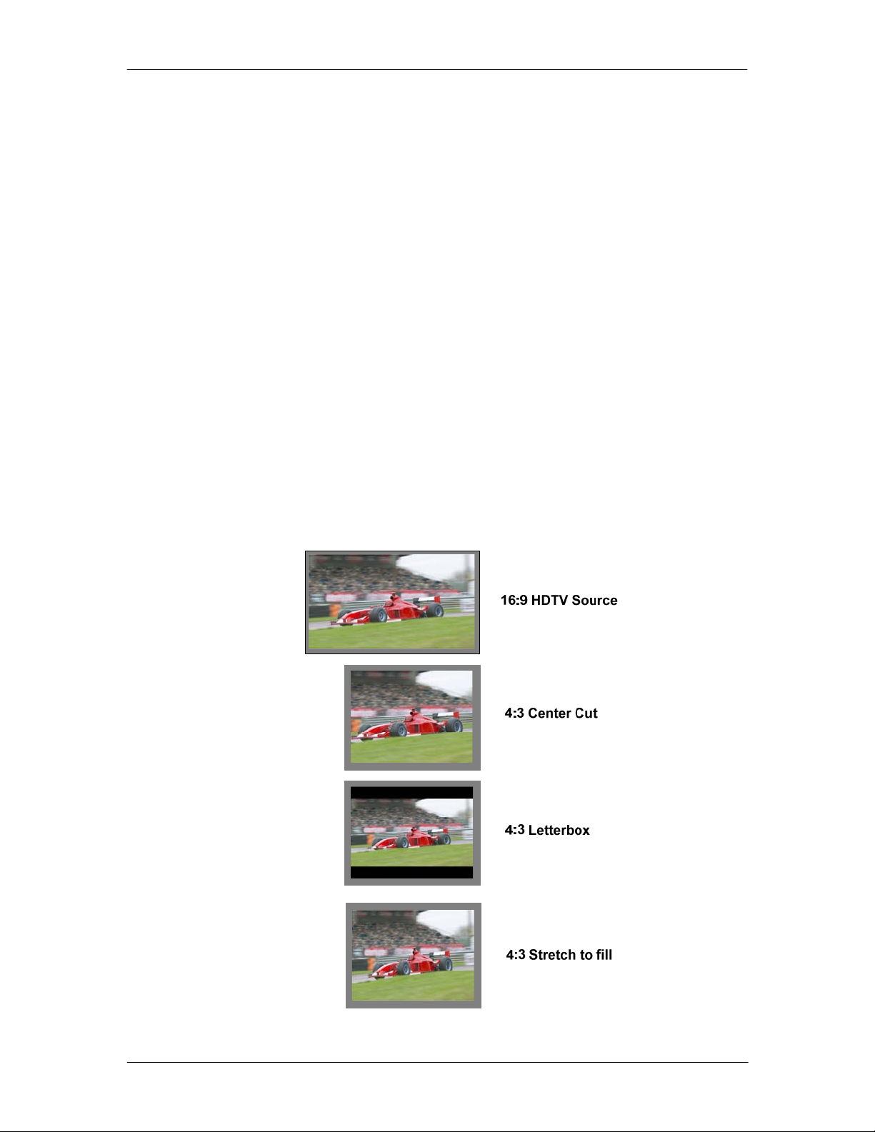
Down Conversion
The module has a selectable independent down converter and this will co nvert the
connected HD input standard into a SDTV output signal. Modes supported are as follows:
4:3 Letterbox
This takes the 16:9 aspect ratio of the input HD signal and fits it into the 4:3 SD aspect
ratio screen with black bars at the top and bottom of the image.
4:3 Center Cut
This mode cuts the center portion of the 16:9 input signal and fills the 4:3 SD aspect ratio
screen.
P VD 5600 Reference Manual. Rev 2.0
4:3 Stretch to Fill
This mode takes the 16:9 input signal and distorts (vertically stretches) the image to fit
the available 4:3 SD aspect ratio space.
Page 10 of 34
Page 11
P VD 5600 Reference Manual. Rev 2.0
SDTV Aspect Ratio Conversion
Each channel has a selectable independent SDTV Aspect Ratio converter and this will
convert the connected SD input standard either from a 4:3 input signal to a 16:9 output or
a 16:9 input signal to a 4:3 output signal.
Modes supported are as follows:
Conversion from 16:9 Input Aspect Ratio to 4:3 Output Aspect Ratio
4:3 Letterbox
This takes the 16:9 aspect ratio of the input signal and fits it into the 4:3 SD aspect ratio
screen with black bars at the top and bottom of the image.
4:3 Center Cut
This mode cuts the center portion of the 16:9 input signal and fills the 4:3 SD aspect ratio
screen.
4:3 Stretch to Fill
This mode takes the 16:9 input signal and distorts (vertically stretches) the image to fit
the available 4:3 SD aspect ratio space.
Page 11 of 34
Page 12

P VD 5600 Reference Manual. Rev 2.0
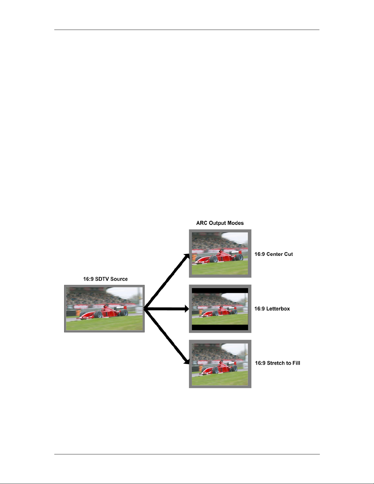
Conversion from 4:3 Input Aspect Ratio to 16:9 Output Aspect Ratio
16:9 PillarBox
This takes the 4.3 aspect ratio of the input signal and fits it into the 16:9 SD aspect ratio
screen with black bars at the left and right of the image.
16:9 Center Cut
This mode cuts the horizontal center portion of the 4:3 input signal and fills the 16:9 SD
aspect ratio screen.
16:9 Stretch to Fill
This mode takes the 4:4 input signal and distorts (horizontally stretches) the image to fit
the available 16:9 SD aspect ratio space.
Color Space Conversion
The Conversion options also provide integrated color space conversion capability which
will automatically compensate for the conversion of the wider 709 HD color space into the
more narrow 601 SDTV color space ensuring legal color reproduction. (Color sp ace
conversion is supplied as part of the UP/DOWN/CROSS conversion option)
NOTE. Color space conversion can be bypassed or set to only process
chrominance if desired.
Page 12 of 34
Page 13

Video Processing
Proc Amp Functions
Each of the two output channels has an associated video proc amp which pro v ides user
adjustable Gain / Saturation / Black Level and Hue using on screen sliders.
Aperture Correction
An adjustable horizontal aperture corrector is provided for each of the two output
channels. This can be used to add (or remove) image sharpness as required.
Note. When using the down converter the filtering process results in a very slight
loss of high frequency information (which is normal), the aperture corrector can
be used to compensate for this slight loss.
Test Patterns
Each of the two output channels has its own independent test pattern generator which
provides a wide selection of test patterns which can be switched into each output. (The
Test pattern will follow the selected output standard selected for each channel).
The selected test pattern is also available as one of the modes the synchronizer will
switch to when excessive video TRS errors are encountered. Possible synchronizer
actions when the input video errors become excessive are:
• Freeze Field 1
• Freeze Field 2
• Freeze Frame
• Selected Test Pattern
• Black
P VD 5600 Reference Manual. Rev 2.0
Programmable Video Delay
Each of the two SDI outputs has separate programmable video delays which can be set
(independently) between 0 and 5 frames (max). The adjustment is available in pixel, line
and full frame increments.
Note The Synchronizer (including the conversion options, if installed) has a fixed
one frame delay. The 0 > 5 frame user adjustment is additional delay relative to
the fixed one frame delay.
This adjustment will delay the video output relative to the connected reference by the
delay setting specified. (+ 1 frame fixed delay)
Functional Diagram
A functional diagram of the PVD 5600 is shown below:
Page 13 of 34
Page 14

NOTE. Some functions are
not shown or are shown as
“not implemented yet”. These
features will be added at a
later date. The module is fully
programmable so these
features can be easily added
to existing modules via
firmware upgrades.
P VD 5600 Reference Manual. Rev 2.0
Page 14 of 34
Page 15

Module Layout
P VD 5600 Reference Manual. Rev 2.0
Module Front Panel Module Rear Termination Panel
Cooling Fan
CardModule Layout
Note. Cooling fan operation is monitored and alarmed with the module alarm
LED and also within the LYNX control system.
Page 15 of 34
Page 16

Connections
Video
The PVD 5600 uses standard 75 Ohm BNC connectors. We recommend the use of high
quality video cable for digital video connections to reduce the risk of errors d ue to
excessive cable attenuation. Max cable lengths the module will support are shown below.
SDTV = 250m Belden 8281 (270Mbits/s)
HDTV = 140m Belden 1694A (1.4Gbits/s)
Note. Due to the compact design of the connection plate it will be necessary to
use a connection tool to secure the BNC video connectors.
Installation
If this module was supplied as part of a system it is already installed in the rack
enclosure. If the module was supplied as a field upgrade please follow the installation
procedure below.
This module has a double width rear connection panel, meaning it will occupy two slots of
a standard Series 5000 Card Rack. This is to accommodate the additional connections
needed for this module and to also provide adequate space for cooling in the rack. Up to
five P VD 5600 modules can be accommodated in a single Series 5000 rack frame.
NOTE. When using this module we highly recommend the use of the R FR 5011
Fan Front Rack Frame which provides additional airflow into the rack. If you
plan to install this module into empty slots in an existing rack with no fan front
cover - then please purchase the R FR 5001 Fan Front update ki t.
Each Card Module is supplied with a rear connection panel and mounting screws. Please
follow the procedure below for the installation of the card module into the Series 5000
Card Frame.
We recommend you power the rack down before installing any additional modules into an
existing card frame.
1. Select a free two slot space in the card frame where the CardModule will be
located.
2. Remove the blank connection panels from the rear of the rack (if fitted)
3. Install the rear connection panel using the screws supplied. Do not tighten the
screws fully
4. Slide the card module into the card frame and carefully check the CardModule
connects to the rear connection plate. The card should fit easily and should not
require excessive force to insert - if you feel any resistance, there could be
something wrong with the rear connection panel location. Do not
P VD 5600 Reference Manual. Rev 2.0
NOTE Observe static precautions when handling card. Please see ESD
warnings on Page 5.
try and force
Page 16 of 34
Page 17

P VD 5600 Reference Manual. Rev 2.0
the connection this may damage the connectors. Remove the rear connection
panel and check alignment with the CardModule.
5. Insert and remove the CardModule a few times to ensure correct alignment and
then tighten the two screws to secure the rear connection plate.
6. Power up the rack and check the module LED’s and matrix display illuminate.
Check the module is automatically logged into the control system device tree.
(It may take a few seconds for the control system to “discover” the new module )
NOTE. The use of the optional control system is mandatory
control and setup of this module. If you do not have the control system,
then please contact your LYNX representative for details on how to
upgrade your rack with the LYNX control system.
for the
Page 17 of 34
Page 18

Settings and Control
The P VD 5600 module has an integrated micro-controller, which enables the module to
be configured and controlled locally using the multifunction switch and 4 character dot
matrix display, or from remote using a GUI interface when using one of the optional
controllers and control software.
NOTE. This module is extremely compact and flexible with hundreds of possible
user settings. It is not practical to make all these settings available on the local
dot matrix display. The use of the control system is mandatory
!
Once set, all settings are automatically saved in non-volatile internal memory. (Flash
RAM) The module will always recall the last used settings.
vast array of settings possible. Please refer to the GUI section of this manual for
details on the control provided. Some basic module settings are possible via the
local controls, which are detailed below.
P VD 5600 Reference Manual. Rev 2.0
to access the
Multi-function Switch
Side Front
Switch Operations
Up Down
Enter
Multi Function Switch
The CardModule is equipped with a multi-function switch located on the front bottom
edge of the card. (See above)
Using the Local Display Menus
Making local adjustments to the module is done using the multifunction switch and the
integrated 4-character dot matrix display. The menu system is layered, and navigation
through the system is done using the UP and DOWN functions of the switch. ENTER is
used to move between menu levels and also enter a selection.
Switch Function Operation
UP Move UP within a level
DOWN Move down within a level
ENTER Change levels / Make selection
Page 18 of 34
Page 19

P VD 5600 Reference Manual. Rev 2.0
Menu Structure
The Menu structure is defined in the next table, and can be used to help navigating
through the menu system.
ENTER moves between levels
UP/DOWN moves between items within the level
When a new setting is entered the system will jump back one level in the menu system.
• The “back” selection in the menu structure will take you back one level when
selected.
• When an item is selected which has several setting possibilities the first value
displayed will be the value currently stored in the system. The order of the
available settings for any menu item in the table supplied does not represent the
order the settings will actually be displayed.
• If left unattended, the menu will default to the root display after a short timeout.
LEVEL 1 LEVEL 2 LEVEL 3 Notes
P VD 5600 Root Display
REF
EXT
INT
back
FPS Output frame rate selection
60
59
50
AUTO
back
RSET Reset Factory Defaults
NO
YES
back
back
Reference Selection
Reference taken from module rear connection panel
Reference taken from common rack reference
All outputs jammed to 60Hz frequency frame rate*
All outputs jammed to 59.94Hz frequency frame rate*
All outputs jammed to 50Hz frequency frame rate*
Output frame rate is derived from connected reference (default)
Reset factory defaults
Page 19 of 34
Page 20

LED Status Indicators
The P VD 5600 module has LED indicators that serve as alarm and status indicat ion for
the module. Function is described below.
SDI Status LED 1
LED Color Indication
Green SDI Present and OK
Yellow SDI Frame Rate Mismatch
Red No SDI 1 Signal Connected
Ref Status LED 3
LED Color Indication
Green Reference Present
Yellow Reference Present, but not used
Red Reference not present – but required
(Mismatch between the fixed output frame
rate and the SDI input. Conversion taking
place)
(Module is set to free run with no lock to
external reference)
(Module is set to “lock to reference”)
P VD 5600 Reference Manual. Rev 2.0
ALARM LED
LED Color Indication
Green Normal Operation
Red Problem with SDI input
Red Flashing Cooling Fan Failure
Note. The Alarm LED can be seen with the rack front cover
fitted
Page 20 of 34
Page 21

Control System GUI
All LYNX CardModules support a computer interface which allows setting the modules
parameters using a simple GUI interface. Access to all standard features and in some
cases extended features is possible using this interface. The complex nature and
extensive user settings provided on the PVD 5600 requires
system.
Note. Any settings made using the control system overrides any local settings
made on the module. All settings are stored in internal flash ram and will survive
power cycles and long term storage.
The following GUI screenshots and descriptions shown below describe the settings and
adjustments possible for the PVD 5600 CardModule.
P VD 5600 Reference Manual. Rev 2.0
the use of the control
The above screenshot shows the complete module GUI. The Device info area contains
information about the module including name and firmware revision. If used as part of a
larger system (using the LYNX central control system) the modules position a nd physical
location is displayed above the “locate” button.
Note. The Locate function us a tool used to quickly identify a module in larger
systems. Selecting “locate” will flash the module alarm LED yellow. (This does
not effect module operation)
The first screen displayed when the module is selected is the Main Tab this is a graphical
representation of the modules overall function and signal flow (left to right). Clicking on
Page 21 of 34
Page 22

the processing boxes will link to other GUI screens with more controls for these specific
functions.
The area at the bottom of the screen is the error log. Any fault condition (or event) will be
time stamped and entered into the log.
There are a number of “Tabs” along the top of the screen which splits up the module
settings into a number of logical displays. The various GUI screens and primary functions
are described below.
Main Tab
This screen is the main interface and is presented first when the module is displayed in
the GUI. The layout replicates module “block” functions and signal flow from left to right.
P VD 5600 Reference Manual. Rev 2.0
The primary purpose of this screen is to show the overall signal flow through the module
and allow easy navigation to other areas. Input standards and formats are auto detected
and displayed in the GUI. Parameters will be annunciated in different colors to show
status (green = good, red = problem, yellow = caution etc).
REF in Select
There is a select list next to the REF in connection. This selects if external reference is to
be used from the common rack reference input or the board connection plate reference
input.
With the selection above the FSYNC box the reference for the frame synchronizer can
also be derived from the digital input. This is useful for applications, where the
P VD 5600 is used as a video delay line.
Page 22 of 34
Page 23

Signal Routing
In the center of the screen there is an area where the internal signal routing can be
changed. This area is fundamental to the modules basic function. Here the internal video
signal can be routed through (or bypassing) the up/down/cross conversion option.
Selecting a cross point via the radio button closes the connection (operation is self
explanatory)
Test Patterns
In each of the two output channels it’s possible to switch the test pattern on from the main
tab if required. (Also selectable from the individual Proc Out GUI screen)
Video Proc Tab
This tab will bring up the configuration screen for the conversion option (if fitted), this
screen can also be accessed by clicking on the “Conv1” box in the flow diagram on the
main GUI screen.
Note. If the conversion option have not been installed then the selection in the
Video Converter box will be grayed out.
P VD 5600 Reference Manual. Rev 2.0
Page 23 of 34
Page 24

General Video Settings
The first area covers some General setup parameters for the frame sync operation.
External Reference Source
It is possible to take the external reference signal from two sources. Either from the
common rack reference (an external reference connection to the rack frame which is fed
to all cards installed in the rack) or via the BNC connection provided on the module rear
connection panel. Selections provided are:
• External (board) = Via module rear connection panel
• Internal (rack) = Common rack reference
Frequency Pre-select
This is where the Frame synchronizer output frequency (or frame rate) is selected. This
can be jammed into a format which will never change (regardless of the connected
reference or the connected input video source). If a signal with an incompatible frame
rate is connected then a rudimentary standards conversion will take place to maintain a
constant output frame rate. This conversion process drops and repeats fields/frames and
should not
It is also possible for the synchronizer to configure the output frame rate based upon the
connected reference. This is the default setting for the module. Possible settings are:
• 50Hz
• 59.94Hz
• 60Hz
• Follow (last) reference (default)
The “Current Frequency” area in the GUI is showing the frequency the frame
synchronizer is running in currently (useful if the follow last reference selection is made)
be considered broadcast quality.
Note. For systems without the up/down/cross conversion option fitted then this
conversion will only take place between compatible video form ats.
Note. The synchronizer is supplied from the factory with the last stored referen c e
as 50Hz. With no reference connected its possible to change the last stored
reference to something else. Simply select the desired fixed frequency and then
re-select follow last reference. Now the module will use this new setting through
a power cycle
Also, this value will not
Defaults” operation, the stored setting is preserved.
P VD 5600 Reference Manual. Rev 2.0
be restored to 50Hz following a “Restore Factory
Device Status
This area is used to show the detected internal and external temperature of the Module. If
the internal temperature exceeds 80ºC then the module will log a “over temperature”
event in the control system error log.
SDI Input
The next section on the GUI is sectioned SDI 1. This is where the reaction of each
channel is defined in case of excessive video errors. The output can be configured to
“freeze” or pass the input signal transparently when errors are encountered. If configured
to pass the video transparently then all video errors and disturbances are passed to the
output.
Page 24 of 34
Page 25

The synchronizer is very robust in its ability to handle poor quality input signals but there
may be occasions where excessive errors cannot be recovered by the synchronizer. This
is generally qualified by TRS errors. TRS means “Timing Reference Signal” and is a
sequence of digital values embedded in the SDI data stream. If the frame synchronizer
cannot recover these errors, then the channel will freeze the video until the errors can be
recovered. One function of the synchronizer is to repair any bad TRS values ensuring a
stable and technically correct video stream is delivered on the outputs. Selections for
each channel are as follows:
• Freeze on TRS errors
• Transparent
Video Converter
This section will only be active if the Up/Down/Cross conversion option is purchased.
Options are installed via a license strings (purchased separately) these are entered into
the module to activate the options. Option licenses are managed / entered using the
Options Tab in the GUI.
Note. Currently the option only supports down conve rsion, the up / cross
conversion functionality will be added at a later date (at no additional charge)
Down Converter Mode (optional)
The down converter provides three modes which can be selected using the drop down
selections provided:
• Letterbox 16:9
• Center cut 4:3
• Stretch to Fill
P VD 5600 Reference Manual. Rev 2.0
SDTV Aspect Ratio Converter Mode
The Aspect Ratio converter provides three modes for 16:9 to 4.3 conversion and three
modes for 4.3 to 16:9 conversion, which can be selected using the drop down selections
provided:
16:9 to 4:3 conversion
• Letterbox
• Center cut
• Stretch to Fill (vertical)
4:3 to 16:9 conversion
• Pillar Box
• Center cut
• Stretch to Fill (horizontal)
The “Input format” and the “signal used for the outputs” indicate which input format is
routed to the specific conversion channel, and also indicates which of the two outputs the
converter output is routed to. (These will change if the internal signal routing is changed).
Page 25 of 34
Page 26

Output Proc Tabs
There are two “Out Proc” tabs provided, one for each of the two outputs provided. This is
where the individual video processing functions are set for each channel. The two “Out
Proc” tabs have identical adjustments.
P VD 5600 Reference Manual. Rev 2.0
Color Space Conversion
Note. This is only active when the conversion option(s) are installed
This is where the color space conversion functionality is configured. This is used to
ensure correct color reproduction on the outputs. HD color space is wider than SDTV
color space so there is the possibility of some illegal colors being reproduced if the color
space is not converted. Possible selections are:
• Convert (convert the video signal)
• Bypass (perform no conversion)
• Luma in Bypass (only convert Chroma portion of signal)
Aperture Correction
Horizontal aperture correction is provided for each output channel, whi ch can be used to
sharpen or soften the video signal. (This is sometimes required for d own converted video
signals as the filtering process rolls off the high frequency very slightly). If adjusted in the
positive direction this will increase sharpness, if adjusted in the negative direction this will
soften the image.
There is a check box to switch aperture correction ON and OFF and an adjustment range
Page 26 of 34
Page 27

The numerical adjustment range provided is + 80 to -30, and is changed by clicking on
the “+” or “-“ Buttons.
Note. Aperture correction OFF is the same as a Zero setting in the adjustment
range
H and V Blanking
A checkbox selection is provided for H (Horizontal) and V (Vertical) blanking. When
selected the video output will have new blanking applied in both of these areas (which will
overwrite any information in the vertical and horizontal blanking intervals).
Video Delay Adjustment
Each video output can be delayed relative to the reference sync up to a maximum of 5
frames. This is usually used for downstream system timing applications. The delay is
adjustable in the following increments:
• Frames
• Lines
• Pixels
• Time (ns)
Depending on preferences you can use one or all of the adjustments provided to set the
total video delay.
Note. The adjustable delay applied is in addition
processing delay of the module.
P VD 5600 Reference Manual. Rev 2.0
to the fixed one frame
Settings
This area is where the freeze function is defined and also the action (and settings) of the
integrated test pattern generator. (Each channel has its own independent test pattern
generator)
Freeze Mode
When the synchronizer encounters excessive TRS errors it can be set to freeze or pass
the video transparently (selected on the Video Proc tab). If Freeze is selected then the
behavior of the freeze function is selected using the drop down selections. These are:
• Freeze Field 1
• Freeze Field 2
• Freeze Frame
• Display (pre-selected) Test Pattern
• Black
Note. If the pre-selected test pattern is selected this will be used in the respective
channel video format and NOT influenced by the “Test Pattern Standard”
selection mentioned below.
Page 27 of 34
Page 28

Test Pattern Pre-select
A wide range of patterns is provided which can be selected using th e drop down selection
provided. The pre-selected pattern will be used if the freeze mode is set to “test pattern”
and will also the pattern used if “test pattern on” is selected. Patterns provided are:
• Full field Black
• Full field White
• Full field Yellow
• Full field Cyan
• Full field Green
• Full field Magenta
• Full field Red
• Full field Blue
• 15% Grey (full field)
• 75% Color bars
• 75% Color bars over Red
• Pathological PLL/EQ
Test Pattern Standard
With no input signal connected the module can be used a stand alone test generator
using this selection is possible to configure the test pattern into any of the supported
standards, or it can be set to follow the last input standard. Settings provided are:
• Follow last input (default)
• SDTV
• 720P
• 1080i
Note. Signal Frame rate (or frequency) is set on the Video Proc Tab (this is the pre
selected frequency)
P VD 5600 Reference Manual. Rev 2.0
Test Pattern Enable
This checkbox simply switches on the pre-selected test Pattern. (The same can be done
using the Test Pattern checkbox on the Main Tab)
Video Adjustments
Four on screen sliders are provided to allow for the adjustment of individual video
parameters. Separate sliders are provided for video Brightness (gain), Saturation,
Pedestal (Black level) and Hue.
Default (null) settings are 0% (this is the default). Sliders can be quickly return ed to the
factory null (or transparent) settings using the buttons provided at the bottom of each
slider.
Page 28 of 34
Page 29

Options Tab
One tab on the GUI is reserved for “Options“ This is where the option license codes are
entered to unlock the embedded firmware options. Currently there is one option available
which is the DOWN conversion option.
It’s possible to install a conversion option into the PVD 5600. This option must be
purchased and installed separately.
P VD 5600 Reference Manual. Rev 2.0
If the module was purchased with options pre-installed then you will see the option status
as green (Active).
If you would like to purchase this option after delivery, then you will need to purchase the
license codes from LYNX Technik.
Click the “request code” button next to the channel you wish to activate. A number will be
displayed, Please forward this number with your purchase order to your authorized LYNX
dealer or representative. When you receive the license string simply type it (or paste it
using the windows clipboard) into the area provided and press “activate”. Activation is
confirmed when the option status turns green.
Page 29 of 34
Page 30

Events Tab
The Events Tab is where the module alarming and error notifications are configured for
the module.
P VD 5600 Reference Manual. Rev 2.0
The GUI has an integrated error log, which is a simple text log file stored in the controller
PC. This will record an event and timestamp it. The log can be seen at the bottom of the
GUI screen and can be scrolled through using the scrolling bar.
Log in GUI Function
Events are selectable, you can chose if you want to record a particular event in the log
(or not) or configure it to only record one side of the event. (For example you might want
to log when a SDI input was removed but do not want to log when it came back). The
ON/OFF trigger can be configured for each of the available events shown in the list and is
setup using the checkboxes provided.
Alarm Activation
By default all alarm conditions are activated (checked), by de-selecting a specific alarm
condition I this column you are telling the module to ignore this condition completely. It
will not color the alarm LED, log and event in the GUI or send a SNMP trap. This is useful
if for example you never have anything connected to AES input 2 and want the card to
ignore this input condition completely you would simply de-select “AES Input 2 No Input”
and it will be ignored.
Page 30 of 34
Page 31

SNMP Support
If the system is using a RCT 5030 Master Controller and the SNMP option is installed
then the “SNMP Trap” columns become available.
Here you can configure what events you would like to transmit a “SNMP trap” for over the
network. (This has no impact or influence over the internally error log maintained by the
LYNX control system)
(Internal LYNX error logging and external SNMP traps can be configured independently).
Note. The simulated event is part of the GUI simulator and allows us to force a
particular error condition for testing and demonstration purposes.
P VD 5600 Reference Manual. Rev 2.0
Page 31 of 34
Page 32

P VD 5600 Reference Manual. Rev 2.0
Specifications
Video Input
Signal Type Serial digital video SMPTE 292M, 344M, 259M-C
Input standards HDTV 1080i 59.94Hz / 60Hz / 50Hz /
720P 59.94Hz / 60Hz / 50Hz
SDTV 525 59.94Hz / 625 50Hz.
( Field upgradeable for additional format support in future )
Connector BNC
Impedance 75 Ohm
Cable Equalization Up to 250m Belden 8281 (270MHz)
Up to 140m Belden 1694A (1.485GHz)
Return Loss > 15 dB (270MHz)
> 10dB (1.485GHz)
Reference Input
Signal Type Analog Bi-level / Tri-level (auto detect) cross lock compatible
No of inputs 1 x External or internal rack reference (selectable)
(PVD 5610 DW provides a loop out of reference)
Connection BNC
Impedance 75 Ohm
Video Outputs
Signal Type Serial digital video SMPTE 292M, 344M, 259M-C
Output standards 1080i 59.94Hz / 60Hz / 50Hz
720P 59.94Hz / 60Hz / 50Hz
525 59.94Hz / 625 50Hz.
No. Of outputs 2 separate outputs with 2 x SDI out of each output (4 total)
(mapped to any internal signal channel)
Connector BNC
Impedance 75 Ohms
Jitter < 0.2 ui (270MHz) < 0.25 ui (1.485GHz)
Return Loss > 15 dB (1.5GHz)
Video Processing
Delay adjustment range Up to 5 frames of programmable delay in pixel / line / frame increments. Independent for the 2
outputs
Minimum delay 1 Frame ( including up/down/cross conversion options)
Video adjustments Gain / Saturation / Hue / Black Level
Aperture correction Horizontal only, adjustable for each output channel (3)
Color space conversion 601 > 709 or 709 > 601 or transparent (selectable) Note. Requires conversion option(s)
Operating Modes
Frame Sync Basic SD / HD Multi-rate Frame Synchronizer
Down / ARC
conversion + frame
sync
Control
Local Controls Local alphanumeric display with integrated menu system for setting “basic” module
Remote Control Comprehensive remote control and status monitoring supported when used with a LYNX
External GPI Single GPI input on BNC connector. (Function configurable)
Electrical Specifications
Operating Voltage 12 VDC
Power Consumption 10 W
Safety IEC 60950/ EN 60950/ VDE 0805
Requires Firmware option for Down Conversion
parameters.
Controller option. The use of the control system is mandated for this module
Page 32 of 34
Page 33

P VD 5600 Reference Manual. Rev 2.0
Mechanical
Size 283mm x 78mm
Weight CardModule 120g, connector plate 50g
Rack space Requires 2 slots in rack frame (max 5 modules per frame)
Ambient
Temperature 5°C to 40°C Maintaining specifications
Humidity 90% Max non condensing
Page 33 of 34
Page 34

Service
Parts List
Due to the very dense design and high level of integration there the module is not user
serviceable. Please contact LYNX for repairs or to request an exchange unit.
There is one consumable part used on this module which is the cooling fan. A service kit
is available to exchange the fan. Ordering information below.
Part type: Cooling Fan Service Kit Series 5000 CardModules
Technical Support
If you are experiencing problems, or have questions please contact your local distributor
for further assistance.
Technical support is also available from our website.
Please do not return products to LYNX without an RMA. Please contact your authorized
dealer or reseller for more details.
More detailed product information and product updates may be available on our web site:
P VD 5600 Reference Manual. Rev 2.0
www.lynx-technik.com
Contact Information
Please contact your local distributor; this is your local and fastest method for obtaining
support and sales information.
LYNX Technik can be contacted directly using the information below.
Address LYNX Technik AG
Brunnenweg 3
D-64331 Weiterstadt
Germany.
Website
E-Mail
LYNX Technik manufactures a complete range of high quality modular products for
broadcast and Professional markets, please contact your local representative or visit our
web site for more product information.
www.lynx-technik.com
info@lynx-technik.com
Page 34 of 34
 Loading...