

Lynx NGT-9000 Series, NGT-9000+, NGT-9000RD, NGT-9000D, NGT-9000R Pilot's Manual
Aviation Products
Pilot’s Guide for Models
NGT-9000
NGT-9000+
NGT-9000D
NGT-9000R
NGT-9000R+
NGT-9000RD

Document Precedence
This Pilot’s Guide provides general information about the operation
of the NGT-9000. Refer to your FAA-approved Airplane Flight Manual
(AFM) and its flight manual supplements for information specific to
your aircraft. If there is conflicting information between the AFM and
this guide, the AFM takes precedence over this guide.
Disclaimer
This Pilot’s Guide is subject to change without notice. The illustrations
in this guide are typical for the Lynx NGT-9000.
Screen information may look different on displays interfaced with
the Lynx NGT-9000. Refer to the pilot’s guide for that display for a
description of how information is depicted.
All pilots/operators are reminded that the airborne equipment that
displays other ADS-B equipped aircraft and transponder equipped
aircraft via TIS-B is only for pilot situational awareness. This equipment
is not approved as a collision avoidance tool. Any deviation from an air
traffic control clearance based on cockpit information must be approved
by the controlling ATC facility prior to commencing the maneuver.
Uncoordinated deviations may place an aircraft in close proximity to
other aircraft under ATC control not seen on the airborne equipment
and may possibly result in the issuance of a pilot deviation.
ADS-B is currently being deployed throughout the National Airspace
System (NAS). The availability of ground based transceivers (GBT) is
limited to selected areas. For information regarding the FAA’s system
of ADS-B, TIS-B, ADS-R, and FIS-B refer to the FAA’s Aeronautical
Information Manual sections 4-5-7 to 4-5-10.
Revision Highlights
Incorporate Remote Mount Versions•
Pilot’s GuideA

Pilot’s Guide
Methods and apparatus disclosed and described herein have
been developed solely on company funds. No government or other
contractual support or relationship whatsoever has existed which
in any way affects or mitigates proprietary rights of ACSS® in these
developments. Methods and apparatus disclosed herein may be
subject to U.S. Patents existing or applied for. ACSS® reserves the right
to add, improve, modify, or withdraw functions, design modifications,
or products at any time without notice.
Export Notice
This technical data is controlled under the Export Administration
Regulations (EAR) and may not be exported without proper
authorization by the U.S. Department of Commerce.
Product Part No. 9029000-20000 (panel mount)
9029000-40000 (remote mount)
Document Part No. 0040-17000-01 (Revision C)
© Copyright 2015
ACSS
Refer to the following for additional copyright information:
®
https://www.l-3avionics.com/open-source.aspx
https://www.l-3avionics.com/ customer-support/
flight-data-info/open-source-software-report.aspx
Trademarks
Lynx ® is a registered trademark of L-3 Avionics Systems
Patent Pending
Distributed with permission by:
L-3 Avionics Systems.
5353 52nd Street, S.E.
Grand Rapids, MI 49512 USA
Customer Support (800) 453-0288
International (616) 949-6600
Avionics Systems
Pilot’s Guide i
FAX (616) 977-6898
www.L-3avionics.com

Pilot’s Guideii
Table of Contents
Chapter 1: Description
INTRODUCTION .........................................................................................1-1
SPECIFICATIONS ...............................................................................1-2 / 1-3
Pilot Advisory ...............................................................................................1-4
Functional Description .................................................................................1-5
Options ..................................................................................................1-6
ADS-B ....................................................................................................1-6
ADS-R ....................................................................................................1-7
TIS-B System Capabilities .....................................................................1-8
Traffic Awareness System ...................................................................1-10
FIS-B System Capabilities ................................................................... 1-11
Equipment Description ..............................................................................1-14
Standard Equipment ............................................................................1-14
Optional Equipment ...................................................................................1-14
GPS Antenna and Internal GPS Receiver ...........................................
L-Band Antenna ...................................................................................
Detachable Configuration Module (DCM) ............................................1-14
Directional Antenna ..............................................................................
Alternate Displays ................................................................................1-15
Personal Electronic Device (PED) .......................................................
WiFi Serial Adapter ..............................................................................
CP-2500 Control Panel ........................................................................
1-14
1-14
1-15
1-15
1-15
1-15
Chapter 2: Operation
Introduction ..................................................................................................2-1
Power (Remote Mount) ...............................................................................2-1
Normal Operation (Remote Mount) .............................................................2-2
Power (panel Mount) ...................................................................................2-2
Splash Screen .......................................................................................2-2
System Status / Versions Screen ..........................................................2-3
Flight ID Screen (optional) .....................................................................2-4
Normal Operation ..................................................................................2-4
Basic Operation ...........................................................................................2-5
Screen Buttons ......................................................................................2-5
Application Screens ...............................................................................2-7
Transponder Operation ...............................................................................2-9
Squawk Code ........................................................................................2-9
Current Pressure Altitude .....................................................................2-10
Flight ID / Call Sign ..............................................................................2-10
Mode Control .......................................................................................2-10
Transponder Reply ..............................................................................2-10
IDENT Button .......................................................................................2-10

Pilot’s Guide iii
Table of Contents (continued)
Squawk VFR Button ............................................................................2-11
MSG Button .........................................................................................2-11
On-GND Indicator ................................................................................
System Test Button .............................................................................. 2-11
Traffic Operation ........................................................................................2-13
Traffic Screen .......................................................................................2-14
Ownship Symbol .................................................................................2-14
Traffic Symbols ....................................................................................2-14
Traffic Display Priority ..........................................................................2-15
Zoom Buttons ......................................................................................2-15
Range Rings ........................................................................................2-17
Traffic Altitude Mode ............................................................................2-17
TFC Button ..........................................................................................
Transponder Banner ............................................................................2-18
MSG Button .........................................................................................2-18
Traffic Mode Indicator ..........................................................................2-18
Traffic
Traffic
Options - Status .............................................................................2-19
Options - Settings ........................................................................
Selected Traffic Button (i) ....................................................................2-21
Traffic Information Window ..................................................................2-21
TIS-B No Coverage Indicator ...............................................................2-21
Selected Traffic ID ...............................................................................2-22
Selected Traffic GS ..............................................................................2-22
True Track (TRK) .................................................................................
Weather Operation ....................................................................................2-23
FIS-B Graphic Application ....................................................................2-23
NO FIS-B COVERAGE INDICATOR ..................................................
Map Elements ............................................................................... 2-24
Information Button (i) .................................................................... 2-24
TFR Map Elements ........................................................................2-25
AIRMET and SIGMET Map Elements ............................................2-25
METAR ...........................................................................................2-25
NEXRAD Map Elements ................................................................2-26
Traffic Button ..................................................................................2-27
Zoom Buttons .................................................................................2-27
Display Range Indicator .................................................................2-27
Panning ..........................................................................................2-27
North Indicator ...............................................................................2-27
Airport ID Indicator .........................................................................2-27
Orientation Button ..........................................................................2-27
Map
Options Button ..........................................................................2-19
Options Screen ...................................................................2-19
Options Button .......................................................................2-28
2-11
2-18
2-20
2-22
2-23

Pilot’s Guideiv
Table of Contents (continued)
On/Off Option Screen ....................................................................2-28
Weather Map Legend Screen ....................................................2-28
Banner .......................................................................................2-28
Display Area ...............................................................................2-30
Declutter Option Screen.............................................................2-30
Weather Map Text Screen ............................................................. 2-31
Display Area ...............................................................................2-31
Banner .......................................................................................2-31
Product Select List Window ......................................................2-32
FIS-B Graphic Winds & Temp Application ...........................................2-32
Traffic Button ................................................................................. 2-33
Aloft Button ................................................................................... 2-34
Panning ......................................................................................... 2-34
Zoom Buttons ................................................................................ 2-34
Issue Valid Time Indication ........................................................... 2-34
Ownship Symbol .......................................................................... 2-34
North Indicator .............................................................................. 2-34
Flight Level Selection .................................................................... 2-34
FIS-B Textual Application .....................................................................2-35
Display Area .................................................................................. 2-35
Banner .......................................................................................... 2-35
Traffic Button ................................................................................. 2-35
Airport Button ................................................................................ 2-36
Edit Airport ID Window ...............................................................2-36
Favorites Button ........................................................................... 2-37
Favorites Pick List Window ........................................................2-37
Product Button .............................................................................. 2-38
Product Pick List Window ..........................................................2-38
Maintenance Mode ....................................................................................2-38
Chapter 3: Controls and Indicators
Introduction ..................................................................................................3-1
Cockpit Switches .........................................................................................3-1
IDENT ....................................................................................................3-1
Indicator
TAS Alert ................................................................................................3-1
ADS-B Fail .............................................................................................3-1
Control Panel Options .................................................................................3-2
RS-232 Control Panel ............................................................................3-2
RS-422 Control Panel / External Display ...............................................3-2
RS-232 WiFi Interface ...........................................................................3-3
Alternate Display .........................................................................................3-2
Other Traffic Symbol .............................................................................3-2
Proximity Advisory Symbol ....................................................................3-2
Off-Scale Traffic Advisory (TA) ..............................................................3-2
Ownship Symbol ....................................................................................3-3
lamps ......................................................................................3-1

Pilot’s Guide v
Table of Contents (continued)
Indicators ...............................................................................................3-3
WiFi Interface .........................................................................................
Aural Announcements .................................................................................3-3
Extended Audio Cal
Audio Inhibit .................................................................................................3-4
CP-2500 Control Panel................................................................................3-4
Power On/off ..........................................................................................
Normal Operation ..................................................................................
Chapter 4 Principles of TAS Operation
Introduction ..................................................................................................4-1
Sensitivity Levels .........................................................................................4-1
Sensitivity Level A ................................................................................. 4-1
Sensitivity Level B ................................................................................. 4-2
Audio Inhibit .................................................................................................4-2
Audio Inhibit (GPWS or EGPWS) ................................................................4-4
TA Symbol Duration .....................................................................................4-4
Other aircraft ground Filtering......................................................................4-4
Interference Limiting ....................................................................................4-4
Chapter 5: Troubleshooting
Introduction ..................................................................................................5-1
General display conditions ..........................................................................5-1
System Status Messages ............................................................................5-3
Invalidities ....................................................................................................5-4
louts ........................................................................3-4
3-3
3-5
3-6
Appendix A: Record Of Important Information ...................................... A-1
Notes ................................................................................................ A-2 / A-3

Pilot’s Guidevi
List of Illustrations
Figure 1-1: Example Of Panel Mount Lynx NGT-9000 ...............................1-2
Figure 1-2: Example Of Remote Mount Lynx NGT-9000 ............................1-5
Figure 1-3: Example Of Own Aircraft UAT, 1090ES & TAS Traffic ...............1-9
Figure 2-1: Example Of Splash Screen ......................................................2-2
Figure 2-2: Example Of System Status / Version Screens ..........................2-3
Figure 2-3: Example Of Flight Id Screen .....................................................2-4
Figure 2-4: Example Of Normal Operation ..................................................2-4
Figure 2-5: Transponder Application Screen ...............................................2-9
Figure 2-6: Squawk Code Edit Screen ........................................................2-9
Figure 2-7: Example Of System Test Screen ............................................ 2-11
Figure 2-8: Traffic Applications Screen ......................................................2-13
Figure 2-9: Traffic Display Modes And Traffic Zones .................................2-18
Figure 2-10: Traffic Options Screen - Status .............................................2-20
Figure 2-11: Traffic Options Screen - Settings ...........................................2-21
Figure 2-12: Example Of Traffic Information Window ...............................2-22
Figure 2-13: Weather Map ........................................................................2-23
Figure 2-14: Example Of Nexrad Weather Map ........................................2-24
Figure 2-15: On/Off Options Screen ..........................................................2-28
Figure 2-16: Weather Map Legend Screen ...............................................2-29
Figure 2-17: Declutter Option Screen ........................................................2-30
Figure 2-18: Weather Map Text Screen .....................................................2-31
Figure 2-19: Product Pick List Window......................................................2-32
Figure 2-20: Aloft Map Screen ...................................................................2-32
Figure 2-21: Winds Aloft Map Elements ....................................................2-33
Figure 2-22: FIS-B Textual Application ......................................................2-35
Figure 2-23: Example Of Edit Airport ID Window ......................................2-36
Figure 2-24: Example Of Favorites Window ..............................................2-37
Figure 2-25: Example Of Product Pick List Window ..................................2-38
Figure 2-26: Maintenance Screens ...........................................................2-39
Figure 4-1: Traffic Display Mode And Tas Traffic Zone Graphic .................4-5
List of Tables
Table 1-1: Model options .............................................................................1-1
Table 1-2: Description of FIS-B Available Information ............................... 1-11
Table 2-1: Button Functions .........................................................................2-5
Table 2-2: Left Screen Applications .............................................................2-8
Table 2-3: Right Screen Applications ...........................................................2-8
Table 2-4: Traffic Symbols .........................................................................2-16
Table 2-5: Airport Symbols.........................................................................2-25
Table 4-1: Traffic Advisory Situations ..........................................................4-3
Table 5-1: General Display Conditions for the Panel Mount NGT-9000 .....5-1
Table 5-2: Troubleshooting for the Panel Mount Lynx NGT-9000 ................5-4
Table 5-3: Troubleshooting for the Remote Mount Lynx NGT-9000 ............5-4

Pilot’s Guide vii
List Of Abbreviations and Acronyms
° Degree
AC Advisory Circular
ABV Above
ADS-B Automatic Dependant Surveillance – Broadcast
ADS-R Automatic Dependant Surveillance – Rebroadcast
AFM Airplane Flight Manual
AGL Above Ground Level
AIRMET Airmen’s Meteorological Information
ALT Altitude
ATC Air Traffic Control
ATCRBS Air Traffic Control Radar Beacon System
BLW Below
BRT Brightness
CDTI Cockpit Display of Traffic Information
CONUS Contiguous United States
CPA Closest Point of Approach
DCM Detachable Configuration Module
DO- RTCA Document
EAR Export Administration Regulations
EGPWS Enhanced Ground Proximity Warning System
FAA Federal Aviation Administration
FDE Fault Detection and Exclusion
FIS-B Flight Information Service - Broadcast
fl Foot-Lambert
ft Feet
ft/min Feet Per Minute
GA General Aviation
GBT Ground Based Transceiver
GALT GPS Altitude
GND Ground
GPS Global Positioning System
GS Ground Speed
GPWS Ground Proximity Warning System
HAE Height Above Ellipsoid
HPL
HPLFD Horizontal Protection Level using a weighted FDE algorithm
hPa Hectopascals
Hz Hertz
ICAO International Civil Aviation Organization
ID Identification
IDENT Identification
InHg Inches of Mercury
kt/kts Knot (s)
lbs pounds
max Maximum
Horizontal Protection Level Using SBAS error estimates
SBAS

List Of Abbreviations And Acronyms (cont.)
METAR Aviation Routine Weather Report
MHz Mega Hertz
MSG Message
MSS Multilink Surveillance System
NACp Navigation Accuracy Category for Position
NAR Non Altitude Reporting
NAS National Airspace System
NEXRAD Regional and Next-Generation Radar
NIC Navigation Integrity Category
NOTAM Notices to Airmen
NM or nmi Nautical Miles
NRM Normal
OT Other Traffic
PA Proximity Advisory
PALT Pressure Altitude
PED Personal Electronic Device (e.g., tablet)
PIREP Pilot Report
P/N Part Number
R Reply
RAIM Receiver Autonomous Integrity Monitoring
REF Reference
RTCA Radio Technical Commission for Aeronautics, Inc.
SBAS Satellite-Based Augmentation System
SIGMET Significant Meteorological Information
SIL Source Integrity Level
SPECI Aviation Special Selected Weather
SPI Special Identification
STBY Standby
SUA Special Use Airspace
SSR Secondary Surveillance Radar
TA Traffic Advisory
TAF Terminal Aerodrome Forecast
TAS Traffic Awareness System
TFC Traffic
TRK Track
TFR Temporary Flight Restrictions
TIS-B Traffic Information Service - Broadcast
TSO Technical Standard Order
UAT Universal Access Transceiver
UNR Unrestricted
VFR Visual Flight Rules
VMC Visual meteorological conditions
WAAS Wide Area Augmentation System
Wx Weather
XPDR Transponder
Pilot’s Guideviii
Lynx ® NGT-9000
Pilot’s Guide 1-1
1200
PALT
120
00ft
ID
IDENT
Mode
ALT
N333TL
-
6
ALT
NRM
-01
-08
OUT
+
IN
00
00
Squawk
VFR
Description
CHAPTER 1
DESCRIPTION
INTRODUCTION
The Lynx NGT-9000 family of products are a Mode S Level 2 dens
Class 1 Transponder with an integrated GPS receiver providing
Automatic Dependent Surveillance-Broadcast (ADS-B) output using
1090ES (Extended Squitter). The Lynx NGT-9000 also receive ADS-B
data via 1090ES and UAT (978 MHz Universal Access Transceiver).
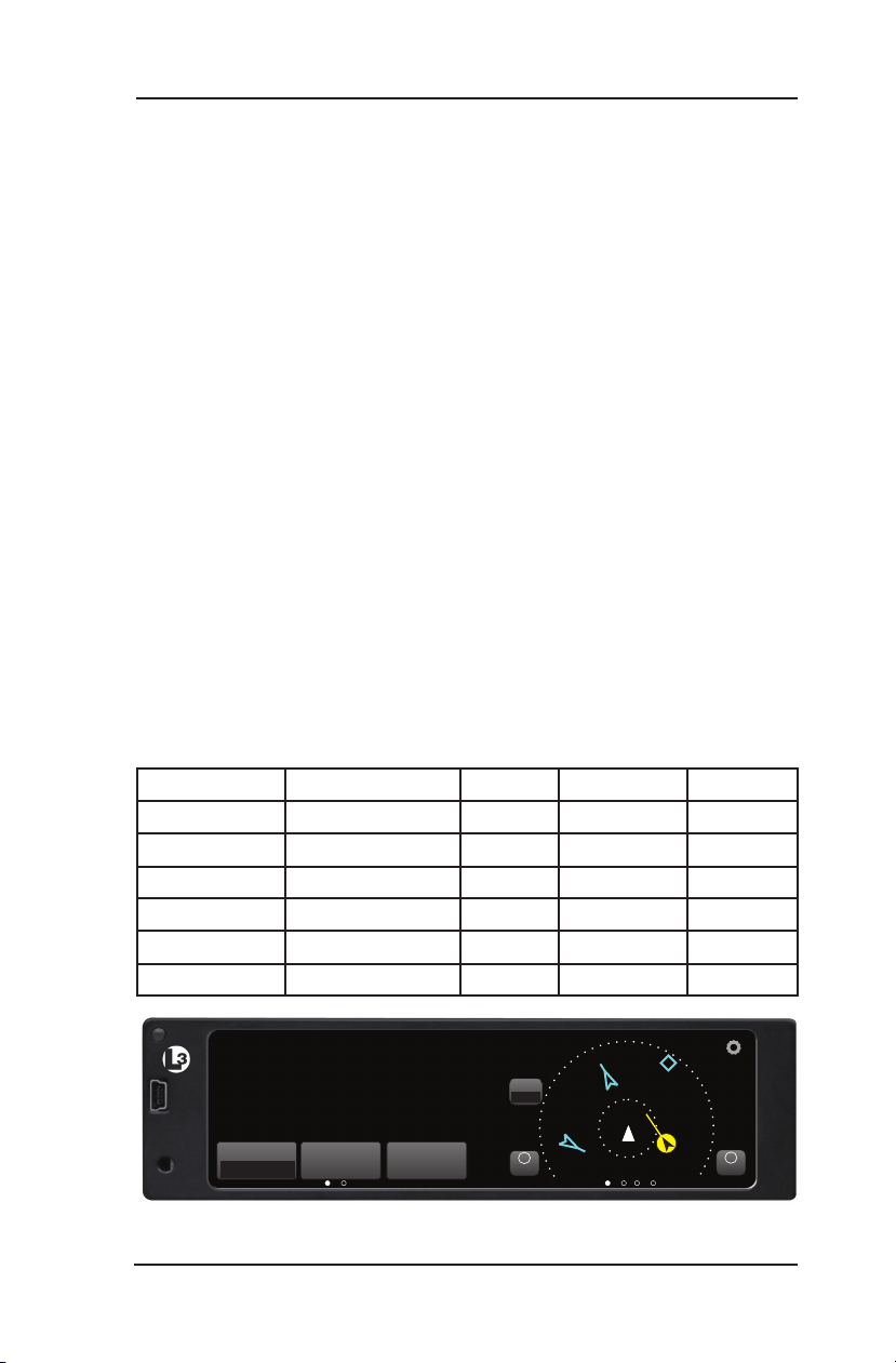
The panel mounted version of the Lynx NGT-9000 has a multifunction
touch screen display that allows the user to view transponder, traffic,
and weather information. The touch screen provides the means to
select screen views and interface with transponder, traffic, and weather
displays. See Figure 1-1.
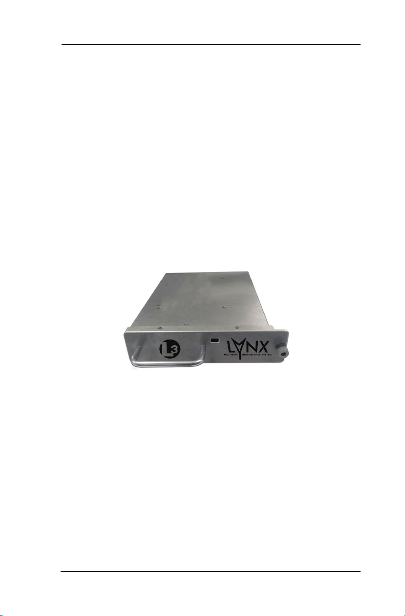
The remote version of the Lynx NGT-9000 provides the same
functionality as the panel mount, but is controlled using a compatible
alternate display or controller. See Figure 1-2.
In addition to ADS-B surveillance, some models of the Lynx
NGT-9000 include an Active Traffic Awareness System (TAS) as well
as support for antenna diversity. Table 1-1 provides model and part
number information.
Table 1-1: Model Options
Model Part nuMber taS diverSity reMote
NGT-9000 9029000-20000 No No No
NGT-9000+ 9029000-20000 Yes No No
NGT-9000D 9029000-20000 No Yes No
NGT-9000R 9029000-40000 No No Yes
NGT-9000R+ 9029000-40000 Yes No Yes
NGT-9000RD 9029000-40000 No Yes Yes
Figure 1-1: Example of Panel Mount Lynx NGT-9000

Lynx ® NGT-9000
Pilot’s Guide1-2
Description
SPECIFICATIONS
Part Number: 9029000-20000 (panel mount)
Size: Fits into a standard MARK 6.25 in width panel.
Weight: 2.96 Lbs Nominal.
Power
Requirements:
Display
Luminance:
Start Up Time On Ground 20 seconds or less
Built In Test: Fault Monitoring on all stages of operation from
Interfaces: ARINC 429, RS-422, RS-232, Discrete In-
Functionality: Mode S Transponder (1030/1090)
Service Life: Unlimited.
Scheduled
Maintenance:
+14.0 VDC nominal or +28.0 VDC nominal.
19.0 watts nominal, 24.0 watts maximum
Range 0.05 fl to 150 fl
In air 5 seconds or less.
start up to power down.
put/Outputs, RF Suppression Bus, and DCM
serial interface .
•
Global Positioning System (GPS)
•
ADS-B Receive: (1090ES/UAT)
•
ADS-B Transmit: (1090ES)
•
TIS-B (1090ES)
•
FIS-B (UAT)
•
Mode S Transponder Diversity (optional)
•
(1090ES)
Traffic Awareness System (TAS) (optional)
•
The Lynx NGT-9000 is a transponder device and
must be tested and inspected every 24 months
subject to the requirements of FAA documents
91.413.
Repairs: Repairs performed at the FAA certificated Re-
pair Station co-located at the OEM (equipment)
facility.
Compliance: The Lynx NGT-9000 has been shown to meet
the requirements in TSO-C166b and meets the
requirements of 14 CFR 91.225a installed in
accordance with these installation instructions.

Lynx ® NGT-9000
Pilot’s Guide 1-3
Description
SPECIFICATIONS
Part Number: 9029000-40000 (remote mount)
Weight: 2.75 Lbs Nominal.
Power
Requirements:
Start Up Time On Ground 20 seconds or less
Built In Test: Fault Monitoring on all stages of operation
Interfaces: ARINC 429, RS-422, RS-232, Discrete In-
Functionality: Mode S Transponder (1030/1090)
Service Life: Unlimited.
Scheduled
Maintenance:
+14.0 VDC nominal or +28.0 VDC nominal.
17.0 watts nominal, 24.0 watts maximum
In air 5 seconds or less.
from start up to power down.
put/Outputs, RF Suppression Bus, and DCM
serial interface .
•
Global Positioning System (GPS)
•
ADS-B Receive: (1090ES/UAT)
•
ADS-B Transmit: (1090ES)
•
TIS-B (1090ES)
•
FIS-B (UAT)
•
Mode S Transponder Diversity (optional)
•
(1090ES)
Traffic Awareness System (TAS) (optional)
•
The Lynx NGT-9000 is a transponder device
and must be tested and inspected every 24
months subject to the requirements of FAA
documents 91.413.
Repairs: Repairs performed at the FAA certificated
Repair Station co-located at the OEM (equipment) facility.
Compliance: The Lynx NGT-9000 has been shown to meet
the requirements in TSO-C166b and meets
the requirements of 14 CFR 91.225b installed
in accordance with these installation instructions.

Lynx ® NGT-9000
Pilot’s Guide1-4
Description
PILOT ADVISORY
The display of ADS-B data only supplements and does not replace
any operational procedure. All pilots/operators are reminded that the
airborne equipment that displays traffic is only for pilot situational
awareness. This equipment is not approved as a collision avoidance
tool and does NOT relieve the pilot of responsibility to “see-and-avoid”
other aircraft. Any deviation from an air traffic control clearance based
on cockpit information must be approved by the controlling ATC facility
prior to commencing the maneuver. Uncoordinated deviations may
place an aircraft in close proximity to other aircraft under ATC control
not seen on the airborne equipment and may possibly result in the
issuance of a pilot deviation.
•
You may receive an intermittent TIS-B aircraft display of your
aircraft, typically when you are maneuvering (e.g., climbing turn)
- due to the radar not tracking you as quickly as ADS-B does.
•
The TIS-B position update is approximately 3-13 seconds depending
on the radar coverage in which you are flying. The update rate for
ADS-B is approximately every second.
•
The TIS-B system currently only sees transponder equipped
aircraft. No transponder = no TIS-B other aircraft. Always look
outside.
•
Pilots flying in visual meteorological conditions (VMC) are reminded
that visual contact remains the only means of self separation. There
is currently no indication provided when you are operating inside
(or outside) the TIS-B Service Volume, therefore it is difficult to
know when you should be receiving all traffic information – assume
you are not.
•
Information shown on the display is provided to the pilot as an aid
to visually acquiring traffic. When under ATC control pilots should
maneuver their aircraft based only on ATC guidance or positive
visual acquisition of the conflicting traffic. Maneuver should be
consistent with ATC instructions. ATC should be contacted for
resolution of the traffic conflict.
•
The transponder signal must be transmitting during all flight
operations. It may be turned OFF only if the system is inoperable
or if advised by ATC to disable ADS-B.
•
An invalid input to the NGT-9000 may not stop operation, but may
degrade performance. Invalidities may self correct depending on
the issue.
•
Other aircraft may not be displayed if the integrity of the data being
received from ADS-B, ADS-R, or TIS-B is not sufficient to create an
accurate target on the display.
Lynx ® NGT-9000
Pilot’s Guide 1-5
Description
FUNCTIONAL DESCRIPTION
The panel mount versions of the Lynx NGT-9000 can display and
control the following information:
Flight ID or aircraft Tail Number
•
Transponder (MODE S) and Traffic Mode of Operation
•
Derived Altitude Data
•
ADS-B On/Off status
•
VFR Select and Squawk Code Input
•
IDENT
•
Traffic (graphic and textual)
•
Weather (graphic and textual)
•
TAS Mode (model specific)
•
The remote mount versions of the Lynx NGT-9000 provides the same
functionality as the panel mount, but is controlled using a CP-2500
Control Panel. Display information is shown on a optional compatible
display or PED. See Figure 1-2.
Figure 1-2: Example of Remote Mount Lynx NGT-9000
The Lynx NGT-9000 replies to Mode A, Mode C and Mode S
interrogations on 1030 MHz and transmitting responses at 1090
MHz.
Ground stations can interrogate Mode S Transponders individually
using a 24-bit ICAO Mode S address, which is unique to the particular
aircraft. In addition, ground stations may interrogate the unit for its
transponder data capability and the aircraft’s Flight ID.
Models with the TAS option provide TAS traffic advisories and a voice
audio output that announces Traffic Advisories and relative altitude.
The unit has multiple transmit/receive ARINC 429, RS-422 and RS232 data ports used to transmit data to traffic, weather, and PED
displays.

Lynx ® NGT-9000
Pilot’s Guide1-6
Description
The unit provides the transponder code, reply symbol and mode of
operation to the display.
The ADS-B provides own aircraft data with Enhanced Visual Acquisition
(EVAcq) traffic information that improves situational awareness
and flight safety by providing aircraft position, velocity, and heading
information that is automatically transmitted to other aircraft and
ground stations providing immediate surveillance of air-to-air traffic.
The 1090ES and UAT ADS-B data link have the following capabilities
1090 In - Receives ADS-B, ADS-R and TIS-B
•
1090ES Out - Transmit ADS-B
•
UAT In - Receives ADS-B, FIS-B, ADS-R, TIS-B
•
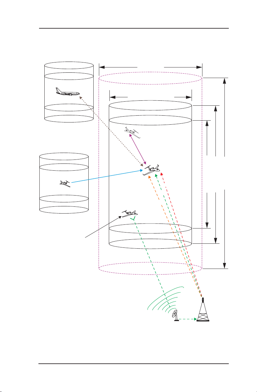
A description of these functions are provided below. A composite of
UAT / 1090ES traffic (UAT, 1090ES, ADS-R, and TIS-B) is provided
in Figure 1-3.
Model Options
The Traffic Awareness System (TAS) option provides the system
the capability to interrogate nearby aircraft transponders and issue
Traffic Advisory (TA) alert to the flight crew. This option requires the
installation of a directional antenna.
The Diversity option offers enhanced traffic awareness via 1090MHz
using the ADS-B service. This option requires the installation of an
additional top mounted UAT (L-Band) antenna.
Automatic Dependent Surveillance - Broadcast (ADS-B)
ADS-B improves situational awareness and flight safety by providing
real time traffic information. The ADS-B In function is used to receive
ground station supported TIS-B and ADS-R traffic, and direct
communication with nearby like equipped aircraft (with Mode S or
UAT) using ADS-B Out. The ADS-B Out (1090ES) function is used
to periodically broadcast (without interrogation) information about the
aircraft that includes aircraft identification, position, altitude, velocity
and other aircraft status information.
ADS-B is NOT intended to be used as a collision avoidance system
•
and does NOT relieve the pilot of responsibility to “see-and-avoid”
other aircraft.
No avoidance maneuvers are provided for, nor authorized, as a
•
direct result of a ADS-B other aircraft being displayed in the cockpit.
Avoidance maneuvers must be based on visually acquiring the
target

Lynx ® NGT-9000
Pilot’s Guide 1-7
Description
The traffic display shows the relative position of ADS-B or standard
•
traffic using text, shapes, and colors. ADS-B also provides similar
information on ADS-B equipped ground vehicles.
The effective surveillance range is 60 nmi. The passive-mode
•
surveillance range is 160 nmi and maintains report messages
for a minimum of 200 1090ES ADS-B participants and 300 UAT
ADS-B participants simultaneously. To reduce display clutter a
set number of other aircraft of the highest priority other aircraft
are displayed at a time.
Automatic Dependent Surveillance – Re-broadcast (ADS-R)
ADS-R is a ground based broadcast service that repeats ADS-B
messages from one link (1090 MHz or 978 MHz) to the other link for
aircraft with ADS-B In.
ADS-R is NOT intended to be used as a collision avoidance system
•
and does NOT relieve the pilot of responsibility to “see-and-avoid”
other aircraft.
No avoidance maneuvers are provided for, nor authorized, as a
•
direct result of a ADS-R other aircraft being displayed in the cockpit.
Avoidance maneuvers must be based on visually acquiring the
target.
The actual availability of services depends upon both the availability
•
of a ground station to support ADS-R source data and aircraft being
within range of the ground station.
ADS-R transmissions are updated at least every 2 seconds on the
•
surface, 5 seconds in the terminal area, and 10 seconds in the enroute airspace.
Other aircraft are provided by the ground station if within a 15 nm
•
horizontal range and +/-5,000 ft of altitude of the receiving aircraft.
ADS-B equipped ground aircraft and vehicles are not displayed to
airborne aircraft.
An aircraft on the ground receiving ADS-R is provided both ground
•
aircraft and vehicles as well as airborne other aircraft within 5nm
and 2,000 ft above ground level of the airport reference point.

Lynx ® NGT-9000
Pilot’s Guide1-8
Description
Traffic Information Service - Broadcast (TIS-B)
Traffic Information Service Broadcast (TIS-B) is a ground based
broadcast service that provides secondary surveillance radar (SSR)
derived traffic data (ATC transponder equipped aircraft not equipped
with ADS-B Out capability) to ADS-B In equipped aircraft.
The actual availability of services depends upon the availability of
•
ground-based radar to support TIS-B source data.
Receiving aircraft must be in both ATC radar coverage and ground
•
based transceiver (GBT) coverage in a given area to receive
TIS-B service in that area. When ownship is above 24,000 ft, the
ground station will no longer provide TIS-B service. (Targets will
be provided up to 27,500 ft) To reduce display clutter, the TIS-B
service provides traffic information on other aircraft within 15 nmi
and +/- 3500 ft of ownship.
Other aircraft are provided by the ground station if within a 15nm
•
horizontal range and +/-3,500 ft of altitude of the receiving aircraft.
ADS-B equipped ground aircraft and vehicles are not displayed to
airborne aircraft.
Aircraft not equipped with a transponder, or equipped with a Mode
•
A only transponder are not part of the TIS-B data and will not be
seen on the traffic display.
The ground station will not provide display information for Mode
•
C and Mode S transponder equipped aircraft that do not provide
altitude information.
An aircraft on the ground receiving TIS-B is provided both ground
•
aircraft and vehicles as well as airborne other aircraft within 5nm
and 2,000 ft above ground level of the airport reference point.
The TIS-B service is intended to improve the pilot’s ability to visually
•
see traffic in the air and on the airport surface so that pilots can
more effectively apply traditional “see-and-avoid” techniques.
TIS-B is NOT intended to be used as a collision avoidance system
•
and does NOT relieve the pilot of responsibility to “see-and-avoid”
other aircraft.
No avoidance maneuvers are provided for, nor authorized, as a
•
direct result of a TIS-B other aircraft being displayed in the cockpit.
Avoidance maneuvers must be based on visually acquiring the
target.
Lynx ® NGT-9000
Pilot’s Guide 1-9
Description
70 nm ( )TAS
+/- 10000 (T
AS)
+/- 3500 ft (TIS-B)
Own Aircraft
UAT / 1090ES
TAS (model option)
+/- 5000 (ADS-R)
30 nm ( / )TIS-B ADS-R
ATC - Ground Station
Other Aircraft
UAT Non-Equipped
Mode A/C Equipped
TIS-B
Other Aircraft UAT
FIS-B
TIS-B
Other Aircraft
TAS
Other Aircraft 1090ES
ADS-R
Figure 1-3: Example of Own Aircraft UAT, 1090ES, & TAS Traffic

Lynx ® NGT-9000
Pilot’s Guide1-10
Description
Traffic Awareness System (TAS)
The TAS option is available with model NGT-9000+ and NGT9000R+. TAS is an active system that operates as an aircraft-toaircraft interrogation device. The unit interrogates transponders in the
surrounding airspace similar to ground based radar; with an effective
active-mode surveillance range of 35 nmi. When replies to these
active interrogations are received, the responding aircraft’s range,
altitude, and closure rates are computed to plot traffic location and
predict collision threats. The NGT-9000+ or NGT-9000R+ alerts the
flight crew to nearby transponder equipped aircraft and assists the
pilot in the visual acquisition of aircraft that may represent a danger.
Traffic information, out to a selected range, is graphically displayed on
the NGT-9000+ or alternate display.
The system display shows the relative position of traffic using text,
•
shapes (i.e., Traffic Advisory = solid circle; Other Traffic = open
diamond, Proximate Traffic = solid diamond) and colors.
The effective active-mode surveillance range is 35 nmi and
•
track 35 ATCRBS intruders simultaneously with the other aircraft
bearing relative to the nose of own aircraft.
The tracking of other aircraft is in a cylindrical volume centered
•
on own aircraft with a maximum radius of 35 nmi and extending
10,000 ft above and 10,000 ft below own aircraft.
The system uses a voice audio output that announces Traffic
•
Advisory and relative altitude.
Refer to Chapter 4 Principles of TAS Operation for more information.

Lynx ® NGT-9000
Pilot’s Guide 1-11
Description
Flight Information Service - Broadcast (FIS-B)
FIS-B is a FAA ground based broadcast service providing graphical
and textual display of weather and aeronautical information. Table 1-1
provides a description of the various products available via the FIS-B
broadcast.
The broadcast includes Airmen’s Meteorological Information
(AIRMET), Significant Meteorological Information (SIGMET), Aviation
Routine Weather Report (METAR), Regional and Next-Generation
Radar (NEXRAD), display of CONUS radar information, Notices
to Airmen (NOTAM), Terminal Aerodrome Forecast (TAF), Winds
and Temperatures Aloft, TIS-B Service Status, Temporary Flight
Restrictions (TFR) and Aviation Special Selected Weather (SPECI).
FIS-B information is to be used for pilot planning decisions and pilot
near-term decisions focused on avoiding areas of inclement weather
that are beyond visual range or where poor visibility precludes visual
acquisition of inclement weather. FIS-B weather and National Airspace
System (NAS) status information may be used as follows:
To promote pilot awareness of ownship location with respect to
•
reported weather, including hazardous meteorological conditions,
NAS status indicators, and enhance pilot planning decisions and
pilot near-term decision-making.
To cue the pilot to communicate with the Air Traffic Control
•
controller, Flight Service Station specialist, operator dispatch, or
airline operations control center for general and mission critical
meteorological information, NAS status conditions, or both.
FIS-B information including weather information, NOTAMs, and TFR
areas are intended for the sole purpose of assisting in long- and nearterm planning decision making. The system lacks sufficient resolution
and updating capability necessary for aerial maneuvering associated
with immediate decisions.

Lynx ® NGT-9000
Pilot’s Guide1-12
Description
Table 1-2: Description of FIS-B Available Information
Product deScriPtion
AIRMET Airmen’s Meteorological Information is a weather ad-
visory issued by a meteorological watch office a potentially hazardous condition exists for low-level aircraft and/or aircraft with limited capability. Compared
to SIGMETs, AIRMETs cover less severe weather:
moderate turbulence and icing, surface winds of 30
knots, or widespread restricted visibility.
METAR Aviation routine weather report is a format for report-
ing weather information. METARs are predominantly
used by pilots in fulfillment of a pre-flight weather
briefing. METARs typically come from airports or permanent weather observation stations.
NEXRAD,
Regional
Next-Generation Radar is a nationwide network of
high resolution Doppler weather radars, which detect
precipitation and atmospheric movement or wind. It
returns data which when processed can be displayed
in a mosaic map which shows patterns of precipitation and its movement. The “Regional NEXRAD” FISB product is a composite of available NEXRAD radar
imagery in a local area, showing a more detailed image than the “CONUS NEXRAD” product.
NEXRAD,
CONUS
NOTAM Notice To Airmen is created and transmitted by gov-
SIGMET Significant Meteorological Information is a concise
The “CONUS NEXRAD” FIS-B product is a summary composite of available NEXRAD radar imagery
across the 48 states.
ernment agencies under guidelines specified by
Annex 15: Aeronautical Information Services of the
Convention on International Civil Aviation. A NOTAM
is filed with an aviation authority to alert aircraft pilots
of any hazards En Route or at a specific location.
The FIS-B NOTAM product consists of NOTAM-Ds
and NOTAM-FDCs (including TFRs).
description of the occurrence or expected occurrence
of specified En Route weather phenomena which
may affect the safety of aircraft operations. SIGMETs
are intended for dissemination to all pilots in flight to
enhance safety.

Lynx ® NGT-9000
Pilot’s Guide 1-13
Description
Table 1-2: Description of FIS-B Available Information (continued)
Product deScriPtion
SIGMET,
Convective
TAF Terminal Aerodrome Forecast is a format for report-
Winds and
Temperatures Aloft
A Convective SIGMET will be issued when the following conditions are occurring or, in the judgment of
the forecaster, are expected to occur:
a. A line of thunderstorms at least 60 miles long with
thunderstorms affecting at least 40 percent of its
length.
b. An area of active thunderstorms affecting at least
3,000 square miles covering at least 40 percent of
the area concerned and exhibiting a very strong
radar reflectivity intensity or a significant satellite
or lightning signature.
c. Embedded or severe thunderstorm (s) expected
to occur for more than 30 minutes during the valid
period regardless of the size of the area.
ing aviation weather forecast information. Generally
a TAF is a 9- or 12-hour forecast, though some TAFs
can cover an 18- or 24-hour period. TAFs complement and use similar encoding to METAR reports.
They are produced by a human forecaster based on
the ground. For this reason there are fewer TAF locations than there are METARs. TAFs can be more
accurate than Numerical Weather Forecasts, since
they take into account local, smallscale, geographic
effects.
Winds and Temperature Aloft Forecast is forecast for
specific atmospheric conditions in terms of wind and
temperature in a specific altitude measured mostly in
feet (ft) above mean sea level (MSL). The forecast is
specifically used for aviation purposes.

Lynx ® NGT-9000
Pilot’s Guide1-14
Description
EQUIPMENT DESCRIPTION
The Lynx NGT-9000 MSS family consists of the following standard and
optional equipment. Refer to the Aircraft Flight Manual Supplement to
determine what optional equipment is installed. Chapter 3 provides a
list of optional cockpit switches and lamps.
Required Equipment
GPS Antenna
•
L-Band (978MHz/1030/MHz/1090MHz) Antenna
•
Detachable Configuration Module (DCM)
•
Optional Equipment
Directional Antenna (required for TAS operation)
•
Additional L-Band Antenna (required for diversity operation)
•
Traffic Display
•
Weather Display
•
WiFi Serial Adapter and Personal Electronic Device (PED)
•
CP-2500 Control Panel (Required for the remote mount version)
•
GPS Antenna and Internal GPS Receiver
The GPS utilizes signals from Global Positioning System (GPS)
satellite constellation and Satellite-Based Augmentation Systems
(SBAS). The Lynx NGT-9000 have an internal GPS function that
provides position, velocity, time and integrity (NIC, NAC etc) information to the ADS-B functions. The antenna is located on the top of the
aircraft.
L-Band Antenna
The L-Band antenna is used by the Lynx NGT-9000 to receive
1030MHz, receive and transmit 1090MHz and receive 978MHz. It is
located on the bottom of the aircraft.
A second L-Band antenna is installed on the top of the aircraft for
models with Diversity.
Detachable Configuration Module (DCM)
The DCM is a solid-state device that retains software and hardware
configuration information. It is permanently attached to the aircraft
via the wiring harness and communicates with Lynx NGT-9000 via
serial bus. Configuration options are set up during installation. The
configuration data that is saved on the DCM are as follows: DCM
configuration version, configuration, input / output interface options,
aircraft specific options, and installation calibration parameters.

Lynx ® NGT-9000
Pilot’s Guide 1-15
Description
Directional Antenna
A directional antenna is used to receive 1090MHz and transmit
1030MHz for models with TAS.
Alternate Displays
Screen information may look different on displays interfaced with the
Lynx NGT-9000. Refer to that display’s manual for a description of
how information is depicted.
The operation and display features provided in this Pilot’s Guide are
specific to the information depicted on the Lynx NGT-9000.
Personal Electronic Device (PED)
The Lynx NGT-9000 supports the use of personal electronic devices
(e.g., tablets) via a WiFi connection. The PED must use compatible
applications that support the ADS-B broadcast services (i.e., ADSB In, TIS-B, ADS-R, and FIS-B). Check with an avionics dealer
or contact L-3 Avionics Systems for a current list of compatible
applications.
WiFi Serial Adapter
This device provides a WiFi connection between the Lynx NGT-9000
and the PED. It is permanently attached to the aircraft via the wiring
harness.
CP-2500 Control Panel
The CP-2500 is a control panel offered by L-3 Avionics Systems. It
is the only compatible control panel for the remote mount Lynx NGT-
9000. The operational information provided in this guide is limited.
Refer to the CP-2500 Pilot’s Guide (0040-17250-01) for detailed
information.

Lynx ® NGT-9000
Pilot’s Guide1-16
Description
Page intentionally blank

Lynx ® NGT-9000
Pilot’s Guide 2-1
Operation
CHAPTER 2
OPERATION
INTRODUCTION
This chapter describes preflight procedures for the panel and remote
mount Lynx NGT-9000. Operational information in this chapter is
specific to the panel mount Lynx NGT-9000.
Refer to Chapter 3 (Controls and Indicators) for operation information
for installations with a CP-2500 Control Panel or compatible display.
POWER (REMOTE MOUNT)
There is no power on/off switch for the remote mount version of the
1.
Lynx NGT-9000. Depending on the aircraft, use either the battery
switches or avionics master switch to apply power.
Normal operation begins within 10 seconds of applying power.
2.
During start up the unit checks for valid configuration data and
initializes self tests.
The GPS begins initializing.
3.
If installed the CP-2500 shows GPS INIT while the GPS is
a.
initializing.
If an ADS-B System Fail is displayed after 2 minutes, then
•
the GPS position was not acquired. If the ADS-B System Fail
is displayed in less than 2 minutes then a different problem
has been detected.
Cycle power to the Lynx NGT-9000 to restart GPS initialization.
•
If the problem continues, refer to the troubleshooting section
for possible corrective actions.
b. If installed the ADS-B Out Fail lamp flashes (1 second On/Off)
while the GPS is initializing. Lamp continues flashing until
GPS position is acquired.

Lynx ® NGT-9000
Pilot’s Guide2-2
Operation
NORMAL OPERATION (REMOTE MOUNT)
Operational control of the remote mount version of the Lynx NGT9000 is accomplished with a CP-2500 Control Panel. An ADS-B Out
Fail lamp (if installed) can provide system status.
Operation and control information for the CP-2500 Control Panel is
found in Chapter 3 (Controls and Indicators) or in the CP-2500 Pilot’s
Guide (0040-17250-01).
POWER (PANEL MOUNT)
There is no power on/off switch on the panel mount version of the Lynx
NGT-9000. Depending on the aircraft, use either the battery switches
or avionics master switch to apply power. After power is applied the
unit begins initialization and self-tests begin. When on ground the unit
cycles through the following screen sequence:
Splash
•
System Status / Version
•
Flight ID (optional)
•
Normal Operation
•
When in air and power is cycled the unit transitions to normal
operation within 5 seconds, bypassing the splash, version and flight
ID screens.
Splash Screen
The splash screen is displayed in less than 5 seconds after power is
applied. The company name/Logo is shown on the left side and the
product name on the right. See Figure 2-1.
Figure 2-1: Example of Splash Screen

Lynx ® NGT-9000
Pilot’s Guide 2-3
Operation
System Status
System Pass
Power On Result:
Versions
Flight Sw: 0000-00000-XXYZ
GPS/UAT RX: _ _ _ _ _ _ _
Airport DB: YYYYMMDD
Map DB: YYYYMMDD
System Status / Versions Screen
The system status is shown on the left screen and should show
“System Pass” in green text. The version screen is located on the
right side and shows the software and database version information.
See Figure 2-2.
Figure 2-2: Example of System Status / Version Screens
If System Status is “System Fail”, then the message “Self-Test
•
Failures Occurred” is shown on the right side of the display and the
“System Test Failed” is heard through the aircraft audio system.
The option to restart the unit or to continue start up in a degraded
mode is shown on the right side of the display
Tap the Restart button to restart the system.
•
If the “System Fail” message continues to be seen tap the
•
Continue button to proceed. Refer to Chap. 5 (Troubleshooting)
for corrective actions.
If System Status is “System Degraded”, then the message “See
•
Msg Window” is shown on the right side of the display.
Tap Continue button to proceed. Refer to Chap. 5 (Troubleshooting)
•
for corrective actions.
 Loading...