

Page 1

viation Products
Pilot’s Guide for Models
NGT-9000
NGT-9000+
NGT-9000D
NGT-9000D+
NGT-9000R
NGT-9000R+
NGT-9000RD
NGT-9000RD+
A
Page 2

Page 3

Document Precedence
This Pilot’s Guide provides general information about the operation
of the NGT-9000. Refer to your FAA-approved Airplane Flight Manual
(AFM) and its ight manual supplements for information specic to
your aircraft. If there is conicting information between the AFM and
this guide, the AFM takes precedence over this guide.
Disclaimer
The term “Lynx NGT-9000” when used in this Pilot’s Guide
encompasses all models unless otherwise stated.
This Pilot’s Guide is subject to change without notice. The illustrations
in this guide are typical for the Lynx NGT-9000.
Screen information may look different on displays interfaced with
the Lynx NGT-9000. Refer to the pilot’s guide for that display for a
description of how information is depicted.
The installation of ADS-B In avionics provides the pilot with
supplemental information and does not replace a pilot’s see-andavoid responsibility. This equipment is not approved as a collision
avoidance tool. Any deviation from an air trafc control clearance
based on cockpit information must be approved by the controlling ATC
facility prior to commencing the maneuver. Uncoordinated deviations
may place an aircraft in close proximity to other aircraft under ATC
control not seen on the airborne equipment and may possibly result in
the issuance of a pilot deviation.
ADS-B is currently being deployed throughout the National Airspace
System (NAS). The availability of U.S. ground based transceivers
(GBT) is limited in selected areas. For information regarding the
FAA’s system of ADS-B, TIS-B, ADS-R, and FIS-B refer to the FAA’s
Aeronautical Information Manual sections 4-5-7 to 4-5-10.
Revision Highlights
Incorporate software release 2.1 for Lightning Detection, transponder
standby mode using discrete switch options, squawk VFR disable
button, and option to display terrain without alerts.
Pilot’s Guide i
Page 4

Pilot’s Guide
Methods and apparatus disclosed and described herein have
been developed solely on company funds. No government or other
contractual support or relationship whatsoever has existed which
in any way affects or mitigates proprietary rights of ACSS® in these
developments. Methods and apparatus disclosed herein may be
subject to U.S. Patents existing or applied for. ACSS® reserves the right
to add, improve, modify, or withdraw functions, design modications,
or products at any time without notice.
Export Notice
This document consists of general capabilities information
that is not dened as controlled technical data under Export
Administration Regulations (EAR) Part 772.
Product Part No.
9029000-20000 (panel mount)
9029000-40000 (remote mount)
Document Part No.
0040-17000-01 (Revision H)
© Copyright 2016
ACSS
Refer to the following for additional copyright information:
https://www.l-3avionics.com/open-source.aspx
https://www.l-3avionics.com/customer-support/
ight-data-info/open-source-software-report.aspx
®
Trademarks
Lynx ® is a registered trademark of L-3 Avionics Systems
The NGT-9000 is covered by one or more of the following
patents: 9,285,472, 8,736,465. Other patents pending
Distributed with permission by:
L-3 Avionics Systems.
5353 52nd Street, S.E.
Grand Rapids, MI 49512 USA
Customer Support (800) 453-0288
International (616) 949-6600
Avionics Systems
FAX (616) 977-6898
www.L-3avionics.com
Pilot’s Guideii
Page 5

Table of Contents
Chapter 1: Description
Introduction ..................................................................................................1-1
Functional Description .................................................................................1-2
Transponder ............................................................................................ 1-3
Transponder Diversity Options ............................................................... 1-3
ADS-B System ........................................................................................ 1-3
Trafc Display ......................................................................................... 1-4
Trafc Advisory System (TAS) ................................................................ 1-4
ADS-B Trafc Advisory System (ATAS) .................................................. 1-4
Weather Display ...................................................................................... 1-5
Trafc and Weather Output Interfaces .................................................... 1-5
Built-In Test and Operational Status ....................................................... 1-5
Terrain Awareness and Warning System (TAWS) ................................... 1-5
Equipment Description ................................................................................1-7
Required Equipment ............................................................................... 1-7
Optional Equipment ................................................................................ 1-7
GPS Antenna and Internal GPS Receiver .............................................. 1-7
L-Band Antenna ...................................................................................... 1-7
Detachable Conguration Module (DCM) ............................................... 1-7
Directional Antenna ................................................................................. 1-8
Alternate Displays ................................................................................... 1-8
Personal Electronic Device (PED) .......................................................... 1-8
WiFi Serial Adapter ................................................................................. 1-8
CP-2500 Control Panel ........................................................................... 1-8
Chapter 2: Operation - Panel Mount
Introduction ..................................................................................................2-1
Pilot Advisory ...............................................................................................2-1
Power On.....................................................................................................2-2
Splash Screen......................................................................................... 2-2
System Status / Versions Screen............................................................ 2-3
Flight ID Screen (optional) ...................................................................... 2-4
Normal Operation.................................................................................... 2-4
Basic Operation ...........................................................................................2-5
Screen Buttons ....................................................................................... 2-5
Application Screens ................................................................................ 2-7
Transponder Operation ...............................................................................2-9
Squawk Code.......................................................................................... 2-9
Current Pressure Altitude ...................................................................... 2-10
Pilot’s Guide iii
Page 6

Table of Contents (continued)
Flight ID / Call Sign ............................................................................... 2-10
Mode Control ........................................................................................ 2-10
Transponder Reply ............................................................................... 2-10
IDENT Button ........................................................................................ 2-10
Squawk VFR Button...............................................................................2-11
MSG Button ...........................................................................................2-11
ON-GND Indicator..................................................................................2-11
System Test Button ................................................................................2-11
Trafc Operation ........................................................................................2-13
Limitations ............................................................................................. 2-13
Trafc Advisory ..................................................................................... 2-13
Trafc Screen ........................................................................................ 2-14
Ownship Symbol .................................................................................. 2-15
Trafc Symbols ..................................................................................... 2-15
Trafc Display Priority ........................................................................2-18
Trafc Altitude Mode ............................................................................. 2-18
Zoom Buttons........................................................................................ 2-18
Range Rings ......................................................................................... 2-19
TFC Button............................................................................................ 2-19
Transponder Banner ............................................................................. 2-20
Trafc Mode Indicator ........................................................................... 2-20
MSG Button .......................................................................................... 2-20
Trafc Options Button ........................................................................... 2-21
Trafc Options Screen ........................................................................2-21
Options - Status..................................................................................2-21
Options - Settings ...............................................................................2-22
Acknowledge Button ............................................................................. 2-23
Selected Trafc Info Button (i)............................................................... 2-23
TIS-B No Coverage Indicator ................................................................ 2-23
Trafc Information Window ................................................................... 2-24
Selected Trafc ID................................................................................. 2-24
Selected Trafc GS ............................................................................... 2-25
True Track (TRK) .................................................................................. 2-25
Aural Announcements ...............................................................................2-25
Extended Audio Callouts ....................................................................... 2-26
Audio Inhibit .......................................................................................... 2-26
Details on Trafc Operation .......................................................................2-27
Automatic Dependent Surveillance - Broadcast (ADS-B) ..................... 2-27
Pilot’s Guideiv
Page 7

Table of Contents (continued)
Automatic Dependent Surveillance – Re-broadcast (ADS-R)............... 2-28
Trafc Information Service - Broadcast (TIS-B) .................................... 2-29
Trafc Advisory Systems ...........................................................................2-30
ADS-B Trafc Advisory System (ATAS) ................................................ 2-31
Trafc Advisory System (TAS) .............................................................. 2-31
TAS Sensitivity Levels ........................................................................2-32
Sensitivity Level A ...........................................................................2-32
Sensitivity Level B...........................................................................2-32
Other Aircraft Ground Filtering ...........................................................2-35
Interference Limiting ...........................................................................2-35
Weather Operation ....................................................................................2-36
Details on Flight Information Service - Broadcast (FIS-B) .................... 2-36
FIS-B No Coverage Indicator ................................................................ 2-39
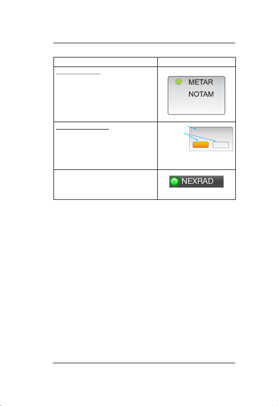
FIS-B Graphical Weather Application ................................................... 2-40
Map Elements ....................................................................................2-40
Information Button (i) ..........................................................................2-41
TFR Map Elements .........................................................................2-41
AIRMET and SIGMET Map Elements ............................................2-41
METAR .........................................................................................2-43
NEXRAD Map Elements .................................................................2-43
CONUS Map Elements ...................................................................2-43
Trafc Button ......................................................................................2-44
Zoom Buttons .....................................................................................2-44
Display Range Indicator .....................................................................2-44
Panning ..............................................................................................2-44
North Indicator ....................................................................................2-44
Airport ID Indicator .............................................................................2-44
Orientation Button ..............................................................................2-44
Map Options Button............................................................................2-45
On/Off Option Screen .........................................................................2-45
Weather Map Legend Screen .........................................................2-45
Banner .........................................................................................2-45
Display Area....................................................................................2-47
Declutter Option Screen .................................................................2-47
Weather Map Text Screen .................................................................. 2-47
Display Area....................................................................................2-48
Banner .........................................................................................2-48
Product Select List Window ...........................................................2-48
Pilot’s Guide v
Page 8

Table of Contents (continued)
FIS-B Graphic Winds & Temp Application ............................................. 2-49
Trafc Button ......................................................................................2-49
Aloft Button .........................................................................................2-51
Panning ..............................................................................................2-51
Zoom Buttons .....................................................................................2-51
Issue Valid Time Indication .................................................................2-51
Ownship Symbol ...............................................................................2-51
North Indicator ....................................................................................2-51
Flight Level Selection .........................................................................2-51
FIS-B Textual Application ...................................................................... 2-52
Display Area .......................................................................................... 2-52
Banner ................................................................................................2-52
Trafc Button ......................................................................................2-52
Airport Button .....................................................................................2-53
Edit Airport ID Window ....................................................................2-53
Favorites Button ................................................................................2-54
Favorites Pick List Window .............................................................2-54
Product Button....................................................................................2-55
Product Pick List Window ...................................................................2-55
TAWS Operation ........................................................................................2-56
Limitations ............................................................................................. 2-57
Dening Terrain Alerts ........................................................................... 2-57
Trafc Button ......................................................................................... 2-57
Zoom Buttons........................................................................................ 2-57
Display Range Indicator ........................................................................ 2-58
Display Orientation Indicator ................................................................. 2-58
Aural Acknowledge Button .................................................................... 2-58
AGL Altitude Readout ........................................................................... 2-58
Ownship Symbol .................................................................................. 2-59
Obstacle Symbols ................................................................................. 2-59
Airport Symbols..................................................................................... 2-60
Airport Symbol Operation ...................................................................2-60
TAWS Terrain Color Legend ................................................................. 2-61
Information Button (i) ............................................................................ 2-62
TAWS Airport Text Screen ..................................................................2-62
TAWS Options Button ........................................................................... 2-63
TAWS Options Screen........................................................................2-63
TAWS Display Alerts ............................................................................. 2-63
Pilot’s Guidevi
Page 9

Table of Contents (continued)
TAWS Audio Alerts ................................................................................ 2-64
500 ft Altitude Callout. ........................................................................2-64
Conditions to Trigger Alerts or Callouts................................................. 2-65
Forward Looking Terrain Avoidance (FLTA) .......................................2-66
Reduced Required Terrain Clearance (RTC) .....................................2-67
Imminent Terrain Impact (ITI) .............................................................2-68
Premature Descent ............................................................................2-69
Ground Proximity Warning System (GPWS) Alerting .........................2-70
Excessive Descent Rate .................................................................2-70
Negative Climb Rate or Altitude Loss After Takeoff ............................ 2-71
Altitude Loss After Takeoff Graph .......................................................2-71
Altitude of 500 ft .................................................................................2-73
Lightning Operation ...................................................................................2-74
Trafc Button ......................................................................................... 2-74
Ownship Symbol ................................................................................... 2-75
Zoom Buttons........................................................................................ 2-75
360 View ............................................................................................... 2-75
120 View ............................................................................................... 2-75
Mode Button.......................................................................................... 2-76
Clear Button .......................................................................................... 2-76
Lightning Option Button ........................................................................ 2-75
Lightning Settings (View Mode, Stabilization, Status) ....................2-77
Heading Stabilization ......................................................................2-78
Strike Rate Indicator ............................................................................. 2-78
Strike Rate Trend Arrow ........................................................................ 2-78
Heading Indicator .................................................................................. 2-78
Application Indicator / Nearby Strike ..................................................... 2-78
Maintenance Mode ....................................................................................2-80
Chapter 3: Operation - Remote Mount
Introduction ..................................................................................................3-1
Power On.....................................................................................................3-1
CP-2500 Control Panel................................................................................3-2
Power Off ................................................................................................ 3-2
Enter the Squawk Code .......................................................................... 3-3
Set Operational Mode ............................................................................. 3-3
View Pressure Altitude ............................................................................ 3-4
Set Flight ID ............................................................................................ 3-4
IDENT Activation ..................................................................................... 3-4
Pilot’s Guide vii
Page 10

Table of Contents (continued)
VFR Code Select .................................................................................... 3-5
Set VFR Code ......................................................................................... 3-5
View Info ................................................................................................. 3-5
Trafc Advisory Aural Acknowledge and Reply ....................................... 3-6
Enable On Ground TAS Operation ......................................................... 3-6
TAWS Alert Aural Acknowledge .............................................................. 3-6
Inhibit TAWS Alert Message .................................................................... 3-6
Inhibit TAWS Obstacles .......................................................................... 3-7
Messages................................................................................................ 3-7
Display Messages ................................................................................... 3-8
Chapter 4: Controls and Indicators
Introduction ..................................................................................................4-1
Cockpit Switches ........................................................................................4-1
IDENT ..................................................................................................... 4-1
Audio Acknowledge................................................................................. 4-1
Indicator Lamps ...........................................................................................4-2
Trafc Advisory ............................................................................................4-2
TAWS Caution......................................................................................... 4-2
TAWS Warning ........................................................................................ 4-2
ADS-B Out Fail ....................................................................................... 4-2
Alternate Displays........................................................................................4-3
Trafc Display ......................................................................................... 4-3
Other Trafc Symbol ............................................................................4-4
Proximity Advisory Symbol ................................................................... 4-4
Ownship Symbol ..................................................................................4-4
Off-Scale Trafc Advisory (TA) ............................................................4-4
Indicators ..............................................................................................4-4
Weather Display ...................................................................................... 4-5
WiFi Interface .......................................................................................... 4-5
Compatible Control Panel ....................................................................... 4-5
Chapter 5: Troubleshooting
Introduction ..................................................................................................5-1
General Display Conditions .........................................................................5-1
System Status Messages ............................................................................5-4
Appendix A
Record Of Important Information ................................................................ A-1
Pilot’s Guideviii
Page 11

List of Illustrations
Figure 1-1: Example of Panel Mount Lynx NGT-9000 .................................1-2
Figure 1-2: Example of Remote Mount Lynx NGT-9000 .............................1-3
Figure 1-3: Example of Own Aircraft UAT, 1090ES, and TAS Trafc ...........1-6
Figure 2-1: Example of Splash Screen ........................................................2-2
Figure 2-2: Example of System Status / Version Screens ...........................2-3
Figure 2-3: Example of Flight ID Screen .....................................................2-4
Figure 2-4: Example of Normal Operation ...................................................2-4
Figure 2-5 Transponder Application Screen ................................................2-9
Figure 2-6: Squawk Code Edit Screen ...................................................... 2-11
Figure 2-7: Example of System Test Screen ............................................. 2-12
Figure 2-8: Trafc Applications Screen ......................................................2-14
Figure 2-9: Trafc Options Screen - Status ...............................................2-21
Figure 2-10: Trafc Options Screen - Settings ..........................................2-23
Figure 2-11: Example of Trafc Information Window .................................2-24
Figure 2-12: Trafc Display Mode and TAS Trafc Zone Graphic .............2-34
Figure 2-13: FIS Button .............................................................................2-39
Figure 2-14: Weather Map .........................................................................2-40
Figure 2-15: Example of NEXRAD Weather Map ......................................2-43
Figure 2-16: On/Off Options Screen ..........................................................2-45
Figure 2-17: Weather Map Legend Screen ...............................................2-46
Figure 2-18: Declutter Option Screen ........................................................2-47
Figure 2-19: Weather Map Text Screen ..................................................... 2-48
Figure 2-20: Product Pick List Window......................................................2-49
Figure 2-21: Aloft Map Screen ...................................................................2-49
Figure 2-22: Winds Aloft Map Elements ....................................................2-50
Figure 2-23: FIS-B Textual Application ......................................................2-52
Figure 2-24: Example of Edit Airport ID Window .......................................2-53
Figure 2-25: Example of Favorites Window...............................................2-54
Figure 2-26 Example of Product Pick List Window....................................2-55
Figure 2-27: TAWS Screen ........................................................................2-56
Figure 2-28: TAWS Airport Text Screen .....................................................2-62
Figure 2-29: TAWS Options Screen ..........................................................2-63
Figure 2-30: Forward Looking Terrain Avoidance (FLTA) ..........................2-66
Pilot’s Guide ix
Page 12

List of Illustrations (continued)
Figure 2-31: Phase of Flight Denitions ....................................................2-66
Figure 2-32: Reduced RTC Alert Condition ...............................................2-67
Figure 2-33: ITI Alert Condition..................................................................2-68
Figure 2-34: Premature Descent Alert Condition .......................................2-69
Figure 2-35: Excessive Descent Rate Alert Condition ...............................2-70
Figure 2-36: Excessive Descent Rate Graph ............................................2-70
Figure 2-37: Negative Climb Rate or
Altitude Loss After Takeoff Alert Condition ............................2-71
Figure 2-38 Negative Climb Rate Graph ...................................................2-72
Figure 2-39: Altitude Loss After Takeoff Graph .......................................... 2-72
Figure 2-40: Altitude of 500 Feet Callout Condition ...................................2-73
Figure 2-41: Lightning Screen 360 View ...................................................2-74
Figure 2-42: Lightning Screen 120 View ..................................................2-75
Figure 2-43: Lightning Setting Page ..........................................................2-77
Figure 2-44: Maintenance Screens ...........................................................2-75
Figure 3-1: Example of CP-2500 .................................................................3-3
List of Tables
Table 1-1: Model Options.............................................................................1-1
Table 2-1: Button Functions .........................................................................2-5
Table 2-2: Trafc Symbols .........................................................................2-17
Table 2-3: TAS Trafc Advisory Situations .................................................2-34
Table 2-4: Description of FIS-B Available Information ...............................2-38
Table 2-5: Airport Symbols.........................................................................2-43
Table 2-6: Terrain Color Scheme ............................................................... 2-62
Table 2-7: TAWS Display Alerts .................................................................2-65
Table 2-8: Caution & Warning Alert Phrases .............................................2-66
Table 2-9: Required Terrain Clearances for the
Reduced RTC Alert Condition ................................................2-68
Table 2-10: Required Terrain Clearances for the ITI Alert Condition .........2-69
Table 2-11: Lightning Symbols ...................................................................2-76
Table 5-1: General Display Conditions
for the Panel Mount Lynx NGT-9000 ..........................................5-1
Pilot’s Guidex
Page 13

List Of Abbreviations and Acronyms
° Degree
AC Advisory Circular
ABV Above
ADS-B Automatic Dependant Surveillance – Broadcast
ADS-R Automatic Dependant Surveillance – Rebroadcast
AFM Airplane Flight Manual
AGL Above Ground Level
AIRMET Airmen’s Meteorological Information
ALT Altitude
ATAS ADS-B Trafc Advisory System
ATC Air Trafc Control
ATCRBS Air Trafc Control Radar Beacon System
BLW Below
BRT Brightness
CDTI Cockpit Display of Trafc Information
CEL Cell
CLR Clear
CONUS Contiguous United States
CPA Closest Point of Approach
DCM Detachable Conguration Module
DTIF Display Trafc Information File
DO- RTCA Document
EAR Export Administration Regulations
EGPWS Enhanced Ground Proximity Warning System
EVAcq Enhanced Visual Acquisition
FAA Federal Aviation Administration
FDE Fault Detection and Exclusion
FLTA Forward Looking Terrain Avoidance
FIS-B Flight Information Service - Broadcast
Foot-Lambert
ft Feet
ft/min Feet Per Minute
GA General Aviation
GBT Ground Based Transceiver
GALT GPS Altitude
GND Ground
GPWS Ground Proximity Warning System
GPS Global Positioning System
GS Ground Speed
GPWS Ground Proximity Warning System
HAE Height Above Ellipsoid
HPL
HPLFD Horizontal Protection Level using a weighted FDE algorithm
hPa Hectopascals
Hz Hertz
ICAO International Civil Aviation Organization
ID Identication
IDENT Identication
ITI Imminent Terrain Impact
InHg Inches of Mercury
kt/kts Knot (s)
lbs pounds
max Maximum
METAR Aviation Routine Weather Report
Horizontal Protection Level Using SBAS error estimates
SBAS
Pilot’s Guide xi
Page 14

List Of Abbreviations And Acronyms (cont.)
MHz Mega Hertz
MOD Mode
MSG Message
MSS Multilink Surveillance System
NACp Navigation Accuracy Category for Position
NAR Non Altitude Reporting
NAS National Airspace System
NEXRAD Regional and Next-Generation Radar
NIC Navigation Integrity Category
NOTAM Notices to Airmen
NM or nmi Nautical Miles
NRM Normal
OT Other Trafc
PA Proximity Advisory
PALT Pressure Altitude
PED Personal Electronic Device (e.g., tablet)
PIREP Pilot Report
P/N Part Number
R Reply
RAIM Receiver Autonomous Integrity Monitoring
REF Reference
RTC Required Terrain Clearance
RTCA Radio Technical Commission for Aeronautics, Inc.
SBAS Satellite-Based Augmentation System
SIGMET Signicant Meteorological Information
SIL Source Integrity Level
SPECI Aviation Special Selected Weather
SPI Special Identication
STBY Standby
STAB Stabalization
STK Strike
SUA Special Use Airspace
SSR Secondary Surveillance Radar
TA Trafc Advisory
TAWS Terrain Awareness and Warning System
TAF Terminal Aerodrome Forecast
TAS Trafc Advisory System
TFC Trafc
TIF Trafc Information File
TRK Track
TFR Temporary Flight Restrictions
TIS-B Trafc Information Service - Broadcast
TSO Technical Standard Order
UAT Universal Access Transceiver
UNR Unrestricted
VFR Visual Flight Rules
VMC Visual meteorological conditions
WAAS Wide Area Augmentation System
Wx Weather
XPDR Transponder
Pilot’s Guidexii
Page 15

Lynx ® NGT-9000
Description
CHAPTER 1
DESCRIPTION
INTRODUCTION
The Lynx NGT-9000 family of products are a Mode S Level 2 dens
Class 1 Transponder with an integrated GPS receiver providing
Automatic Dependent Surveillance-Broadcast (ADS-B) output using
1090ES (Extended Squitter). The Lynx NGT-9000 also receive ADS-B
data via 1090ES and UAT (978 MHz Universal Access Transceiver).
The panel mounted version of the Lynx NGT-9000 has a multifunction
touch screen display that allows the user to view transponder, trafc,
and weather information. The touch screen provides the means
to select screen views and interface with transponder, trafc, and
weather displays. See Figure 1-1.
The remote version of the Lynx NGT-9000 provides the same
functionality as the panel mount, but is controlled using a compatible
alternate display or controller. See Figure 1-2.
In addition to ADS-B surveillance, some models of the Lynx
NGT-9000 include an Active Trafc Advisory System (TAS) as well
as support for antenna diversity. Table 1-1 provides model and part
number information. The TAS and Diversity options are software
activated features.
The installed ADS-B OUT system has been shown to meet the
equipment requirements of 14 CFR 91.227.
Table 1-1: Model Options
MODEL PART NUMBER TAS DIVERSITY REMOTE
NGT-9000 9029000-20000 No No No
NGT-9000+ 9029000-20000 Yes No No
NGT-9000D 9029000-20000 No Ye s No
NGT-9000D+ 9029000-20000 Yes Yes No
NGT-9000R 9029000-40000 No No Ye s
NGT-9000R+ 9029000-40000 Yes No Ye s
NGT-9000RD 9029000-40000 No Ye s Yes
NGT-9000RD+ 9029000-40000 Yes Ye s Yes
Pilot’s Guide 1-1
Page 16

Description
Lynx ® NGT-9000
FUNCTIONAL DESCRIPTION
The panel mount versions of the Lynx NGT-9000 can display and
control the following information:
• Built-In Test and Operational Status
• Transponder Functions
• Trafc and Weather Output Interfaces
• Diversity (optional, model specic)
• ADS-B System
• Trafc Display
• TAS (optional, model specic)
• ATAS (Release 2.0 and greater, optional)
• Weather Displays (enable/disable)
• Graphical Weather
• Winds and Temps Aloft
• Textual Weather Reports
• TAWS, Class B (Release 2.0 and greater, optional)
• Terrain Awareness without Alerting (Release 2.1 and greater,
optional)
• Lightning Detection (Release 2.1 and greater, optional. Panel
mount version only)
The remote mount versions of the Lynx NGT-9000 provides the
same functionality as the panel mount, but is controlled using a CP2500 Control Panel (or compatible control panel) and cannot control
lightning detection or display TAWS information (callouts and lights
only). Display information is shown on a optional compatible display
or PED. See Figure 1-2.
The unit has multiple transmit/receive ARINC429, RS-422 and RS-232
data ports used to transmit data to trafc, weather, and PED displays.
The unit provides the transponder code, reply symbol, and mode of
operation to the display.
1200
120
PA LT
N333TL
ID
Mode
ALT
00ft
Squawk
VFR
IDENT
ALT
NRM
-
OUT
6
-01
-08
00
00
+
IN
Figure 1-1: Example of Panel Mount Lynx NGT-9000
Pilot’s Guide1-2
Page 17

Lynx ® NGT-9000
Figure 1-2: Example of Remote Mount Lynx NGT-9000
Description
Transponder
The transponder function of the Lynx NGT-9000 replies to Mode A,
Mode C and Mode S interrogations on 1030 MHz and transmitting
responses at 1090 MHz. Transponder operation is performed on the
left application screen.
Transponder Diversity Options
The Diversity option requires a specic model of the Lynx NGT-
9000. This feature offers enhanced transponder operation and trafc
awareness via 1090MHz using the ADS-B service. This option requires
the installation of an additional top mounted UAT (L-Band) antenna.
ADS-B System
The ADS-B system used by the Lynx NGT-9000 has the following
capabilities:
• 1090 In - Receives ADS-B, ADS-R and TIS-B
• 1090ES Out - Transmit ADS-B
• UAT In - Receives ADS-B, ADS-R, TIS-B, FIS-B
The Automatic Dependent Surveillance-Broadcast (ADS-B) improves
situational awareness and ight safety by providing real time trafc
information.
The ADS-B In function is used to receive ground station supported
TIS-B and ADS-R trafc, and direct communication with ADS-B out
equipped aircraft.
The ADS-B Out (1090MHz) function is used to periodically broadcast
(without interrogation) information about the aircraft that includes
aircraft identication, position, altitude, velocity and other aircraft
status information.
Pilot’s Guide 1-3
Page 18

Description
The Automatic Dependent Surveillance – Re-broadcast (ADS-R) is a
ground based broadcast service that repeats ADS-B messages from
one link (1090ES or UAT) to the other link for aircraft with ADS-B In.
Trafc Information Service Broadcast (TIS-B) is a ground based
broadcast service that provides secondary surveillance radar (SSR)
derived trafc data (ATC transponder equipped aircraft not equipped
with ADS-B Out capability) to ADS-B In equipped aircraft.
The Flight Information Services - Broadcast (FIS-B) function provides
pilots with a cockpit display of certain aviation weather and aeronautical
information for awareness of own aircraft location with respect to
reported weather, including hazardous meteorological conditions.
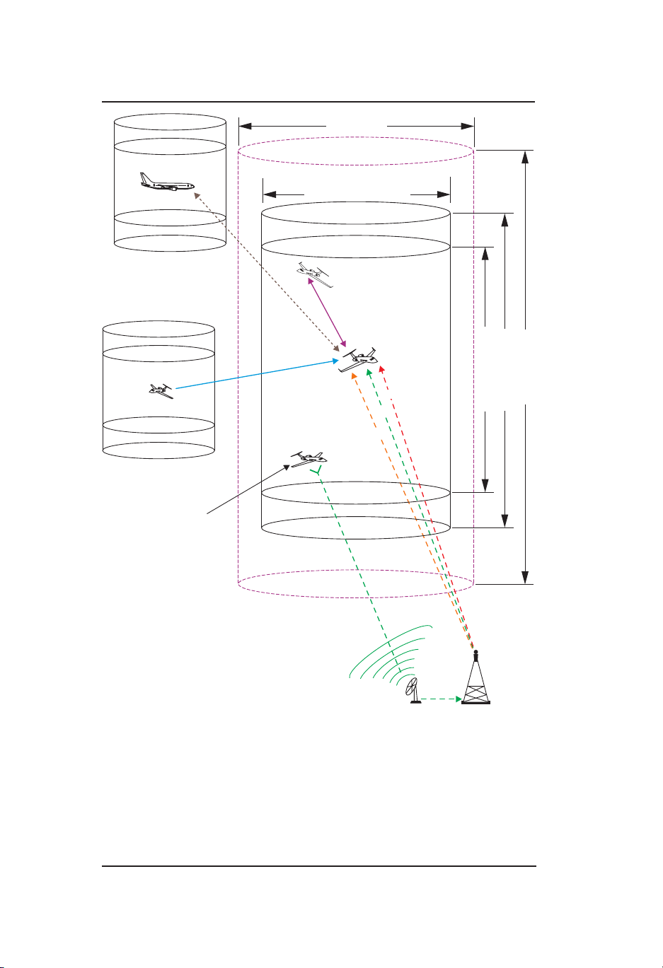
A composite of UAT / 1090ES trafc (UAT, 1090ES, ADS-R, TIS-B,
and TAS) is provided in Figure 1-3.
Lynx ® NGT-9000
Traffic Display
The Lynx NGT-9000 monitors the airspace around the aircraft using
ADS-B In (and TAS if equipped) to show other aircraft on the screen.
When within range of a participating ground station TIS-B and ADS-R
trafc services are also shown on the screen. Trafc is identied on
the screen using corresponding trafc symbols.
Traffic Advisory System (TAS)
The Trafc Advisory System (TAS) is an optional feature of the Lynx
NGT-9000. This feature provides the capability to interrogate nearby
aircraft transponders and issue Trafc Advisory (TA) alert as well as
a voice audio output that announces Trafc Advisories and relative
altitude to the ight crew. This option requires the installation of a
directional antenna.
ADS-B Traffic Advisory System (ATAS)
Release 2.0 or greater. The ATAS [also referred to as TSAA] option
provides trafc alerts using ADS-B In (ADS-B, ADS-R, and TIS-B)
trafc information. The TA alerts the ight crew aurally and visually in a
manner similar to a conventional Trafc Advisory System (TAS) which
assists the pilot in the visual acquisition of aircraft that may represent
a danger. Trafc Alerts are graphically depicted on the Lynx NGT-9000
panel mount units or on compatible external displays. ATAS and TAS
may operate at the same time with trafc information being correlated
by the unit. Refer to page 2-30 for details on operation.
Pilot’s Guide1-4
Page 19

Lynx ® NGT-9000
Description
Weather Display
The weather displays are optional features setup during installation
and when active are shown on the right application screen. Weather
information is obtained from the FIS−B system which is a ground
broadcast service provided through the ADS−B Services network
over the 978 MHz UAT data link. Three screens are available and are
designated as follows:
• Graphical Weather
• Winds and Temps Aloft
• Textual Weather Reports
Traffic and Weather Output Interfaces
The Lynx NGT-9000 can output trafc information via ARINC 429 and
RS-422. Weather information is output via RS-422. Weather and
trafc can be output on RS-232 via WiFI to be viewed on a personal
electronic device.
Built-In Test and Operational Status
The Lynx NGT-9000 uses fault monitoring on all stages of operation
from start up to power down and provides screen messages for
degraded or failed operation. In addition a system test is available
providing operational status of external data inputs.
Terrain Awareness and Warning System (TAWS)
Release 2.0 or greater. The Terrain Awareness and Warning System
(TAWS) is an optional function that continuously monitors the aircraft’s
position, altitude, speed, track, and phase of ight and compares the
information to an internal terrain, obstacle, and runway database.
If TAWS predicts a potential Controlled Flight Into Terrain (CFIT)
situation, the system alerts the pilot visually on the Lynx NGT-9000
display, aurally over the cockpit speakers or headset, or via cockpit
lamps (caution & warning).
Lightning Detection
Release 2.1 or greater. Lightning Detection is an optional function
provided by the interface of a WX-500 Stormscope. This information
is shown on the right application screen of the NGT-9000 Panel Mount
unit. This function is not available for the NGT-9000R Remote Mount
version.
Pilot’s Guide 1-5
Page 20
Description
+/- 10000 (TAS)
ATC-Ground Station
Other Aircraft 1090ES
70 nm ()TAS
30 nm (/ )TIS-B ADS-R
Other Aircraft
TAS
Own Aircraft
UAT / 1090ES
TAS (model option)
Lynx ® NGT-9000
Other Aircraft UAT
Other Aircraft
UAT Non-Equipped
Mode A/C Equipped
ADS-R
TIS-B
FIS-B
TIS-B
+/- 5000 (ADS-R)
+/- 3500 ft (TIS-B)
Figure 1-3: Example of Own Aircraft UAT, 1090ES, and TAS Traffic
Pilot’s Guide1-6
Page 21

Lynx ® NGT-9000
Description
EQUIPMENT DESCRIPTION
The Lynx NGT-9000 MSS family consists of the following standard and
optional equipment. Refer to the Aircraft Flight Manual Supplement to
determine what optional equipment is installed. Chapter 5 provides a
list of optional cockpit switches and lamps.
Required Equipment
• GPS Antenna
• L-Band (978MHz/1030/MHz/1090MHz) Antenna
• Detachable Conguration Module (DCM)
Optional Equipment
• Directional Antenna (required for TAS operation, and models with
TAS and diversity operation)
• Additional L-Band Antenna (required for diversity operation, and
no TAS operation)
• Trafc Display
• Weather Display
• WiFi Serial Adapter and Personal Electronic Device (PED)
• CP-2500 Control Panel (required for the remote mount version)
• WX-500 Stormscope (panel mount version only)
GPS Antenna and Internal GPS Receiver
The GPS utilizes signals from Global Positioning System (GPS)
satellite constellation and Satellite-Based Augmentation Systems
(SBAS). The Lynx NGT-9000 has an internal GPS function that provides position, velocity, time and integrity (NIC, NAC etc) information
to the applications. The antenna is located on the top of the aircraft.
L-Band Antenna
The L-Band antenna is used by the Lynx NGT-9000 to receive
1030MHz, receive and transmit 1090MHz and receive 978MHz. It is
located on the bottom of the aircraft.
A second L-Band antenna is installed on the top of the aircraft for
models with Diversity. Installations with both TAS and Diversity
options can use the TAS directional antenna instead of the second
L-Band antenna.
Pilot’s Guide 1-7
Page 22

Description
Lynx ® NGT-9000
Detachable Configuration Module (DCM)
The DCM is a solid-state device that retains software and hardware
conguration information. It is permanently attached to the aircraft via
the wiring harness and communicates with Lynx NGT-9000 via serial
bus. Conguration options are set up during installations and saved
in the DCM.
Directional Antenna
A directional antenna is used to receive 1090MHz and transmit
1030MHz for models with TAS.
Alternate Displays
Screen information may look different on displays interfaced with the
Lynx NGT-9000. Refer to that display’s manual for a description of
how information is depicted.
The operation and display features provided in this Pilot’s Guide are
specic to the information depicted on the Lynx NGT-9000.
Personal Electronic Device (PED)
The Lynx NGT-9000 supports the use of personal electronic devices
(e.g., tablets) via a WiFi connection. The PED must use compatible
applications that support the ADS-B broadcast services (i.e., ADS-B
In, TIS-B, ADS-R, and FIS-B). Check with an avionics dealer
or contact L-3 Avionics Systems for a current list of compatible
applications.
WiFi Serial Adapter
The Lynx NGT-9000 can be connect to a PED via WiFi using a
compatible WiFi Serial Adapter.
CP-2500 Control Panel
The CP-2500 is a control panel offered by L-3 Avionics Systems for
operation of the remote mount Lynx NGT-9000R. The operational
information provided in this guide is limited. Refer to the CP-2500
Pilot’s Guide (0040-17250-01) for detailed information.
WX-500 Stormscope
The WX-500 is a weather mapping system that detects electrical
discharges from thunderstorms within a 200 nmi radius of the aircraft.
This information plots the location of the thunderstorms and is shown
on the right application screen of the Panel Mount Lynx NGT-9000.
Pilot’s Guide1-8
Page 23

Lynx ® NGT-9000
CHAPTER 2
OPERATION - PANEL MOUNT
INTRODUCTION
This chapter describes the operation of the Panel Mount version of the
Lynx NGT-9000. Details on the optional cockpit switches and indicator
lamps are provided in chapter 3.
PILOT ADVISORY
The display of ADS-B data only supplements and does not replace
any operational procedure. All pilots/operators are reminded that the
airborne equipment that displays trafc is only for pilot situational
awareness. This equipment is not approved as a collision avoidance
tool and does NOT relieve the pilot of responsibility to “see-and-avoid”
other aircraft. Any deviation from an air trafc control clearance based
on cockpit information must be approved by the controlling ATC facility
prior to commencing the maneuver. Uncoordinated deviations may
place an aircraft in close proximity to other aircraft under ATC control
not seen on the airborne equipment and may possibly result in the
issuance of a pilot deviation.
• Occasionally the trafc display may show a “shadow” or duplicate
of your own aircraft on the trafc display. Generally this is caused
by a TIS-B track of the aircraft reported from a ground station. In
most cases, the own aircraft TIS-B tracks are detected and ltered
out by the NGT software. In some cases, own aircraft maneuvers
can cause enough separation of the TIS-B track from own aircraft
that it is treated as a new intruder and displayed. This is not an
error or malfunction in the system. As ground stations improve, the
occurrence of these shadows should be minimized or eliminated.
• Ground stations only produce TIS-B intruders for Mode C/S
equipped aircraft that have no ADS-B output. Mode A or nontransponder equipped aircraft are not reported as TIS-B intruders.
It is the pilots responsibility to “see and avoid”.
• Information shown on the display is provided to the pilot as an aid
to visually acquiring trafc. When under ATC control pilots should
maneuver their aircraft based only on ATC guidance or positive
visual acquisition of the conicting trafc. Maneuver should be
consistent with ATC instructions. ATC should be contacted for
resolution of the trafc conict.
Pilot’s Guide 2-1
Page 24

Operation - Panel Mount
• The transponder signal must be transmitting during all ight and
ground operations. It may be placed in standby only if the system
is inoperable or if advised by ATC to disable ADS-B.
• Loss of input data may not cause the NGT-9000 to fail but could
degrade operation. Failure and degraded conditions will be
annunciated by the NGT-9000 to alert the pilot to the operational
status. In many cases, fault conditions will recover if erroneous
data inputs are restored.
• Aircraft will be displayed when the information received meets
ADS-B, ADS-R, and TIS-B data integrity requirements.
Lynx ® NGT-9000
POWER ON
1. Depending on the aircraft use either the battery switches or
avionics master switch to apply power.
2. After power is applied the unit begins initialization and self-tests
begin.
3. When on ground the unit cycles through the following screen
sequence:
• Splash
• System Status / Version
• Flight ID (optional)
• Normal Operation
4. When in air and power is cycled the unit transitions to normal
operation within 5 seconds, bypassing the splash, version, and
ight ID screens.
Splash Screen
The splash screen is displayed in less than 5 seconds after power is
applied. The company name/Logo is shown on the left side and the
product name on the right. See Figure 2-1.
Figure 2-1: Example of Splash Screen
Pilot’s Guide2-2
Page 25

Lynx ® NGT-9000
Operation - Panel Mount
System Status / Versions Screen
The system status is shown on the left screen and should show
“System Pass” in green text along with an audio indication of “System
Test Passed”. The version screen is located on the right side and
shows the software and database version information. See Figure 2-2.
System Status
Power On Result:
System Pass
Flight Sw: 0000-00000-XXYZ
GPS/UAT RX: _ _ _ _ _ _ _
Airport DB: YYYYMMDD
Map DB: YYYYMMDD
TAWS DB: YYYYMMDD
Versions
Figure 2-2: Example of System Status / Version Screens
• If System Status is “System Fail”, then the message “Self-Test
Failures Occurred” is shown on the right side of the display and the
“System Test Failed” is heard through the aircraft audio system.
The option to restart the unit or to continue start up in a degraded
mode is shown on the right side of the display
• Tap the Restart button to restart the system.
• If the “System Fail” message continues to be seen tap the
Continue button to proceed. Refer to Chap. 5 (Troubleshooting)
for corrective actions.
• If System Status is “System Degraded”, then the message “See
MSG Window” is shown on the right side of the display.
• Tap Continue button to proceed. Refer to Chap. 5
(Troubleshooting) for corrective actions.
Pilot’s Guide 2-3
Page 26
Operation - Panel Mount
Lynx ® NGT-9000
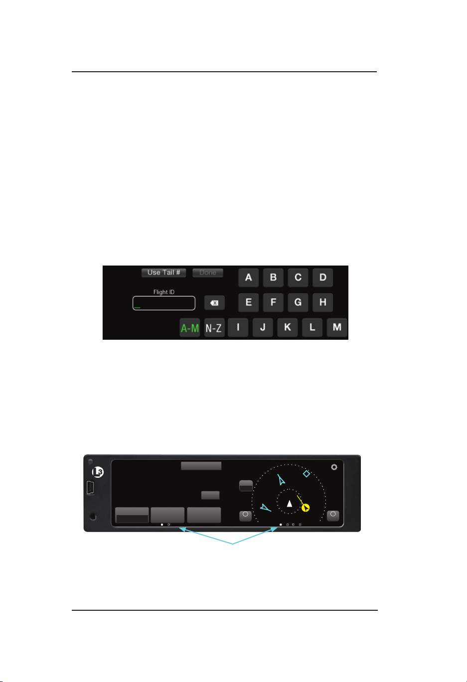
Flight ID Screen (optional)
The Flight ID Screen is a conguration option that must be setup during
installation. Most general aviation aircraft will be operated in a manner
that does not require Flight ID. See Figure 2-3. It is shown after the
System Status/Version Screen and shows the following information:
• The Tail # (call sign) button, located in the upper left, may be tapped
to be activated in place of a Flight ID.
• The Flight ID Number is entered using the keypad. The keypad will
change to numbers after three alpha characters are entered. When
complete, tap the Done button to proceed to normal operation.
• The last Flight ID entered is shown after power is cycled.
Figure 2-3: Example of Flight ID Screen
Normal Operation
Figure 2-4 shows an example of the unit in normal operation. When the
aircraft is on ground the System Test button and ON-GND indication
are shown. Functional instructions are located in the Basic Operation
section below.
System Test
1200
120
PA LT
N333TL
ID
Mode
ALT
00ft
Squawk
VFR
ON-GND
MSG
IDENT
Application Indicators
Figure 2-4: Example of Normal Operation
ALT
NRM
-
OUT
6
-01
-08
00
00
+
IN
Pilot’s Guide2-4
Page 27
Lynx ® NGT-9000
ALT
ALT
Operation - Panel Mount
BASIC OPERATION
The touch screen display is divided into left and right screens that
show information specic to the selected application. The user can
select, input, and adjust information on the screen using buttons,
edit boxes and screen objects using gestures (actions) such as tap,
momentary press, drag, or swipe.
Screen Buttons
The buttons are used to select, input, and adjust screen information.
The buttons have the following common functionality:
• Buttons are typically gray background color with white or green
text.
• The shape of a button can vary according it’s location.
• The button background highlights in blue when pressed.
• A button function that is inhibited has its button label grayed out.
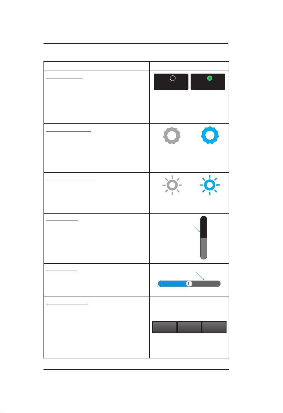
Table 2-1 provides examples of screen buttons, edit boxes, and other
screen objects and their functionality.
Table 2-1: Button Functions
NAME - FUNCTION EXAMPLE
Momentary Button: Use a tap action
Mode
Done
Status
Mode
on the momentary button to perform a
onetime function
Latch Button: Use a tap action on the
latch button to set a single function to
On or Off. Once pressed the button
retains the latched appearance
indicating that it is active.
Toggle Button: The toggle button is
used to control related functions of
which only one may be active at a
time. Performs a onetime action when
pressed that changes the selected
indicator located at the bottom of the
button. The background is blue only
while pressed.
Pilot’s Guide 2-5
Settings
Not Selected - Selected
Not Selected - Selected
Page 28
Operation - Panel Mount
Position Indicator
Slide Bar
Table 2-1: Button Functions (continued)
NAME - FUNCTION EXAMPLE
Radio Button: The radio button is used
to control related functions of which
only one may be active. The circular
button indicator is bright green when
the button function is active and is
dark when not active.
Options Button: The gear shaped
options button is used to access
options available for the application
screen. Tap the button to open the list
of options. The gear is blue only while
pressed.
Brightness Button: Used to increase
or decrease the display brightness
level. Tap the button to open a slide
bar. The button is blue only while
pressed.
Lynx ® NGT-9000
Above Above
Not Selected - Selected
Not Selected - Selected
Not Selected - Selected
Scroll Bar: The scroll bar is used to
navigate vertically through a list or
block of text. Use a drag or swipe
action to move the scroll bar.
Slider Bar: A slider bar is used to
increase or reduce a value. Use a drag
or swipe action to move the slider bar.
Options Tab: The Options Tab is
comprised of at least two latch buttons
and a “Done” momentary button. It is
used on the application option screens
to select between two “pages” of
information by tapping on the desired
page name on the tab.
Settings
Scroll Bar
Position Indicator
Status
Pilot’s Guide2-6
Done
Page 29
Lynx ® NGT-9000
Message Text
Function Activ
Table 2-1: Button Functions (continued)
NAME - FUNCTION EXAMPLE
Selection List: Selection Lists are
used where there is a list of items
from which a selection can be made.
A green lled circle is shown when
an item is selected. A drag or swipe
action is used to scroll the list up or
down.
Message Window: The message
window is used when a system
message is present that requires a
user response. Two function active
buttons can be arranged in a row
below the message text.
On/Off Button: This button is used to
indicate whether a function is enabled
(green) or disabled (dark).
Application Screens
Operation - Panel Mount
Self-Test Failures
Self-Test Failures
Buttons
ate
Restart
Occured!
Occured!
Continue
The display is divided into left and right screens with each screen
having access to a particular application. An Application indicator is
located at the bottom of each screen. The indicator shows the number
of available applications for that side of the display as well as the
current application setting. Each application can slide into view using
both Drag and Swipe actions. See Figure 2-4.
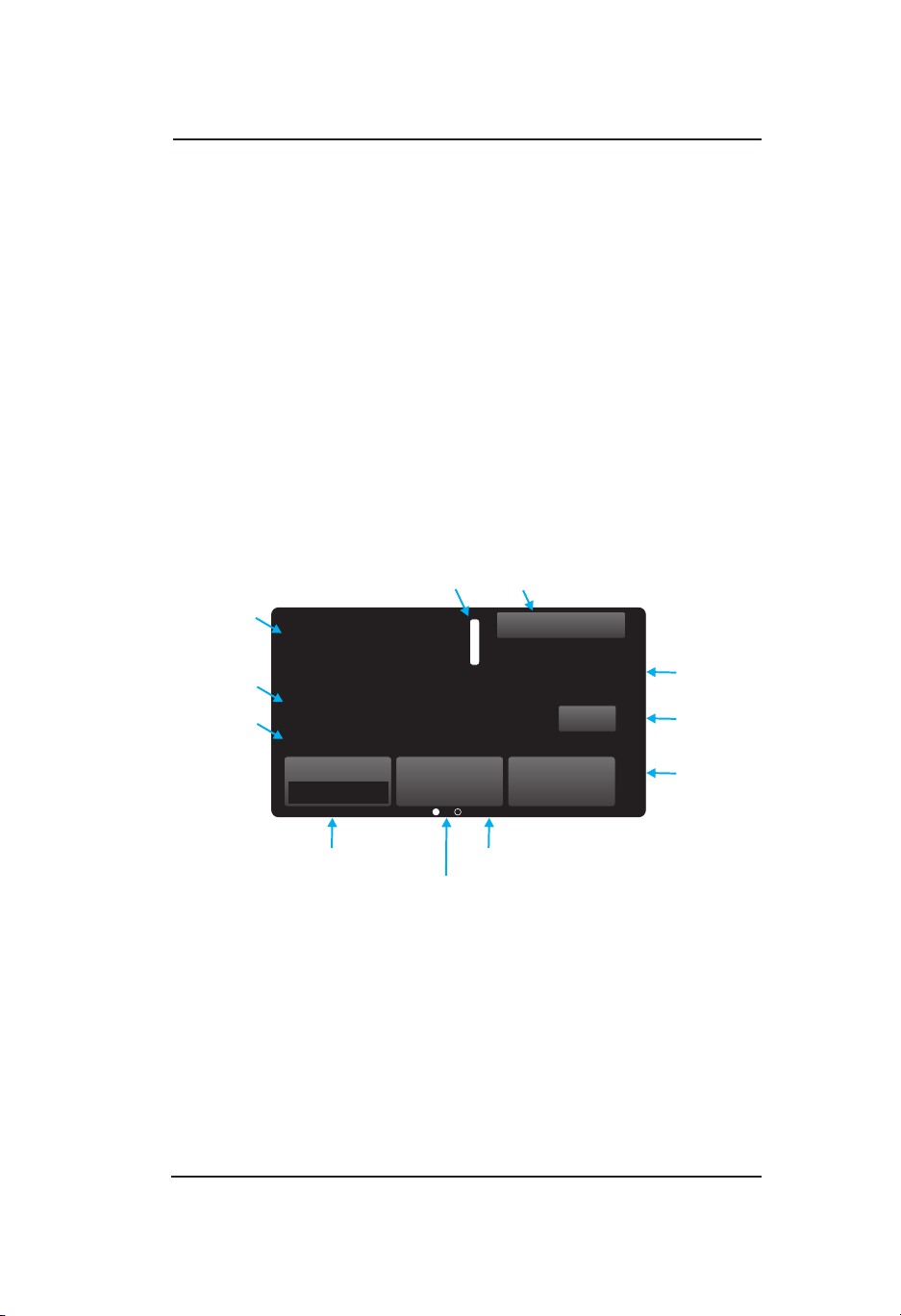
Left Screen
The left screen has two application indicators. The rst indicator (from
left to right) corresponds to the Transponder the second indicator
corresponds to Alternate Trafc.
The Transponder screen Displays Mode A Squawk Code, Pressure
Altitude, Flight ID or Call Sign (tail number).
The Alternate Trafc screen displays a Birds-eye display of trafc and
own-ship compliant with the requirements of AC 20-172B and DO317B for the purpose of supporting the Enhanced Visual Acquisition
(EVAcq) and Basic Airborne (AIRB) CDTI applications.
Pilot’s Guide 2-7
Page 30

Operation - Panel Mount
Lynx ® NGT-9000
Right Screen
The right screen has between two and six application indicators. The
number of indicators is dependent on the feature enablement.
The two screens that are always available are the Trafc and the
FIS-B Graphical Data Screen.
The Trafc Birds-eye display of trafc and ownship for the purpose
of supporting the Enhanced Visual Acquisition (EVAcq) and Basic
Airborne (AIRB) CDTI applications. This includes display of trafc
advisories, when installed and enabled (TAS or ATAS Optional).
The FIS-B Weather Graphic screen is a simplied moving map display
with depiction of ownship and the ability to selectively overlay graphical
FIS-B products such as METAR, TAF, NOTAMs, AIRMET, SIGMETs,
TFR and NEXRAD.
The following four screens are dependent on the feature enablement:
TAWS, Lightning, FIS-B Graphical Winds and Temps Aloft, and FIS-B
Textural Data.
The Terrain Awareness and Warning System screen displays a birds-
eye display of terrain, obstacles, airports, and ownship for the purpose
of supporting a Class B TAWS.
The Lightning screen displays electrical discharges from thunderstorms
within a 200 nmi radius of the aircraft. This Lightning data depicted as
cells or strikes. A “Nearby Strike Indicator (lightning bolt)” is shown
over the lightning application Dot when storm activity is detected.
The FIS-B Weather Graphic Winds & Temp Aloft screen is a simplied
moving map display with depiction of ownship and the ability to
selectively overlay winds and temps aloft at the desired ight level.
The FIS-B Weather Textual Data screen displays airport associated
textual products provided by FIS-B including METAR, TAF, NOTAMs.
The application indicators and their screens have the following order
(from left to right) when enabled: Trafc, TAWS, Lightning, FIS-B
Graphic Data, FIS-B Graphical Winds & Temps Aloft, and FIS-B
Textual Data.
Pilot’s Guide2-8
Page 31
Lynx ® NGT-9000
Indication
Mode
Squa
Call Sign
Transponder Active
Function Button
Operation - Panel Mount
TRANSPONDER OPERATION
The transponder receives interrogations from surrounding aircraft and
from ATC and then transmits replies.
Ground stations can interrogate Mode S Transponders individually
using a 24-bit ICAO Mode S address, which is unique to the particular
aircraft. In addition, ground stations may interrogate the unit for its
transponder data capability and the aircraft’s Flight ID.
The transponder application is the rst screen on the left side of the
display as indicated by the application indicator. See Figure 2-5 and
the functional description below for operating instructions.
Release 2.1 or greater. An external Standby Mode switch is available.
See Chapter 4 for details on Transponder screen and operation
changes.
A
wk
Code
Pressure
Altitude
Flight ID
or
Squawk Code
When the Squawk Code text is tapped, the Squawk Code Edit Screen
is shown. See Figure 2-6. The current Squawk Code continues to be
transmitted until the last digit of the new Squawk Code is entered. The
edit mode is canceled by tapping the Squawk Code before the fourth
digit is entered, or after 5 seconds of inactivity, or if a Trafc Advisory
or TAWS Alert occurs.
Pilot’s Guide 2-9
IDENT or Reply Message
1200
120
PA LT
N333TL
ID
Mode
ALT
XPDR Mode
Control
Figure 2-5 Transponder Application Screen
00ft
Squawk
VFR
Application Indicator
(On Ground Only)
I
System Test
D
E
N
T
ON-GND
MSG
IDENT
Squawk Button
ON-GND
Message
Button
IDENT
Button
Page 32

Operation - Panel Mount
Lynx ® NGT-9000
Current Pressure Altitude
The current pressure altitude (PALT) is located below the Squawk
Code. A value greater than 99,900 ft will set the value to 99900 with
amber text. An invalid pressure altitude is shown as amber dashes.
Flight ID / Call Sign
The Flight ID or Call Sign (tail number) is located below the PALT.
During initial installation either the tail number is setup to be shown
or the Flight ID can be set each ight using the Flight ID screen
(conguration option).
Mode Control
The Mode Control toggle button has the following selections: Standby
(SBY), On (ON), and Altitude (ALT).
• ALT is the default mode. It puts the transponder in ATC
mode C. When the aircraft is In-Air the transponder replies to
interrogations and includes the plane’s pressure altitude in the
replies.
The transponder should be in this setting when In-Air or OnGround unless otherwise directed by ATC.
When On-Ground, the display includes an “ON-GND” indication.
While On-Ground the transponder does not reply to Mode C/S AllCall interrogations and outputs ADS-B at a slower surface rate.
• Selecting Standby stops all transponder transmission.
• Selecting ON puts the transponder in ATC mode A in which it
replies to interrogations, but does not report the plane’s altitude.
A “FAIL” message, in amber text, is shown if a transponder failure is
detected.
Transponder Reply
When the transponder (XPDR) reply is active an “R” indicator is shown
to the right of the Squawk Code. The “R” is replaced with “IDENT”
when the IDENT button is tapped.
IDENT Button
Tap the IDENT button to transmit the Special Identication (SPI) pulse.
An IDENT pulse highlights the aircraft’s symbol on the ATC’s radar
screen and is identied on the screen next to the squawk code.
Pilot’s Guide2-10
Page 33

Lynx ® NGT-9000
Operation - Panel Mount
Squawk VFR Button
Tap the Squawk VFR toggle button to change the transponder squawk
code to a predened (1200) VFR value. The value shown on the button
is the code that is activated when the button is tapped. A second press
reverts the transponder to the previous squawk code.
Release 2.1 or greater. The Squawk button can be removed from the
transponder screen. Do this by entering the edit screen and tapping
the Enabled button. The buttons green light turns gray and is shown
as “Disabled”.
Cancel
VFR Code
1200
ENABLED
Figure 2-6: Squawk Code Edit Screen
Done
0
X
2
4
6
1
3
5
7
MSG Button
If a new message is available a ashing MSG button is shown on the
left screen. Tap the MSG button to view fail or degraded messages
during normal operation.
Once the messages in the message window have been viewed, the
MSG button will stop ashing. When all messages have cleared, the
MSG button is removed from the screen. On the Message window tap
the Done button to return to the previously viewed screen.
Refer to the Chap. 5 (Troubleshooting) for corrective actions.
ON-GND Indicator
The ON-GND indicator provides the pilot a notication that the
transponder is operating in the on-ground mode (does not reply to
all-calls).
System Test Button
The System Test button is available only when the aircraft is on the
ground. Tapping the button initiates the Test. During the System Test
the user functions are disabled and the right screen shows a preset
trafc display with the message “Self Test In Progress” at the top of the
screen. See Figure 2-7.
Pilot’s Guide 2-11
Page 34

Operation - Panel Mount
System Status
Self Test In Progress
Lynx ® NGT-9000
ADS-B In:
ADS-B Out:
Transponder:
FIS-B:
TAS:
ATAS:
TAWS:
Pass
Pass
Pass
Fail
Pass
Pass
Degraded
6
+10
-10
-02
Figure 2-7: Example of System Test Screen
The left screen shows the system affect of the tests results on the
functional areas of the system.
Note – Release 1: Functions that are not part of the installation are not
shown. Release 2.0 or greater: TAS, ATAS, and TAWS are listed with
a “disabled” indication if not installed. FIS-B is removed from the list if
it is disabled.
Note - Individual test failures are recorded in the fault log. (Accessible
to service personnel only.)
The unit returns to normal operation if no failures are detected within
5 seconds.
• If a “Fail” or External Fail” is shown for any of the system functions,
then the message “Self-Test Failure” is shown on the right side of
the display as well as the option to restart the unit or to continue
operation in a degraded mode.
• Tap the “Restart” button to reset the unit and once it is operational,
perform the System Test again. If the failures continue tap the
“Continue” button to proceed in a degraded operational mode.
• If “Degraded” is shown for any of the system functions, then the
message “Service Unit Soon” is shown on the right side of the
display.
• Tap Continue screen button to proceed.
Correct failures before going any further with the functional check.
Note: It is normal to show degraded for certain functions if some
aircraft systems are still aligning, or if the GPS has not yet acquired
a signal.
• On the Transponder Screen, tap the “MSG” button located on the
Transponder Application screen to view fail messages.
• Check signal availability when failures for ADS-B In, FIS-B, GPS,
or TAS are noted.
• Refer to the Chap. 5 (Troubleshooting) for corrective actions.
Pilot’s Guide2-12
Page 35

Lynx ® NGT-9000
Operation - Panel Mount
TRAFFIC OPERATION
The Lynx Multi-Link Surveillance System monitors the airspace around
the aircraft using ADS-B In (and TAS if equipped) to communicate with
like equipped aircraft with ADS-B Out and shows these other aircraft
on the screen. When within range of a participating ground station
TIS-B and ADS-R trafc services are also shown on the screen. Trafc
is identied on the screen using corresponding trafc symbols. Refer
to the descriptions below and Figure 2-8 for detailed information.
Limitations
1. The ADS-B, ADS-R, TIS-B, and TAS trafc information assists
the pilot in visually acquiring trafc while airborne and is expected
to improve both safety and efciency by providing the pilot with
enhanced trafc awareness. This functionality does not relieve the
pilot of “see and avoid” responsibilities as described in 14 CFR
91.113b.
2. Trafc information shown on the Lynx NGT-9000 is dependent
on other aircraft having similar ADS-B equipment, or a Mode A/C
transponder for models with TAS, or being in range of a ground
station that provides TIS-B and ADS-R. If another aircraft cannot
meet these requirements, then the other aircraft will not be
displayed on the Lynx NGT-9000.
3. The EVAcq, AIRB, and ATAS functions are unavailable when
ownship position is beyond 85 degrees North or South latitude.
The result is a display of “Trafc Unavailable” on Panel mount units
and an indication of “Standby” for remote displays. However, for
NGT-9000 installations, where TAS is enabled, the range/bearing
based TAS targets are displayed.
Traffic Advisory
The TAS and ATAS functions are optional features providing advisories
via aural announcements over the cockpit speakers or headset and
visually via the display or a cockpit lamp. ATAS and TAS may operate
at the same time with trafc information being correlated by the Lynx
NGT-9000. Details on these features are shown on page “Trafc
Advisory Systems” on page 2-30.
Pilot’s Guide 2-13
Page 36

Operation - Panel Mount
Zoom In
Options
TIS-B No Coverage Indicator
TIS-B No Coverage Indicator
Lynx ® NGT-9000
Traffic Screen
The trafc screen has a black background. Transponder Mode can be
set to Standby (SBY), On (ON), or Altitude (ALT).
The Trafc application is available on both the left and right screen.
The Trafc information is shown if ADS-B or TAS data is valid.
A “Trafc Failed” is displayed if both ADS-B and TAS (optional) are
failed. “Trafc Unavailable” is displayed if ADS-B In has no heading
or track available and TAS (if installed) is in standby. See Figure 2-8
for an example of Trafc Screens. Refer to the Functional Description
below for detailed information.
If TAS or ATAS options are congured and the trafc screen is not
being displayed on either the left or right screen and a trafc advisory
occurs, the trafc screen automatically opens on the right screen if
there is no TAWS Alert (option) active and will open on the left screen
if a TAWS alert is active.
Transponder Mode
Transponder
Banner
Selected
Traffic GS
Selected
Traffic ID
Selected
Traffic Info Button
Range
Indication
Button
XPDR
i
ALT
NRM
-
Out
Altitude
Mode
1200
6
-01
-08
Directional Ownship
Circle indicates symbol is selected
00
00
Traffic Mode Indicator
On
N333TL
150 kts
MSG
TAS
STBY
+
In
Figure 2-8: Traffic Applications Screen
i
ALT
NRM
-
Out
Zoom Out
6
-08
-01
00
Acknowledge Button
Pilot’s Guide2-14
00
N333TL
150 kts
TAS
STBY
+
In
Page 37

Lynx ® NGT-9000
Operation - Panel Mount
Ownship Symbol
The ownship is shown as a white triangle on the trafc display. When
ownship direction source is not valid the ownship symbol is a white
circle with a black inset. Ownship orientation matches ownship
heading when available or track angle if heading is not available.
Traffic Symbols
The trafc symbols indicate the approximate range, relative bearing,
and relative altitude of intruder aircraft. Trafc data with directional
data for intruder aircraft are shown as arrowheads. Trafc data without
directional data for intruder aircraft are shown as diamonds.
• A solid amber circle (or with a black lled arrowhead) is a Trafc
Advisory (TA) that represents an intruder aircraft that may pose a
collision threat. (A semi-circle at the edge of the display represents
an off-scale TA).
• Units with the optional TAS feature (e.g., NGT-9000+ or NGT9000R+) display trafc advisory symbols and output aural TA
warnings (Release 1 “trafc, trafc” or Release 2.0 or greater
“Trafc” with the other aircraft clock position) that are annunciated
over the cockpit speaker or headset. Note - Optionally available
extended call-outs including the relative attitude and range (low,
5 miles). This is a congurable option selected at the time of
installation.
• Units with the optional ATAS feature (Release 2.0 or greater)
display trafc advisory symbols and output aural TA warnings
(“Trafc” along with the other aircraft clock position) that
are annunciated over the cockpit speaker or headset.
Note - Optionally available extended call-outs including the relative
attitude and range (low, 5 miles). This is a congurable option
selected at the time of installation.
• A solid diamond or arrowhead is a Proximity Advisory (PA) that
represents trafc that is close but does not pose an immediate
collision threat.
• A hollow diamond or arrowhead indicates Other Trafc (OT) that
represents trafc that does not pose an immediate threat.
• Directional intruders are oriented such that symbols point in the
direction of their reported heading or track, relative to own aircraft
direction.
Pilot’s Guide 2-15
Page 38

Operation - Panel Mount
• A velocity vector arrow may be appended to the right side of a
trafc symbol to indicate that the intruder aircraft is ascending (up
arrow) or descending (down arrow) faster than 500 fpm. No arrow
is shown for intruder aircraft in level ight, or for those moving
vertically slower than ±500 fpm, or for non-altitude-reporting
intruder aircraft.
• A two digit number may be appended to trafc symbols to indicate,
in hundreds of feet, the relative altitude of the intruder. For example
+03 means the intruder aircraft is 300 ft above ownship. A positive
data tag is displayed above the trafc symbol to emphasize that
the intruder aircraft is above your aircraft. A negative data tag is
displayed below the trafc symbol. If the intruder is at the same
altitude as the aircraft, “00” is displayed below the trafc symbol.
The data tag for a vertically out of range TA displays the relative
altitude of the intruder regardless of the current vertical display
mode. Only display data tags for altitude reporting aircraft are
shown. Non-altitude reporting aircraft are considered to be at the
same altitude as ownship.
• Tapping a trafc symbol generates a circle around it indicating that
the trafc symbol is selected. In addition the following is displayed:
Selected Trafc Info Button, Selected Trafc ID, and if enabled the
Selected Trafc Ground Speed (GS). Tap the trafc symbol again
to remove the circle and data.
• When TAS functionality is enabled and in installations with no
heading source, the TAS trafc (referenced to heading) and ADS-B
trafc (referenced to track) are displayed simultaneously. The
ADS-B targets will therefore appear skewed by the crab angle of
the aircraft.
• When TAS functionality is enabled and in installations with no
heading source, low speed operations (< 7 knots) will result in a
removal of the ADS-B tracks because ownship track can not be
adequately determined. TAS Only text will appear on the display if
TAS is enabled. This can happen in both rotorcraft hover operations
and when xed wing/rotorcraft aircraft are on-ground.
Lynx ® NGT-9000
See Table 2-2 for a list and description of trafc symbols used by the
panel mount unit.
Pilot’s Guide2-16
Page 39

Lynx ® NGT-9000
Table 2-2: Traffic Symbols
SYMBOL DESCRIPTION - EXAMPLE
Airborne Directional Trafc Advisory (TA)
(TAS or ATAS option only)
Airborne Directional Proximity Advisory (PA) *
Airborne Directional Other Trafc (OT) *
(Panel mount only)
Airborne Non-directional (TA)
(TAS or ATAS option only)
Airborne Non-directional (PA) *
Airborne Non-directional (OT) *
On Ground Directional (OT)
Operation - Panel Mount
Ground Vehicle Directional
On Ground Non-directional (OT)
Ground Vehicle Non-directional
Airborne Directional TA Trafc symbol with a data
tag indicating a relative altitude of 100ft below with a
horizontal velocity vector. (Panel mount only)
-01
Airborne Directional Other Trafc symbol with a data
tag indicating a relative altitude of 800ft below own
-08
* To promote cockpit commonality, installation conguration options
are available to set the airborne PA & OT trafc color to either cyan
or white.
Pilot’s Guide 2-17
aircraft descending with a horizontal velocity vector.
(Panel mount only)
Page 40

Operation - Panel Mount
Lynx ® NGT-9000
Trafc Display Priority
When multiple intruders are displayed, some overlapping of symbols
and/or data may occur. In these instances, the intruder with the
greatest threat partially or completely overlaps the intruders that pose
lower threats. Threat levels are calculated based on the intruders’
proximity, heading, altitude, and speed.
Trafc is displayed on the screen using the following priority scheme:
1. TAS Trafc Advisories
2. ATAS Trafc Caution Alerts
3. Selected Trafc
4. Proximate Advisories
5. Other Trafc
Traffic Altitude Mode
The available Trafc Altitude Modes are shown on a Toggle button
with green text. The altitude ranges are in relation to the ownship. A
description of each mode is detailed below:
• Normal (NRM): Trafc is displayed from altitudes of between
-2,700 and +2,700 ft. This mode is typically used during the
enroute phase of ight to reduce screen clutter.
• Above (ABV): Trafc is displayed from altitudes of between
+9,000 and -2,700 ft. This mode is typically used during takeoff.
• Below (BLW): Trafc is displayed from altitudes of between
+2,700 and -9,000 ft. This mode is typically used during approach
and landing.
• Unrestricted (UNR): Trafc is displayed from altitudes of between
+9,900 and -9,900 ft. This mode is typically used during the
enroute phase of ight to show all aircraft within the entire
detection area.
The Altitude Mode button is available only when the status of the
aircraft is In-Air. When the aircraft status is On-Ground the altitude
mode button is replaced with the TFC button.
See Figure 2-8 for a graphic representation of the Trafc Display
Modes and Trafc Zones.
Pilot’s Guide2-18
Page 41

Lynx ® NGT-9000
Operation - Panel Mount
Zoom Buttons
Zoom In (+) and Zoom Out (-) buttons are located on the bottom of
each trafc screens. The buttons are used to change the trafc display
range.
Range Rings
The range rings are oriented around the ownship. A range indicator is
located outside the upper left corner of the outer most ring. Bearing
indicators are shown on the 2 nm range ring. The range ring setting is
controlled by the zoom buttons.
The Trafc screen has the following display range with additional inner
rings as noted:
• Range 40 has 40 nm and 24 nm range rings.
• Range 24 has 24 nm and 12 nm range rings.
• Range 12 has 12 nm and 6 nm range rings.
• Range 6 has 6 nm and 2 nm range rings.
• Range 2 has only the 2 nm range ring.
• Range 1 has only the 1 nm range ring.
• Range 0.5 has only the 0.5 nm range ring.
TFC Button
The Trafc (TFC) button replaces the Trafc Altitude Mode button
when the status of the aircraft is On-Ground. The button also activates
TAS (optional) when the aircraft is On-Ground. A description of each
mode is detailed below:
• Ground (GND): The display shows ADS-B ground trafc only
and places TAS (if installed) in Standby. TAS Standby indication
is located on the Trafc Mode Indicator. This is the default mode
when the aircraft goes on ground.
• Air (AIR): The display shows air trafc only and activates TAS (if
installed).
• All (ALL): The display shows air and ground trafc and activates
TAS (if installed).
Note
When no heading source is available and when going
through low speed operations (< 7 knots), ADS-B tracks
are removed because ownship track can not be adequately
determined. If TAS is not active, a “Trafc Unavailable”
message is displayed.
Pilot’s Guide 2-19
Page 42

Operation - Panel Mount
Lynx ® NGT-9000
Transponder Banner
When the trafc application is displayed on the left screen, the
transponder banner is displayed at the top of the left screen with the
following information:
• Quick return button is labeled “XPDR” and is used to return to the
Transponder Application screen
• Mode A squawk code
• Reply “R” or Ident “ID” indicator shown to the right of the squawk
code when either function is active.
• Current transponder operating mode status indicator with green
text. An amber “XPDR Failed” is shown when the transponder
function has failed.
Traffic Mode Indicator
The Trafc Mode Indicator is available only when a Lynx NGT-9000
with TAS is installed. Otherwise the “ADS Only” is assumed to be
operating for non-TAS installs.
The indicator is located above the Zoom in (+) button. The possible
modes of operation are detailed below:
• TAS STBY: This mode is shown if the TAS is in standby.
• TAS Only: This mode is shown if the TAS is operating and ADS-B
trafc is not available.
• ADS Only: This mode is shown if TAS has failed (or not available)
and ADS is operating.
A “Trafc Failed” message is shown with amber text when all available
trafc functions have failed. This results in all the trafc symbols being
removed from the trafc screen.
A “Trafc Unavailable” is shown with white text when insufcient
information is available to display trafc. This results in all the trafc
symbols being removed from the trafc screen.
MSG Button
The MSG Button seen on the Trafc Screen has the same functionality
as the one shown on the Transponder screen. See page 2-11 for
details.
Traffic Options Button
The gear shaped Options Button is located in the upper right corner
of the right application screen. Tap the button to open the options
screen.
Pilot’s Guide2-20
Page 43
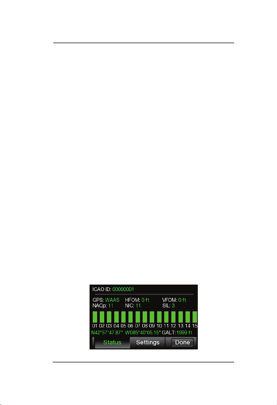
Lynx ® NGT-9000
Operation - Panel Mount
Trafc Options Screen
Two latch buttons and a done button are located on the bottom. The
Status button opens a screen showing GPS satellite information. The
Settings button opens a screen allowing the setting of Initial Trafc
Altitude Mode, VFR Squawk Code, Display Brightness Trim, and Flight
ID (if congured). Tap the Done button to close the Options Screen.
Options - Status
See Figure 2-9. The status screen provides the following GPS
information:
• 24 Bit ICAO ID (Mode S Identier): This value is displayed in octal
format.
• NACp (Navigation Accuracy Category for Position): This value is
determined using HFOM data.
• NIC (Navigation Integrity Category): this value is determined
using HPL data.
• Navigation Solution Mode (GPS), possible indications are:
• “No Pos” - unknown or DR [Insufcient Satellites to compute a
position]
• “2D” - 2D Nav, no integrity [Sufcient satellites to compute a
lateral position, but not to compute either HPLSBAS or HPLFD]
• “3D” - 3D Nav, no integrity [Sufcient satellites to compute a
lateral and vertical position, but not to compute either HPLSBAS
or HPLFD]
• “FDE” - RAIM/Alt (aided integrity) [HPLFD computed using
barometric altitude aiding is valid]
• “WAAS” - RAIM [HPLSBAAS is valid or HPLFD computed
without using barometric altitude aiding is valid]
Figure 2-9: Traffic Options Screen - Status
Pilot’s Guide 2-21
Page 44

Operation - Panel Mount
• “Error” - SVERROR (trying to exclude) [Fault detection detects
a position failure which cannot be excluded within the time-toalert when integrity is being provided by FDE]
• SIL: This value is always 3. Displayed GPS Satellite information is
shown as horizontal bars in increasing numerical order. The bars
are green-lled for greater signal strength and gray-lled when
no signal is detected. The bars should be at least 40-50% greenlled .
• Latitude and Longitude data: Shows the GPS computed own
aircraft latitude/longitude in degrees, minutes, seconds.
• Release 2.1 and earlier. GPS Altitude (GALT): Shows the GPS
computed own aircraft altitude (Height Above Ellipsoid (HAE) in
feet.
• Release 2.1 or greater. GPS Altitude (GSL): Shows the GPS
computed own aircraft altitude (Height Above Geoid). -Approximate
MSL- Not to be used for navigation)
• HFOM (Horizontal Figure of Merit): An indication of the quality of
the GPS position for horizontal position data.
• VFOM (Vertical Figure of Merit): An indication of the quality of the
GPS position for vertical position data.
If no valid data is available for the GPS data a white dash is inserted.
Lynx ® NGT-9000
Options - Settings
The Settings screen provides the following information and
functionality: See Figure 2-10.
• Radio buttons to set the trafc altitude mode (Normal, Above, and
Unrestricted). This selects the default altitude mode used when
the aircraft goes in-air. This is also used as the altitude mode
when on the ground and the “TFC” button has selected “AIR” or
“ALL”.
• Display Brightness Trim button is used to open a slide bar to adjust
the screen brightness up or down from the automatic brightness
control setting. This is trim adjustment not a 0 to 100% control.
• The VFR Code button is a means to update the default VFR
code to use when the “Squawk VFR” button is pressed on the
transponder application screen. Tap the button to go to a VFR
Code edit screen to set a new VFR code. NOTE: This should be
set to 1200 for use in the USA.
• A Flight ID toggle button is shown if congured. Tap the button to
open the Flight ID Edit screen.
Pilot’s Guide2-22
Page 45

Lynx ® NGT-9000
Operation - Panel Mount
VFR Code
1200
Initial Traffic Altitude Mode:
Normal
Above Unrestricted
Status Settings
Figure 2-10: Traffic Options Screen - Settings
FLTID
AAA 1234
BRT
Done
Acknowledge Button
The Acknowledge Button is located on the right side of trafc screen
and appears as a speaker icon. The acknowledge button is available
when the optional TAS or ATAS function (Release 2.0 or greater) is
congured and after a traffic advisory is detected. The Acknowledge
button is used to cancel the audio from a Trafc Aural. The TA will still
be active on the display.
Selected Traffic Info Button (i)
The selected trafc info button appears on the left side of both the left
and right screen after a trafc symbol is pressed. When the button is
tapped a trafc information window is located over the top of the trafc
screen.
TIS-B No Coverage Indicator
When congured to be enabled (required in the U.S.), the indicator
is located next to the Zoom Out button and is shown when TIS-B /
ADS-R data is not available in the area (i.e. out of range of a ADS-B
ground station).
• The indicator is also shown if a problem exists with the NGT-9000
System. See the troubleshooting section.
• The indicator will not be shown when TAS (if installed) is operational
(i.e. installed, not failed, not in standby).
Pilot’s Guide 2-23
Page 46

Operation - Panel Mount
Lynx ® NGT-9000
Traffic Information Window
The window is shown over the trafc screen and provides the following
data and functionality:
• Flight ID of the selected aircraft.
• Emitter Category or “type” of aircraft.
• An aircraft Icon is located on the right side of the window showing
a representation of the aircraft being tracked. If there is no aircraft
icon available then:
• Release 2.0 or earlier: A “?” is shown.
• Release 2.1 or greater: A text indication of the source of the
trafc is shown (TIS-B, TAS, ADS-R, or ADS-B).
• Calculated ground speed of the selected aircraft.
• A Display GS Latch button is used to activate the selected Trafc
GS on the trafc screen.
• Tap the Done button to close the window. The window is also
removed from the screen if a Trafc Advisory or TAWS Alert is
detected.
• See Figure 2-11 for an example of the Trafc Information Window.
Information
FLT ID: N123CD
Type: Small
GS: 105kts
Display GS
Figure 2-11: Example of Traffic Information Window
Done
Selected Traffic ID
The Selected Trafc ID is located along the right side of the trafc
screens after a trafc symbol is pressed. The Trafc ID is removed
when the selected trafc symbol is tapped, a Trafc Advisory (TA)
occurs, or if the selected trafc is no longer being tracked. The Trafc
ID is restored to the screen if the Trafc Advisory is no longer present
and if no other user action (i.e., selecting a different trafc symbol,
tapping a button, or changing the zoom range) has occurred since the
Trafc Advisory occurred. See Figure 2-8.
Pilot’s Guide2-24
Page 47

Lynx ® NGT-9000
Operation - Panel Mount
Selected Traffic GS
The Selected Trafc GS (if congured) is located along the right side
of both screens (under the selected trafc ID) after a trafc symbol is
pressed. The Trafc GS is removed when the selected trafc symbol
is tapped, a Trafc Advisory (TA) occurs, or if the selected trafc is no
longer being tracked. The Trafc GS is restored to the screen if the
Trafc Advisory is no longer present and if no other user action (i.e.,
selecting a different trafc symbol, tapping a button, or changing the
zoom range) has occurred since the Trafc Advisory occurred. See
Figure 2-8.
True Track (TRK)
This indication is located on the lower right side of the trafc screen
when a heading source is congured as an input, but the heading
source is not operational.
AURAL ANNOUNCEMENTS
Aural Trafc Advisories are provided by the optional TAS function or
ATAS function (Release 2.0 or greater).
“Trafc, Trafc” (or “Trafc”& aircraft clock position Release 2.0 or
greater) is a normal aural component of a trafc advisory is announced
once over the cockpit speakers or headset when a TA is rst detected.
This aural announcement will not be heard if audio is inhibited. It may
also be delayed if a higher priority alert is occurring at the time of the
alert.
Do not rely solely on the aural alerts for intruder aircraft
information. Use the display to view the latest TA and aircraft
information.
Units with the TAS feature Aural announcements are only made when
the TA rst occurs and may be inhibited.
Units with the ATAS feature have 2 alert level or “zones”. The Protected
Airspace Zone (PAZ) and the Collision Airspace Zone (CAZ). Alerts
may be generated for both of these alert zones so one TA aircraft may
generate 2 alerts for ATAS.
Pilot’s Guide 2-25
Page 48

Operation - Panel Mount
Lynx ® NGT-9000
Extended Audio Callouts
The Extended Audio Callouts is a conguration option that adds
relative bearing, relative altitude (when available) and range to the
intruder information announced as well as the normal alert (or relative
altitude, range, and vertical sense for Release 2.0 or greater) It is
available to both the TAS and ATAS functions.
• The relative bearing provides a clock bearing (e.g. “12 O’clock).
• The relative altitude (if available) announces either “High” if > 50 ft
or “Low” if < -50 ft or “Same Altitude” if > -50 ft and < 50 ft of own
altitude).
• The range in nautical miles (slant range if TA is not Non Attitude
Reporting (NAR) or Flat range if TA is NAR).
Release 2.0 or greater:
• The Vertical Sense (if available) announces either:
• “Climbing” if vertical rate is >= 500 fpm
• “Descending” if vertical rate is <= -500 fpm
• “Level” if vertical rate is > -500 fpm AND < 500 fpm
Some examples of extended audio alerts are:
• Release 1 “Trafc, Trafc, 10 O’clock high, 5 miles” This
aural announcement is for an intruder at a relative bearing of 300
degrees, at a higher altitude, 5 miles away.
• Release 2.0 or greater “Trafc, 6 O’clock same altitude, less
than a mile, level” This aural announcement is for an intruder at
a relative bearing of 180 degrees, at the same altitude, less than a
mile away, ying level.
AUDIO INHIBIT
Audio may be inhibited (canceled or suppressed) in the following
ways:
• The optional Audio Mute feature is used by an external CAWS
Alerting System to mute the Trafc Advisory system due to a
higher priority audio annunciation (i.e., stall warning > Terrain Alert
> Trafc Avoidance.)
• (Release 2.0 or greater) Press the external mounted Audio
Acknowledge Button (located on the yoke or panel) to cancel the
current aural announcement.
Pilot’s Guide2-26
Page 49

Lynx ® NGT-9000
• (Release 2.0 or greater) Tap the Acknowledge Button on the Lynx
NGT-9000 trafc display to cancel the current aural announcement.
• (Release 2.1 or greater) Conguration Options “TAS Ground
Filtering”: (1-standard) Aural trafc alerts from TAS functions are
suppressed when ownship is below 380ft AGL (above ground
level). (2-alternate) Aural Trafc Alerts suppressed when ownship
is below 5ft AGL.
• No trafc alerts are generated for aircraft that are on-ground even
though ground-based symbols are displayed by ADS-B.
Operation - Panel Mount
DETAILS ON TRAFFIC OPERATION
Operational details for ADS-B, ATAS, ADS-R, and TIS-B are provided
below. This information is being provided to help in the understanding
of the Lynx NGT-9000 ADS-B trafc system .
Automatic Dependent Surveillance - Broadcast (ADS-B)
ADS-B improves situational awareness and ight safety by providing
real time trafc information. The ADS-B In function is used to
receive ground station supported TIS-B and ADS-R trafc, and
direct communication with nearby like equipped aircraft (with Mode
S or UAT). The ADS-B Out (1090ES) function is used to periodically
broadcast (without interrogation) information about the aircraft that
includes aircraft identication, position, altitude, velocity and other
aircraft status information.
• ADS-B does NOT relieve the pilot of responsibility to “see-andavoid” other aircraft.
• No avoidance maneuvers are provided for, nor authorized, as a
direct result of a ADS-B other aircraft being displayed in the cockpit.
Avoidance maneuvers must be based on visually acquiring the
target
• The trafc display shows the relative position of ADS-B or standard
trafc using text, shapes, and colors. ADS-B also provides similar
information on ADS-B equipped ground vehicles.
• The effective surveillance range is 60 nmi (ADS-B In) The passivemode surveillance range is 160 nmi and maintains report messages
for a minimum of 200 1090ES ADS-B participants and 300 UAT
ADS-B participants simultaneously. To reduce display clutter a set
number of other aircraft of the highest priority other aircraft are
displayed at a time.
Pilot’s Guide 2-27
Page 50

Operation - Panel Mount
Lynx ® NGT-9000
Automatic Dependent Surveillance – Re-broadcast (ADS-R)
ADS-R is a ground based broadcast service that repeats ADS-B
messages from one link (1090 MHz or 978 MHz) to the other link for
aircraft with ADS-B In.
• ADS-R does NOT relieve the pilot of responsibility to “see-andavoid” other aircraft.
• No avoidance maneuvers are provided for, nor authorized, as a
direct result of a ADS-R other aircraft being displayed in the cockpit.
Avoidance maneuvers must be based on visually acquiring the
target.
• The actual availability of services depends upon both the availability
of a ground station to support ADS-R source data and aircraft being
within range of the ground station.
• ADS-R transmissions are updated at least every 2 seconds on the
surface, 5 seconds in the terminal area, and 10 seconds in the enroute airspace.
• Other aircraft are provided by the ground station if within a 15 nm
horizontal range and +/-5,000 ft of altitude of the receiving aircraft.
ADS-B equipped ground aircraft and vehicles are not displayed to
airborne aircraft.
• An aircraft on the ground receiving ADS-R is provided both ground
aircraft and vehicles as well as airborne other aircraft within 5nm
and 2,000 ft above ground level of the airport reference point.
• Receiving aircraft must be in both ATC radar coverage and ground
based transceiver (GBT) coverage in a given area to receive
ADS-R service in that area. ADS-R range is larger than the TIS-B
range of 24,000 ft above station.
Pilot’s Guide2-28
Page 51

Lynx ® NGT-9000
Operation - Panel Mount
Traffic Information Service - Broadcast (TIS-B)
TIS-B is the broadcast from Ground Radio Stations of ATC derived
trafc information to ADS-B equipped aircraft.
• The actual availability of TIS-B source data depends upon the
availability of ground-based radar.
• Receiving aircraft must be in both ATC radar coverage and ground
based transceiver (GBT) coverage in a given area to receive
TIS-B service in that area. When ownship is above 24,000 ft, the
ground station will no longer provide TIS-B service. (Targets will be
provided up to 27,500 ft)
• Other aircraft are provided by the ground station if within a 15nm
horizontal range and +/-3,500 ft of altitude of the receiving aircraft.
ADS-B equipped ground aircraft and vehicles are not displayed to
airborne aircraft.
• Aircraft not equipped with a transponder, or equipped with a Mode
A only transponder are not part of the TIS-B data and will not be
seen on the trafc display.
• The ground station will not provide display information for Mode
C and Mode S transponder equipped aircraft that do not provide
altitude information.
• An aircraft on the ground receiving TIS-B is provided both ground
aircraft and vehicles as well as airborne other aircraft within 5nm
and 2,000 ft above ground level of the airport reference point.
• The TIS-B service is intended to improve the pilot’s ability to
visually see trafc in the air and on the airport surface so that pilots
can more effectively apply traditional “see-and-avoid” techniques.
• TIS-B does NOT relieve the pilot of responsibility to “see-andavoid” other aircraft.
• No avoidance maneuvers are provided for, nor authorized, as a
direct result of a TIS-B other aircraft being displayed in the cockpit.
Avoidance maneuvers must be based on visually acquiring the
target.
Pilot’s Guide 2-29
Page 52

Operation - Panel Mount
Lynx ® NGT-9000
TRAFFIC ADVISORY SYSTEMS
The Lynx NGT-9000 has two trafc advisory systems available.
• The Trafc Advisory System (TAS) option requires a specic model
of the Lynx NGT-9000. TAS is an active system that interrogates
nearby aircraft transponders.
• The ADS-B Traffic Advisory System (ATAS) option provides trafc alerts using ADS-B In (ADS-B, ADS-R, and TIS-B) trafc information. This feature is available for Release 2.0 or greater.
Both systems alert the ight crew of trafc advisories aurally and
visually which assists the pilot in the visual acquisition of aircraft that
may represent a danger. ATAS and TAS may operate at the same time
with trafc information being correlated by the unit.
ADS-B Traffic Advisory System (ATAS)
The ADS-B Trafc Advisory System (ATAS) alerts the ight crew to
nearby aircraft and assists the pilot in the visual acquisition of aircraft
that may represent a danger. The following information provides details
on operation of ATAS and the criteria for issuing a Trafc Advisory (TA).
• The tracking of other aircraft is in a cylindrical volume centered
on own aircraft with a maximum radius of 20 nmi and extending
10,000 ft above and 10,000 ft below ownship.
• ATAS will track up to 60 intruders simultaneously.
• When ownship is in the airport environment, a Trafc Advisory
(TA) is displayed 12.5 to 35 seconds prior to the CPA with another
aircraft when the CPA is within 750 ft horizontally and 300 ft
vertically.
• A TA symbol remains on the screen for at least 8 seconds unless
the respective track is terminated.
• A TA is displayed only when the ownship aircraft status is in air.
• Aircraft that are within a range of 6 nmi of ownship with a vertical
distance of +/- 1200 ft (if altitude is reporting) are classied as a
Proximate Advisory (PA). A PA is displayed only for aircraft that
are in air.
Pilot’s Guide2-30
Page 53

Lynx ® NGT-9000
• All other aircraft that may be displayed that do not meet the criteria
of a TA or PA are classied as Other Trafc (OT).
• An audio output is used to announce the Trafc Advisory (TA).
Options may be set for extended callouts for relative bearing,
relative altitude and range.
• A discrete output (trafc alert lamp) may be used to indicate a
Trafc Advisory (TA).
Operation - Panel Mount
Traffic Advisory System (TAS)
TAS is an active system that interrogates transponders (aircraft
to aircraft) in the surrounding airspace similar to ground based
radar. When replies to these active interrogations are received, the
responding aircraft’s range, altitude, and closure rates are computed
to plot trafc location and predict collision threats. The NGT-9000+ or
NGT-9000R+ alerts the ight crew to nearby transponder equipped
aircraft and assists the pilot in the visual acquisition of aircraft that
may represent a danger. Table 2-3 summarizes the criteria necessary
to display a trafc advisory. Figure 2-12 shows the TAS Trafc Zone
Graphic.
• Trafc information, out to a selected range, is graphically displayed
on the NGT-9000+ or alternate display.
• The system display shows the relative position of trafc using text,
shapes (i.e., Trafc Advisory = solid circle; Other Trafc = open
diamond, Proximate Trafc = solid diamond) and colors.
• The effective active-mode surveillance range is 35 nmi and
track 35 ATCRBS intruders simultaneously with the other aircraft
bearing relative to the nose of own aircraft.
• The tracking of other aircraft is in a cylindrical volume centered
on own aircraft with a maximum radius of 35 nmi and extending
10,000 ft above and 10,000 ft below own aircraft.
• A TA symbol remains on the screen for at least 8 seconds, even if
the intruder aircraft no longer meets the TA criteria, as long as the
Lynx NGT-9000 continues to track the aircraft.
• The system uses an audio output that announces Trafc Advisory
and relative bearing, relative altitude and range.
• A discrete output (trafc alert lamp) may be used to indicate a
trafc advisory (TA) has been detected.
Pilot’s Guide 2-31
Page 54

Operation - Panel Mount
Lynx ® NGT-9000
TAS Sensitivity Levels
The A or B sensitivity level is used to determine when to display a
TA. Having two sensitivity levels allows the unit to reduce the number
of nuisance TAs during takeoff and landing (sensitivity level A), and
to maximize the detection of TAs during the cruise phase of ight
(sensitivity level B).
Sensitivity Level A
Sensitivity level A consists of two criteria for displaying a TA:
1. The intruder aircraft enters into an area of airspace surrounding
ownship dened by a 0.2 nmi horizontal radius and a height of
±600 ft from ownship
2. The intruder aircraft approaches ownship on a course that will
intercept ownship within 15 or 20 seconds (within 15 seconds for
a non-altitude reporting intruder aircraft; within 20 seconds for an
altitude reporting intruder aircraft).
The unit uses sensitivity level A in the following situations (corresponds
to numbers 1, 2, 7, and 8 in Table 2-3):
1. Ownship has a valid AGL (above ground level) altitude and is
below 2,000 ft AGL. Note - The unit calculates height above
terrain using GPS Altitude and nearest airport elevation.
2. Ownship AGL Altitude is Invalid, and ownship ground speed is
available and is less than 120 knots.
Sensitivity Level B
Sensitivity level B consists of two criteria for displaying a TA:
1. The intruder aircraft enters into an area of airspace surrounding
ownship dened by a 0.55 nmi horizontal radius and a height of
±800 ft from ownship.
2. The intruder aircraft approaches ownship on a course that
intercepts ownship within 20 or 30 seconds (within 20 seconds for
a non-altitude reporting intruder aircraft; within 30 seconds for an
altitude reporting intruder aircraft).
The unit uses sensitivity level B when the criteria for Sensitivity Level
A has not been met. (Corresponds to numbers 3, 4, 5 and 6 in Table
4-1).
Pilot’s Guide2-32
Page 55

Lynx ® NGT-9000
Table 2-3: TAS Traffic Advisory Situations
Operation - Panel Mount
NO. OWN
SHIP ALT
1
Below
2000 ft
2 Within 15-20 sec of CPA *
3
4 Within 20-30 sec of CPA *
5
6 Within 20-30 sec of CPA *
7 Available and
8 Within 15-20 sec of CPA *
AGL
Above
2000 ft
AGL
Has in-
valid AGL
Altitude
Sensitivity Level A Sensitivity Level B
OWN SHIP
GND SPEED
Available and
> to 120 knots
< 120 knots
OTHER AIRCRAFT IS
DETECTED
Within a 0.2 nmi horizontal
radius and a +/- 600 ft relative
altitude.
Within a 0.55 nmi horizontal
radius and a +/- 800 ft relative
altitude.
Within a 0.55 nmi horizontal
radius and a +/- 800 ft relative
altitude.
Within a 0.2 nmi horizontal
radius and a +/- 600 ft relative
altitude.
* CPA means Closest Point of Approach
** Ground speed is not available whenever the GPS navigation
information is not available.
Pilot’s Guide 2-33
Page 56

Operation - Panel Mount
Not To Scale
Up to 35 nmi
Lynx ® NGT-9000
+9900ft
Up to 35 nmi
Up to 35 nmi
4 nmi
0.55 nmi
0.2 nmi
Look Up (ABV)
TAS Sensitivity Level A *
This area or 20 seconds to CPA
Normal (NRM)
Unrestricted (UNR)
TAS Sensitivity Level B **
This area or 30 seconds to CPA
Look Down (BLW)
+9000 ft
+2700 ft
+1200 ft
+800 ft
+600 ft
0 ft
–600 ft
–800 ft
–1200 ft
–2700 ft
–9000 ft
–9900 ft
*15 seconds for non-altitude reporting intruder aircraft (TAS Only)
– Traffic Advisory (TA) (airborne directional)
– Proximity Advisory (PA) (airborne directional)
–Other Traffic(OT)(airborne directional)
**20 seconds for non-altitude reporting intruder aircraft (TAS Only)
– Traffic Advisory (TA) (airborne Non-directional)
– Proximity Advisory (PA) (airborne Non-directional)
–Other Traffic(OT)(airborne Non-directional)
CPA = Closest Point of Approach
Figure 2-12: Traffic Display Mode and TAS Traffic Zone Graphic
Pilot’s Guide2-34
Page 57

Lynx ® NGT-9000
Operation - Panel Mount
Other Aircraft Ground Filtering
If the aircraft is at or below 1700 ft AGL, the trafc Advisory system
(TAS) will not display or calculate alerts for other aircraft which are
determined to be on ground (not airborne). Intruders determined to
be below 380 ft AGL are considered to be on ground and will not be
output with the TAS active trafc output.
(Release 2.1 or greater) Conguration Option “TAS Ground Filtering”:
The on ground (alternate) determination can be set for 5ft (instead of
380 ft AGL).
NOTE
Since the Lynx NGT-9000 also receives ADS-B trafc
information, aircraft no longer under TAS surveillance
may still be displayed based on the received ADS-B trafc
data.
Interference Limiting
To assure that interference effects from active TAS equipment are
kept to a minimum, the FAA requires TAS equipment to “interference
limit,” i.e. reduce its transmit power, when it is operating in congested
airspace. This limiting function is based on the number of TCAS II
interrogators detected via Mode S broadcast reception and the reply
rate of the aircraft transponder. Interference limiting reduces the
effective surveillance range of the TAS equipment and is independent
of the display range selected.
NOTES
1. Selected display range has no affect on the surveillance
range of the TAS.
2. This interference limiting function is for active TAS and
does not affect the range at which ADS-B reporting
trafc will be received. It also does not limit the range at
which the Lynx NGT-9000 ADS-B output will be received
by other aircraft.
3. Dual TAS/ATAS operation where aircraft tracked by both
alerting systems will alert based on the ATAS system.
Aircraft tracked only by TAS in this scenario will still alert
according to the TAS rules.
Pilot’s Guide 2-35
Page 58

Operation - Panel Mount
Lynx ® NGT-9000
WEATHER OPERATION
The Lynx NGT-9000 provides weather information using data provided
by the Flight Information Service - Broadcast (FIS-B). The FIS-B
service is available only from a ground station that is in range to aircraft
equipped with UAT receivers.
The FIS-B broadcast provides a graphical and textual display of
weather and aeronautical information. This information is provided
on three different application screens named below as “Graphical
Weather Application”, “Graphic Winds and Temps Application”, and
Textual Application”. This information is detailed below. The map
orientation is typically shown as north up.
Alternate weather displays and PED’s may show the weather data
differently than what is shown in this pilot’s guide. Refer to the display
operation manual or PED application information for details.
Details on Flight Information Service - Broadcast (FIS-B)
FIS−B is a ground broadcast service provided through the ADS−B
Services network over the 978 MHz UAT data link. By using FIS−B
for orientation and information, the usefulness of information received
from ofcial sources may be enhanced, but the user should be alert
and understand any limitations associated with individual data.
The weather data listed in Table 2-4 is available on specic application
screens as detailed below.
FIS−B augments the traditional ATC/FSS/ AOCC services by providing
additional information and in some cases the advantage of being
displayed graphically. The data provided by FIS−B is for information
only and does not meet the safety and regulatory requirements of
ofcial weather data.
Pilot’s Guide2-36
Page 59

Lynx ® NGT-9000
Table 2-4: Description of FIS-B Available Information
PRODUCT DESCRIPTION
AIRMET Text/graphical report - Airmen’s Meteorological Infor-
mation is a weather advisory issued by a meteorological watch ofce a potentially hazardous condition
exists for low-level aircraft and/or aircraft with limited
capability. Compared to SIGMETs, AIRMETs cover
less severe weather: moderate turbulence and icing,
surface winds of 30 knots, or widespread restricted
visibility.
METAR Text reports − Surface meteorological data. Includes
airport identier, time of observation, wind, visibility,
runway visual range, present weather phenomena,
sky conditions, temperature, dew point, and altimeter
setting. Remarks may be appended to the end.
Operation - Panel Mount
NEXRAD,
Regional
NEXRAD,
CONUS
NOTAM Text/graphical report - Notice To Airmen is creat-
Graphical report - Next-Generation Radar is a nationwide network of high resolution Doppler weather
radars, which detect precipitation and atmospheric
movement or wind. It returns data which when processed can be displayed in a mosaic map which
shows patterns of precipitation and its movement.
The “Regional NEXRAD” FIS-B product is a composite of available NEXRAD radar imagery in a local
area, showing a more detailed image than the “CONUS NEXRAD” product.
Graphical report - The “CONUS NEXRAD” FIS-B
product is a summary composite of available NEXRAD radar imagery across the 48 states.
ed and transmitted by government agencies under
guidelines specied by Annex 15: Aeronautical Information Services of the Convention on International
Civil Aviation. A NOTAM is led with an aviation authority to alert aircraft pilots of any hazards En Route
or at a specic location. The FIS-B NOTAM product
consists of NOTAM-Ds and NOTAM-FDCs (including
TFRs).
Pilot’s Guide 2-37
Page 60

Operation - Panel Mount
Table 2-4: Description of FIS-B Available Information (continued)
PRODUCT DESCRIPTION
SIGMET Text/graphical report − Potentially hazardous en
route phenomena such as thunderstorms and hail,
turbulence, icing, sand and dust storms, tropical cyclones, and volcanic ash in an area affecting 3,000
square miles or an area deemed to have a signicant
effect on safety of aircraft operations.
Lynx ® NGT-9000
SIGMET,
Convective
TAF Text report - Terminal Aerodrome Forecast is a format
Winds and
Temperatures Aloft
Text/graphical report - hazardous thunderstorms
and related phenomena across Continental US.
Convective SIGMETs issued for thunderstorms
and related phenomena do not include with thunderstorms such as turbulence, icing, low level wind
shear and IFR conditions
for reporting aviation weather forecast information.
Generally a TAF is a 9- or 12-hour forecast, though
some TAFs can cover an 18- or 24-hour period. TAFs
complement and use similar encoding to METAR
reports. They are produced by a human forecaster
based on the ground. For this reason there are fewer
TAF locations than there are METARs. TAFs can be
more accurate than Numerical Weather Forecasts,
since they take into account local, smallscale, geographic effects.
Graphical report - Winds and Temperature Aloft Forecast is forecast for specic atmospheric conditions in
terms of wind and temperature in a specic altitude
measured mostly in feet (ft) above mean sea level
(MSL). The forecast is specically used for aviation
purposes.
Pilot’s Guide2-38
Page 61

Lynx ® NGT-9000
Operation - Panel Mount
FIS-B No Coverage Indicator
When congured to be enabled the indicator is located at the bottom
center of the screen and is shown when No FIS-B data is available in
the area (i.e. out of range of a ADS-B ground station).
• The indicator is also shown if a problem exists
with the NGT-9000 System. See the troubleshooting section.
When congured to be disabled, the Winds & Temps and FIS-B textual
data screens are deactivated and the FIS-B No Coverage Indicator is
disabled.
When congured for Auto FIS-B, the Winds & Temps and FIS-B textual
data screens are initially deactivated and the FIS-B No Coverage
Indicator is disabled. The Winds & Temps and FIS-B textual data
screens are activated and the FIS-B No Coverage Indicator enabled
when FIS-B weather messages have been detected. When FIS-B is
in operation a button is present on the screen that is used to disable/
enable FIS-B function. See Figure 2-13.
Figure 2-13: FIS Button
Pilot’s Guide 2-39
Page 62
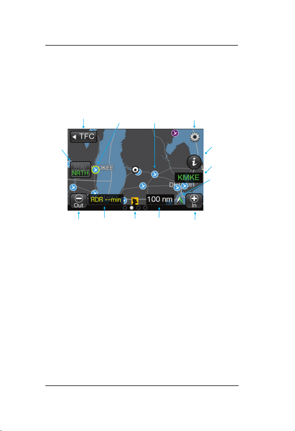
Operation - Panel Mount
Out
Indicator
Stamp
Orientation
Indicator
Lynx ® NGT-9000
FIS-B Graphical Weather Application
The Graphical Weather Application is located in the second screen
position (or third screen position when TAWS is enabled, Release
2.0 or greater) as indicated by the Application Indicator. The Graphic
Application is a simplied moving map with depiction of ownship and
the ability to selectively overlay graphical FIS-B products such as,
NEXRAD, METAR, and SIGMET. See Figure 2-14.
Time
Selected
Symbol
No Coverage
Airport
Symbol
Display Range
Options Button
Information
Button
Selected Airport
ID Indicator
North
Indicator
Zoom
Traffic Button
Button
Zoom
Figure 2-14: Weather Map
Map Elements
FIS-B weather products are overlaid on the map. The viewing of
weather products is controlled by the declutter range selected on the
Options Screen.
• Tap to select Product overlaid map elements.
• The selected map elements are highlighted in a yellow outline.
• A tap of an empty area of the map de-selects the map element.
• Only one map element can be selected at a time and may be
selected when panning is active or not.
• The map is normally centered on the ownship symbol when
panning is not activated. When panning is active the viewing area
is repositioned to that selected by the pilot.
• The directional ownship symbol is a white triangle that is a reference
point that corresponds to the ownship position.
• The ownship symbol is a white circle if direction data is not
known.
Pilot’s Guide2-40
Page 63

Lynx ® NGT-9000
• The land masses are black. Bodies of water are dark blue. Depiction
of NEXRAD weather radar data is overlaid on the map. Map areas
where NEXRAD data has not been received are indicated using
a gray semi-transparent graphical overlay. This will cause land
masses to appear grey and water to appear light blue. When no
graphical NEXRAD data is available.
• Country and State borders are solid light gray lines.
• Major roads are depicted as solid gray lines for display ranges less
than or equal to 200 nm.
• Cities are shown on the map in small white text centered on the
cities location. The display ranges of cities are dependent on the
size of the city as follows: Large and medium sized cities are shown
at less than or equal to 200 nm. Small cities are shown at less than
or equal to 50 nm.
• The symbol for the different types of airports are described in Table
2-5. Soft surfaced airports are shown at display ranges less than or
equal to 10 nm. Hard surfaced small airports are shown at display
ranges less than or equal to 20 nm. Hard surfaced large airports
are shown at display ranges less than or equal to 200 nm.
Operation - Panel Mount
Information Button (i)
The Information button is shown on the screen, located on the right
side of the screen, after a map element is selected. The button is
gray in color and labeled with an “i” icon. Tap the button to show the
Weather Map Text screen on the left side of the screen.
TFR Map Elements
Temporary Flight Restrictions are displayed on the map as a solid red
line. A TFR is shown as a solid orange line up to 12 hours prior to the
effective date and time of the TFR.
AIRMET and SIGMET Map Elements
AIRMET and SIGMET are weather advisories with concise descriptions
of weather conditions in an area. The AIRMET are used for less
severe weather then the SIGMET. The type and graphic description
are detailed below:
Pilot’s Guide 2-41
Page 64

Operation - Panel Mount
Lynx ® NGT-9000
Table 2-5: Airport Symbols
DESCRIPTION SYMBOL
Towered Soft Surfaced Airport
Non-towered Soft Surfaced Airports
Towered Hard Surfaced Small Airports
(1,500 to 8,069 ft runway)
Non-towered Hard Surfaced Small Airports
(1,500 to 8,069 ft runway)
Towered Hard Surfaced Large Airports
(> 8,069 ft runway and some multi-surfaced < 8,069 ft
runways)
Non-towered Hard Surfaced Large Airports
(> 8,069 ft runway and some multi-surfaced < 8,069 ft
runways)
AIRMET TYPE DISPLAY PROPERTIES
Icing Straight hashed blue line
Turbulence Straight hashed orange line
Mountain Obscuring Straight hashed magenta line
IFR Straight hashed purple line
Unknown Straight hashed blue line
SIGMET TYPE DISPLAY PROPERTIES
Icing
Turbulence
Convective
Volcanic Ash
Other
Straight hashed Red line
Pilot’s Guide2-42
Page 65

Lynx ® NGT-9000
Operation - Panel Mount
METAR
METAR is a report of weather conditions at airports represented
graphically and consists of the FAA Flight Rules and Weather
Conditions. The ight rules icons shows the FAA ight rules for each
airport based on the visibility and cloud cover conditions. The weather
conditions icons indicates the weather conditions at each airport based
on precipitation, winds, and visual obstructions. The type and graphic
description are detailed below:
FLIGHT RULES DISPLAY PROPERTIES
VFR Filled cyan circle
MVFR Filled green circle
IFR Filled yellow circle
LIFR Filled magenta circle
Unknown Filled grey circle
NEXRAD Map Elements
NEXRAD provides data on precipitation and its intensity in the form
of a composite mosaic image. See Figure 2-15. NEXRAD information
extends to approximately a 75 nm radius of the ownship, and is only
updated every 5 minutes. Note - Freezing precipitation colors (pink/
blue) are not provided.
The age of the NEXRAD data is shown in the lower left corner of the
screen with yellow text. The time stamp is labeled with “RDR” and
“min”. Dashes replace the time stamp when no NEXRAD image data
is available. (The actual age of the data can be 0 to 20 minutes older
than indicated.)
CONUS Map Elements
CONUS information covers the Continental United States. It is only
updated every 15 minutes.
Figure 2-15: Example of NEXRAD Weather Map
Pilot’s Guide 2-43
Page 66

Operation - Panel Mount
Lynx ® NGT-9000
Trafc Button
This button is located on the far left side of the screen and is labeled
“TFC” with a left facing triangle. Tap the button to return to the Trafc
Application screen.
Zoom Buttons
Zoom In (+) and Zoom Out (-) buttons are located on the bottom of
screen. The buttons are used to change the display range shown on
the display. Display range options for the Graphic Application screen
are 10 (minimum), 20, 50, 100, 200, 400, and 800 (maximum).
Display Range Indicator
This indication is a readout of the selected display range and is located
in the lower right corner of the display.
Panning
Press and hold an area of the screen that is not a button for 1 second
to activate the Panning function. Drag across the map to move the
map in that direction. Tap the Cancel Pan button to inactivate the
panning function.
North Indicator
This indication is a white/green arrow located in the lower right corner
of the display. The indicator points to the top of the display when
the application is oriented north up and points true north when the
application is oriented track up.
Airport ID Indicator
The airport ID is shown on the screen, located below the Information
button, after an airport map element is selected.
Orientation Button
This toggle button is located on the left side of the screen is labeled
“Map”. The button has two selections “NRTH” which is north up and
“TRK” which is track up. The lower half of the button shows the current
map orientation in green text.
The north up orientation has the ownship position in the center of the
map screen.
The track up orientation has the ownship centered horizontally but
moved down to the lower one third of the screen (this orientation
provides a longer look ahead in the direction of travel).
The map defaults to North Up orientation if ownship position data is
not valid.
Pilot’s Guide2-44
Page 67

Lynx ® NGT-9000
Operation - Panel Mount
Map Options Button
The gear shaped Options Button is located in the upper right corner of
the map screen. Tapping the button opens the Options screen that has
three latch buttons located on the bottom of the screen. These buttons
are labeled ON/OFF, Declutter, and Done.
Tap the Done button to close the Options Screen.
On/Off Option Screen
The ON/OFF screen has Toggle On/Off buttons for the FIS-B products
and a Legend. A green LED indicates that the button and function is
On. See Figure 2-16.
Figure 2-16: On/Off Options Screen
Weather Map Legend Screen
The Legend screen is located on the left screen and is shown after
the Legend button in the On/Off screen is tapped. The screen has a
banner on the top of the screen above the left display area. See Figure
2-17.
Banner
The Banner is shown on the top of the screen having a gray background.
The banner provides the following information:
• Done button used to return to the previous screen.
• Mode A squawk code indicator.
• Reply “R” or Ident “ID” indicator shown to the right of the squawk
code when either function is active.
• Current transponder operating mode status indicator with green
text. An amber “Fail” is shown the transponder function as failed.
Pilot’s Guide 2-45
Page 68

Operation - Panel Mount
Lynx ® NGT-9000
Figure 2-17: Weather Map Legend Screen
Pilot’s Guide2-46
Page 69

Lynx ® NGT-9000
Operation - Panel Mount
Display Area
The left display area is used to show the meaning of map elements
provided by FIS-B products. It is identied with the label “Legend”.
A scroll bar on the right side provides an indication that additional
information can be seen by using an up/down drag action.
Declutter Option Screen
The declutter screen has a banner at the top of the screen that is
labeled with the declutter range scale from 10 to 800.
The Declutter setting sets the zoom range when a product is displayed/
removed from the display.
The display area shows the declutter list of the different products
(NEXRAD, METAR, TFR, AIRMET, and SIGMET). LED indicators
show declutter ranges for each product. The selected list item is
highlighted in white. Use the Zoom buttons to increase and decrease
the layer range. Use a slide action to scroll up and down the product list.
The example in Figure 2-18 would indicate that NEXRAD information
would be displayed up to the 400 nm range.
Figure 2-18: Declutter Option Screen
Weather Map Text Screen
The Weather Map Text is shown on the left screen after the Information
button is tapped. The screen is removed from view when another
application is activated on the right screen or if the selected map
element is deselected. See Figure 2-19.
Pilot’s Guide 2-47
Page 70

Operation - Panel Mount
Time: 19 June 18:54 UTC
Wind: From 320 at 04KT
Gusts: None
Visibility: 10 Mile
Weather: No significant weather
Ceiling: 100000 ft AGL
Lynx ® NGT-9000
Figure 2-19: Weather Map Text Screen
Display Area
The left display area is used to show text report data from the selected
map element.
Banner
The Banner is shown on the top of the left screen having a gray
background The banner provides the following information:
• Done button used to remove the Weather Map Text screen and
return the left side application screen.
• Mode A squawk code.
• Reply “R” or Ident “ID” indicator shown to the right of the squawk
code when either function is active.
• Current transponder operating mode status indicator with green
text. An amber “Fail” is shown the transponder function as failed.
• Product Select button opens a Product Select window. The button
is displayed only when the selected display element is an airport.
See Figure 2-20.
If selected product text data report is not available, the display area
indicates this by displaying the selected product with a “not available”
message.
Product Select List Window
The window shows a list of product types to select. Tapping the item
will select the product type. Only one product type can be selected at
a time. The available product are METAR, TAF, and NOTAM. Use a
slide action to scroll the window up and down. Tap the item in the list
to select. A selected item is indicated by a green indicator.
Tap the Done button to close the window and return to the Weather
Map Text screen. The selected product will now be displayed on the
Weather Map Text screen. If data for that product type is not available,
the message “not available” is displayed.
Pilot’s Guide2-48
Page 71

Lynx ® NGT-9000
Traffic Button
In
Button
Operation - Panel Mount
Figure 2-20: Product Pick List Window
FIS-B Graphic Winds & Temp Application
The Graphical Winds and Temperature Application is available on the
right screen and is located in the third screen position (4th screen
position when TAWS installed, Release 2.0 or greater) as indicated
by the Application Indicator. This application screen displays graphical
wind and temperature aloft information obtained from FIS-B products.
The aloft map orientation is shown as north up. See Figure 2-21.
Trafc Button
This button is located on the far left side of the screen and is labeled
“TFC” with a left facing triangle. Tap the button to return to the Trafc
Application screen.
Cancel Pan Button
Zoom
Flight Level
Selection
North
Indicator
Aloft
Zoom
Out
Time
Stamp
Ownship Symbol
Display Range
Indicator
Figure 2-21: Aloft Map Screen
Pilot’s Guide 2-49
Page 72

Operation - Panel Mount
The winds aloft display properties are dened in Figure 2-22.
Lynx ® NGT-9000
Figure 2-22: Winds Aloft Map Elements
Pilot’s Guide2-50
Page 73

Lynx ® NGT-9000
Operation - Panel Mount
Aloft Button
This button is located on the left side of the screen and is labeled
“Aloft” with white text and the active selection labeled either “Wind”
or “Temp” with green text. Tap the button to select the other screen
function.
Panning
Press and hold an area of the screen that is not a button for 1 second
to activate the Panning function. Drag across the map to move the
map in that direction. Tap the Cancel Pan button to inactivate the
panning function.
Zoom Buttons
Zoom In (+) and Zoom Out (-) buttons are located on the bottom of
screen. The buttons are used to change the display range shown on
the display. Display range options are 10, 20, 50, 100, 200, 400, and
800.
Issue Valid Time Indication
This indicator is located at the bottom of the screen and is shown with
green text when a valid time is shown. The text is shown with yellow
text when the data is not valid or available.
Ownship Symbol
The ownship is shown as a white triangle when heading or track is
valid. When ownship direction source is not valid the ownship symbol
is a white circle with a black inset.
North Indicator
This indication is a white/green arrow located in the lower right corner
of the display. The indicator points to the top of the display when the
application is oriented north up.
Flight Level Selection
This is a vertical array of altitudes which is shown when the altitude is
pressed. Selection is done by tapping the screen on the value desired.
The values are in hundreds of feet.
When transitioning from one region to the other and the currently
selected ight level is not supported in the new region, the selected
ight level is reset to one that is supported.
Pilot’s Guide 2-51
Page 74

Operation - Panel Mount
Traffic
Area
T
Lynx ® NGT-9000
FIS-B Textual Application
The Textual Application is available on the right screen and is located
in the fourth screen position as indicated by the Application Indicator.
This application screen displays textual weather information products
for selected airports provided by FIS-B. The products available are
METAR, TAF, NOTAM. See Figure 2-23.
Display Area
The display area is used to show text report data from the selected
Product.
Favorites
Button
Product
Button
Display
ext Report
Data
Button
Airport
Button
Location: ABC1
Day of month: 28
Time: 19:15 UTC
Wind: 360 @ 6 kts
Gusting to 0 kts
Visibility: 1 mile
Figure 2-23: FIS-B Textual Application
Banner
The banner is located above the display area. The banner contains
buttons to return to the Trafc Application screen, open the Edit Airport
ID window, open the Favorites Pick List window, and a button to open
the Product Pick List window.
Trafc Button
This button is located on the far left side of the banner and is labeled
“TFC” with a left facing triangle. Tap the button to return to the Trafc
Application screen.
Banner
Pilot’s Guide2-52
Page 75

Lynx ® NGT-9000
Operation - Panel Mount
Airport Button
This button is located to the right of the Trafc button is labeled with
the Selected Airport identier. This information is also shown below in
the display area. Tap the button to open the Edit Airport ID window.
Edit Airport ID Window
This window is used to enter an Airport ID that is shown on the airport
button and the display. See Figure 2-24.
• Use the keyboard to enter the three or four character alphanumeric Airport ID in the airport edit box
• Tap the Cancel button to close the window without changing the
current Airport ID.
• Tap the Add to Favorites button (star plus icon) to add the current
Airport ID to the Favorites Pick List. The Favorites Pick List has
maximum of 50 entries. The button is inhibited when the pick list
has reached its maximum.
• Tap the Done button to close the window and set the selected
airport ID.
If a selected airport is not found in the navigation database, an “Airport
not found” message is shown in the display area.
Figure 2-24 Example of Edit Airport ID Window
Pilot’s Guide 2-53
Page 76

Operation - Panel Mount
Lynx ® NGT-9000
Favorites Button
This button is labeled with a amber star icon. Tap the button to open
the Favorites Pick List window.
Favorites Pick List Window
This window is used to select a pre-saved Airport ID. See Figure 2-25.
• The Favorite Airports list is centered in the display area showing
the list of airports set by the user via the add to favorite button
located in Edit Airport ID window. The list has a maximum 50
entries organized alphabetically. Use a slide action to scroll the
list. Tap an ID from the list to select it.
• Tap the Done button to return to close the window and set the
selected airport ID.
• Tap the Delete button to remove the selected airport ID from the
favorites list.
• Tap the Cancel button to close the window without changing the
current Airport ID.
Figure 2-25: Example of Favorites Window
Pilot’s Guide2-54
Page 77

Lynx ® NGT-9000
Operation - Panel Mount
Product Button
This button is labeled with the current selected product. Tap the button
to open the Product Pick List window.
Product Pick List Window
This window is used to select an available FIS-B Textual Product,
which are METAR, NOTAM , and TAF. See Figure 2-26.
• The Product List is centered in the display area showing the list of
available Products. Tap the product from the list to select it.
• Tap the Done button to return to close the window and set the
Product.
If selected product text data report is not available, the display area
indicates this by displaying the selected product with a “not available”
message.
Figure 2-26 Example of Product Pick List Window
Pilot’s Guide 2-55
Page 78

Operation - Panel Mount
Lynx ® NGT-9000
TAWS OPERATION
The Terrain Awareness and Warning System (TAWS) is an optional
function that is set up during installation. The TAWS function
continuously monitors the aircraft’s position, altitude, speed, track, and
phase of ight and compares the information to the terrain database
loaded during installation. Terrain and obstacle hazards are indicated
by cautions and warnings using screen annunciators, aural terrain
alerts, and discrete alert lamps. See Figure 2-27 and the descriptions
below for details.
The details for the TAWS Screen at the beginning of this section is for
the Panel Mount version of the Lynx NGT-9000. The instructions for
TAWS Audio Alerts (page 2-64) and Conditions to Trigger Alerts or
Callouts (page 2-65 to page 2-73) are for both the Panel and Remote
Mount versions of the Lynx NGT-9000.
Release 2.1 or greater. A conguration option is available that sets the
unit to show terrain only with no audio alerts.
Figure 2-27: TAWS Screen
Pilot’s Guide2-56
Page 79

Lynx ® NGT-9000
Operation - Panel Mount
Limitations
• The TAWS function shall not be used as a navigation instrument. It
is not intended to provide navigational guidance nor to relieve pilots
from following published navigational procedures, routes, altitude
restrictions, and/or instructions from air trafc control agencies
except in response to alerts to avoid potentially hazardous terrain
and/or obstacles. The terrain screen is intended to serve as a
situational awareness tool only.
• Terrain elevation recorded in the database refers to the actual
ground or water; it does not include trees, shrubs, or ice.
• TAWS does not operate in north of 70° N or south of 70° S.
• TAWS will use all airport runways included in the database. Contact
Jeppesen® if a runway is not included in the database.
Defining Terrain Alerts
A caution alert as an alert that requires immediate pilot awareness
and corrective action usually necessary involving stop descending
or initiate either a climb or a turn, or both as necessary, based on
analysis of all available instruments and information.
A warning alert as an alert that requires immediate pilot action to initiate
and continue a climb that will provide maximum terrain clearance, or
any similar approved vertical terrain escape maneuver, until all alerts
cease. Vertical maneuvers are only recommended, unless either
operating in visual meteorological conditions (VMC), or the pilot
determines, based on all available information, that turning in addition
to the vertical escape maneuver is the safest course of action, or both.
Traffic Button
This button is located on the far left side of the screen and is labeled
“TFC” with a left facing triangle. Tap the button to return to the Trafc
Application screen.
Zoom Buttons
Zoom In (+) and Zoom Out (-) buttons are located on the bottom of
screen. The buttons are used to change the display range shown on
the display. Display range options for the Graphic Application screen
are 2 (minimum), 6, 12, and 24 (maximum) nmi.
Pilot’s Guide 2-57
Page 80

Operation - Panel Mount
Lynx ® NGT-9000
Display Range Indicator
This indication is a readout of the selected display range and is located
in the lower right corner of the display.
Display Orientation Indicator
The display orientation indicator is located on the lower left side of the
screen and is shown as either, No indication (default installed direction
source of heading or track), a white/green chevron indicating NorthUp orientation, or has the letters “TRK” indicating the installed heading
source has failed and the GPS track is now being used.
The display orientation indicator is not shown during normal operation.
Installations with heading will have a default display orientation of
heading up. Installations without heading will have a default display
orientation of track up.
When installations without heading are on the ground with no valid
track information, the screen reverts to north up depiction and indicates
the north chevron.
When installations with heading source have a heading failure, if track
is valid, the screen will revert to track up and indicate “TRK”. If track is
invalid (sitting on ground), then the screen will be north up.
Aural Acknowledge Button
This button is shown on the right side of the screen when a terrain
caution or warning alert occurs. Tap the button to silence the aural part
of the current terrain alert. The button is then removed from the screen
until another alert occurs.
AGL Altitude Readout
The Above Ground Level Altitude readout is located in the top right of
the screen. The readout has a upper limit of 9,950ft. The readout is
removed from the screen if the altitude is > 10,000ft or when sitting on
the ground (0 ft AGL).
Pilot’s Guide2-58
Page 81

Lynx ® NGT-9000
Operation - Panel Mount
Ownship Symbol
The ownship symbol is a white triangle when the display orientation is
direction-up (true heading or true track-up are valid) and is centered
horizontally, but moved down to the lower one third of the screen. An
ownship velocity vector line uses ownship track and ground speed to
indicate 30 seconds of ownship travel.
The ownship symbol is a black/white circle when the display orientation
is north-up and is located in the center on the screen.
Obstacle Symbols
Obstacles are depicted as triangular shape objects that can be either
small or tall; colored as either cyan, yellow, or red; and shown as a
single object or as a group. Obstacles are shown when the display
range is 2, 6, and 12 nmi.
A small obstacle is shown for obstacles that are 200ft to <1,000ft tall.
Tall obstacles are shown for obstacles that are > 1,000ft. Obstacles
that are < 200ft are not shown on the TAWS screen.
Obstacle color is based on obstacle elevation (MSL altitude at the
top of the obstacle) compared to the aircraft altitude. Cyan colored
obstacles are > 1,000ft below the aircraft. Amber colored obstacles are
between 1ft and 1,000ft below the aircraft, and red colored obstacles
are equal to or above the aircraft altitude.
NOTE
While obstacles are enabled, TAWS is capable of
generating alerts on all obstacles included in the database.
However, due to incomplete obstacle data and display decluttering techniques such as altitude ltering and obstacle
coalescing, every obstacle may not be depicted on the
Terrain Display.
Pilot’s Guide 2-59
Page 82

Operation - Panel Mount
Lynx ® NGT-9000
Airport Symbols
The symbol for the different types of airports are described in Table
2-5. Airport symbols are shown on the screen when the display range
is 12 nmi or less.
Airport Symbol Operation
Tap the symbol to display the Airport Identier and the Information
button on the right side of the screen.
Tap the Information Button to open the TAWS Airport Text screen.
It’s operation is identical to the “Weather Map Text Screen”. Refer to
Figure 2-20 on page 2-49.
Tap an area of the screen without an airport symbol to deselect. The
airport symbol is also deselected when the distance between the
airport symbol and ownship is > 35 nmi.
Table 2-5: Airport Symbols
DESCRIPTION SYMBOL
Towered Soft Surfaced Airport
Non-towered Soft Surfaced Airports
Towered Hard Surfaced Small Airports
(<8,069 ft runway)
Non-towered Hard Surfaced Small Airports
(<8,069 ft runway)
Towered Hard Surfaced Large Airports
(> 8,069 ft runway)
Non-towered Hard Surfaced Large Airports
(> 8,069 ft runway
Estimated Quiet Zone Around Airport Symbols
on the TAWS display the 1.2 nmi radius gray-shaded area depicted
around each airport symbol is the estimated quiet zone. It is used as a
visual reminder that TAWS does not igenerate predictive alerts in the
area near airport runways.
Pilot’s Guide2-60
Page 83

Lynx ® NGT-9000
The TAWS system has a predictive terrain alert “or quiet zone” around
each airport runway to help reduce nuisance alerts during a normal
takeoff or landing procedures. GPWS-type alerts such as ‘excessive
descent rate’, however, are still active and will alert in this area.
Note that the predictive alert suppression is related to the location of
the alert, not the position of the aircraft. Aircraft within a quiet zone
may still predict alerts on terrain or obstacles outside the quiet zone.
See the ‘forward looking terrain avoidance (F LTA)’ section for more
information on quiet zones.
Operation - Panel Mount
TAWS Terrain Color Legend
Each color represents a terrain elevation in relation the aircraft’s current
altitude. Table 2-6 shows color samples at 500 ft steps. The system
provides a smooth color transition to changing terrain elevations and
aircraft altitudes.
Table 2-6 Terrain Color Scheme
Pilot’s Guide 2-61
Page 84

Operation - Panel Mount
Lynx ® NGT-9000
Information Button (i)
The Information button is shown on the screen, located on the right
side of the screen, after a airport symbol is selected. The button is
gray in color and labeled with an “i” icon. Tap the button to show the
TAWS Airport screen on the left side of the screen.
TAWS Airport Text Screen
The TAWS Airport Text screen is used to show text report data from
the selected airport symbol the same as the FIS-B Textual Products
Page. See Figure 2-28.
The screen is removed from view when another application is activated
on the right screen or if the selected airport symbol is deselected.
Figure 2-28: TAWS Airport Text Screen
The top portion of the screen is a gray stripped banner that provides
the following information and operation:
• Tap the Done button remove the TAWS Airport Text screen and
return the left side application screen.
• Display of the Mode A squawk code.
• Reply “R” or Ident “ID” indicator shown to the right of the squawk
code when either function is active.
• Display of the current transponder operating mode status indicator
with green text. An amber “Fail” is shown the transponder function
as failed.
• Product Select button opens a Product Select window. Refer to
Figure 2-21. The available product are METAR, TAF, and NOTAM.
If the selected product text data report is not available, the display
area indicates this by displaying the selected product with a “not
available” message.
Pilot’s Guide2-62
Page 85

Lynx ® NGT-9000
Operation - Panel Mount
TAWS Options Button
The gear shaped Options Button is located in the upper right corner
of the right application screen. Tap the button to open the options
screen. Refer to Figure 2-29.
Figure 2-29: TAWS Options Screen
TAWS Options Screen
The Settings latch button opens a screen providing the setting of
Obstacles and Alerting status. Both buttons may be set to “Enabled”
or “Inhibited”. Both buttons are set to “Enabled at start-up.
• Selecting “Inhibited” on the Obstacles button removes obstacles
from the TAWS display and TAWS will not include obstacles as
part of the alert detection. This is used to stop TAWS alerting when
landing at an unknown airport or runway.
• Selecting “Inhibited” on the Alerting button places an “Inhibited”
indicator on the screen and removes visual TAWS alerts and stops
aural alerts from occurring.
Tap the Done button to close the Options Screen.
TAWS Display Alerts
When a TAWS Caution or Warning Alert is detected, the appropriate
alert symbol is depicted at the location of the alert on the terrain map.
Red or Amber Alert Text indicators which relate to the active TAWS
Alert are shown at the bottom center of the screen. Refer to Figure
2-28 and Table 2-7. The display alert is accompanied by an aural
announcement.
The TAWS Inhibited indicator is shown when Alerting is inhibited using
the TAWS options Screen.
Pilot’s Guide 2-63
Page 86

Operation - Panel Mount
Table 2-7: TAWS Display Alerts
TAWS Warning Symbol
TAWS Caution Symbol
TAWS Warning Text
TAWS Caution Text
TAWS Caution Obstacle Text
TAWS Inhibited
Lynx ® NGT-9000
TAWS Audio Alerts
Aural announcements for caution alerts are repeated every 7 seconds
and require immediate ight crew awareness and possible action. The
exact phrase used in the aural announcement depends on the installation setup, the type of alert condition, and whether the alert is due to
terrain or an obstacle. See Table 2-8.
Aural announcements for warning alerts are repeated continuously
and require immediate ight crew action. The exact phrase used in
the aural announcement depends on the installation setup, the type of
alert condition, and whether the alert is due to terrain or an obstacle.
See Table 2-8.
500 ft Altitude Callout
The 500 ft altitude callout consists of the aural announcement, “ve
hundred.” The callout is intended to provide situational awareness
to the ight crew and does not necessarily indicate a hazardous
condition.
Pilot’s Guide2-64
Page 87

Lynx ® NGT-9000
Table 2-8: Caution & Warning Alert Phrases*
ALERT
CONDITION
Reduced
Required Terrain Clearance (RTC)
(Figure 2-32)
or
Imminent Terrain Impact (ITI)
Figure 2-33)
Premature
Descent
(Figure 2-34)
Excessive
Descent Rate
(Figure 2-35)
Negative
Climb Rate or
Altitude Loss After Takeoff
(Figure 2-36)
Controls and Indicators
CAUTION
ALERT
PHRASES
“Caution, Terrain;
Caution, Terrain!”
Or
“Caution, Obstacle;
Caution, Obstacle!”
“Terrain Ahead;
Terrain Ahead!”
Or
“Obstacle Ahead;
Obstacle Ahead!”
“Too Low, Terrain!” None
“Sink Rate!” None
“Don’t sink!”
“Too low, terrain!”
Warning
Alert
Phrases
“Terrain, Terrain;
Pull Up, Pull Up!”
“Obstacle, Obstacle;
Pull Up, Pull Up!”
“Terrain Ahead,
Pull Up;
Terrain Ahead,
Pull Up!”
“Obstacle, Obstacle;
Pull Up, Pull Up!”
None
Or
Or
* The primary or secondary phrase options are setup at installation.
Conditions to Trigger Alerts or Callouts
The TAWS function uses Forward Looking Terrain Avoidance (FLTA)
and Ground Proximity Warning System (GPWS) functionality to
determine when a terrain alert or altitude callout is triggered due
based on the following conditions:
• Reduced required terrain clearance (FLTA)
• Imminent terrain impact (FLTA)
• Premature descent
• Excessive descent rate (GPWS)
• Negative climb rate or altitude loss after takeoff (GPWS)
• Altitude of 500 ft (GPWS)
Pilot’s Guide 2-65
Page 88

Controls and Indicators
Look-Ahead Distance
(60 Seconds)
Look-Down Distance
(Required Terrain
Clearance)
Terrain
Terrain
Width of the search volume increases
linearly from 0.25 nmi at the plane, to
0.5 nmi 60 seconds ahead of the plane,
and increases even more around turns.
Note that turns are only "predicted"
based on the current turn rate.
Lynx ® NGT-9000
Forward Looking Terrain Avoidance (FLTA)
The conditions, reduced required terrain clearance and imminent
terrain impact, are part of the TAWS FLTA function. Using FLTA, TAWS
looks ahead of the airplane (in the database) along its projected vertical
and horizontal ight path, including turns, to determine if any terrain
or obstacles might pose a threat (Figure 2-30). (Hereafter, the word
“terrain” refers to “terrain or obstacles” unless indicated otherwise.)
The TAWS function determines the terrain threat based on the phase
of ight (Figure 2-31) and on the predicted terrain clearance compared
to the required terrain clearance (Tables 2-9 & 2-10). FLTA alerts are
disabled within the quiet zone when landing the aircraft to prevent
nuisance terrain alerts. The quiet zone is an area 1.2 nm around the
runway and 700 ft above the runway threshold.
Figure 2-30: Forward Looking Terrain Avoidance (FLTA)
Figure 2-31: Phase of Flight Definitions
Pilot’s Guide2-66
Page 89

Lynx ® NGT-9000
Operation - Panel Mount
Reduced Required Terrain Clearance (RTC)
The reduced RTC alert condition (Figure 2-32) occurs when the
aircraft is currently above the altitude of the upcoming terrain along
the projected ight path, but the projected terrain clearance is less
than the required terrain clearance (Table 2-9).
The TAWS function issues a caution alert 60 seconds before the
offending terrain and a warning alert 30 seconds before the offending
terrain.
“Terrain, terrain; pull up, pull up!”*
“Caution, terrain; caution, terrain!”*
Required Terrain
Clearance
Figure 2-32: Reduced RTC Alert Condition
Table 2-9: Required Terrain Clearances for the
TERRAIN
Caution
Alert
60 sec
PULL UP
Warning
Alert
30 sec
Projected Terrain Clearance
Reduced RTC Alert Condition
Pilot’s Guide 2-67
Page 90

Operation - Panel Mount
Caution
Alert
60 sec
30 sec
Warning
Alert
Required Terrain
Clearance
Projected Terrain
Clearance
“Caution, terrain; caution, terrain!”*
“Terrain, terrain; pull up, pull up!”*
TERRAIN
PULL UP
Lynx ® NGT-9000
Imminent Terrain Impact (ITI)
The ITI alert condition (Figure 2-33) occurs when your aircraft is
currently below the altitude of the upcoming terrain along the projected
ight path, and the projected terrain clearance is less than the required
terrain clearance (Table 2-10).
The TAWS function issues a caution alert 60 seconds before the
offending terrain and a warning alert 30 seconds before the offending
terrain.
Figure 2-33: ITI Alert Condition
Table 2-10: Required Terrain Clearances for the ITI Alert Condition
Phase of Flight
Enroute 700 ft
Terminal
Approach
Departure
Required Terrain Clearance
350 ft
150 ft
100 ft
Pilot’s Guide2-68
Page 91

Lynx ® NGT-9000
Operation - Panel Mount
Premature Descent
The premature descent alert condition (Figure 2-34) occurs when
your aircraft is signicantly below the normal nal approach ight path
to the nearest runway (typically a 3-degree implied glideslope). This
condition may exist for a variety of reasons such as poor visibility
or nighttime operation. If this condition is not corrected, then likely
the aircraft will touch down short of the runway even if the aircraft is
properly congured for landing and is descending at a normal rate. The
premature descent alert is only enabled in the terminal and approach
phases.
The TAWS function uses the aircraft’s current position, ight path
information, and the runway database to detect the premature descent
condition and then a caution alert is sent.
TAWS function calculates premature descent alerts
based on the aircrafts proximity to the closest runway
WARNING
and measures the aircrafts distance from that runway
once per second. The closest runway may or may not be
the runway intended for a landing.
700 ft
Normal Final Approach
350 ft
Caution Alert:
“Too low, terrain!”
TERRAIN
15 nm
Premature Descent
12 nm
5 nm
150 ft
2 nm 1 nm
Nearest
Runway
1
nm
2
Figure 2-34: Premature Descent Alert Condition
Pilot’s Guide 2-69
Page 92
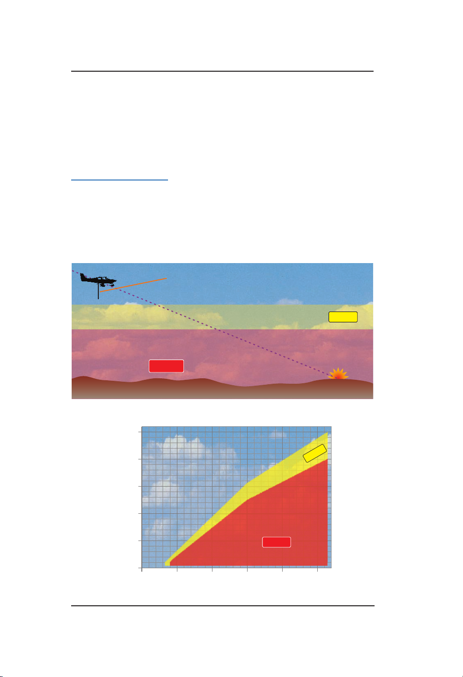
Operation - Panel Mount
Height Above Terrain (ft)
Descent Rate (fpm)
Lynx ® NGT-9000
Ground Proximity Warning System (GPWS) Alerting
The alert and callout conditions for excessive descent rate, negative
climb rate or altitude loss after takeoff, and altitude of 500 ft are
determined by the TAWS function subtracting the terrain elevation
stored in its terrain database from the GPS-based aircraft altitude to
calculate height above terrain.
Excessive Descent Rate
The excessive descent rate alert condition (Figure 2-35), also known
as GPWS Mode 1, occurs when the aircraft is descending too fast for
the aircrafts current height above terrain, regardless of the aircrafts
ap position. More precisely, it’s when your aircraft’s descent rate and
height above terrain fall within the envelopes shown in Figure 2-36.
The aircrafts descent rate determines the
height at which alerts begin to occur.
Caution Alert:“Sink Rate!”
TERRAIN
Warning Alert:
“Pull up!”
PULL UP
Figure 2-35: Excessive Descent Rate Alert Condition
5,000
4,000
3,000
2,000
1,000
CautionAlert:
“Sink Rate!”
Warning Alert:
“Pull up!”
PULL UP
0
2,000 4,000 6,000 8,000 10,0000
TE RRA IN
Figure 2-36: Excessive Descent Rate Graph
Pilot’s Guide2-70
Page 93

Lynx ® NGT-9000
Operation - Panel Mount
Negative Climb Rate or Altitude Loss After Takeoff
These alert conditions (Figure 2-37), also known as GPWS Modes
3A and 3B are enabled between 50 and 700 ft above the runway
after takeoff or after a missed approach. The negative climb rate alert
condition is based on descent rate. The altitude loss after takeoff
alert condition is based on accumulated altitude loss in order to catch
descents that are too gradual to qualify for the negative climb rate alert
condition. The two together ensure that practically any descent after
takeoff or missed approach will trigger an alert.
“Don’t sink!”
or
“Too low, terrain!”
TERRAIN
Caution Alert
700 ft
Runway
Figure 2-37: Negative Climb Rate or
Altitude Loss After Takeoff Alert Condition
50 ft
Pilot’s Guide 2-71
Page 94

Operation - Panel Mount
Height Above Runway (ft)
Descent Rate (fpm)
Height Above Runway (ft)
Altitude Loss (ft)
Lynx ® NGT-9000
When the aircraft’s height above the runway elevation and its descent
rate or altitude loss fall within the envelopes shown in gures 2-38 and
2-39, TAWS issues a caution alert.
700
600
500
Caution Alert:
“Don’t sink!”
400
300
200
100
“Too low, terrain!”
0
1,000 2,000 3,000 4,000 5,000 7,0006,0000
or
TERRAIN
Figure 2-38 Negative Climb Rate Graph
700
600
500
400
300
200
100
0
20 40 60 80 100 1200
Caution Alert:
“Don’t sink!”
or
“Too low, terrain!”
TERRAIN
Figure 2-39: Altitude Loss After Takeoff Graph
Pilot’s Guide2-72
Page 95

Lynx ® NGT-9000
Operation - Panel Mount
Altitude of 500 ft
This condition (Figure 2-40), also known as a subset of GPWS Mode
6, occurs when the aircraft descends within 500 ft of the terrain
during enroute mode, or when the aircraft is in enroute mode in level
ight but the terrain below rises up within 500 ft of the aircraft. It also
occurs when the aircraft descends within 500 ft of the nearest runway
threshold elevation during terminal or approach mode. When any of
these conditions occurs, TAWS issues an aural 500 ft altitude callout
(“ve hundred”). The 500 ft altitude callout does not occur when the
aircraft is ascending or during departure or missed approach mode.
The callout is ready to play again only after the aircraft ascends to 700
ft above the terrain or runway.
“Five Hundred”
500ft
“Five Hundred”
500ft
Figure 2-40: Altitude of 500 Feet Callout Condition
Pilot’s Guide 2-73
Page 96

Operation - Panel Mount
Lynx ® NGT-9000
LIGHTNING OPERATION
Lightning detection is an optional function that is set up during
installation. The Lightning function continuously monitors electrical
discharges from thunderstorms within a 200 nmi radius of the aircraft
and plots the location of the discharges as cells or strikes on the right
application screen. See Figures 2-41 and 2-42 and the descriptions
below for details.
Refer to the Stormscope (WX-500) Users Guide 009-11501-001 for
in-depth details.
Figure 2-41: Lightning Screen 360 View
Never use the Lightning system to attempt to penetrate
a thunderstorm. The FAA Advisory Circular, Subject:
WARNING
Thunderstorms, and the Airman’s Information Manual
(AIM) recommend that aircraft are to “avoid by at least 20
miles any thunderstorm identied as severe or giving an
intense radar echo.”
Traffic Button
This button is located on the far left side of the screen and is labeled
“TFC” with a left facing triangle. Tap the button to return to the Trafc
Application screen.
Pilot’s Guide2-74
Page 97

Lynx ® NGT-9000
Figure 2-42: Lightning Screen 120 View
Operation - Panel Mount
Ownship Symbol
The ownship symbol is a white triangle with the nose of the ownship
symbol corresponding to the ownship position.
• When the View mode is 360 the symbol is centered on the screen.
See Figure 2-41.
• When the View mode is 120 the symbol is centered at the bottom
of the screen. See Figure 2-42.
Zoom Buttons
Zoom In (+) and Zoom Out (-) buttons are located on the bottom of
screen. The buttons are used to change the display range shown on
the screen. Display range options for the Lightning screen is 25, 50,
100, and 200 nmi.
360 View
Display range 25 NM has a white outer circle with Azimuth indicators
at 30 degree intervals. See Figure 2-41.
Display range 50, 100, and 200 has Azimuth indicators at 30 degree
intervals in an outer ring. An inner white circle surrounds the Ownship
that represents 25 nmi from the Ownship.
120 View
Display range 25 NM has a white outer arc with Azimuth indicators at
+ / - 30 degree with white radial lines extending from the nose of the
ownship symbol. See Figure 2-42.
Display range 50, 100, and 200 has Azimuth indicators at +/- 30 and
+/- 60 degrees with white radial lines extending from the nose of the
ownship symbol. An inner white arc extends from the +/- 60 radial
lines that represents 25 nmi from the Ownship.
Pilot’s Guide 2-75
Page 98
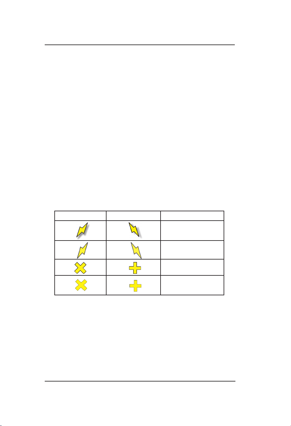
Operation - Panel Mount
Lynx ® NGT-9000
Mode Button
This toggle button is located on the left side of the screen and is labeled
“MOD”. The button has two selections “STK (strike) and “CEL” (cell).
The lower half of the button shows the current mode selection in green
text. Refer to Table 2-11 for Lightning Symbology.
• Set the mode for Strike to display strike data on the screen. Strike
data is most useful during periods of light electrical activity as this
will show the strengthening thunderstorm sooner then cell data.
• Set the mode for Cell to display cell data on the screen. Cell data
is used during heavy electrical activity.
Note - Other atmospheric phenomena can cause isolated discharge
points in the Strike Mode screen. Clusters of two or more discharge
points do indicate thunderstorm activity when they reappear after
clearing the screen.
In the Cell Mode screen even a single discharge point may represent
thunderstorm activity and should be avoided.
Table 2-11: Lightning Symbols
STRIKE CELL STRIKE AGE
0-10 sec
10 sec - 1 min
1-2 min
2-3 min
Clear Button
This button is located on the far right side of the screen and is labeled
“CLR”. Tap the button to clear the screen of the current lightning data
(strike or cell).
Clearing the lightning data periodically helps in determining if a storm
is strengthening or dissipating. A strengthening storm is indicated by
the lightning data reappearing faster and in larger numbers, while a
dissipating storm appears slower and with fewer number of strikes.
Pilot’s Guide2-76
Page 99

Lynx ® NGT-9000
Operation - Panel Mount
Lightning Options Button
The gear shaped Options Button is located in the upper right corner
of the right application screen. Tap the button to open the Lighting
Setting page. Refer to Figure 2-43.
Lightning Settings (View Mode, Stabilization, Status)
The Settings page is active when “Settings” label is green. The page
shows the WX-500 software information, WX-500 Status information,
current display View and Stab (stabilization) status.
• The View Mode toggle button can be set for either 120 or 360
degrees.
• The Stab Mode toggle button can be set for either On or Off.
When set to “On” the position of the electrical discharge points
on the display are automatically adjusted as the aircraft changes
heading. Stab should always be “On” except for system without a
heading source or if heading is invalid.
It is recommended that Stabilization be set to “Off” if heading is
invalid and remain off until heading input is corrected. When set
to Off the heading indicator is not displayed and a “STAB OFF”
message is shown on the screen.
• Along with the software information the status of the WX-500
is indicated as “OK”in white text, “Degraded” in amber text, or
“Failed” in red text. If degraded or failed is shown a fault code
and description is shown. Multiple codes will rotate one at a
time for 3 second periods. A list of error messages and fault
information is provided in the WX-500 User’s Guide (009-11501-
001).
Press the Done button to return to the lightning application screen.
Note - The Tests page is used for installation of the WX-500 and
should be ignored.
Figure 2-43: Lightning Setting Page
Pilot’s Guide 2-77
Page 100

Operation - Panel Mount
Lynx ® NGT-9000
Heading Stabilization
The heading stabilization automatically adjusts the position of the
discharge points on the screen when the aircraft changes heading.
• This feature is not available for aircraft with out a heading input or
if heading data is invalid.
• If heading data is invalid as indicated by amber dashes shown for
the heading indicator, then stabilization should be set for Off using
the Lighting Options page.
• If heading stabilization is Off tap the “CLR” button to clear the
discharge points after each heading change to display new
discharge points in the proper location relative to the nose of the
aircraft.
Strike Rate Indicator
The Strike Rate Indicator is located in the upper right corner of the
screen and is labeled “RATE”. The indicator shows the approximate
number of strikes per minute providing the user a way to determine if
thunderstorms are strengthening or weakening.
Strike Rate Trend Arrow
This white arrow is shown to the left of the Rate Indicator. When the
arrow is shown pointing up it indicates an increase in strikes while a
down pointing arrow indicates a decrease in strikes.
Heading Indicator
The heading indicator is located on the top right side of the screen and
provides a three digit (001 to 360) display of heading.
If heading is invalid the digits are replaced with three amber dashes
and heading stabilization is off.
Note - Heading is optional and this indicator will not be shown if
heading is not used.
Application Indicator / Nearby Strike
The Application Indicator is located on the bottom of the screen. It
shows the current application screen (lightning) compared to the other
enabled application screens.
A Nearby Strike Indication is shown over the lightning application dot .
It fades in/out when active to draw attention to possible storm activity.
See Figure 2-42.
Pilot’s Guide2-78
 Loading...