

Page 1
/<1;56HULHV
6HFXULW\6\VWHPV
,QVWDOODWLRQDQG6HWXS*XLGHIRU
/<1;5/<1;5DQG/<1;5(1
OFF
AWAY
STAY
AUX
®
K5963 5/01
®
Page 2

RECOMMENDATIONS FOR PROPER PROTECTION
The Following Recommendations for the Location of Fire and Burglary Detection Devices Help Provide Proper Coverage
for the Protected Premises.
Recommendations for Smoke and Heat Detectors
With regard to the number and placement of smoke/heat detectors, we subscribe to the recommendations contained in the
National Fire Protection Association's (NFPA) Standard #72 noted b e low.
Early warning fire detection is best achieved by the installation of fire detection equipment in all rooms and areas of
the household as follows: For minimum protection a smoke detector should be installed outside of each separate sleeping
area, and on each additional floor of a multi-floor family living unit, including basements. T he installation of smoke
detectors in kitchens, attics (finished or unfinished), or in garages is not normally recommended.
For additional protection the NFPA recommends that you install heat
room, bedroom(s), kitchen, hallway(s), attic, furnace room, utility and storage rooms, basements and attached garages.
or smoke detectors in the living room, dining
In addition, we recommend the following:
• Install a smoke detector inside every bedroom where a smoker sleeps.
• Install a smoke detector inside every bedroom where someone sleeps with the door partly or completely closed.
Smoke could be blocked by the closed door. Also, an alarm in the hallway outside may not wake up the sleeper if the
door is closed.
• Install a smoke detector insid e bedrooms where electrical appliances (such as po rtable heaters, air conditioners or
humidifiers) are used.
• Install a smoke detector at both ends of a hallway if the hallway is more than 40 feet (12 meters) long.
• Install smoke detectors in any room where an alarm control is located, or in any room where alarm control
connections to an AC source or phone lines are made. If detectors are not so located, a fire within the room could
prevent the control from reporting a fire or an intrusion.
THIS CONTROL COMPLIES WITH NFPA REQUIREMENTS FOR TEMPORAL
PULSE SOUNDING OF FIRE NOTIFICATION APPLIANCES.
KITCHEN
DINING
LIVING ROOM
BEDROOM
BEDROOMBEDROOM
LIVING
ROOM
BEDROOM
BASEMENT
KTCHN
TO
BEDROOMBEDROOM
BEDROOM
CLOSED
.
DOOR
TV ROOM
BEDROOM
Smoke Detectors for Minimum Protection
Smoke Detectors for Additional Protection
Heat-Activated Detectors
GARAGE
KITCHEN
DINING
LIVING ROOM
BEDROOM
BEDROOM
01000-002-V0
Recommendations For Proper Intrusion Protection
For proper intrusion coverage, sensors should be located at every possible point of entry to a home or premises. This would
include any skylights that may be present, and the upper windows in a multi-level building.
In addition, we recommend that radio b ackup be used in a securit y system. This will ensure that alarm signal s can be sent to
the alarm monitoring station in the event that the telephone lines are out of order (alarm signals are normally sent over the
phone lines, if connected to an alarm monitoring station).
–2–
Page 3

Table of Contents
SYSTEM FEATURES....................................................................................................................... 4
MOUNTING THE CONTROL ......................................................................................................... 5
WIRING CONNECTIONS................................................................................................................ 6
AC POWER AND BACKUP BATTERY.........................................................................................9
INSTALLING WIRELESS ZONES................................................................................................ 11
MECHANICS OF PROGRAMMING............................................................................................. 14
ZONE RESPONSE TYPE DEFINITIONS...................................................................................... 15
DATA FIELD DESCRIPTIONS.....................................................................................................17
*56 ENHANCED ZONE PROGRAMMING MODE ..................................................................... 24
*80 DEVICE PROGRAMMING MENU MODE ........................................................................... 29
*81 ZONE LIST MENU MODE..................................................................................................... 32
*83 ENHANCED SEQUENTIAL MODE ...................................................................................... 33
*84 ASSIGN ZONE VOICE DESCRIPTORS................................................................................ 35
*85 RECORD CUSTOM VOICE DESCRIPTORS ........................................................................ 37
REMOTE PROGRAMMING/CONTROL (DOWNLOADING).................................................... 38
SYSTEM OPERATION .................................................................................................................. 39
TESTING THE SYSTEM................................................................................................................ 44
SYSTEM COMMUNICATION ...................................................................................................... 45
TROUBLESHOOTING GUIDE...................................................................................................... 47
REGULATORY AGENCY STATEMENTS.................................................................................. 49
SPECIFICATIONS.......................................................................................................................... 50
LYNXR/LYNXR24 PROGRAMMING DEFAULT TABLES....................................................... 51
LYNXR-EN PROGRAMMING DEFAULT TABLES................................................................... 52
INDEX............................................................................................................................................. 55
LIMITATIONS OF THIS SYSTEM STATEMENT....................................................................... 57
WARRANTY................................................................................................................................... 58
SUMMARY OF CONNECTIONS DIAGRAM.............................................................................. 59
–3–
Page 4
System Features
LYNXR and LYNXR-EN are not intended for UL985 Household Fire applications
8
/
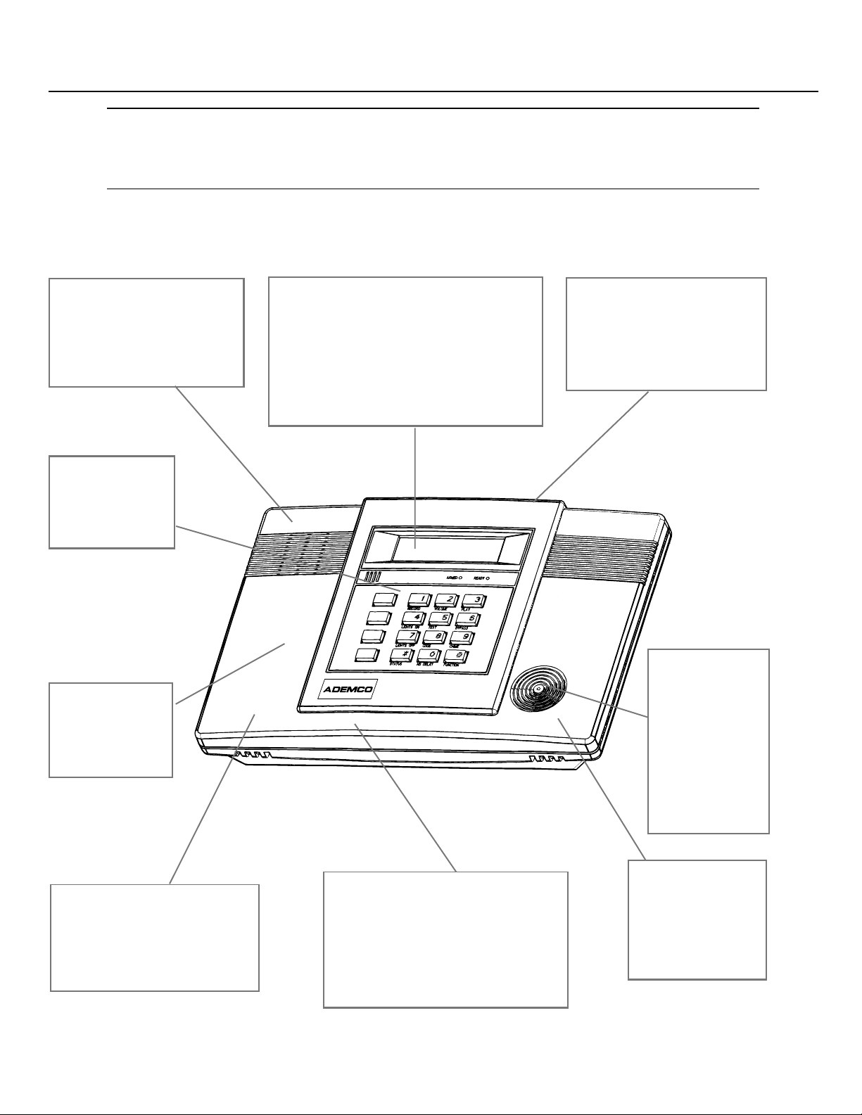
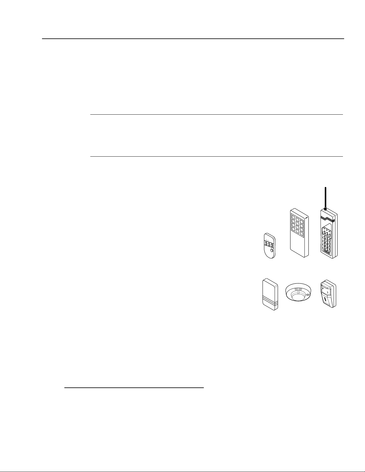
The LYNXR-Series controls are self-contained, rechargeable wireless control/communicators that feature easy installation
and usage. A built-in speaker provides voice annunciation of system status along with voice descriptors of each zone
(LYNXR-EN if programmed). The following illustration highlights the main features of this system.
ZONES and DEVICES
•
1 hardwire zone
•
Up to 24 wireless zones
(5800 Series Transmitters)
•
Up to 16 wireless button zones
•
Up to 8 Powerline Carrier Devices
•
Supports wireless keypads
8 USER CODES
•
Installer code
•
Master code
•
5 Secondary codes
•
Duress code
•
3 Panic functions
unless a 24-hour backup battery (P/N LYNXRCHKIT-HC) is installed.
Powerline Carrier Devices are not UL Listed for fire or burglary functions and are intended
for home automation.
FEATURES
•
Real-time Clock display and Fixed-Word display
•
Message Center (for user recorded messages)
•
Voice announcement of system and zone status
•
Voice chime
•
Alarm Clock
•
Reminder
•
X-10 Scheduling
•
Latch Key Reports
•
Automatic Stay Arming
•
•
SYSTEM POWER
Primary Power: Ademco
1332/1332X10 Plug-in Transformer,
110VAC to 9VAC, 15VA output
(1332CN in Canada)
Backup battery: Six 1.2V
rechargeable nickel-metal hydride
batteries.
COMMUNICATION
•
Ademco Low Speed
•
Sescoa/Radionics
•
Ademco Express
•
Ademco Contact ID
•
Paging feature
PROGRAMMING
•
Options stored in EEROM
•
Can be uploaded, downloaded or
controlled via IBM-compatible
computer using Compass downloader
software and specified HAYES
modem
OFF
AWAY
STAY
AUX
®
OTHER FEATURES
•
Exit error feature (detects difference between
an actual alarm and exit alarm caused by
leaving a door open after the exit delay
expires)
•
Event log stores up to 84 events
•
Macro/ 1-button paging
•
RF Jam Detection
•
Remote phone control
ALARM OUTPUT
•
Built-in sounder
•
Piezo output
(30mA max.)
•
Bell output
(120mA max.)
•
Steady output for
burglary/panic
•
Temporal pulse
output for fire alarms
•
Long Range
Radio/Alarm audio
Verification
SPECIAL FEATURES
LYNXR24
•
24-hour backup
LYNXR-EN
•
Two-way voice
communication
•
Speaker phone
operation
–4–
Page 5
Mounting the Control
Wall Mounting
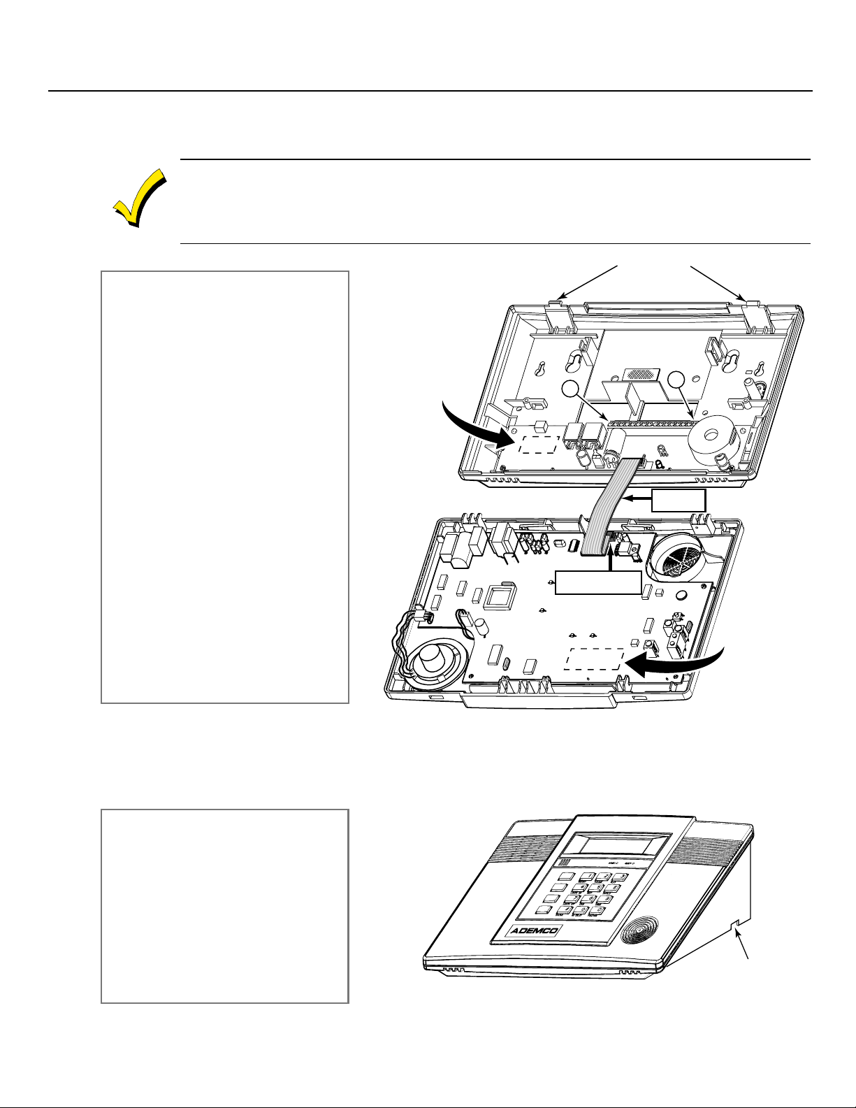
The illustration below shows the front asse mbly separated from the back plate.
DO NOT disconnect the ribbon cable from the terminal strip board. Disconnect the cable only from
the front assembly board.
Certain features differ between the LYNXR/LYNXR24 and the LYNXR-EN models. Verify the specific
model being installed prior to programming the system.
LOCKING TABS
1.
Separate the front assembly from the
back plate by pressing on the two
locking tabs at the top of the unit.
2
. Carefully disconnect the ribbon cable
from the front assembly,
ribbon cable connected to the
terminal block PC board
plate contains the terminal block for
leaving the
. The back
PC BOARD
PART NUMBER
LOCATION
1
16
MXXXX
K5108
making wiring connections.
3.
Mount the back plate to a sturdy wall,
feeding the field wiring through the
appropriate openings in the back plate.
4.
After wiring connections are made,
carefully reconnect the ribbon cable to
RED WIRE
MARKING
the front assembly PC board connector
(properly aligning the red wire).
5.
Before closing the assembly, verify
which LYNXR model is being installed
DISCONNECT
THIS END ONLY!
by checking the model number printed
on the PC Boards. (Example:
SALYNXREN indicates the unit being
installed is a LYNXR-EN.)
6.
Snap the front assembly to the back
plate so it is held by the locking tabs.
PC BOARD
PART NUMBER
LOCATION
01009-003-V0
Desktop Mounting
If desired, an optional mounting base (model LYNX-DM, purchased separately) allows the LYNXR-Series controls to be
used on a desktop.
1.
2.
3.
Use the two supplied screws to secure
Slide the control panel onto the
mounting base locking tabs
Bring all wiring through the bottom of
the mounting base, using one of the
three wire entry locations, before
making connections to the control
panel.
Use tie-wraps to secure the wiring to
the built-in wire loops as needed.
the control panel to the mountin
.
g base.
OFF
AWAY
STAY
AUX
®
WIRE ENTRY
KNOCKOUT
(1 of 3)
01000-004-V0
–5–
Page 6
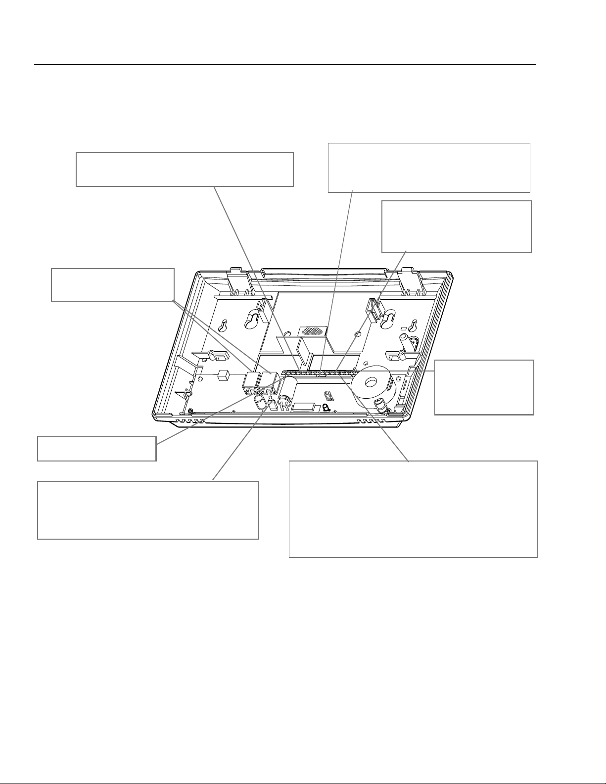
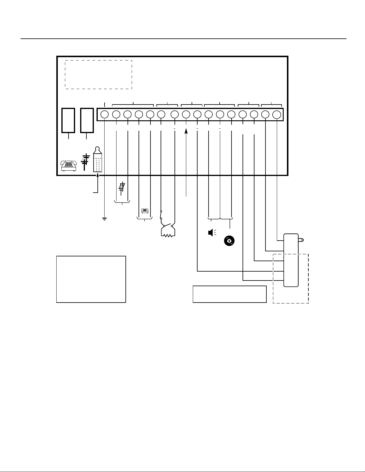
Wiring Connections
Wiring Overview
The following summarizes the connections required. Refer to the Wiring Connections paragraph and the Summary of
Connections diagram on the inside back cover when making connections.
Use either the plug-in jacks or the
screw terminals.
Supports 1 EOLR supervised zone using either closed circuit
or open circuit sensors.
HARDWIRE ZONE
PHONE LINES
Compatible with ALARMNET 7845C and 7720
LONG RANGE RADIO
Devices. LYNXR and LYNXR24 are compat ible with
the LYNXAVM.
POWERLINE CARRIER DEVICES
Supports up to 8 Powerline Carrier
Devices for turning on/off lights and
appliances. Requires the use of an
ADEMCO 1332X10 transformer.
MXXXX
K5108
AC TRANSFORMER
Use the supplied ADEMCO
1332X10 9VAC, 15VA
Plug-in Transformer
(1332CN in Canada).
01009-005-V0
EARTH GROUND
See Earth Ground paragraph.
LOCAL SOUNDER DISABLE JUMPER
Remove the shorting jumper (shunt) to disable local sounder,
leaving only the external sounder active.
UL NOTE:
Do not remove the shorting jumper (the shunt) for
UL installations.
The system includes a built-in sounder in the master keypad. If
desired, an external bell or piezo sounder can be connected.
Bell:
Use a 6-14V bell with maximum current drain of 120mA.
Piezo:
Use a 6-14V piezo sounder with maximum current drain of
30mA.
This control complies with NFPA requirements for temporal pulse
sounding of fire notification appliances.
Temporal pulse sounding for a fire alarm consists of the following: 3
pulses – pause – 3 pulses – pause – 3 pulses. . .
SOUNDERS
Wiring Connections
1. Make Earth Ground Connection
for the lightning transient protective devices in this product to be effective. The following are examples of good earth
grounds available at most installations:
Metal Cold Water Pipe - Secure a noncorrosive metal strap (copper is recommended) to the pipe that is electrically
connected and secured to which the ground lead.
AC Power Outlet Ground - Available from 3-prong, 120VAC power outlets only. To test the integrity of the ground
terminal, use a three-wire circuit tester with neon lamp indicators, such as the UL Listed Ideal Model 61–035, or
equivalent, available at most electr ica l supp ly stores.
a. Connect terminal 1 to a good earth ground.
-
The designated earth ground terminal (1) must be terminated in a good earth ground
–6–
Page 7
Wiring Connections
Wiring Connections
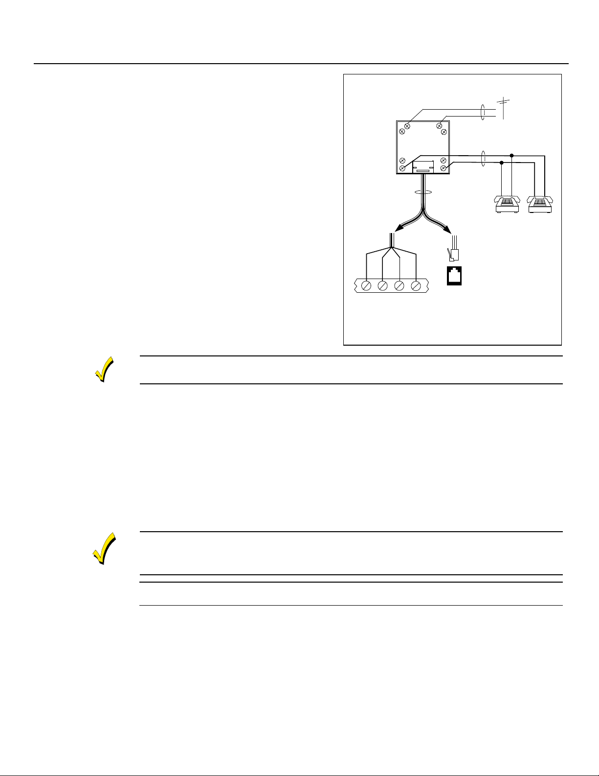
2. Make Phone Line Connections
seizure proceed to the appropriate steps below.
Local Seizure
a. Connect the incoming phone line to either the
8-position jack or terminals 2 (TIP) and 3 (RING).
b. Connect the handset phone lines to either the RJ11
jack or terminals 4 (TIP) and 5 (RING).
Full Line Seizure
with the incoming phone line. Plugging the Direct
Connect Cord directly into the RJ31X jack, allows the
control to seize the phone line when an alarm occurs
and normal phone line usage by the premises phones if
the plug needs to be removed.
a. Cut the incoming RING and TIP phone lines
(typically red and green, respectively) and connect
them to RJ31X terminals 4 (red) and 5 (green).
b. Connect the premises end of the cut RING and TIP
wires to RJ31X terminals 1 (grey) and 8 (brown)
respectively.
c. Wire the flying leads of a Direct Connect Cord to the
control’s phone terminals as shown in the diagram
or plug into the 8-position jack.
d. Plug the Direct Connect Cord into the RJ31X jack.
HARDWIRED ZONE: If the EOLR is not at the end of the loop, the zone will not be properly
supervised, and the system may not respond to an open circuit on the zone.
3. Make Hardwired Zone Connections -
circuit devices and has a response time of 350msec. Maximum zone resistance: 300 ohms, plus EOLR
Note: The hardwire zone cannot be used as a fire zone.
a. Connect sensors/contacts to the hardwired zone terminals 6 (+) and 7 (–). Refer to the Summary of Connections
diagram.
b. Connect closed circuit devices in series in the high (+) side of the loop. The EOL resistor must be connected in
series with the devices, following the
c. Connect open circuit devices in parallel across the loop. The 2000-ohm EOLR must be connected across the loop
at the last device.
4. Make External Sounder Connections -
6-14VDC bell (120mA max.; e.g. ADEMCO WAVE2EX).
a. Connect a piezo sounder to terminals 10 (+) and 11 (–); OR a bell to terminals 11 (–) and 12 (+).
LOCAL SOUNDER DISABLE: The Master Keypad’s built-in piezo sounder can be disabled by
removing the shorting jumper (shunt) on the terminal board. If disabled, however, no sounding
8/
will occur upon AC loss, since the external sounder does not operate when AC power is lost.
Do not remove shorting jumper (the shunt) for UL installations.
- For local or full line
: The control must be placed in
Zone 1 is an EOLR supervised zone that supports both open circuit and closed
last device.
The control panel supports either a 6-14VDC piezo sounder (30mA max.) or
series
INCOMING
PHONE LINE
RING
TIP
6
7
8
DIRECT
CONNECT
CORD
8-POSITION
JACK
GREENRED
PREMISES PHONES
RING
TIP
BROWN
TO
01000-008-V0
45
3
RJ31X
2
GREY
RED
1
BROWN
}
TO
PREMISES
PHONES
OR
OR
GREY
GREEN
TIP RING TIP RING
}
INCOMING
PHONE LINE
Full Line Seizure Connections
5. Disable Local Sounder Option
a. Remove the shorting jumper (shunt) on the terminal board.
6. Make Powerline Carrier Device Connections -
- If required the Master Keypad’s built-in piezo sounder can be disabled.
The control panel supports up to 8 Powerline Carrier Devices. If using
these devices, they must be connected to the ADEMCO 1332X10 transformer, as shown in the SUMMARY OF
CONNECTIONS diagram.
a. Connect the com/data/sync/ lines from the ADEMCO 1332X10 transformer to terminals 9, 13, and 14, respectively.
Note: If not using the supplied Ademco connection cable, you may need to reverse the black and yellow wire connections. Refer
*80 Device Programming Menu Mode
to the
section for details on programming Powerline Carrier Devices.
–7–
Page 8
Wiring Connections
TO PREVENT RISK OF SHOCK
DISCONNECT TELEPHONE LINE
RJ11
TO
HANDSET
PHONE
LINE
LOCAL SOUNDER
DISABLE SHUNT
REMOVE TO
THE LYNX SERIES CONTROLS ARE
EQUIPPED WITH AN INTEGRAL
RECHARGEABLE BATTERY PACK.
LYNXR: P/N LYNXRCHKIT-SC
LYNXR24: P/N LYNXRCHKIT-HC
LYNXR-EN: P/N LYNXRCHKIT-SC
OR
P/N LYNXRCHKIT-HC
REPLACE EVERY FOUR YEARS
WARNING:
AT TELECOM JACK BEFORE
SERVICING THIS UNIT .
EARTH
GROUND
8
POS
JACK
INCOMING
PHONE
LINE
DISABLE
GROUND
1
EARTH
2
TIP
INCOMING
TELEPHONE
LINE
PHONE
3
4
TIP
RING
RING
PREMISES
TELEPHONE
WEEKL Y TESTING IS
REQUIRED TO ENSURE
PROPER OPERATION
OF THIS SYSTEM
ALL OUTPUT CIRCUITS ARE POWER LIMITED.
AAV / LRR
TRIGGER
(LYNXR/LYNR24)
LRR
TRIGGER
EOLR
(LYNXR-EN)
7
TRIGGER
SIGNAL
(NEG)
SOUNDERS
12
865
9
( )
USE ONLY 1332/1332X10 OR 1332CN
11
10
(+)( )
( )
(+)
PIEZO
BELL
6-14VDC
30mA max.
TRANSFORMERS PROVIDED
6-14VDC
120mA max.
(e.g. W AVE2EX)
NOTE
ZONE
(+)
HARD
WIRED
ZONE
2k OHMS
PLCD
14
13
DATA
SYNC
OUT
IN
POWERLINE
CARRIER DEVICES
AC
15
16
1332/
1332X10/
1332CN
PLUG-IN
TRANSFORMER
9VAC, 15VA
AC
AC
SYNC
COM
DATA
1332X10
ONLY
CONNECTIONS
01009-009-V0
–8–
Page 9
AC Power and Backup Battery
The system is powered by a 9VAC, 15VA Plug-in Transformer, ADEMCO 1332/1332X10 (1332CN in Canada). Refer to
the wiring table below for wire gauge and length.
Distance from Transformer
Use only the provided ADEMCO
1332/1332X10 or 1332CN Transformer
to Control
Up to 75 feet #20
75 to 150 feet #18
150 to 300 feet #16
Wire Gauge
Wiring to the AC Transformer must not exceed 300 feet using 16-gauge wire. The voltage reading between
terminals 15 and 16 of the control must not fall below 9.00VAC.
Do not plug the transformer into the AC outlet until after all wiring connections have been made.
Backup battery.
In the event of an AC power loss, the system is supported by a long life backup battery that is supervised for
connection and for low voltage conditio ns. If the battery is missing, or a low battery condition is detected, a “low battery”
message is displayed and a report is sent to the central station. In addition, the system will beep once every 45 seconds to
audibly indicate a low battery condition (p ress any key to stop the beeping).
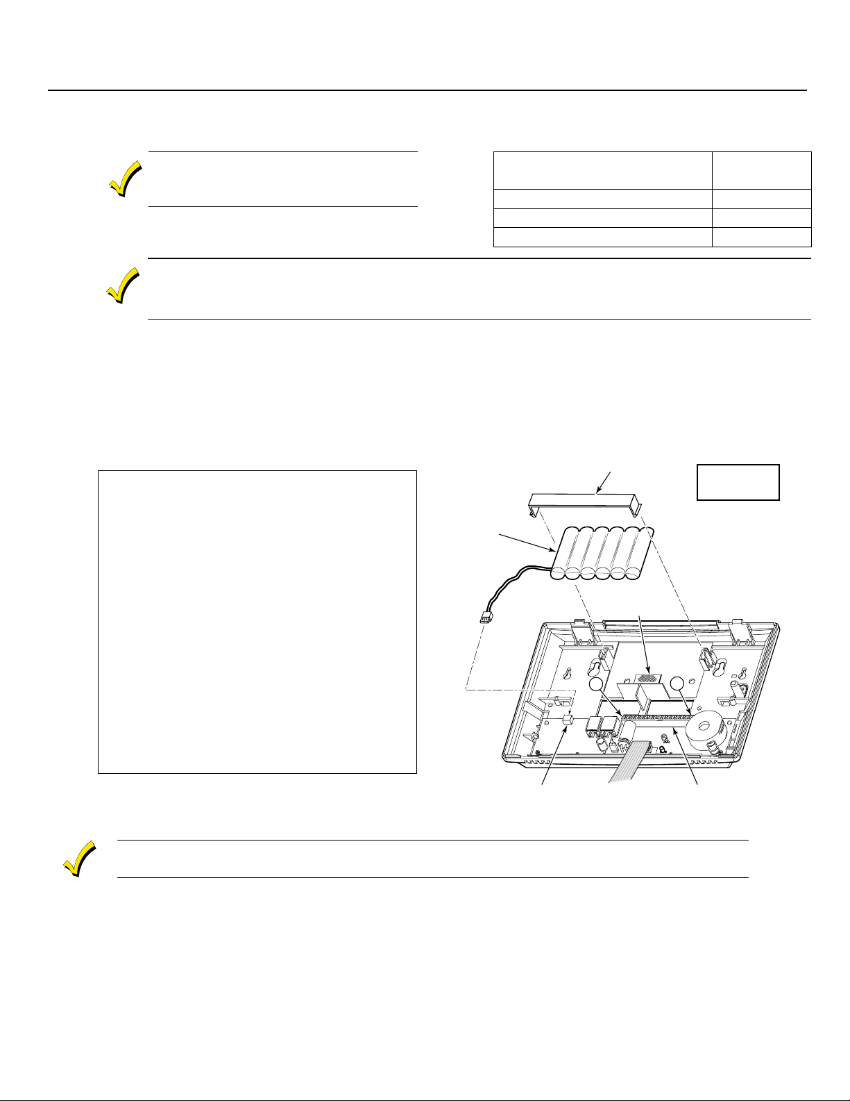
AC Power and Rechargeable Backup Battery
Connecting AC Power and backup battery
1.
Connect wires from the 1332/1332X10 (1332CN in
Canada) AC Transformer to terminals 15 and 16
as shown in the wiring diagram.
2.
Remove battery retainer.
3.
Peel the backing from tape on the back plate.
4.
Insert battery pack into back plate.
5.
Install battery retainer.
6.
Connect battery connector to receptacle on
terminal block PC board.
7.
After all wiring connections have been made, snap
the front assembly to the back plate and plug the
transformer into a 24-hour, 110VAC unswitched
outlet.
8.
Rechargeable batteries may take up to 48-hours to
fully charge. The “LOW BAT” message should
clear within four hours or by entering Test Mode.
BATTERY
PACK
BATTERY
RECEPTACLE
RETAINER
1
TAPE
16
WIRING
TERMINALS
NOTE
LYNXRCHKIT-HC
BATTERY PACK SHOWN
MXXXX
K5108
01009-007-V0
Ensure the cover is snapped closed prior to applying AC power.
–9–
Page 10
AC Power and Backup Battery
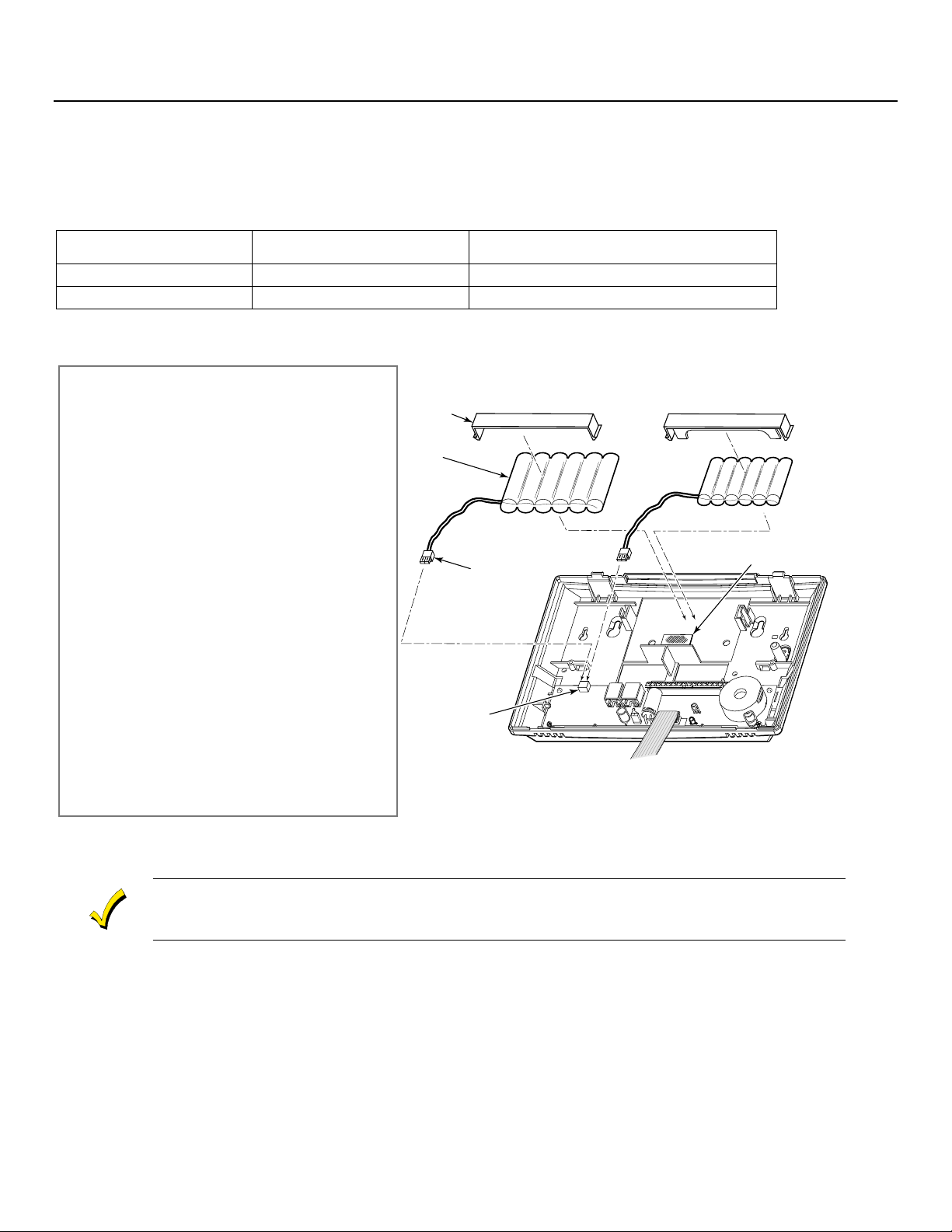
AC Power and Rechargeable Backup Battery
The LYNXR Series is equipped with an integral, replaceable, rechargeable battery pack composed of six (6) rechargeable
1.2-volt nickel-metal hydride batteries. Select the appro priate battery pack, based on the installation’s requirement, and install
the battery pack.
Model/Part Number
LYNXRCHKIT-SC 4-hours (minimum) Approximately 1-hour before battery depletion
LYNXRCHKIT-HC 24-hours (minimum) At least 1-hour before battery depletion
Battery StandbyTime
Replacing the Rechargeable Battery
1.
When battery replacement is required, unplug
the transformer from the wall outlet, and open
the control panel cover.
2.
Remove the battery retainer and disconnect the
battery pack connector from the receptacle on
the terminal block PC board.
3.
Remove the battery pack from the back plate.
4.
If required, replace the tape that secures the
battery pack.
5.
Install a replacement battery pack (P/N
LYNXRCHKIT-SC or LYNXRCHKIT-HC) into the
back plate.
6.
Install the battery retainer.
7.
Connect the battery connector to the receptacle
on the terminal block PC board.
8.
After the wiring connection has been made, snap
the front assembly to the back plate.
9.
Plug the transformer into a 24-hour, 110VAC
unswitched outlet.
10.
Rechargeable batteries may take up to 48-hours
to fully charge. The “LOW BAT” message should
clear within four hours or by entering Test Mode.
Low Battery Notification
LYNXRCHKIT-HC OR LYNXRCHKIT-SC
BATTERY
CONNECTOR
TAPE
MXXXX
K5108
01009-006-V0
RETAINER
BATTERY
PACK
BATTERY
RECEPTACLE
Ensure the control panel assembly is snapped closed prior to applying AC power.
–10–
Page 11
Installing Wireless Zones
General Information
Zones: The control supports up to 24 wireless zones using 5800 Series transmitters, and up to 16 wireless buttons.
Range: The built-in RF receiver can detect signals from wireless transmitters within a nominal range of 200 feet.
Transmitters: 5800 Series transmitters have built-in serial numbers that must be entered into the system using the
*
56 or *83 interactive mode, or input to the control via the downloader. 5800 Series transmitters (except the 5800RL
and 5827, described separately) do not have DIP switches. Each transmitter's zone number is programmed into the
system in
loops or inputs). On the 5816, for example, the wire connection terminal block is loop 1, the reed contact is loop 2.
Each loop must be assigned a different zone number.
8
For button transmitters (RF "keys") such as the 5804 and 5801, you must assign a unique zone number to each
individual button used on the transmitter. Each button on the transmitter also has a pre-designated loop or input
number, which is automatically displayed.
House Identification
If you are using a 5804BD/5804BDV, 5827, or 5827BD Wireless Keypad
with the system, you must program a House ID Code (01–31) in field
establish proper communicatio n, and the keypad must be set to the sa me ID.
House ID 00 disables all wireless keypads. An RF House ID is not necessary
for other 5800 Series transmitters; the entry should be left at “00” (default) in
those cases. The 5827 reports low battery status as zone “00”.
Transmitter Supervision
Except for some transmitters/keypads that may be carried off-premises
(5804, 5804BD, 5804BDV, 5804E, 5804WATCH, 5827 and 5827BD), each
transmitter is supervised by a check-in signal that is sent to the receiver at
70–90 minute intervals. If at least one check-in is not received from each
supervised transmitter within a 12-hour period, the "missing" transmitter
number(s) and "FAULT" will be displayed. The supervision for a particular
transmitter in the system that may also be carried off the premises (5801,
5802MN) may be turned off by entering it as a "UR" (unsupervised RF) type,
as described in the
5800 Series transmitters have built-in tamper protection and will annunciate
as a fault condition if covers are removed.
Note: The 5804E and 5804WATCH transmitters are only supported by the
Transmitter Input Types
All of the transmitters described have one or more unique factory-assigned input (loop) ID codes. Each of the inputs
requires its own programming zone (e.g., a 5804's four inputs require four button zones).
Transmitters can be entered as one of the following types (see transmitter’s instructions for approp riate input type):
Type Description
"RF" (Supervised RF)
"UR" (Unsupervised RF)
"BR" (Unsupervised Button RF)
*
56 mode. Some transmitters, such as the 5816 and 5817, can support more than one "zone" (referred to as
The 5816 and 5817 Transmitters do not have EOL supervision of their loop wiring. Therefore, for
UL Household Burglary installations, the loop wiring may not exceed 3 feet.
/
The 5800RL, 5802MN, 5802MN2, 5804, 5804BD, 5804BDV, 5804E, 5804WATCH, 5814, 5816TEMP,
5819, 5819S(WHS & BRS), 5827BD, and 5850(GBD) transmitters are not intended for any UL
installations.
*
24 to
1
2
4
3
5
7
6
8
*
9
0
#
•
•
•
•
•
•
•
•
•
•
•
•
•
•
•
•
•
•
•
5827 5827BD5804BD/5804BDV
*56 Enhanced Zone Programming Mode
section.
5806/5807/5808 5890 / 5890PI5816
LYNXR-EN.
Sends periodic check-in signals, as well as fault, restore, and low battery signals.
The transmitter must remain within the receiver's range.
Sends all the signals that the "RF" type does, b ut the control does no t supervise
the check-in signals. The transmitter may therefore be carried off-premises.
These only send fault signals. They do not send lo w ba ttery signals until they are
activated. The transmitter may be carried off-premises.
1
2
3
4
5
6
7
8
9
*
0
#
01009-010-V0
–11–
Page 12

Installing Wireless Zones
Transmitter Battery Life
• Batteries in the wireless transmitters may last from 4–7 years,
depending on the environment, usage, and the specific wireless device
being used. Factors such as humid ity, high or low te mperatures, as
well as large swings in te mperature may all reduce the actual batter y
life in a given installation. T he wireless s ystem ca n identi fy a true lo w
battery situation, thus allowing the dealer or user of the system time to
arrange a change of battery and maintain protection for that point
within the system.
• Button-type transmitters should be periodically tested for battery life.
The 5801, 5802MN, 5802MN2, 5804, 5804BD, 5804BDV, 5804E,
and 5804WATCH button transmitters have replaceable batteries.
Note: The 5804E and 5804WATCH transmitters are only supported by the
LYNXR-EN.
Using the Transmitter Sniffer Mode
Use this mode after all transmitters have been entered to check that all
transmitters have been properly progra mmed.
1. Enter Installer code (4112) + [#] + 3.
Note: If the communicator is in the process of sending a report to the ce ntral statio n, the syste m w ill not go i nto the Sniffer
mode. If so, wait a few minutes and try again.
2. The keypad will display all zone nu mbers of wireless u nits pr ogrammed into the syste m. Fault each tra nsmitter in
turn, causing each one to send a signal. As the system receives a signal from each of the transmitters, the zone
number of that transmitter will disappear from the display. The transmitters may be chec ked up on installatio n, or
in an installed system.
3. When all transmitters have been checked, exit the Sniffer mode b y keying Installer Code (4112) + OFF.
Notes:
• Sniffer mode does not automatically ex pire. You must manual ly exit (Instal ler Code + OFF) Sniffer mode to return to
normal operation.
• All BR-type units must physically be activated to clear the display, since they do not automatically send check-in
signals.
• When one button of a transmitter (RF, UR, or BR) is activated, all zones assigned to other buttons on that transmitter
are cleared. This also applies to 5816 and 5817 transmitters that have multiple loops (zones).
• Any transmitter that is not “entered” will not turn off its zone number.
Go/No Go Test Mode
The Go/No Go tests will verify adequate RF signal strength from the proposed transmitter location, and allow you to
reorient or relocate transmitters if necessary, before mounting the transmitters permanently.
This mode is similar to the transmitter Test mode, except that the wireless receiver gain is reduced. This will enable
you to make sure that the RF signal from each transmitter is received with sufficient signal amplitude when the
system is in the normal operating mode.
1. Enter Installer Code (4112) + [#] + 8.
2. Once you have placed transmitters in their desired locations and the approximate length of wire to be run to
sensors is connected to the transmitter's screw terminals (if used), fault eac h transmitter. Do not conduct this
test with your hand wrapped around the transmitter, as this will cause inaccurate results
Note: On button type transmitters whose buttons have been set to Arm AWAY, Arm STAY, or Disarm, pressing a
button will take the system out of the Go/No Go Test mode and cause that action.
a. The keypad will beep three times to indicate signal reception and display the appropriate zone number.
b. If the keypad does not b eep, reorient o r move the trans mitter to ano ther location. Usual ly a few inches i n
either direction is all that is required.
4. If each transmitter produces the proper keypad response when it is faulted, you can then permanently mount
each of the transmitters according to the instructions provided with them.
5. Exit the Go/No Go Test mode by entering: Installer Code (4112) + OFF.
5801
ON
OFF
5804 /5804E
5802MN
01009-011-V0
–12–
Page 13
Installing Wireless Zones
5806/5807/5808/5808LST
ENROLL AS
LOOP 2
(REED)
LOOP 3
(TERMINALS)
5819S (WHS & BRS)
ENROLL AS
5800 Series Transmitter Loop Numbers
The following illustration shows the compatible transmitters, their associated input types and loop designations.
5800RL
SET
HOUSE ID
LOOP 1
"RF"
LOOP 1
(INTERNAL
SHOCK
SENSOR
"RF"
LOOP 4
YOU MUST
ENROLL
THIS
BUTTON
"UR" OR "RF"
ENROLL AS
5801
ENROLL AS
5814
1
2
4
5
7
8
*
0
5827
PROGRAM
HOUSE ID
LOOP 3
LOOP 2
LOOP 1
LOOP 1
"RF"
3
6
9
#
5802 MN
ENROLL AS
"UR" OR "RF"
5816
ENROLL AS
1
2
3
4
5
6
7
8
9
*
0
#
5827BD
PROGRAM
HOUSE ID
LOOP
1
LOOP 2
(REED)
LOOP 1
(TERMINALS)
"RF"
LOOP
1
ALTERNATE
POSITION
FOR LOOP 2
5802 MN2
ENROLL AS
"UR" OR "RF"
5816MN
ENROLL AS
5849
ENROLL AS
LOOP 2
(REED)
LOOP 1
(TERMINALS)
"RF"
LOOP 1
(SOUND)
"RF"
(Refer to this information when programming transmitters)
LOOP 4
LOOP 4
YOU MUST
ENROLL
THIS
BUTTON
ON
OFF
5804/5804E
ENROLL AS "BR"
5816TEMP
ENROLL AS
"RF"
LOOP 3
LOOP 2
LOOP 1
LOOP 1
(TEMP
SENSOR)
5850 (GBD)
ENROLL AS
LOOP 3
5804BD/5804BDV
PROGRAM HOUSE ID
5817
ENROLL AS
(Green)
(Red)
(Yellow)
"RF"
•
•
•
•
•
•
•
•
•
•
•
•
•
•
•
•
•
•
ENROLL AS
LOOP 1
(PRIMARY)
LOOP 2
(AUX.
CENTER)
LOOP 3
(AUX.
RIGHT)
"RF"
LOOP 2
•
"BR"
LOOP 4
YOU MUST
ENROLL
THIS BUTTON
LOOP 1
5818
ENROLL AS
5890/5890PI
ENROLL AS
LOOP 1
"RF"
YOU MUST
ENROLL
BUTTON
LOOP 3
LOOP 1
(MOTION)
"RF"
THIS
5804WATCH
(TERMINALS)
LOOP 2
(REED)
LOOP 3
1:15:00
1:13:16
ENROLL AS
5819
LOOP 1
LOOP 2
ENROLL AS
LOOP 1
(TERMINALS)
"RF"
Notes: (1 ) You must enroll loop 4 on the 5801, 5804, 5804BD, 5804B DV, 5804E and 5804WATCH transmitter s, regardless of whether or not the
loop is used.
(2) The 5804E and 5804WATCH tra nsmitter s are only supported by the LYNXR-EN.
The 5800RL, 5802MN, 5802MN2, 5804, 5804BD, 5804BDV, 5804E, 5804WATCH, 5814, 5816TEMP, 5819, 5819S(W HS &
8
/
BRS), 5827BD, and 5850(GBD) wireless transmitters are not intended for any UL installations.
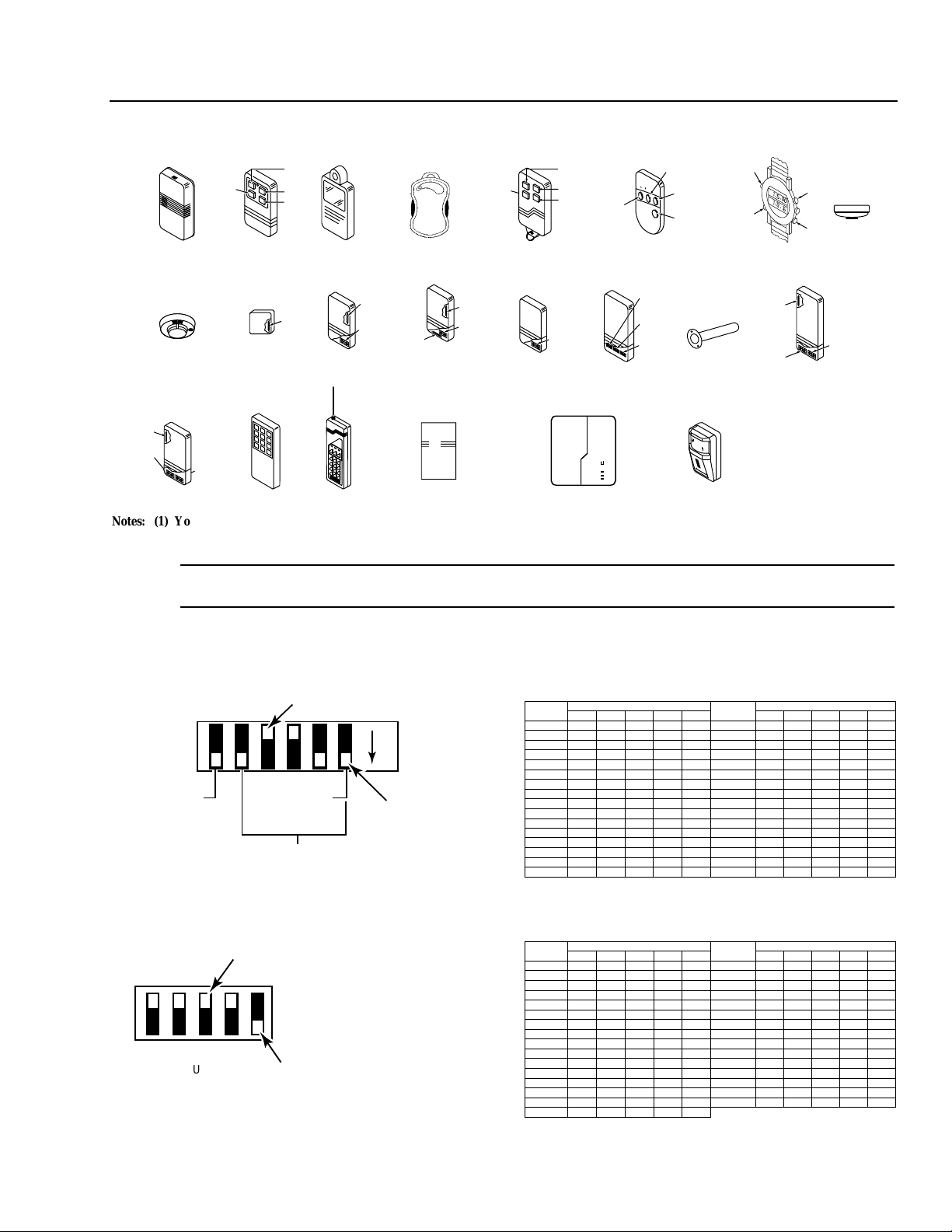
Setting DIP Switches on the 5800RL and 5827 Transmitter(s)
Set the 5800RL and 5827 Transmitters to the programmed House ID, using its DIP switches. (OFF position is indicated by ---)
Notes: (1) The 5827 transmitter can not be used in conjunction with the *58 RF Jam Detection feature.
(2) The 5800RL cannot be used in conjunction with the Auto Arm (scheduled arming) feature.
234561
SW-1 ACTIVATES
SW-6 SETS
MODE SETTING
2-6 SETS HOUSE ID
SHOWN SET FOR HOUSE ID# 12
SWITCH UP FOR "ON"
1
5
2 3 4
HOUSE ID
SHOWN SET FOR HOUSE ID# 30
SWITCH UP FOR "ON"
MODE
SWITCH DOWN
FOR "OFF"
01000-014-V1
Setting 5800RL DIP Switches
SWITCH DOWN FOR "OFF"
01000-013-VO
Setting 5827 DIP Switches
ID
0 --- --- --- --- --- 16 ON --- --- --- --1 --- --- --- --- ON 17 ON --- --- --- ON
2 --- --- --- ON --- 18 ON --- --- ON --3 --- --- --- ON ON 19 ON --- --- ON ON
4 --- --- ON --- --- 20 ON --- ON --- --5 --- --- ON --- ON 21 ON --- ON --- ON
6 --- --- ON ON --- 22 ON --- ON ON --7 --- --- ON ON ON 23 ON --- ON ON ON
8 --- ON --- --- --- 24 ON ON --- --- ---
9 --- ON --- --- ON 25 ON ON --- --- ON
10 --- ON --- ON --- 26 ON ON --- ON --11 --- ON --- ON ON 27 ON ON --- ON ON
12 --- ON ON --- --- 28 ON ON ON --- --13 --- ON ON --- ON 29 ON ON ON --- ON
14 --- ON ON ON --- 30 ON ON ON ON --15 --- ON ON ON ON 31 ON ON ON ON ON
DIP SWITCH POSITIONS DIP SWITCH POSITIONS House
2 3 4 5 6
5800RL DIP SWITCH TABLE
5827 WIRELESS KEYPAD DIP SWITCH TABLE
DIP SWITCH POSITIONS DIP SWITCH POSITIONS House
1 2 3 4 5
1 --- --- --- --- ON 17 ON --- --- --- ON
2 --- --- --- ON --- 18 ON --- --- ON --3 --- --- --- ON ON 19 ON --- --- ON ON
4 --- --- ON --- --- 20 ON --- ON --- --5 --- --- ON --- ON 21 ON --- ON --- ON
6 --- --- ON ON --- 22 ON --- ON ON --7 --- --- ON ON ON 23 ON --- ON ON ON
8 --- ON --- --- --- 24 ON ON --- --- --9 --- ON --- --- ON 25 ON ON --- --- ON
10 --- ON --- ON --- 26 ON ON --- ON --11 --- ON --- ON ON 27 ON ON --- ON ON
12 --- ON ON --- --- 28 ON ON ON --- --13 --- ON ON --- ON 29 ON ON ON --- ON
14 --- ON ON ON --- 30 ON ON ON ON --15 --- ON ON ON ON 31 ON ON ON ON ON
16 ON --- --- --- ---
House
ID
2 3 4 5 6
House
1 2 3 4 5
–13–
5809
"RF"
01009-012-V0
LOOP 1
Page 14

Mechanics of Programming
General Programming Information
Programming options are stored in nonremovable, electrical ly erasable, nonvolatile EEROM memory. You can program the
system at any time, even at the installer's premises p rior to the actual installation. Simply apply power temporarily to the
Control and then program the unit as desired. There are two programming modes:
• Data field programming (used for setting various syste m options)
• Interactive menu mode programming (used for programming zone information, programming Powerline Carrier Devices,
and for entering transmitter serial numbers)
You can also program this system remotely, using an IBM Personal Computer, a modem, and Compass Downloader for
Windows. See the Remote Programming/Control (Downloading) section.
Note:
You may find it convenient to adjust the volume setting before entering the Program Mode. This will allow you to clearly hear the
feedback announcements or system beeps in the Programming Mode, of the system’s built-in speaker. To adjust the volume, press
FUNCTION + VOLUME+ [3] or [6]. Upon exiting the Program Mode, the system will reset the volume to the default value (mid
level).
!
Entering Program Mode - Use one of the following methods:
a) Press both the [✳] and [#] keys at the same time, within 50 seconds after power is applied to the Control or from exitin g
Programming mode, OR
b) After power-up, enter the Installer Code (4 1 1 2) + 8 0 0.
Note:
If a different Installer Code is subsequently programmed, use it instead of 4112 to enter the Programming mode.
Once you have entered the Program mode, data field *20 will be displayed (this is the first data field in the system) and bo th
keypad LEDs will flash.
Programming a Data Field
1. Press [*] + Field No. (for example, *21), then make the required entry.
2. When you have completely programmed a data field, the ke ypad will “beep” three times and then automatically display
the next data field in sequence. To go to a different field, press [*] plus the desired field number.
3. If the number of dig its that you need to enter in a data field is less than the ma ximum number of digits available (eg.
phone number field), enter the desired data, then press [*
4. If you enter a nonexistent field, the keypad will display “EE”. Simply re-enter [*] plus a valid field number.
To view a data field without making changes, press [#] + Field No. Data will be displayed for that field.
To delete an entry in a field, press [*] + Field No. + [*]. (Applies only to fields
Interactive Mode Programming (*56, *80, *81, *83, *84, *85)
Press [*] + interactive mode No. (for example,
A detailed procedure (with displays of prompts) is provided in later sections of this manual.
*56 Enhanced Zone Programming Mode
*
80 Device Programming Menu Mode
*
81 Zone List Menu Mode
*83 Enhanced Sequential Mode
*84 Assign Zone Voice Descriptors Voice descriptors for each zone
*85 Record Custom Voice Descriptors Up to 5 custom voice descriptors for zones
Loading Factory Defaults
To load the factory defaults, enter the Programming mode, press
tables 1-4 at the back of this manual, or press “0” if you are not selecting a default table.
If loading a default table, any data that has already been programmed into the system will be changed according to
!
the default table selected!
*
96 resets all the subscriber account numbers and CSID in preparation for an initial download.
Exiting Program Mode
*
99 allows re-entry into the Program mode using Installer Code + 8 0 0.
*
98 inhibits re-entry into the Programming mode using the Installer Code.
Note:
After exiting program mode (or upon power-up), the system takes up to a minute to reset. To bypass the reset delay, press [#] + [0].
Certain features differ between the LYNXR/LYNXR24 and the LYNXR-EN models. Verify the specific model being
installed prior to the system programming.
(This method disabled if exit Program mode using *98.)
]
to program the next data field.
*
40–*44, *88 and *94).
*
56). The keypad will display the first of a series of prompts.
Interactive Mode Used to Program
Zone characteristics, report codes, and serial numbers
5800 Series transmitter serial numbers
Powerline Carrier Devices
Zone Lists for powerline carrier activation
*
97, then press number 1, 2, 3, or 4 to select from default
–14–
Page 15
Zone Response Type Definitions
General Information
During programming, you must assign a zone type to each zone, which defines the way in which the system responds to
faults in that zone. Zone types are defined below.
Type 00
Zone Not Used
Type 01
Entry/Exit Burglary #1
01000-017-V0
Type 02
Entry/Exit Burglary #2
01000-017-V0
Zone type 00 is used to program a zone that is not used.
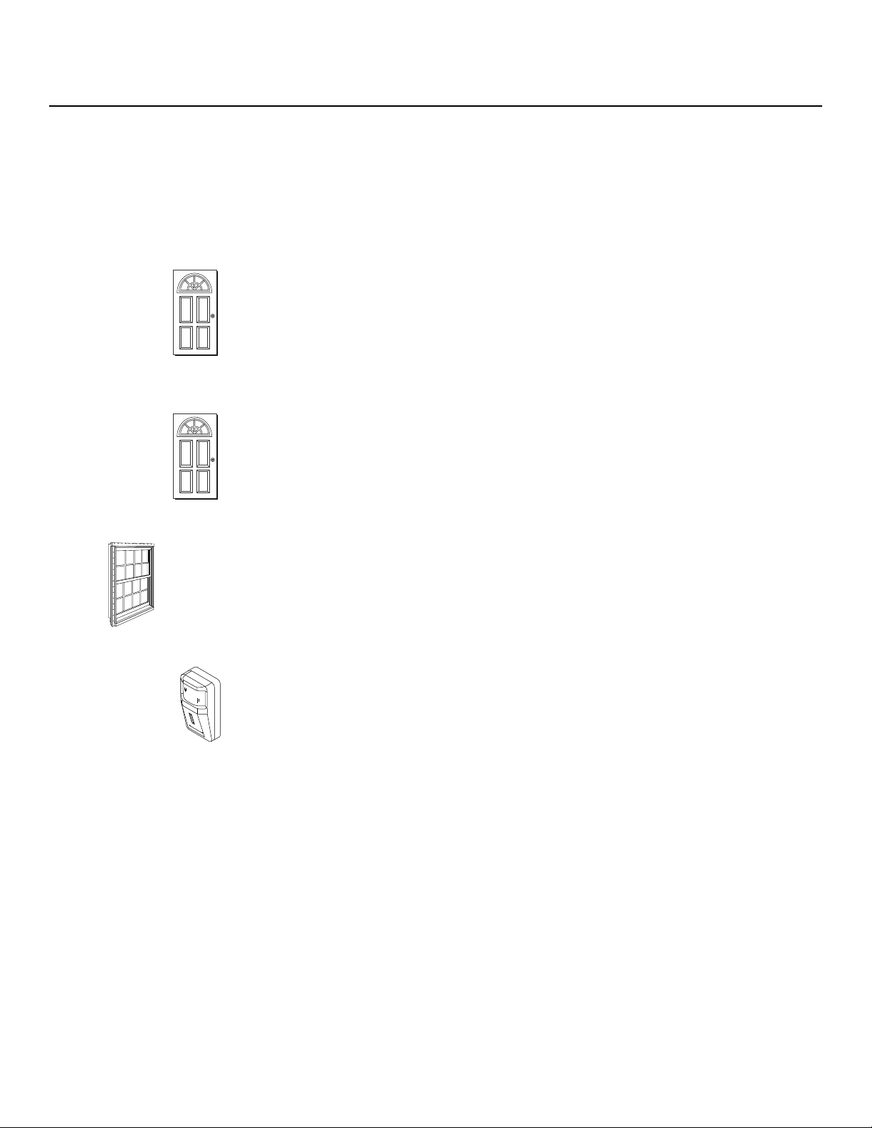
Zone type 01 is usually assigned to sensors or contacts on primary entry and exit doors.
Zone Characteristics:
Entry delay #1 is programmable from 0-99 seconds (field *35).
•
Exit delay is independently programmable from 0-99 seconds (field *34).
•
Exit and entry delays when armed in AWAY or STAY mode.
•
No entry delay when armed in INSTANT or MAXIMUM mode.
•
Exit delay regardless of the arming mode selected.
•
Zone type 02 is usually assigned to sensors or contacts on which secondary entry and exit
doors that might be further from the keypad (typically used for a garage, loading dock, or
basement door).
Zone Characteristics:
Entry delay #2 is programmable from 0-99 seconds (field *36).
•
Exit delay is independently programmable from 0-99 seconds (field *34).
•
Secondary entry delay, if armed in the AWAY or STAY mode.
•
No entry delay when armed in the STAY NO DELAY or AWAY NO DELAY mode.
•
Exit delay begins regardless of the arming mode selected.
•
Type 03
Perimeter Burglary
01000-018-V0
Type 04
Interior, Follower
5890 / 5890PI
01000-019-V1
Type 05
Trouble by Day/
Alarm by Night
Type 06
24-hour
Silent Alarm
Zone type 03 is usually assigned to all sensors or contacts on exterior doors and windows.
Zone Characteristics:
Instant alarm, when armed in AWAY, STAY, STAY NO DELAY, or AWAY NO DELAY
•
mode.
Zone type 04 is usually assigned to a zone covering an entry area (i.e.: foyer, lobby, or
hallway) that one must pass upon entry (after faulting the entry/exit zone) to reach the
keypad. It provides an instant alarm if the entry/exit zone is not violated first, and
protects an area in the event an intruder has hidden on the premises before the system is
armed, or gains access to the premises through an unprotected area.
Zone Characteristics:
Delayed alarm (using the programmed entry/exit time) if entry/exit (types 01 or 02) or
•
interior-with-delay (type 10) zone is faulted first.
Instant alarm in all other situations.
•
Active when armed in AWAY or AWAY NO DELAY mode.
•
Bypassed automatically when armed in STAY or STAY NO DELAY mode.
Zone type 05 is usually assigned to a zone, that contains foil-protected doors or windows
or covers a sensitive area (i.e.: stock room, drug supply room, etc.) It can also be used on
a sensor or contact in an area where immediate notification of an entry is desired.
Zone Characteristics:
Instant alarm, when armed in AWAY, STAY, STAY NO DELAY, or AWAY NO DELAY
•
(night) mode.
Provides a latched trouble sounding from the keypad and, if desired, a central station report
•
during the disarmed state (day).
Zone type 0 6 is usually assigned to a zone conta ining an E mergency but ton
(silent emergency).
Zone Characteristics:
Sends a report to the central station but provides no keypad display or sounding.
•
–15–
Page 16

Zone Response Type Definitions
Zone type 07 is usually assigned to a zone containing an Emergency
button (audible emergency).
Zone Characteristics:
Sends a report to the central station, and provides alarm sounds externally and
•
at the keypad.
Zone type 08 is u sually assig ned to a zone c ontaining a b utton for us e in
personal emergencies or to a zone containing monitoring devices (i.e.:
water or temperature sensors, etc.).
Zone Characteristics:
Sends a report to the central station and provides an alarm sound at the keypad.
•
(No bell output is provided and there is no keypad timeout.)
Zone type 09 can be assigned to any wireless zone used as a
fire zone. This zone type is always active and cannot be
bypassed.
Zone Characteristics
Bell output will pulse when this zone type is alarmed.
•
:
Zone type 10 is bypassed when the panel is armed in the STAY or STAY
NO DELAY mode.
Zone Characteristics
Entry delay #1 (with programmed entry time) when armed in the AWAY
•
mode.
Entry delay begins whenever sensors in this zone are violated, regardless of
•
whether an entry/exit delay zone was tripped first.
No entry delay when armed in the
•
Exit delay regardless of the arming mode selected.
•
:
AWAY NO DELAY
5806/5807/5808
01000-020-V0
Type 07
24-hour
Audible Alarm
Type 08
24-hour
Auxiliary Alarm
Type 09
Supervised
Fire
Type 10
Interior w/Delay
mode.
Type 20
Arm–Stay
Type 21
Arm–Away
Type 22
Disarm
Type 23
No Alarm Response
Type 24
Silent Burglary
Zone type 20 is a special-purpose zone type used with 5800 Series
wireless pushbutton units.
Zone Characteristics:
Exit delay regardless of the arming mode selected.
•
System is armed in the S TAY mode when the zone is activat ed.
•
Zone number is sent to the central station as a u ser number when arming or
•
disarming.
Zone type 21 is a special-purpose zone type used with 5800 Series
wireless pushbutton units.
Zone Characteristics
System is armed in the AWAY mode when the zone is activated.
•
Zone number is sent to the central station as a u ser number when arming or
•
disarming.
:
Zone type 22 is a special-purpose zone type used with 5800 series
wireless pushbutton.
Zone Characteristics
Disarms the system when the zone is activated.
•
:
Zone type 23 can be used on a zone when a Powerline Carrier Device
(e.g., X-10) action is desired, but with no accompanying alarm (e.g., front
door light).
Zone type 24 is usually assigned sensors or contacts on exterior doors and
windows where bells and/or sirens are NOT desired.
Zone Characteristics
Instant alarm, with NO audible indication when is armed in the AWAY, STAY,
•
STAY NO DELAY, or AWAY NO DELAY mode.
Report sent to the central station.
•
Note:
Keypa d beeps if the zone i s faulted when system i s disarmed and Chim e mode is
on.
:
–16–
Page 17

Data Field Descriptions
Defaults (where applicable) are Indicated in Text.
The following pages list all data fields in this Control (in numerical order). Use the blank programming form to record the
data for this installation. Note that both ke ypad LEDs flash while in Programming mode.
Note: Entry of a number other than the one specified will give unpredictable results.
*
*
*
*
*24
*
*
*
*
*
*
*
*
*
20
21
22
23
25
26
27
29
30
31
32
33
34
Installer Code
Enter 4 digits, 0-9
Quick Arm Enable
0 = do not allow quick arm
1 = allow quick arm
Keypad Backlight Timeout
0 = no timeout; always backlight keys
1 = turn backlighting off after inactivity
Forced Bypass
0 = no forced bypass
1 = provide automatic bypass of all open (faulted) zones
RF House ID Code
00 = disable all wireless keypad usage
01-31 = House ID
Powerline Carrier Device
0 = A 4 = E 8 = I # + 12 = M
1 = B 5 = F 9 = J # + 13 = N
2 = C 6 = G # + 10 = K # + 14 = O
3 = D 7 = H # + 11 = L # + 15 = P
Chime by Zone
0 = no (chimes on fault of any entry/exit or perimeter
zone when Chime mode is activated
1 = yes (chimes on fault of those zones assigned to
Zone List 3 when Chime mode on)
Real Time Clock Display
0 = do not display the time
1 = display the time
Daylight Savings Time Sta r t/End Month
0, 0 = no daylight saving time used
1-12 = start month and end month
Daylight Savings Time Start/End Week
0 = disable 4 = fourth weekend
1 = first weekend of month 5 = last weekend
2 = second weekend 6 = next to last
3 = third weekend 7 = 3
Single Alarm Sounding Per Zone
(per armed period)
0 = no limit on alarm sounding per zone
1 = limit alarm sounding to once per arming period for a
given zone
LYNXR/LYNXR24
selected in field *91
LYNXR-EN
Range Radio is connected to the Trigger Single (Neg.) terminal
#8.
Fire Sounder Timeout
0 = yes, fire sounder timeout after time programmed in
field *33
1 = no fire sounder timeout; continue sounding until
manually turned off
Alarm Bell Timeout
0 = No timeout 2 = 8 min 4 = 16 min
1 = 4 min 3 = 12 min
Exit Delay
00-99 = exit delay time in seconds
- Applies to Long Range Radio Output if “0” is
- Applies to Long Range Radio Output if a Long
(X-10)
rd
from last
House ID
The Installer Code is us ed to enter the 4-digit Master Security C o de. See
"Master Code" in the
If enabled, security code is not required to arm the system. The user
simply presses and holds down the AWAY or STAY key to arm.
This option allows the choice of either always backlighting the keypad or
turning the backlighting off after 10 seco nds of keypad inactivity.
All zones bypassed by this function will be displayed after the bypass is
initiated.
Note:
UL installations: must be 0 (no forced bypass)
The House ID identifies receivers and wireless keypads.
If a 5827/5827BD Wireless Keypad or 5804BD/580 4BDV Transmitter is
to be used, a House ID Code MUST be entered, and the keypad should be
set to the same ID.
Powerline Carrier Devices require a House ID. This field identifies this
House ID to the Control. The Powerline Carrier Devices are
programmed in field * 80.
This option allows the installer to define the specific zones intended to
chime when faulted while the s ystem is in Chime m o de. If enabled, these
zones are defined in zone list 3 (see
Refer to the User’s Manual for setting the clock time and date.
Enter # + 10 for 10, # + 11 for 11, and # + 12 for 12.
Enter the appropr iate start and end weekend of the month.
UL installations: must be 0 (no li mit)
This field applies only to burglary zones (zone response types 1-5, 10),
and affects long range radio reporting but does not affect central station
reporting.
Note:
This field applies only to the bell and does not affect keypad
sounds.
This Control complies with NFPA requirements for temporal pulse
sounding of fire notification appliances.
Temporal pulse sounding for a fire alarm consists of the following:
3 pulses – pause – 3 pulses – pause – 3 pulses. . .
This field determines whether the external sounder will shut off after time
allowed, or continue until manually turned off.
UL installations: must be set for a minimum of 4 min (option 1)
The system will wait the time entered before sounding an alarm if the exit
door is left open af ter the system has been armed.
UL installations: must be set for a maximum of 60 seconds
System Operation
section for proce dur e .
*81 Zone List Menu Mode
–17–
).
Page 18

Data Field Descriptions
*
35
*
36
*
37
*
38
*
39
DIALER PROGRAMMING (*40–*50)
Fields *40, *41, *42:
a pause
*
40
*
41
Entry Delay 01
00-99 = entry delay time in seconds.
Entry Delay 02
00-99 = entry delay time in seconds.
Audible Exit Warning/Quick Exit
Exit Warning Quick Exit
0 = no exit warning sound
1 = provide exit warning sound
when armed AWAY
Confirmation of Arming Ding
0 = no ding
1 = confirmation ding after arming system
2 = confirmation ding after arming from RF button or
RF keypad only
Power Up In Previous State
0 = always power up in a disarmed state
1 = assume the system status prior to power-down
Enter up to the number of digits shown. Do not fill unused spaces. Enter 0–9, # + 11 for ‘*’; # + 12 for ‘#’; # + 13 for
(2 seconds)
PABX Access Code
Enter up to 6 digits if PABX is needed to access an
outside line.
Primary Phone No.
Enter up to 20 digits.
0 = no quick exit
1 = allow quick
exit
*
42
Secondary Phone No.
Enter up to 24 digits.
Fields *43 and *44:
Enter [*] as the fourth digit if a 3-digit account number (for 3+1 dialer reporting format) is used. Enter 0 as the first digit of a 4-digit
account number for Nos. 0000–0999. Exit field by pressing [*] if only 3 digits are u sed. To clear entries fro m field, press *43
See blank Programming Form for examples of account number entries. If using the paging feature, do not enter a leading 0 in the
subscriber account number, and do not use digits A-F anywhere in the number. Some paging systems provide voice mail capability, which
is activated by a leading 0 in the message. Enter digits 0–9; # +11=B; # +12=C; # +13=D; # +14=E; or # +15=F.
*
43
*
44
*
47
Primary Subs Account No.
Enter four digits .
Secondary Subs Account No.
Enter four digits.
Phone System Select
Note:
For LYNXR/LYNXR24 only options 0, 1, 2, and
3 are applicable. For LYNXR-EN all options
apply.
Central
Station Pulse Tone Pulse Tone
No
WATS
WATS
0 = No
Speaker
Phone
2 = No
Speaker
Phone
1 = No
Speaker
Phone
3 = No
Speaker
Phone
Dialing Mode
4 = With
Speaker
Phone
6 = With
Speaker
Phone
5 = With
Speaker
Phone
7 = With
Speaker
Phone
The system will wait the time entered before sounding alarm upon entering
if system is not disarmed. UL installations: must be set for a maximum of 45
seconds
The system will wait the time entered before sounding alarm upon entering.
UL installations: must be set for a maximum of 45 seconds
Exit Warning: Soun d consists of slow continuous beeps until last 5 seconds,
when it chan ges to fast beeps. The warning sound will end at the
termination of exit delay.
Quick Exit: If enabled, user can restart the exit delay time after arming in
STAY mode by entering the user code and pressing the
pressing the
user disarm then re-arm the system a f ter allowing someon e to enter or exit
Confirmation of arming is provided by a 1/2 second external sounder “ding”
that sounds when closing report is s ent, or at the end of exit delay.
If Option 2 is selected the external s o under “ding” occurs immediately aft er
the system receives the RF transmission.
When the system powers up armed, an alarm will occur 1 minute after
arming if a zone is faulted, and any bypassed zones will be unbypassed.
Note: If the previous state was armed
respond to sensor changes for 1 minute, which allows time for sensors such
as PIRs to stabilize. UL installations: must be 1 (power up in previous state)
If fewer than 6 digits need to be entered, exit by pres sing [*]. To clear
entries from field, press *40*.
If fewer than 20 digits entered, exit by pressing [ *]. To clear entries from
field, press *41*.
Note:
Backup reporting (8 attempts are made to the secondary phone number if
no kissoff is received after 8 attempts to the primary number) is automatic
only if there is a secondary phone number (field *42).
If fewer than 24 digits entered, exit by pressing [ *]. To clear entries from
field, press *42*. See backup reportin g note for field *41. If using the
paging feature, enter the pager phone number here.
Enter the primary subscriber account number.
To clear entries from field, press *43*.
Enter the secondary subscriber account number.
To clear entries from field, press *44*.
This option is used to enter the correct type of phone dialing (pulse or tone),
and to select the correct WATS line option for the Central Station. For
LYNXR-EN only this option is used to activate the speaker phone option.
Note:
If using pulse dialing, you must enter the numbers slowly in ord er to
allow the pulse dialer time to operate.
key if Quick Arm is enabled. This avoids having the
STAY
or
AWAY
STAY
, the system will not
STAY
–18–
key, or by
* or *44*
.
Page 19

Data Field Descriptions
*
48
*
49
*
50
*
51
*
52
*
53
*
58
Report Format for Primary/Secondary
Primary Secondary
See choices below See choices below
0 = 3+1; 4+1 ADEMCO Low Speed Standard
1 = 3+1; 4+1 Radionics Standard
2 = 4+2 ADEMCO Low Speed Standard
3 = 4+2 Radionics Standard
6 = 4+2 ADEMCO Express
7 = ADEMCO Contact ID Reporting
8 = 3+1; 4+1 ADEMCO Low Speed Expanded
9 = 3+1; 4+1 Radionics Expanded
Split/Dual Reporting
To Primary To Secondary
0 = All reports None, unless primary
fails, then all
1 = Alarms, Restore, Cancel Others
2 = All except Open/Close, Test Open/Close, Test
3 = Alarms, Restore, Cancel All
4 = All except Open/Close, Test All
5 = All reports All
To Primary To Paging Number
6 = All reports except Open/Close Alarms, Open/Close ‡,
Troubles
7 = All reports Alarms, Troubles
8 = All reports Alarms, Open/Close ‡,
Troubles
9 = All reports except Open/Close Open/Close
‡
Will report Users 0, 5-8, and, if using wireless button-type
devices, will report the zone number of the arm or disa rm
button 26-33. All other zones and users are not reported.
15-Second Dialer Delay (Burglary)
0 = no dialer delay
1 = provide 15-second delay of burg. alarm report
Periodic Test Report
0 = no test report 2 = weekly
1 = once every 24 hrs 3 = once every 30 days
First test Report Offset
0 = 24 hrs after exit program mode or download
1 = 6 hours after exit program mode or download
2 = 12 hrs after exit program mode or download
3 = 18 hrs after exit program mode or download
Sescoa/Radionics Select
0 = Radionics (0–9, B–F reporting)
1 = SESCOA (0–9 only reporting)
RFJam Detection
0 = no jam detection
1 = RF jam detection with event logging, but no
central station report
2 = RF jam detection with event logging and with
central station report (if trouble/restore report is
enabled in fields *60, *71)
‡
Enter * as the 4th digit of *43 through *44, if 3+1 dia ler reporting is to be
used. (For an explanation of these form ats, see the System C o m munication
section of this manual.)
Notes:
(1) The maximum number of alarm and alarm restore reports during
(2) Op tion 7 (ADEMCO Contact ID Report ing) must be selected for
Use options 0 - 5 when reporting to telephone receivers.
Use options 6 - 9 when reporting to a pager is des ired.
Pager Report Format
Options 6-9 send reports to the primary phone number and send reports to a
pager, which has its phone number entered as the secondary phone number
in field *42.
The pager report is a 7-digit code, with optional 16-digit prefix, in the
following format:
AAAAAAAAAAAAAAAA-EEE–00NN
AAA = Optional 16 digits for PIN number, etc. See field *88 for full
EEE = 3-digit Event Code as follows:
00 = Always displayed before 2-digit user/zone no.
NN = 2-digit user number or zone number, depending on the type of
If enabled, provides communication delay to the central station and allows
the subscriber time to avoid a fa lse alarm transmission. Delay does n ot
apply to zone type 6, 7, 8, and 24 alarms, wh ich are always sent as soon as
they occur. UL installations: must be 0 (no delay)
Test report code entered in field *64 is sent.
This is the time to first report from programming or downloading.
Select 0 for all other formats.
For Event Logging, Opti on 2 must be selected.
If the control detects an RF jam condition, a “FAULT” message appears for
zone 90. The Contact ID code for RF Jam is 344.
Note:
one armed per iod is determined by field *92.
AVM.
where:
description of these characters.
911 = Alarm (NN = zone number)
101 = Open, system disarmed (NN = user no.)
102 = Close, system armed (NN = user no.)
811 = Trouble (NN = zone no.)
event (EEE) th at occurred. NN=00 indicates AC loss, system low
battery, or low battery in 5827/5827BD.
This feature cann ot be used in conjunction with the 5827 wireless keypad .
–19–
Page 20

Data Field Descriptions
*
SYSTEM STATUS AND RESTORE REPORT CODES PROGRAMMING (* 59 –* 76, &
Program Report Codes using the interactive *56 Enhanced Zone Programming Mode, or codes can be entered in data fields *59-*76, *89.
The following is a set of guidelines when programming report codes. The actual report code digits that you enter depend upon the
particular installation, and should be in agreement with you and the central station office receiving the si gnals.
With a 3+1 or 4+1 S tandar d For mat:
receivers), "#+11" for B, "#+1 2" for C, "#+13" for D, "#+14" for E, "#+15" for F. Entering "0" in the first box will disable a report.
Entering "0" in the second box results in automatic advance to the next field.
With an Expanded or 4+2 Format:
the first box will disable a report. Entering "0" in the second box will eliminate the expanded message for that report.
With ADEMCO Contact ID® Reporting:
until you have used up available digits. If the number of zones exceeds the number of avail able digits, begin with digit 1 again. This is an
"enabling" code only and is not the actual code sent to the central station office. Entries in the second boxes will be ignored. For system
status (non-alarm) codes, enter a “1” in the first box for all the system conditions you want to send to the central station. A "0" in the first
box disables the report.
SYSTEM STATUS REPORT CODES
*
59
Exit Error Report Code
See notes above
*60
*61
*62
*
63
*
64
*
65
*
66
*
67
*
68
Trouble Report Code
Bypass Report Code
AC Loss Report Code
Low Battery Report Code
Test Report Code
Open Report Code
Arm AWAY/STAY Report Code
above
)
RF transmitter Low Batt. Report Code
notes above
Cancel Report Code
)
Enter a code in the first box: 1–9, A, B, C, D, E, or F. Enter "#+10" for A (reports a “0” on some
Enter codes in
Enter a digit in the first box to enable the zone to report. Use a different digit for each zone
*
(
59–*68)
(See notes above
(See notes above
(See notes above
(See notes above
(See notes above
(See notes above
(See notes above
boxes (1st and 2nd digits) for 1–9, or A–F, as described above. Entering "0" in
both
If the system is armed and an entry/exit or interior zone is still open
after the exit delay time has expired, an alarm will sound at the
keypad and external sounder. If the system is disarmed before the
end of the entry delay that immediatel y f ollows, the alar m s ounding
will stop and no message will be sent to the central station. The
keypad will display “CA (CANCELED A LARM).”
If the system is not disar med before the end of the entry delay
mentioned above, and an entry/exit or interior zone is still open, an
“exit alarm” message will be sent to the central station if an Exit
Error report code is selected in this field. The keypad will display
“EA (EXIT ALARM),” and the alarm sounding will continue until
the system is disarmed (or timeout occurs).
An Exit Alarm condition will also result if a fault occurs in an exit or
interior zone within 2 minutes following the end of the exit delay,
and an “Exit Alarm” message will be sent to the central station.
If Contact ID format has been programmed, the message will contain
the zone number and error code 374 (Trouble–Exit Error). If 4+2
format is used, the digit entered in this field will be sent followed by
the second digit of the programmed alarm code for that zone. If 3+1
or 4+1 format is used, only the digit entered in this field will be sent.
This message wi ll go to the pri mary phone no. Under any of these
conditions, no restore message will be sent.
If “0” is entered in this field, no special message will be sent, only
the regular alarm and alarm restore code for the zone.
)
)
)
)
)
)
(See notes
(See
)
This will be sent if a zone goes into trouble.
This will be sent when a zone is manually bypassed.
Timing of this report is random with up to a 4-hour delay. If AC
restores before the report goes out, there is no AC restore r ep ort.
This will be sent when a low battery condition exists in the system’s
standby battery.
This is sent periodically to test that the communicator and phone
lines are operational (frequency of report is selected in field *51).
This is sent upon disarming of the system. 2nd di git = user number, if
expanded or 4+2 reporting is selected.
This option allows for independent programming of AWAY and
STAY reports. 2nd di git of report is user number if expanded or 4+2
reporting is selected.
NOTE: OPEN reports are not sent if the associated closing report is
not enabled.
This is sent in the event that a wireless transmitter low battery
condition exists.
This is sent upon disarming of the system after an a larm condition
was reported.
89)
–20–
Page 21

RESTORE REPORT CODES (*70–*76)
*
70
*
71
*
72
*
73
*
74
*
75
*
76
*
87
*
88
Alarm Restore Report Code, 1st Digit
(See notes above
Trouble Restore Report Code
(See notes above
Bypass Restore Report Code
(See notes above
AC Restore Report Code
Low Battery Restore Report Code
(See notes above
RF Transmitter Low Batt. Restore Code
(See notes above
Test Restore Report Code
AUX Function/1-Button Paging
0 = Aux key performs defined function (macro)
1 = Aux key sends predefined message to pager
Pager Characters
Enter up to 16 digits that will appear in front of the 7digit pager message.
Enter [#] + [11] for “* ”
Enter [#] + [12] for “# ”
Enter [#] + [13] for 2-second pause
NOTES: Verify that the pager supports [*] and [#]
characters before using them. Some pagers
require an addition al delay [pause] in order to
receive the entire mess ag e.
)
)
)
(See notes above
)
)
(See notes above
*
89
*
90
Event Log 80% Full Report Code
(See notes above
Event Logging Options
0 = No event logging
1 = log Alarm/Alarm Restore
2 = log Trouble/Trouble Restore
4 = log Bypass/Bypass Restore
8 = log Open/Close
x = log combination of events (add value of entries)
)
Data Field Descriptions
)
)
Sent when the zone that caused an alarm is restored to its non-faulted
condition. 2nd digit is automatically sent as the 2nd digit of the zone alarm
report code programmed in field *56, if expanded or 4+2 reporting is
selected.
Sent when a trouble in a zone is restored.
Sent when a zone that has been bypassed is unbypassed.
Sent when AC power has been restored after an AC power outage.
Sent when a system low battery condition is restored to normal.
Sent when a transmitter that previously sent in a “low battery” message
has sent a message indicating it no longer has a low battery condition.
Sent when the test mode is exited. A restore code entered here will cause a
restore message to be sent when Test mode is exited.
If “0” is entered, user can define a macro function for the AUX key. See
user manual for description of the use of this key.
If “1” is entered, you must also select an option 6-9 in field *49. The
actual pager message is 999-9999. Note that the hyphen may not be
displayed, depending on the pager service.
A macro cannot be run from the Test mode.
Note:
If entered, these digits will appear in front of the 7-digit pager message
sent by the control (either upon a syst em event or upon pres sing the AUX
key [if programmed for paging]), and during latch key report (if enabled
during scheduling). These digits can consist of a PIN number, account
number, pauses or special digits needed by the pager (these types of
characters are not displayed), or any other characters the user chooses that
will be displayed (eg., using a character code to distinguish between
control panel messages and other pager messages).
You do not need to fill all 16 digits. Press [*] + next field number to exit
the field. To clear the field, press *88*.
See field *87 to select the AUX key Paging feature. See field *49, which
must have an option 6-9 selected to enable paging messages, for
description of the pager message.
If an Event Logging selection is made in field *90, a message can be sent
to the central station receiver when the log is 80% full. If the log becomes
full, a new message will overwrite the oldest message in the log.
All control and read out from the log, aside from the selection ma de
Note:
by the installer in field *90, is accomplished via the downloader.
Example: To select “Alarm/Alarm Restore” and “Open/Close,” enter 9 (1
+ 8); to select all events, enter #15.
Default “3” = alarm/alarm restore (1) plus trou ble/trouble restore (2).
The system has the ability to record various events in a history log (84event capacity). The types of events to be logged can be selected as
indicated. At any time, the downloader operator can then upload the log
and view or print out all or selected cat egories of the log. The log can also
be cleared by the download operator.
The display/printout at the central station will show the date, time, even t,
and description of the occurrences.
Note:
System messages are logged when any non-zero selection is made.
–21–
Page 22

Data Field Descriptions
The features programmed in Field *91 differ between LYNXR models. Ensure you use the correct option
!
for the model you are installing!
*
91
LYNXR/LYNXR24
Long Range Radio/Alarm Audio Verification
Trigger/Remote Phone Control
0 = long range radio trigger only
1 = AVM and remote phone control
2 = long range radio trigger and remote phone control
4 = AVM only
Notes: For UL installations alarm audio verification
cannot be used. Alarm audio ver ifi ca tio n will o nl y
function when Contact ID is selected.
LYNXR-EN
Alarm Audio Verification/Remote Phone
Control
0 = none
1 = AVM and remote phone control
2 = remote phone control only
4 = AVM only
Notes: (1) For UL installations alarm audio verification can
(2) AVM/ Remote phone can only be used if the
not be used. Alarm audi o ver if ica ti o n will on ly
function when Contact ID is selected.
remote phone sup ports DTMF commands.
*
92
*
93
Number of Reports In Armed Period
0 = reports limited to a total of 10
1 = unlimited number of reports
Flexible Callback
0 = no flexible callback
1 = last digit flexible
2 = last 2 digits flexible
3 = last 3 digits flexible
DOWNLOAD INFORMATION (*94, *95)
*
94
*
95
Download Call Back Phone Number
Enter up to 20 digits as follows: 0–9, # +11 for “*”, # +
12 for “#”, # + 13 for a pause.
Ring Detection Count For Downloading/
Remote Phone Access
0 = disable station initiated download and remote phone
1-14 = number of rings before control picks up phone
line
15 = defeat answering machine
The remote Phone Access feature applies only to the
Note:
LYNXR-EN model.
For LYNXR/LYNXR24, this option is used to enable the Long Ran ge
Radio or Alarm audio Veri fication or remote pPhone control options. If
long range radi o (0 ) is selected, trigger output (terminal sc rew # 8) will
generate a steady signal for burglary alarm (single 3 to 4-second pulse for
all types of silent alarms) or a temporal signal for fire alarm. (Refer to
Long Range Radio Installation Instructions for appropriate wiring.) Alarm
audio verification requires the in stallation of the LYNX-AVM
Notes:
(1) If long range radio is being connected alarm audio verification
(2) In order to activate the remote phone access feature and defeat an
(3) Remote phone session will be terminated if a report must be sent.
(4) If
(5) Alarm audio verification will only function when Contact ID is
(6) If an alarm will be reported to primary and secondary phone
(7) If an alarm will be reported to a pager (6, 7, or 8 in field *49),
For LYNXR-EN this option is used to enab le the two-way voice an d/or the
remote phone control features.
Notes:
(2) In order to activate the remote phone access feature and defeat an
(3) Remote phone session will be terminated if a report must be sent.
(4) Alarm audio verification will only function when Contact ID is
(5) If an alarm will be reported to primary and secondary phone
(6) If an alarm will be reported to a pager (6, 7, or 8 in field *49),
This option can be used to limit the number of mess ages (alarm & alarm
restore reports) sent to the central station in an armed period.
UL installations: must be 1 (unlimited reports)
If enabled, the control will ignore the last 1, 2, or 3 digits of the
programmed callback number (field *94) during a single download session.
This allows the download operator to temporarily change the callback phone
number by the number of digits selected, which allows the control to call
back similar, but different numbers during a single session. For example, if
downloading to a large number of controls, the operator can command the
controls to call back phone numbers 555-1111, 555-1112, 555-1113, etc.,
thus spreading the communications among severa l computers.
This is the phone number the control will use to call back the downloadin g
computer.
Do not fill unused spaces. End field by pressing *. To c lear entries from
field, press *94*.
The Remote Phone Access feature applies only to the LYNXR-EN model.
Enter “15” to select defeat answering machine mode. If an answering
machine is on the premises, you need to dial the premises and hang up on
the first ring. Wait at least five (5) seconds (but no more than 22 seconds)
and dial the premises phone number again. LYNXR-EN will pick up and
announce “SYSTE M” every three seconds.
Note:
cannot be used.
answering m a chine ensure t hat the correct ri ng detection count
(“15”) has been programmed i n f ield *95.
alarm audio
alarm trigger is not available, and the long range radio can not be
connected.
selected and cannot be used for UL installations.
numbers, AVM can only be via the secondary number.
AVM cannot be used.
(1) No programming is required if connecting an ALARMNET 784 5C
device because the option is always enabled.
answering m a chine ensure t hat the correct ri ng detection count
(“15”) has been programmed i n f ield *95.
selected and cannot be used for UL installations.
numbers, AVM can only be via the secondary number.
AVM cannot be used.
To enter a number higher than 9 you must first press the [#] key.
verification mode is selected, the long range radio
–22–
Page 23

Data Field Descriptions
Other Programming Commands
*
56 ENHANCED ZONE PROGRAMMING MODE
Interactive menu mode used for programming zone attributes and report codes. Refer to the
section for procedure.
*
80 DEVICE PROGRAMMING MENU MODE
Mode
Interactive menu mode for programming Powerline Carrier Devices. Refer to the *80 Device Programming Menu Mode
*
81 ZONE LISTS FOR OUTPUT DEVICES
*
83 ENHANCED SEQUEN TIAL MODE
section for detailed procedure.
Interactive menu mode for programming zone lists for Powerline Carrier Devices. Refer to the *81 Zone List Menu Mode
section for detailed procedure.
Interactive menu mode used to enter RF transmitter serial numbers. Refer to the *83 Enhanced Sequential Mode section for
detailed procedure.
*84 ASSIGN ZONE VOICE DESCRIPTORS
Interactive menu mode used to assign descriptors to each zone. These descriptors will be announced whenever the system
announces an event involving a zone.
*85 RECORD CUSTOM VOICE DESCRIPTORS
Interactive menu mode us ed to record custom descriptors for use with each zone.
*
96 INITIALIZE DOWNLOAD ID AND SUBSCRIBER ACCT. NO. FOR DOWNLOADING
Pressing *96 initializes the system for downloading.
*
97 SET ALL PROGRAM FIELDS TO 1 OF 4 SETS OF DEFAULT VALUES
See Default Tables at the end of this manual.
*
98 EXITS PROGRAMMING MODE
Prevents re-entry by: Installer Code + 8 + 0 + 0; allows re-entry only by Power-up, then [*] and [#].
*
99 EXITS PROGRAMMING MODE
Allows re-entry to program mode by: Installer Code + 8 + 0 + 0; or by Power-up, then [*] and [#].
*56 Enhanced Zone Programming
–23–
Page 24

*56 Enhanced Zone Programming Mode
This is an interactive menu mode that is used to program zone numbers, zone types, alarm and report codes, and to identify
the type of loop input device. This mode can also be used for entering 5800 Series transmitter serial numbers.
Note: There are two methods for entering transmitter serial numbers. The first method is by using *56 Enhanced Zone
You must refer to these instructions or to the Program Form while programming the system because the keypad display does
not show prompt titles. Instead, prompts are indicated by a number/letter combination.
The prompts for *56 are as follows:
Programming mode (described below). The second method is by using *83 Enhanced Sequential Mode. Note that the
*83 Enhanced Sequential Mode requires that all zone information first be entered using *56 Enhanced Zone
Programming mode.
A 01 Zone Number --------------------------for entering the zone number
b Zone Type ------------------------------for entering zone type
C Report Code----------------------------for entering the zone’s r eport co de
d Input Type ------------------------------for entering the transmitter’s input type
E Loop Number --------------------------for entering the transmitter loop number
F Delete Serial Number? ---------------for deleting existing serial number
1A Enroll Mo de?---------------------------selects ser ial number enroll mode
1b Serial Numb er--------------------------for entering transmitter’s serial number
1C Voice Descriptor? ---------------------se lects voice descript or mode
1d Descriptor 1 ----------------------------for entering fir s t descript or word
1E Descriptor 2 ----------------------------for entering second descr iptor word
1F Descripto r 3 ----------------------------for entering thi rd descriptor word
–24–
Page 25

*56 Enhanced Zone Programming Mode
While in Program mode, press
Refer to the zone assignment table for
The following explains the *56 p rompts in detail. The left two columns identi fy the prompts and list the avai lable entries for
each. The right-most column provides a further explanation of the entries.
Notes: (1)
% -
'
d
You may find it convenient to adjust the volume setting before entering the Programming Mode. This will
allow you to clearly hear feedback announcements or syste m beeps.
Zone number
01-41, 95, 96, 99 = Zone number
[*] = continue
00 = exit Zone Programming mode
Zone type
b
zt
00-24 = zone type
[*] = continue
[#] = return to previous prompt
Note: If 00 is accept ed as a zone type, save the 00
Report code
rc
Enter the report code for this zone.
[*] = continue
[#] = return to previous prompt
Input type
i
3 = RF (supervised RF) – sends periodic check-
in signals, faults, restore and low battery
signals
Note: RF type transmitters must remain within
4 = UR (unsupervised RF) – sends same as
“RF” type, but control does not supervise
the check-in signals
5 = BR (button type) – sends only fault and low
battery signals; does not send restores or
check-in signals
Note UR and BR type transmitters may be carried
[*] = continue
[#] = return to previous prompt
Loop number or Loop and Serial
)
l
1-4 = loop number for the zone of the
0 + [*] = continue to DELETE ZONE
[*] = continue to the ENROLL MODE prompt
[#] = return to previous prompt
number (if using RF Lear ni n g)
*
56 to enter Zone Programming Menu Mode.
*
56 on the separate programming form.
zone type and advance to th e co nfirm delete
prompt (F).
range of the receiver, ot herwise a
supervision failure signal will occur.
off premises (out of ran g e with o ut c au sin g a
supervision failure.
transmitter being entered.
PARAMETERS CONFIRMATION
prompt (F)
(1A) if not entered, or VOICE
DESCRIPTOR prompt if already entered
Enter the 2-digit zone number to be programmed and the Voice Descriptor
for the selected zone number will be announced, if it is programmed. Press
[*] to advance.
Zone 01 = hardwire
•
Zones 02-25 = RF zones (only)
•
Zones 26-41 = Button zones (only)
•
Zone 92 = Duress
•
Zones 95, 96, 99 = Panic zones
•
Pressing 00 exits mode, upon which the prompt “56” blinks, indicating the
mode is inactive. Press [*] + an y fi eld number to go to that field.
Each zone must be assigned to a zone type, which defines the way in
which the system responds to faults in that zone. Enter the 2-digit zone
type for this zone as follows:
00 = Not Used 08 = 24 Hr Aux
01 = Entry/Exit #1 09 = Fire without verify
02 = Entry/Exit #2 10 = Interior w/Delay
03 = Perimeter 20 = Arm–Stay
04 = Interior Follower 21 = Arm–Away
05 = Trouble Day/Alarm Night 22 = Disarm
06 = 24 Hr Silent 23 = No Alarm Response
07 = 24 Hr Audible 24 = Silent Burglary
The report code consists of 2 hexadecimal digits, each in turn consisting of
2 numerical digits. For example, for a report code of "3C", enter [0][3] for
"3" and [1][2] for "C".
If this is Zone 1, 95, 96 or 99, the system skips to the VOICE
DESCRIPTOR prompt (1C).
Enter the input type for the transmitter assigned to this zone. Refer to the
transmitter’s instructions for input types of each transmitter.
Note:
Zones 2-25 should be assigned Input Type 3 or 4 . Zones 26-41
should be assigned Input Type 5 only.
This prompt can be used to enroll loop number and serial number via
RF transmission or the loop number can be enrolled manually. If
using the RF Learning Mode, there is no need to manually enter a
loop number. Proceed directly to RF Learning
Note:
BR type devices cannot be enrolled by using UR or RF type. Likewise,
UR or RF type devices cannot be en rolled by using a BR type device.
There is a 52-second time-out for RF enrolling. At the end of the timeout, the system returns to the INPUT TYPE prompt (d). If enrolled, loop
number and “L” are displayed.
RF Learning
seconds apart will be required for BR type devices (device type 5). Two
beeps will sound after the second transmission, confirming that the loop
number and serial number have been learned.
- Two (2) transmissions (2 key depressions) at least 5
–25–
Page 26

*56 Enhanced Zone Programming Mode
*
-%0'
Delete zone parameters confirmation
0 = discard the delete request
1 = confirm requested delete
If 00 was entered as a zone type in p r om pt
Note:
(b), 00 will be retained and system will
advance to prompt (1C )
Enroll mode
0 = advance to the VOICE DESCRIPTOR
prompt (1C).
Note: This will save all zone p aram et ers.
1 = enter now and proceed to SERIAL
NUMBER prompt (1b).
Note: Not applicable if the serial number is
already present.
2 = copy the last serial number entered into
local ram.
Note: If this is the 1st zone, none will be in the
buffer and the panel will emit a long tone.
Not valid if serial number is alr ea d y pr es en t.
3 = view existing serial number.
Note: Only if “L” is displayed. If “L” is not
displayed, panel will emit a long beep.
9 = advance to F; delete existing serial number.
Note: Only if “L” is displayed. If “L” is not
displayed, panel will emit a long beep.
[*] = advance to the VOICE DESCRIPTOR
prompt (1C). This will save all zone
parameters.
[#] = return to the LOOP NUMBER prompt (E).
Note: In order for all e ntered parameters to be
accepted, you must advance to the VOICE
DESCRIPTOR prompt (1C).
For all other device types, four (4) transmissions are required (fault,
restore and fault, restore). A single beep will sound after the second
transmission confirming that the loop and serial number have been
captured. Following the fourth transmission the system will confirm that
the loop number and serial number have been learned and announce the
Voice Descriptor for the zone, if it is programmed, followed by two
beeps.
Press [*] to continue.
Manual Entry
(see the transmitter’s Installation Instructions for specific loop
designations).
Note:
The loop numb er can be changed even if the zone has already been
“L” indicates that the zone’s serial number has already been enrolled.
This function deletes either the serial number or all zone information that
is programmed for the zone.
If “00” was entered in the zone type, the confirmation of the delete
request will delete all information associated with the zone currently
being program m e d.
If “0” was entered in the loop numb er, the confirmati on of the delete
request will delete the serial number of to the zone currently being
programmed.
If “L” is displayed, the serial number for this transmitter has already been
entered. It may, however, still be viewed, confirmed (only if in listen
mode), or deleted.
View serial number
Enter “3”. Ea ch digit will be redisplayed, and the keypad will beep once
for digits 1-6, and three times for the last digit.
Confirm serial number
The serial number/loop number combination can be confirmed after one
transmission from a BR type device or two transmissions (fault and
restore) from a UR or RF type device. If a transmission is received that
matches the serial number and loop number entered, the s ystem will
confirm the rec eption by announci ng the Voice Descriptor for the zone, if
it is programmed, followed by three beeps, and a “C” will appear on the
display indicating the received serial number and loop number have been
confirmed. No further transmissions will be received.
Delete serial number
The serial number can be deleted by entering “9”.
If “L” is not displayed, the serial number for this transmitter has not been
previously ent ered. You may enter the s erial number manua lly, copy the
previous serial number, return t o Prompt (E) or en ter the serial number
later using the *83 Enhanced Sequential Mode.
- Enter the desired loop number and press [*] to continue
entered. Care should be taken when using this feature as it has the
capability to make zones inoperable by creating a mismatch of a
working serial number/loop number combination. This should be reconfirmed if the loop number is changed.
–26–
Page 27

*56 Enhanced Zone Programming Mode
b
-
-'
d
-
-)
-*
vi
vi
vi
Serial number
Enter the transmitter’s 7-digit serial number.
[#] = return to prompt 1A and reject any serial
numbers entries that have been made.
[*] = return to prompt 1A, (if a valid serial
number has been entered, the "
displayed and the serial number will be
copied into EEROM from the last serial
entered into the buffer.)
Note: Thi s pr ompt can be used onl y to manu ally
enroll a serial number. RF enrollment will be
rejected and the current zone descriptor will
be announced, followed by a single long
beep and the system will ret ur n to pr om p t
(1A).
Voice descriptor
0 = skip to next zone (A)
1 = enter descriptor mode; existing descriptor
for this zone will be announced
Descriptor 1
Enter [#] + 2-digit vocabulary index number† of
first descriptor word for this zone.
6 = accept word and advance to descriptor 2
(descriptor 2 will be announced)
8 = accept word and advance to next zone
(prompt A) – entire zone descriptor will be
announced
Press any other key to repeat the selected word.
Descriptor 2
Enter [#] + 2-digit vocabulary index number† of
second descriptor word for this zone.
6 = accept word and advance to descriptor 3
(descriptor 3 will be announced)
8 = accept word and advance to next zone
(prompt A) – entire zone descriptor will be
announced
Press any other key to repeat the selected word.
Descriptor 3
Enter [#] + 2-digit vocabulary index number† of
third descriptor word for this zone.
6 or 8 = accept word and advance to next zone
Press any other key to repeat the selected word.
(prompt A) – entire zone descriptor will
be announced
L
" is
Manual entry
Enter "1" to advanc e to Serial number prompt (1b).
Copy the previous serial number
Enter “2” to copy the previous serial number entered.
Return to Prompt (E)
Enter “#” to return to Loop Number prompt (E).
Enter transmitter later
Enter “0” or “*” if you wish to enter the transmitter later, using the *83
Enhanced Seque n ti al Mode described late r in this manual.
Notes:
(1) The panel will listen only when it is in the idle loop waiting for key
entry and a serial number has been entered. If a key is entered, the
(2 ) A long beep indicates illegal entry or duplicate seri al number/loop
In this mode, the transmitter serial numbers can only be entered manually.
Enter the 7-digit serial number printed on the transmitter. If an incorrect
digit is entered, press the [#] key to backup to prompt (1A) and start over.
When all 7 digits are entered, press the [*] key.
If 52 seconds passes and no entry has been made, the system returns to
prompt (1A).
Notes:
(2) If less than 7 digits have been entered, the keypad will emit a single
(3) If more than 7 digits have been entered, the first 6 digits will be
Each zone can have a voice descriptor of up to 3 words that will be
announced wheneve r the system announces status for that zone.
† see
Use the [6] or [8] key to advance as described.
To change the entered index number before pressing [6] or [8], simply press
[#] + desired 2-digit vocabulary index number.
If descriptor 1 is not desired, enter [#] + 99 (blank), then press [8] to return
to zone number prompt.
† see
Use the [6] or [8] key to advance as described.
To change the entered index number before pressing [6] or [8], simply press
[#] + desired 2-digit vocabulary index number.
If descriptor 2 is not desired, enter [#] + 99 (blank), then press [8] to return
to zone number prompt.
† see
Use the [6] or [8] key to advance as described.
To change the entered index number before pressing [6] or [8], simply press
[#] + desired 2-digit vocabulary index number.
If descriptor 3 is not desired, enter [#] + 99 (blank), then press [8] to return
to zone number prompt.
function must be completed and the panel will listen again.
entry
(1) If the serial and loop number combination is already present the
keypad will emit a single long beep and the system will return to the
(1A) prompt and “L” will be displayed.
long beep and return to the (1A) prompt without displaying the “L”.
saved along with the last di git that was enter ed (ent erin g 123456 789
yields the serial number 1234569).
*84 Assign Zone Voice Descriptors
*84 Assign Zone Voice Descriptors
*84 Assign Zone Voice Descriptors
section for vocabulary index
section for vocabulary index
section for vocabulary index
–27–
Page 28

*80 Device Programming Menu Mode
Powerline Carrier devices (eg., X-10 brand devices) are programmable switches that can be used to perform many different
functions. They can be used to turn lights on and off, control sounders, or for status indications. In this system, each device
must be programmed as to how to act (ACTION), when to activate (START), and when to deactivate (STOP). Each of these
is described below.
The control supports a total of 8 output devices.
The 1332X10 transformer sends signals from the control panel through the premises AC wiring to the Powerline Carrier
Devices (which ar e plugged into AC outlets). De vices plug ged into P owerline Carr ier Devices c an then b e made to perform
various functions in re sponse to commands entered at the keypads in the securit y system.
Programming Options Defined
The following will help you understand the programming of output devices when using *80 and *81 modes.
ACTION The "ACTION" of the device is how the device will respond when it is activated by the "START"
START T he "START" programming determines when and under what conditions the device will be activated. The
Start by Event
Powerline Carrier Devices are not UL Listed for fire or burglary functions a nd are intended
8
/
for home automation.
programming. There are four different choices of actions:
• ACTIVATE for 2 SECONDS and then reset.
• ACTIVATE and REMAIN ACTIVATED until stopped by some other event.
• PULSE ON and OFF until stopped by some other event.
• NOT USED when the device is not used.
following START options are available:
1. Event is the condition (alarm, fault, trouble) that must occur to a zone or group o f zones (zone list) in
order to activate the device. These conditions app ly only when a zone list is used. The different choices
for "EVENT" are listed below and in the “Programming Powerline Carrier Devices” paragraph that
follows.
• ALARM Device activates upon any alarm in an assigned zone in the zone list.
• FAULT Device activates upon any opening or short in an assigned zone in the zone list.
• TROUBLE Device activates upon any trouble condition i n an assigned zone in the zone list.
• NOT USED Device action is not dependent upon one of the above events.
2.A zone list is a gro up of zones to which the “EVENT” applies in order to activate a particular device.
Note that there are a total of 3 output device-related zone lists that can be programmed in *81 menu
mode; when the selected EVENT (alarm, fault or trouble) occurs in any zone in the selected “Start”
ZONE LIST (1, 2, or 3), activation of the selected device will START.
Start by Zone Type or System Operation
If a system operation, such as “DISARMING” or “ANY FIRE ALARM,” is to activate the device, the
appropriate choice would also be entered under the “ZONE TYPE” option. “ZONE TYPE” is used
independently of the “EVENT/ZONE LIST” combination.
If a "ZONE TYP E" is chosen, any zone of that response type going into alarm, trouble, or fault will cause
the device to activate as selected in "ACTION.” If the same “ZONE TYP E” is also chosen for the STOP
programming, any zone of that type that restores will de-activate the device.
If a "SYSTEM OP ERATION" is chosen (e.g., End of Exit Time), that operation will cause the device to
activate as selected in "ACTION.” The different choices for "ZONE TYPE" and "SYSTEM
OPERATION" are listed in the “Start zone type” paragraphs later in this sectio n, and in the Programming
Form.
–28–
Page 29

*80 Device Programming Menu Mode
STOP
During normal system operation, any devices may be manually started b y keypad entry of: Code* + [ #] + 4 + “n;” or
manually stopped by keypad entry of: Code* + [#] + 7 + “n,” where “n” = the device number to be controlled.
* Code is required for devices 7 and 8. For devices 1-6, code is not required. See User Manual for more information.
Programming Powerline Carrier Devices
While in program mode, press *80 to enter Output Device Menu Mode. This mode is used to program all output devices
used in the system. Refer to the output device table for
devices.
Note: The House ID of the Powerline Carrier Devices must be entered in data field *25.
The prompts for *80 are as follows:
80 Powerline Carrier Device Programming Main Menu prompt
A 01 De vice Numbe r ------------------------for entering the device number
b De vice Action-------------------------- for defining the action the device will perform when active
C Start Event Typ e----------------------- for assigning the event type to start t h e action
d Start Zone List -------------------------for assigning the zone list to start the action
E Start Zone Type ----------------------- for assigni ng the zone type to start the action
F Stop Zone List -------------------------for assi gning the zone list to stop the action
1A Stop Zone Type------------------------ for assigning the zone type to stop the action
The "STOP" programming determines when and under what conditions the device will be de-activated. The
following options are available:
Upon Restore of a Zone List
Restore Zone List: If a "ZONE LIST" is used as the “Stop” event, the device will de-activate when all the
zones in that list restore from a previous fault, trouble, or alarm condition. This will occur regardless of
what is programmed to "START" the device; therefore, a "RESTORE ZONE LIST" would normally only
be used when a "ZONE LIST" is used to start the device.
Upon a Zone Type or System Operation
Zone Type/System Operation: Instead of using a "RESTORE ZONE LIST," a specific zone (response) type
or system operation action can be selected to de-activate the device.
If a specific "ZONE TYPE" is chosen, a ny zone of that response type that restores from a previous alarm,
trouble, or fault condition will cause the device to de-activate.
If a "SYSTEM OPERATION" is chosen, that operation will cause the device to de-activate.
*
80 on the separate programming form when programming output
–29–
Page 30

*80 Device Programming Menu Mode
The following explains these prompts in detail. The left two columns identify the prompts and list the available entries. The
right-most column provides a further explanation of the entries.
Note: Entry of a number ot her than one specified will give unpredictable results.
% -
b
'
d
)
*
-%
aa
et
zl
zt
zl
zt
Powerline Carrier Device programming
0 = exit mode
1 = enter mode
Device number
01-08 = device number to be programmed
[*] = continue
00 = exit Device Programming mode
Device action
0 = No response
1 = Close for 2 seconds
2 = Close and Stay Closed
3 = Continuous Pulse on & off (1 sec ON, 1 sec
OFF)
[*] = continue
[#] = return to previous prompt
Start event type
0 = Not used 3 = Trouble
1 = Alarm [*] = continue
2 = Fault [#] = return to previous
prompt
Start zone list
1-3 = zone list number (to be programmed in
field *81)
0 = zone list not used for this device
[*] = continue
[#] = return to previous prompt
Start zone type
01-58 = zone type to start this device action
(select only those that are applicable)
00 = zone type not used for this device
[*] = continue
[#] = return to previous prompt
Stop zone list
1-3 = zone list to stop this device action
0 = zone list not used
[*] = continue
[#] = return to previous prompt
Stop zone type
01-58 = zone type to start this device action
(select only those that are applicable)
00 = zone type not used for this device
[*] = continue
[#] = return to previous prompt
Entering “1” advances to the next prompt below.
Entering “0” exits mode, upon which this prompt blinks, indicating the
mode is inactive.
Enter device numbers as 2-digit entries.
Enter the 1-digit action (0-3) for the device bei ng programmed (current
action is displayed).
NOTES:
1. If “3” is entered (pulse), only up to 3 different devices can be
pulsed if one of the devices is a siren/horn (X-10 Powerhouse
Security model SH10A). In addition, the siren/horn cannot be
manually acti vated using the lights on/lights off keypa d commands.
2. If using an X-10 Powerhouse Security SH10A siren:
• you must use device action “3.”
• you must change the device action default to “3” if using default
table 2 or 4
Enter the 1-digit event type (0-3) to activate the d evice being
programmed. A zone list must be used in conjunction with an event. If a
zone type/system operation is to be used instead of an event, enter “0”.
If a zone list will be used to start the device action, enter the zone list
number at this prompt.
If a zone type or system operation will be used to start the device action,
enter the appropriate 2-digit code for the device being programmed (see
table that follows).
00 = Not Used 04 = Interior Follower 08 = 24 Hr Aux
01 = Entry/Exit #1 05 = Trouble Day/Alarm Night 09 = Fire
02 = Entry/Exit #2 06 = 24 Hr Silent 10 = Interior w/Delay
03 = Perimeter 07 = 24 Hr Audible 24 = Silent Burglary
20 = Arming–Stay 33 = Any Alarm (except zt 08) 42 = Sys. Batt. Low
21 = Arming–Away 36 = At Bell Timeout** 43 = Comm. Failure
22 = Disarm. (Code + OFF) 38 = Chime 52 = Kissoff
31 = End of Exit Time 39 = Any Fire Alarm 58 = Duress
32 = Start of Entry Time 40 = Bypassing
** Or at Disarming (which ever occurs earlier)
If a zone list will be used to STOP, or restore, the device action, enter
the zone list number 1, 2, or 3 (to be programmed in *81 mode). If not
used, enter “0”.
If a zone type or system operation will be used to STOP the device
action, enter the appr opriate 2-di git code (see the "ZT" choices listed
above). If not, enter 00.
The display then returns to the DEVICE NUMBER pr om pt (A) so that
you can enter the next device number to be programmed, or enter [0][0]
to end device programmi ng.
Choices for zone types
Choices for system operation
–30–
Page 31

*81 Zone List Menu Mode
While in Program mode, press
*
devices (programmed in
80 menu mode) or Chime-by-Zone in Zone List 3.
NOTES:
• Any list may include any or all of the sys tems zone numbers.
• A zone list can be assigned to more than one Powerline Carrier Device.
The prompts for *81 are as follows:
81 Zone List Programming -------------- Ma in Menu prompt
A 01 Zone List Number---------------------for entering the zone list number to be pro grammed
b Zone Entry to List---------------------for entering zones to the assigned zone li s t
C Delete Entire List? --------------------for del eting the entire zone list and it s contents
d Delete Specific Zones From List?--Selects whether to delete zones or return to next zone list number
E Delete Zones ---------------------------for deleting specifi c zones fr om the curr ent zone list
The following explains these prompts in detail. The left two columns identify the prompts and list the available
entries. The right-most column provides a further explanation of the entries.
Notes: (1) Entry of a number ot her than one specified will give unpredictable results.
(2) Do not assign zones with zone types 20, 21 or 22 to a zone list.
-
% -
b
zz
'
d
)
Zone list programming
0 = exit mode
1 = enter mode
Zone list number
01-03 = zone list number to be programmed
00 = exit Zone List mode
[*] = continue
Zone entry to list
01-41, 95, 96, 99 = zone numbers to add to
zone list
[*] = accept zone number and enter the next
zone number
00 = accept zone number(s) and continue to
next prompt
Delete entire zone list?
0 = don’t delete; continue to next prompt
1 = delete the current zone list
Delete zones from list?
1 = continue to delete zones prompt
0 = don’t delete; continue to next zone list
number prompt (A….01)
[#] = return to zone list number prompt (A….01)
Delete zones
Enter each 2-digit zone number to be deleted
from the current zone list, followed by the [*]
key.
[*] = delete zone and enter next zone to be
deleted
00 = delete zone and return to next zone list
number prompt (A….01) desired
*
81 to enter Zone List Menu Mode. This mode is used to program zone lists for output
Pressing 1 advances to the next prompt below.
Pressing 0 exits mode, upon which this prompt blinks, indicating the mode
is inactive.
Enter the Zone List Number 01, 02, or 03 t o pr ogram (or 00 if no zone lists
are used).
Enter each zon e number to add to th e zone list by first entering the zone
number, then the [*] key (for example, 01* 02* 03*). The system will
announce the Voice Descriptor for the selected zone, if it is programmed.
After all desired zones are enrolled, enter “00” to advance.
To delete the zone list, enter “1”. All zones in the zone list will be deleted
automaticall y and programming will retu rn to the ZONE LIST NUMBER
prompt.
To save the zone li st or delete specific zones from the list, enter “0”.
To save the ent ire zone list, enter “0” and programming will return to the
ZONE LIST NUMBER prompt.
To delete a zone or zones in a zone list enter “1”.
When deleting a zone(s) from th e zone list, if the selected zone has a Voice
Descriptor programmed, upon deletion it will be announced as a
confirmation that it has been deleted. After all zones to be deleted are
entered, enter “00” to return to the ZONE LIST NUMBER prompt so that
another list can be programmed, if desir e d.
–31–
Page 32

*83 Enhanced Sequential Mode
By using this mode, you can add , delete, or change the serial number of a transmitter in a zone, but retain all other existin g
data that has been programmed for that zone. No te that the *83 Enhanced Seque ntial mode requires that all zo ne infor mation
must first be entered using the *56 Enhanced Zone Programming mode for all zones below zone number 26 (4 button key
area).
Certain button-type transmitters have more than one button (e.g., 5804). Note that each button must be assigned to a different
zone. Similarly, the 5816 Transmitter has contact terminals and a reed switch for use with a magnet. If using both, each must
also be assigned to a different zone.
This means that the procedures that follow must be repeated for each button-type zone below zone number 26 or contact on
the transmitter. Four zone button-type devices are held in zones 26 and above. They will be started o n boundaries of zones
26, 30, 34, and 38. These four zone button-type devices will have the option to have all information entered in this field. One
entry will set the loop number, report code, zone type, and input device type for all 4 buttons, and a second entry will enter
one serial number into four zones.
Note: Use this mode only after all other zone information has been pr ogrammed, including transmitter loop numbers except for
button-type zones over zone number 26. The panel will stop at zones 26, 30, 34 and 38 and zone data ca n be entered as a
default here.
Enter Serial Number Sequential mode by pressing *83. The prompts for *83 are as follows:
A 01 Zone Number------------------------------------ for enterin g the zone number to be programmed
1A Enroll Mo de--------------------------------------Selects method of serial number or viewing
1b Enroll Serial Nu mber---------------------------for entering transmitter serial numbers
F Delete Serial Number -------------------------- fo r deleting existing serial numbers
The following explains these prompts in detail. The left two columns identify the prompts and list the available entries. The
right-most column provides a further explanation of the entries.
Notes: (1) Entry of a number other than one specified will give unpredictable results.
(2) In Enhanced Sequential Mode, 4 button type keys will always be enrolled simultaneously. They will be stopped at the 4
(3)
% -
button bounda ries of 26, 30, 34 and 38, provided the zone is free of a serial number. If the first zone of the key has a
serial number enrolled, the remaining keys cannot be programmed in sequential mode. In addition, if the zone has not
been set up (duplicate loop, missing zone type, etc.) only entries 0 (skip to the next zone) and 4 (copy the key template)
will be allowed.
You may find it convenient to adjust the volume setting before entering the Programming Mode. This will
allow you to clearly hear feedback announcements or system beeps.
Zone number
Enter the 2-digit zone number.
[*] = continue; system searches for zones not
yet entered (for zones 2 through 25 a zone
type must be entered), then advances to
ENROLL SERIAL NUMBER prompt “1b”
00 = exit Sequential mode
Enter the 2-digit zone number of the first transmitter to have its serial
number entered. The system will announce the Voice Descriptor for the
selected zone number, if it is programmed.
Press [*] to continue. Starting with this zone number, the system will
search for the first transmitter that has
programmed in *56 ENHANCED ZONE PROGRAMMING:
a) Mak e sure that the ap propriate i nput type was selec ted in *56 (R F,
UR, or BR programmed)
b) Make sure that th e appropriate loop number was selected in *56.
c) No serial number programmed
d) Zone type
If the first zone number entered does
attributes, the system will sear ch its database for the first zone that does,
and will disp lay it at the
Pressing 00 exits mode, upon which the prompt “83” blinks, indicating
the mode is inactive.
Note:
Two exceptions to the requi rement above exist for keys. Four zone
button type devices (zone numbers 26, 30, 34, and 38) will be stopped
only if there are no serial n umbers enrolled in all 4 zones of the key,
regardless of the attributes that have been ente red. In addition, zone
types are not required to be present. In this case, 1A, Option 4 must be
selected prior to “Learn”.
not
enroll SERIAL NUMBER
all
of the following attributes pre-
have one or more of the above
prompt (1b).
–32–
Page 33

*83 Enhanced Sequential Mode
-%
zz
Enroll mode
0 = advance to next zone to be enrolled
1 = enter now and proceed to SERIAL NUMBER
prompt (1b).
-%
For 4 button keys (zones 26, 30, 34, & 38) the
serial number will be enrolled to all four buttons.
If enrolling a key, the panel will emit a long beep
when entering a 1 to indicate that the present key
set up is invalid.
Notes: 1. A valid templ ate or ke y has 4 existing
zones, each with a zone type, unique loop
number.
2. If the display automatically advances to
"1A" rather than "1b" the configuration of
the key is not valid. At that point co p y
template, skip, or return are the only
legal entries.
2 = copy the previous serial number entry from
the buffer.
Notes: 1. Before you can copy a serial number you
2. Not applicable for 4 button key zones
3 = view existing serial number.
Note: Only if “L” is displayed. If the “L” is not
4 = copy the 4 button key template that has been
must first enter a serial number. If no
serial is stored in the buffer and a copy is
attempted the panel will emit a long beep
indicating an invalid operation.
26,30,34,& 38.
displayed the panel will emit a long beep.
set in zone numbers 26-29 (all zone parameters except serial numbers). (Only valid on
zones 30,34,& 38 that do not have serial
numbers enrolled.)
Notes: 1. Template acceptance is indic ated by two
2. A single long bee p emi tt ed wh e n co p yin g
9 = delete existing serial. Go to the (1A) prompt.
beeps after copying.
a indicates the template is not val id.
For 4-button key, zones 26,30,34,& 38 have
serial numbers. Delete all four at one time.
Note: Only if “L” is displayed. If the “L” is not
[*] = advance to next zone to be enrolled
[#] = return to previous prompt (A)
displayed the panel will emit a long beep.
Note:
If “L” is displayed, the serial number for this transmitter has already
been entered, however, it may still be confirmed, viewed or deleted.
If the transmitter’s serial number has not been previously entered, you
may enter the enroll serial number mode (1A) by entering “1”, or copy
the last seria l number that was entered by entering “2 ”.
If the transmitter’s serial number has been previously entered, you may,
view the present serial number by entering “3”. If view is selected each
digit will be re-displayed, and the keypad will beep once for digits 1-6,
and three tim es for the last digit . Once the serial number has been entered
by either selecting a “1” or a “2”, you will return to this prompt with the
“L” on the display. The serial number/loop number combination that was
entered can be confirmed by getting two transmissions (fault and restore)
from the RF or UR device or one transmission from the BR device. If a
transmission is received that matches the serial number and loop number
entered, the syst em will announce the Voice Descriptor for the loop
followed by three beeps, and a “C” will be displayed indicating that the
received serial number and loop number transmission has been
confirmed to match. No further transmissions will be received. When
confirming a 4 button key, only the serial number is confirmed, since it
assumed that all loops are used. Pressing any key will allow a
confirmation.
*Long beep indicates i llegal entries, or duplicate serial number/loop entry*
When the last zone has been en tered, the disp lay will remain on that zone.
To exit this mode and return to data field program mode, press 00 at the
ZONE NUMBER prompt.
When all zones have been program med, test each zone using the system’s
Test mode. Do not use the Transmitter ID Sniffer mode for this, since it
will only check for transmission of one zone on a particular transmitter,
and not the zones assigned to each additiona l loop.
For Zones 26, 30, 34, and 38 any loop can be used for RF enrollment. If
enrolling via RF, it will be confirmed without additional transmissions.
–33–
Page 34

*83 Enhanced Sequential Mode
-
-
b
b
zz
Serial number
Enter transmitter’s 7- digit serial number via RF
learning or manually.
[#] = return to (1A) prompt and reject whatever
serial number entries have been made.
[*] = return to (1A) prompt (if a valid serial
number has been enrolled, “
and the serial number will be copied into
EEROM and the last serial entered buffer.
Note: For z o ne s 26, 30, 34 a nd 38 o nly BR type
devices can be used.
L
” is displayed
*
Note: In Enha nced Sequential Learn Mode , 4 button type keys will always be learned simultaneo usly. They will be stopped at the 4 button
boundaries of 26, 30, 34 and 38, provided the zone is free of a serial number. If the first zone of the key has a serial number learned, the
remaining keys cannot be programmed in sequential learn mode. In addition, if the zone has not been set up (duplica te loop, missing zone
type, etc.) only entries 0 (skip to the next zone) and 4 (copy the key templ ate) will be allowed.
Delete serial number
0 = discard the delete request
1 = confirm requested delete
Note: Entering a “9” at prompt (1A) will caus e the
panel to return to prompt (1A) regardless of
the confirmation answer.
This prompt can be used to enroll the transmitter serial number via
RF transmission or manually. If using the RF Learning Mode there is
no need to manua lly enter a serial number. Proceed di rectly to RF
Learning. Upon entering the Serial Number mode, the Zone
Descriptors will be a nnounced.
Note:
BR type devices can be enr olled only by transmission from BR
devices. Likewise, UR and RF devices can only be enrolled b y
transmission from a UR or RF device
RF Learning
five seconds apart, will be required for BR type or four (4)
transmissions (fault, restore an d fault, restore) for UR or RF type. If
the learned serial number has a different loop number than that
entered in *56 the system will announce the Voice Descriptor, if it is
programmed, followed by two beeps and will return to Prompt (1A)
and “L” will be displayed.
If the loop number captured by RF transmission and that entered in
*56 mode match, the system will announce the Voice Descriptor, if it
is programmed, followed by three beeps and return to Prompt (1A)
and “LC” will be displayed. No additional transmissions are needed
for confirmation.
Manual Entry -
transmitter. If you enter an incorrect digit, press the [#] key to backup
to prompt (1A) and st art over. When a ll 7 digi t s are en t ered, p ress the
[*] key. If less than 7 digits are entered, the keypad will emit a single
long beep and return to the (1A) prompt without displaying the “L”.
If more than 7 digits have been entered, the first 6 digits will be saved
along with the last digit that was entered (entering 123456789 yields
the serial number 12 34569).
Note:
This function deletes only the serial number.
Entering a “9” at prompt (1A). Confirmation of the delete request will
cause deletion of the serial number pertaining to the zone being
programmed.
- Two (2) transmissions (2 key depressions) at least
Enter the 7-digit serial number printed on the
If 52 seconds pass and no entry has been made, the system returns
to prompt (1A ) .
–34–
Page 35

*84 Assign Zone Voice Descriptors
Use this mode to assign voice descriptors for each zone. These are the descriptors that are announced when the system
announces an y event involving a zone number. Each descript or can consist of up to 3 words. Pre ss *84 while in
Programming mode.
The prompts for *84 are as follows:
The following explains these prompts in detail. The left two columns identify the prompts and list the available
entries. The right-most column provides a further explanation of the entries.
Note: Entry of a number other than the one specified will give unpredicta ble results.
%
b
'
d
84 Voice Descriptors--------------------Main Menu prompt
A 01 Zone Numb er-------------------------for entering the zone number to be programmed
b D escriptor 1---------------------------for assigning the first word of this zo ne’s descri ptor
C D escriptor 2---------------------------for assigning the second word of this zone’s descri ptor
d Descriptor 3---------------------------for assigning t he third word of this zone’s descriptor
Pressing 1 advances to the next prompt below.
Pressing 0 exits mode, upon which this prompt blinks, indicating the
mode is inactive.
Enter the 2-digit zone number for which this descriptor is being
assigned, then press [*]. The Voice Descriptor for the selected zone will
be announced, if it is programmed.
Enter the first word of the descriptor for the selected zone.
Use the [6] or [8] key to advance as described.
To change the entered index number before pressing [6] or [8], simply
press [#] + desired 2-digit vocabulary index number.
If descriptor 1 is not desired, enter [#] + 99 (blank), then press [8] to
return to zone number prompt.
Enter the second word of the descriptor for the selected zone.
Use the [6] or [8] key to advance as described.
To change the entered index number before pressing [6] or [8], simply
press [#] + desired 2-digit vocabulary index number.
If descriptor 2 is not desired, enter [#] + 99 (blank), then press [8] to
return to zone number prompt.
Enter the last word of the descriptor for the selected zone.
Use the [6] or [8] key to advance as described.
To change the entered index number before pressing [6] or [8], simply
press [#] + desired 2-digit vocabulary index number.
If descriptor 3 is not desired, enter [#] + 99 (blank), then press [8] to
return to zone number prompt.
zz
vv
vv
vv
Assign zone voice descriptors
0 = exit mode
1 = enter mode
Zone number
[*] = continue to next prompt (any existing
descriptors will be announced, then
descriptor 1 will be repeated)
00 = exit voice descriptor mode
Descriptor 1
Enter [#] + 2-digit vocabulary index number of
first descriptor word for this zone.
6 = accept word and advance to descriptor 2
(descriptor 2 will be announced)
8 = accept word and advance to prompt (A) for
next zone. Press any other key to repeat the
selected word.
Descriptor 2
Enter [#] + 2-digit vocabulary index number of
second descriptor word for this zone.
6 = accept word and advance to descriptor 3
(descriptor 3 will be announced)
8 = accept word and advance to prompt (A) for
next zone. Press any other key to repeat the
selected word.
Descriptor 3
Enter [#] + 2-digit vocabulary index number of
third descriptor word for this zone.
6 or 8 = accept word and advance to prompt
(A) for next zone. Zone descriptor will
be announced. Press any other key to
repeat the selected word.
–35–
Page 36

*84 Assign Zone Voice Descriptors
00 ½ second pause
A
01 ALARM
02 ATTIC
B
03 BABY
04 BACK
05 BASEMENT
06 BATHROOM
07 BEDROOM
C
08 CHECK
D
09 DEN
10 DETECTOR
11 DINING
12 DOOR
E
13 EMERGENCY
F
14 FIRE
15 FLOOR
16 FRONT
G
17 GARAGE
18 GUN
H
19 HALL
I
20 INSIDE
K
21 KITCHEN
L
22 LAUNDRY
23 LIBRARY
24 LIVING
M
25 MAIN
26 MASTER
27 MESSAGE
28 MOTION
O
29 OFFICE
Note: If button type device is used to Arm Away, Arm Stay, and disarm the system it is recommended to assig n
“Check” and “Zones” voice descriptors to each of the three zones. This will allow the system to announce
“Check Zones” “Low Battery” if the button device has a low battery.
VOICE VOCABULARY INDEX
ST
P
30 PATIO
31 POOL
R
32 ROOM
S
33 SHED
34 SHOP
35 SIDE
36 SLIDING
37 SMOKE
38 STORAGE
39 SYSTEM
U
40 UPSTAIRS
41 UTIL ITY
W
42 WINDOW
Y
43 YARD
Z
44 ZONES
45 1
ND
3RD
46 2
47
70 Custom Word #1
71 Custom Word #2
72 Custom Word #3
73 Custom Word #4
74 Custom Word #5
99 Blank (for erasing
a previously
programmed
word)
SYSTEM WORDS
AC LOSS
ARMED
AWAY
BYPASSED
CHIME
DISARMED
DISARM SYSTEM
NOW
EXIT NOW
FAULT
INSTANT
LOW BATTERY
NOT
READY TO ARM
STAY
–36–
Page 37

*85 Record Custom Voice Descriptors
Use this mode to record up to 5 custom voice descriptors. Press *85 while in Programming mode.
Note: Entry of a number ot her than one specified will give unpredictable results.
%
d
Assign custom voice descriptors
0 = exit mode
1 = enter mode
Custom descriptor number
Enter 7 + d + [*] where d = 0-4, each
representing custom word 70, 71, 72, 73, or 74,
respectively. Any existing word will be
announced.
Press [#] to start recorder. Start speaking
immediately after the third beep.
Speak the desired word clearly near the
microphone. Recording stops after 1.5
seconds.
6 = accept word and ready to record next
descriptor prompt (A….7d)
[#] = re-record descriptor
00 = exit Record mode after pressing 6 to
accept word
Press any key to repeat the recorded word.
Entering “1” advances to the next prompt below.
Entering “0” exits mode, upon which this prompt blinks, indicating the
mode is inactive.
Record up to 5 custom words.
–37–
Page 38

Remote Programming/Control (Downloading)
General Information
The control panel can be remotely programmed from an IBM-compatible Personal Computer (PC), a HAYES Modem, and
ADEMCO's Compass Downloader for Windows (as specified below).
8
Multiple security levels protect remote programming against compromise by attempts to defeat the system.
1. Security Code Handshake:
2. Site-Initiated Remote Programming:
entering Installer Code + # + 1) while disarmed. All parameters can then be downloaded via the phone lines using a
personal computer.
3. Station-Initiated Remote Programming:
Control hangs up and then calls back the PC via the preprogrammed telephone number. The unit can then be uploaded,
downloaded, or controlled from your office.
4. Telco Handoff:
from local laptop computer.
5. Data Encryption:
foreign device tapped into the phone line to take over communication and substitute system-compromising information.
Equipment required to download to a system at the premises
An IBM PC compatible computer and appropriate interconnecting cables.
•
•
Compass Downloader for Windows
•
Initial Download:
download computer can then call the subscriber, make connection, and download all programming data.
Flexible Callback:
on selection) of the call back number. This allows the control to call back a computer other than the one programmed, which
may be helpful at times of high computer traffic. See field *93 for a fuller description.
Downloading may only be performed if a technician is at the site.
/
An 8-digit download ID code must be matched between the Control and downloader.
The installer or subscriber initiates the callbac k from the subscriber pr emises (by
The operator calls the site from your office to initiate t he download call. The
Allows the installer or subscriber to perform a download session on the call initiated from the site or
Data passed between the PC and the Control is encr ypted for securi ty so that it is very difficult for a
a HAYES brand SMARTMODEM 1200 (Level 1.2 or higher external or Level 1.1 or higher [with 4 position DIP
Either
switch] internal style), a HAYES brand Optima 336 external, a HAYES brand Optima 24 Plus FAX96, or an Ademco
CIA Modem.
(at revision level supporting LYNXR-EN)
Enter
Installer Code + # + 5
If enabled in field *93, the download operator can temporarily change the last 1, 2, or 3 digits (depending
. This sets field *95 to 4 rings, and system to “no call-back” option. The
.
Remote Programming Information
The downloading system can perform many functions when in communication with the Control. Besides uploading and
downloading, the status of the system can be observed and various commands can be initiated, as follows:
Arm the system in the away mode; disarm the system.
•
Bypass a zone.
•
Force the system to accept a new program download.
•
Shut down communication (dialer) functions (for nonpayment of monitoring fees in an owned system).
•
Shut down all security system fu nctions (for no npayment for a leased system).
•
Inhib it local keypad programming (prevents account takeover).
•
Command the system to upload a copy of its resident pr ogram to the office.
•
Set the time
•
View/Modify
•
X-10/ Scheduling
•
Read: arming status, AC power status, lists of faulted zones, bypassed zones, zones currently in alarm, zones currently in
•
trouble, and rf sensors with low battery conditions; read co ntrol’s time.
Notes:
(3) The detailed operation of the download functio ns is covered in the installation instructions for the Compass
(1) After the control and the PC have e stablished valid communication, t he keypad will become inactive and will
display "
(2) The keypad will become active after the download communication is terminated.
Downloader for Windows.
CC.
"
Remote Programming Advisory Notes
Keypad entries are ignored during the time interval stated above.
•
A copy of the program downloaded may be printed using the IBM PC-compatible computer’s internal report generator,
•
when an optional printer is connected (consult your PC manual for proper printer and connections).
Program upload or download time is approximately one minute, fifteen seconds for a complete program.
•
–38–
Page 39

System Operation
Security Codes
Installer Code
The installer programs the 4-digit Installer Code initially as part of the programming procedure. The factory default Installer
Code is 4-1-1-2, but may be changed in field
The Installer Code is the only code that can enter Programming mode and also, in normal operation mode, is used to enter the
Master Code, which allows access to the normal functions of the system.
Master Code
In normal operation mode, the Installer Code is used to enter the 4-digit Master Security Code using the ke ypad:
To enter/change the Master code by installer, enter:
To change the Master code by master, enter:
Secondary User Codes
In normal operation mode, the Master Security Code can be used to assign up to 6 secondary 4-digit security codes,
including a Babysitter Code and a Duress Code. The Master Code can also be used to remove secondary codes from the
system (individually).
To assign (or change) a secondary security code, enter:
The system will emit a single beep when each secondary code has been successfully entered.
To delete a secondary security code, enter:
Notes:
All Master and Secondary security codes permit access to the system for arming, disarming, etc.
• T he Installer Code can disarm the system only if it was used to arm it. In addition, the Installer Code cannot disar m the
system if it was armed by pressing and holding a Quick-Ar m b utton.
• Babysitter Code is User Co de No. 7; i.e., it can disarm the system only if it was used to arm it. In addition, the Babysitter
Code cannot disarm the system if it was armed by pressing and holding a Quick-Arm button.
• Duress code is User Code No. 8. When this is used to perform any system operation, a special code is sent to the
monitoring station. Instruct users to be careful not to use this code for normal usage.
• If a secondary code is inadvertently repeated for different users, the lower user number will take priority.
• Opening and closing reports are sent for the Installer Code as No. 01, with the appropriate subscriber number. Master Code
and set of secondary user codes are sent as Nos. 02 and 03–08, respectively, in Contact ID® format (with the appropriate
user number); in 4+2, it is 1–8. Quick arming is reported as user 00.
Panic Keys
There are three panic key pairs tha t, if programmed, can be used to manually initiate alar ms and send a report to the ce ntral
station.
Each can be individually programmed for 24-hour silent, audible, personal or fire emergency responses. The panic function is
activated when both keys of the appropriate key pair are pressed at the same time.
The panic functions are identified by the system as follows:
Keys Displayed as Zone
[1] & [*] 95
[*] & [#] 99
[3] & [#] 96
*
20.
Installer Code + [CODE key] + [02] + desired 4-digit Master Code
Current Master Code + [CODE key] + [02] + new Master Code + new Master Code again
Master Code + [CODE key] + User # (03–08) + desired Secondary Code
Master Code + [CODE key] + User # (03–08)
Important: For the silent panic functions to
be of practical value, the system must be
connected to a central station.
–39–
Page 40

System Operation
Keypad Functions
The keypad allows the user to arm and disarm the system, and perform other system functions, such as bypassing zones.
Zone and system conditions (alarm, trouble, bypass) are displayed in the display window. When an alarm occurs, keypad
sounding and external sounding will occur, and the zone(s) in alarm will be displayed on the keypad. Pressing any key will
silence the keypad sounder for 1 0 seco nds (o nl y once). Disarming t he s ystem will sile nce bo th ke ypad a nd exter nal so unders.
When the system is di sarmed, any zone s that were in an ala rm conditio n duri ng the ar med pe riod will be displa yed (me mory
of alarm). To clear this display, simply repeat the disarm sequence (enter the security code and press the OFF key). The
keypad also features chime annunciation, and 3 panic key pairs for silent, audible, fire or personal emergency alarms. These
keys can notify the ce ntral station of an alarm condition, if that service is co nnected. A summary of system functions is
provided below for more detailed information refer to the User's Manual.
Security Functions
Checking syste m stat us :
To arm in STAY mode:
To restart exit delay:
To arm in AWAY mode:
To arm with NO DELAY:
To arm if Quick Arm is programmed:
To disarm the system and silence alarms:
To bypass a zone(s):
To turn Chime mode on or off:
Message Center
To record a message:
To stop recording before end of 20 seconds:
To play back a message:
Volume Control
(Empty boxes represent the user’s security code)
--
STATUS
-
------
STAY
-
-------
(high level messages); press
STAY
+
(applies only if system is armed in Stay mode)
+
+
AWAY
or
BYPASS
+
FUNCTION
+
CHIME
------
FUNCTION
-
FUNCTION
+
+
RECORD
OFF
PLAY
AWAY
AWAY
To adjust message playback/system announcement volume:
To mute system announcements:
FUNCTION
To restore/unmute announcement & volume:
Other Functions
To set the time and date:
To set the scheduling:
-
-----
To activate or deactivate X-10 devices 1-6:
To activate or deactivate X-10 devices 7 & 8:
-------
To add a user code:
To delete a user code (except Master Code):
----
To turn Test mode on:
To turn Test mode off:
To use the def i ned AUX function:
To define AUX function: To send message to pager:
----
Press and hold
Press and hold
Speaker Phone Operation (LYNXR-EN Only)
+
FUNCTION
FUNCTION
+
FUNCTION
+
FUNCTION
CODE
*+
TEST
+
OFF
+
+
FUNCTION
AUX
key 2 seconds (4 beeps)
To place a call or answer a call using the speaker phone:
To flash (switch between two calls using call waiting):
To hang up and exit speaker phone mode:
To enable/disable (toggle) ringer:
[#] +
OFF
VOLUME
+
To return the keypad to telephone mode after disarming the system:
STATUS
(or installer code + [3])
(or installer code + [2])
STAY
or
STAY
+ 2-digit zone number(s)
+
(hold down for at least 2 seconds)
OFF
+
If a 5827 or 5827BD Wireless keypad has been installed, it cannot be
VOLUME
used to activate message playback/recording, programming the real time
clock or scheduling remotely. In this case, you must use the master
keypad on the control panel to perform these functions.
FUNCTION
OFF
+
+
VOLUME
+ [63]
+ [64]
LIGHTS ON
+
+
+ user number + user’s code (*master code)
*+
AUX
key 2 secs (4 beeps) +
+
AUX
+
AUX
[#] +
AUX
AUX
again for secondary messages
NO DELAY
+ [3] or [6]
FUNCTION
CODE
action separated by
[#] +
+
VOLUME
+ [3] or [6]
LIGHTS OFF
or
+ user number (* master code)
The ARMED and READY LEDs blink alternately
when the Speaker Phone is active.
AUX
+ device number
LIGHTS ON
+
+
NOTE
LIGHTS OFF
or
AUX
terminated by
NOTE
+ dev. no
.
+
AUX + AUX
–40–
Page 41

System Operation
Remote Phone Control Feature
The remote phone control feature, which must be enabled in field *91, allows the user to access the security system from any
off-site touch-tone telephone. The control will pick up the incoming call, based on the ring count specified in field *95, and
will announce “SYTEM” every three (3) seconds for the next eight (8) seconds. During this period the panel will wait for a
valid User Code to be entered. If a valid User Code is not entered or the eight (8) second period expires a modem tone will be
generated for remote programming (Compass Downloading). If a valid User Code has been entered, the control will
announce the current system status and/or beeping sounds.
Keypad Functions
Remote Phone Control Feature
To remotely disarm system:
To remotely arm in AWAY mode:
To remotely arm in STAY mode:
To remotely arm in AWAY o r STAY wi th no del ay:
To remotely activate X-10 devices 1-6: [#] + [4] + device no.
To remotely activate X-10 devices 7 & 8:
To remotely deactivate X-10 devices 1-6: [#] + [7] + device no.
To remotely deactivate X-10 devices 7 & 8:
To remotely Bypass zones:
To remotely activate Forced Bypass:
To remotely check system status: [*]
To end remote phone control session: Hang Up or
8
/
Alarm audio verification cannot be used for UL installations.
Alarm Audio Verification (Two-Way Voice Feature)
This feature allows the central station operator to listen, talk to or conduct a two-way conversation with an individual(s) at
the premises. It also assists the operator in gathering information abo ut the nature and location of the alarm that may b e
helpful in responding to police and fire departments. All LYNXR-Series control panels are capable of supporting the TwoWay Voice feature, however only the LYNXR-EN has this feature built in. The LYNXR/LYNXR24 requires the installation
of the Audio Verification Module (LYNX-AVM). For further information regarding the LYNXR/LYNXR24 Two Way
Voice Feature refer to the LYNX-AVM Installation and Setup Guide. The LYNXR-EN does not make system
announcements when the Two-Way voice feature is active.
Activation
The LYNXR-EN sends the "alarm message" followed by a "Listen-in-to-Follow message" (Contact ID code 606) to the
Central Station. The Listen-in-to-Follo w message causes t he Central Station's di gital receiver to temporarily hold the
phone line for approximately 1-minute. When the LYNXR-EN receives the "kissoff" from the central station, indicating
that the alarm message has been received, the Two-Way Voice (AVM) feature is activated in the (default) “Listen
Mode” and sirens and keypad sounds are discontinued. The LYNXR-EN transmits a beep acknowledgment to the
Central Station, once per second. The beep alternates between two tones and indicates that the LYNXR-EN is waiting for
a session command from the Central Station operator. Once a command is issued the beep acknowledgement is
discontinued, however, if a command is not issued withi n two minutes the system will “time out” and the call will be
terminated.
+
[1]
+ [2]
+ [3]
+ [6] + zone no.
+
+ [#] + [4] + device no.
+ [#] + [7] + device no.
+ [6] + [#]
+ [9]
[2] or [3] + [0]
Quick Arm Note:
The installer code
and babysitter code
cannot disarm the
system if armed by
Quick Arm method.
–41–
Page 42

System Operation
Operator Commands
The Central Statio n ope rator begins t he ses sion, whic h last 5 minute s, b y enter ing one of the va lid AVM co mmands shown i n the
table below. The session may be extended 5 minutes, without changing the operating mode, by pressing the [7] key on the touchtone phone. Selecting anothe r operating mode also resets the se ssion an additional 5 minute s. During the last minute of the 5
minute, session, the LYNXR-EN generates two beeps every 30 seconds to alert the Central Station operator that the session is
about to time out. The Centra l Station operato r may then extend the session b y pressing the [7 ] key on the to uch-tone p hone. If
the session is not extended the phone line is disconnected, and the session is ended. Sessions may be ended at any time by
pressing the [9] key on the touch-tone phone. The AVM modes are described as follows:
Note:
When entering AVM commands make sure the Central Station receiver has been disconnected from the
phone line, otherwise AVM commands may not go through
Key Function
Talk Mode: Pressing the [1] key on the touch tone phone, enables one-way voice communication from the central station to the
1
violated premises, and allows the operator to talk communicate through the LYNX R-EN speaker. In this mode the ARMED
(red) and READY (green) LEDs blink alternately.
VOX (Voice) Mode: Pressing the [2] key on the touch-tone phone, enables two-way voice communications between the central
2
station and the violated premises. In this mode the ARMED (red) and READY (green) LEDs blink alternately.
Listen Mode: Pressing the [3] key on the touch-tone phon
3
station. The Listen Mode is the start up default mode of the voice feature and allows the operator to listen through th e LYNX R-EN
microphone. This mode does not affect the existing LED pattern.
Extends the session 5 minutes without changing its operating mode.
7
Ends the session and disconnects the phone line.
9
.
e, enables
one-way audio from the violated premises to the central
–42–
Page 43

System Operation
Powerline Carrier Devices (e.g. X-10 devices)
If Powerline Carrier Devices are used, two keypad entries available to the user are included. They can manually activate or
deactivate the device(s) for starting or stopping some action, such as turning lights on or off, etc.
These keypad entries are:
Security Code* + [#] + [4] + Device # activates (starts) that device.
Security Code* + [#] + [7] + Device # de-activates (stops) that device.
* Code is required for devices 7 and 8. Code is not required for devices 1-6.
Exit Error Alarm Displays
If programmed:
• A display of "CA" and a zone indica tion will appear if an exit or interior zone contained a fault during closing at the
time the exit delay ended (e.g., exit door left open), but the system was disarmed during the entry delay time. The
alarm sounder and keypad sound continuously, but stop when the system is disarmed. No message will be transmitted to
the central station.
• A display of "EA" and a zone indication will appear if an exit or interior zone contai ned a fault during closing at the
time the exit delay e nded, but the system was NOT disarmed during the entry delay time. The alarm sounder and
keypad sound continuously until the s ystem is disar med (or timeout occurs). An Exit Alarm message is sent to the cent ral
station.
• The "EA" display, etc. will also resul t i f an alar m from an exit or interior zo ne occur s withi n two minutes a fter the e nd of
an exit delay.
In any of the above cases, use a second OFF sequence (code plus OFF key) to clear the display.
Trouble Conditions
The word "FAULT" on the keypad's display, accompanied by a rapid "beeping" at the keypad, indicates that there is
a trouble condition in the system. Pressing any key can silence the audible warning sound. Instruc t users to call for
service immediately upon seeing any of the following messages.
"Fault" and "Battery" Displays
• A display of "FAULT" and one or more zone numbers indicates that a problem exists with the displayed zone(s) and
After correcting the problem, the display can be cleared by entering the security code plus the OFF key twice.
• The fault condition may also be caused by some change in the environment that prevents the built-in receiver from
• A display of "LOW BAT" with no zone number indicates that the system's backup battery is weak.
• A display of "LOW BAT" with a zone number and a once-per-45 seconds "beeping" at the keypad indicates that a
Power Failure
• If there is no display at all, and both indicators are not lit, operating power for the system has stopped and the system is
• If the display is lit and the AC display is off, the system is operating on battery power only.
• During an AC power loss, the backlighting will turn off and the indicators will flicker slightly to minimize deep discharge
Other Displays
dI = Busy-Standby: Displayed upon power-up. After approximately 1 minute* the green “READY” LED should light. If
the “dI” remains displayed for more than 1 minute, the system is disabled.
* To bypass the 1-minute delay, press [#] + [0].
CC = Modem Comm: The system is in communication wi th the central station for change of function or status verification.
FC = Comm. Failure: A communication failure has occurred. This message clears only when the system is subsequently
armed.
90 = RF Jam: The system has detected an RF jamming cond ition or excessive interference.
PH = Speaker Phone Mode: The system is in Speaker Phone mode.
PC = Phone Control: The remote Phone Control feature is active.
requires attention.
receiving signals from a particular wireless sensor.
low battery condition exists in the wireless sensor disp layed (zone "00" indicates a wireless button/keypad). If the battery is
not replaced within 30 days, a “FAULT” display may occur.
inoperative.
of the battery.
–43–
Page 44

Testing the System
Test Mode
After installation is completed, the security syste m should be carefully tested, as follows.
*
1. With the system in the disarmed state, check that all zones are intact. If the READY LED is not li t, press the [
display the faulted zone(s). Restore faulted zone(s) if necessary, so that READY LED lights. Fault and restore every
sensor individually to assure that it is being monitored by the system.
2. Enter the security code and press the TEST key. The outside sounder will sound for 1 second and all the LED
segments on the keypad display light for 3 seconds. The keypad should sound 3 beeps each time a contact is faulted. A
test report should be transmitted (if programmed) to the central station immediately. If the backup battery is discharged
or missing, the sounder may not turn on and a LOW BATTERY report will be transmitted with a TEST report. The
keypad will beep once every 45 seconds as a re minder that the system is in the Test mode.
3. To turn off the Test mode enter security code and press the OFF key.
Notes:
(2) BR type transmitters do not display during Test mode (keypad beeps only)
(3) Macros cannot be run from the Test mode.
(1) Triggering a zone set to Arm AWAY, Arm STAY, or Disarm will take the system out of Test and cause that action.
Armed System Test
Alarm messages will be se nt to the central station during the follow ing tests 1 and 2. Notify them in advance that
tests will be in progress.
1. Arm the system and fault one or more zones. After 15 seconds (if optional dialer delay is selected), silence alarm
sounder(s) by entering the code and pressing OFF. Check entry/exit delay zones.
2. Check the keypad-initiated alarms that are in the system by pressing the Panic key pairs. If the system has been
programmed for audible emergency, the keypad will emit a steady alarm sound, and “ALARM” and zone number will
be displayed. Silence the alarm by entering the security code and pressing OFF.
If the system has been programmed for silent emergency, there will be no audible alarms or displa ys, but a report will
be sent to the central station.
3. If Powerline Carrier Devices have been installed, test their programmed action.
4. Notify the central station when all tests are finished, and verify resul ts with them.
5. To test the wireless part of the system and the RF receiver, perform the two additional te sts described in the Installing
Wireless Zones section: Sniffer mode and Go/No Go Test.
Note:
Regular maintenance and inspection (at least ann ually) by the installer and freque nt testin g by the user are vital to
continuous satisfactory operation of any alarm system.
The installer should assume the responsibility of developing and offering a regular maintenance program to the
user as well as acquainting the user with the proper operation and limitations of the alarm system and its
component parts. Recommendations must be included for a specific program of frequent testing (at least weekly)
to ensure the system's proper operation at all times.
System Test mode (installer/master code + test) and Go/No Go Test (installer code + # + 8) will be
automatically terminated after 4 hours if the installer or user does not manually terminate it. This ensures that
fire and panic zones will not remain disabled. However, Sniffer mode (installer code + # + 3) does not
automatically expire. You must manually exit (Installer/User Code + OFF) Sniffer mode to return to
normal operation.
TO THE INSTALLER
] key to
–44–
Page 45

System Communication
This section provides an explanation of formats this system accommodates for reporting alarms and other system conditions
to the central station. The process of a successful transmission consists of both the method of communication between the
control panel and the central station receiver, and the actual way the information is sent and displayed at the central station.
Communication Overview
When the panel calls the central station receiver, it waits to hear a “handshake” frequency from the receiver to confirm that
the receiver is on-line and ready to receive its message. Once the panel hears the handshake it is programmed to listen for, it
sends its message. The panel then waits for a “kissoff” frequency from the receiver acknowledging that the message was
received and understood.
If the handsha ke frequenc y is not give n or is not under stood by the pa nel, the panel will not send its message. O nce the
handshake frequency is received and understood by the panel, the panel will send its message. If there is an error in the
transmission (the receiver does not receive a “valid” message), the kissoff frequency will not be given b y the central station
receiver.
The panel will make eight atte mpts to the pri mary telephone nu mber and eight atte mpts to the second ary telephone number
(if programmed) to get a valid message through. If the panel is not successful after its numerous attempts, the keypad will
display “FC.” If the secondary number is a pager, “FC” displays after the first 8 attempts to the primary number.
The following chart defines the three sets of (handshake/kissoff) frequencies that the panel supports, and the different
formats that can be sent for each.
FORMAT HANDSHAKE TRANSMITS DATA KISSOFF TRANSMIT TIME
Low Speed 1400Hz 1900Hz (10PPS) 1400Hz Under 15 seconds
3+1 (Standard report)
4+1
4+2
Sescoa/Rad 2300Hz 1900Hz (20PPS) 2300Hz Under 10 seconds
3+1 (Standard report)
4+1
4+2
Express 1400–2300Hz DTMF (10 cps) 1400Hz Under 3 seconds
4+2
Contact ID® 1400–2300Hz DTMF (10 cps) 1400Hz Under 3 seconds
Report Code Formats
3+1 and 4+1 Standard Formats
3+1 and 4+1 Expanded Formats
4+2 Format
ADEMCO Contact ID®
Reporting Format
SSS or SSSS = Subscriber ID C =Close Code (1st Digit)
A = Alarm Code (1 st digit) U = User Number (in hex)
Z = Typically Zone Number* (2nd digit) Gg = Test Code (1st & 2nd digits)
Tt = Trouble Code (1st & 2nd digits) R = Alarm Restore Code
B b = Bypass Code (1st & 2nd digits) RTt = Trouble Restore Code (1st & 2nd digit s)
EA
LL
O = Open Code (1st Digit) RLL
The following table shows the message formats for 3+1, 4+1 and 4+2 reports, where:
AC Loss Code (1st & 2nd digits) RBb =Bypass Restore Code (1st & 2nd digits)
C =
B =
*Zone numbers for: [
] & [#], or [B] = 99; [1] + [*], or [A] = 95; [3] + [#], or [C] = 96; Duress = 92
*
Comprise a 3- (or 4-) digit subscriber number and a single digit report
code (e.g. alarm, trouble, restore, open, close, etc).
Comprise a 3- (or 4-) digit subscriber number, and a 2-digit report
code. The first digit is displayed on the first line, follo wed by a second
line where the first digit is repeated 3 (or 4) times and followed by the
second digit. This is the “expanded” digit.
Comprises a 4-digit subscriber number and 2-digit report code.
Comprises a 4-digit subscriber number, 1-digit event qualifier
("new" or "restore"), 3-digit event code, and 3-digit zone number, user
number, or system status number (see the following page).
Low Battery Code (1st & 2nd digits) RAAC =AC Restore Code (1st & 2nd digits)
Battery Restore Code (1st & 2nd digits)
B =
–45–
Page 46

System Communication
eport
R
Alarm
Trouble
Bypass
AC Loss
Low Battery
Open
Close
Test
Restore Alarm
AC Restore
Low Battery Restore
Trouble Restore
Bypass Restore
3+1/4+1 Standard
SSS(S) A
SSS(S) T
SSS(S) B
SSS(S) E
SSS(S) L
SSS(S) O
SSS(S) C
SSS(S) G
SSS(S) R
SSS(S) R
SSS(S) R
SSS(S) R
SSS(S) R
A
L
T
B
ADEMCO Contact ID® Reporting
3+1/4+1 Expanded
SSS(S) A
AAA(A) Z
SSS(S) T
TTT(T) t
SSS(S) B
BBB(B) b
SSS(S) E
EEE(E) A
SSS(S) L
LLL(L) L
SSS(S) O
OOO(O) U
SSS(S) C
CCC(C) U
SSS(S) G
GGG(G)g
SSS(S) R
RRR(R) Z
SSS(S) R
RARARA(RA)A
SSS(S) RL
RLRLRL(RL)L
SSS(S) RT
RTRTRT (RT)t
SSS(S) R
RBRBRB (RB)b
C
B
A
c
B
B
takes the following format: CCCC Q EEE GG ZZZ where:
CCCC = Customer (subscriber) ID
Q = Event qualifier, where: E = new event, and R = restore
EEE = Event code (3 hex digits) (for a complete list of event codes, refer to the central office receiver manual)
GG = Always “00”
ZZZ = Zone/Contact ID number reporting the alarm, or user number for open/close reports. System status
messages (AC Loss, Walk Test, etc.) contain zeroes in the ZZZ location.
CONTACT ID® EVENT CODES
Code
Definition
110 Fire Alarm
121 Duress
122 Alarm, 24-hour Silent
123 Alarm, 24-hour Audible
131 Alarm, Perimeter
132 Alarm, Interior
134 Alarm, Entry/Exit
135 Alarm, Day/Night
146 Silent Burglary
150 Alarm, 24-Hour Auxiliary
301 AC Power
302 Low System Battery/Battery Test Fail
344 RF Jam Detected
373 Fire Loop Trouble
374 Exit Error Alarm
380 Global Trouble, Trouble Day/Night
381 RF Supervision Trouble
383 RF Sensor Tamper
4+2
Code
SSSS AZ
SSSS Tt
SSSS Bb
SSSS EAC
SSSS LL
SSSS OU
SSSS CU
SSSS Gg
SSSS RZ
SSSSRA A
SSSS RLL
SSSS RTt
SSSS RBb
B
c
B
Definition
384 RF Sensor Low Battery
401 Disarmed, Armed AWAY (NO DELAY),
Armed AWAY
403 Scheduled Auto Arm
406 Cancel by User
407 Remote Arm/Disarm (Downloading)
408 Quick Arm AWAY/NO DELAY
441 Disarmed/Armed STAY/NO DELAY, Quick Arm
STAY/NO DELAY
570 Bypass
602 Periodic Test
606 AAV to follow
607 System Test
623 Event Log 80% Full
NOTE:
The following codes are logged in the event log upon
occurrence, but are not reported:
305 = System Reset
627 = Keypad Program Mode Entry
–46–
Page 47

SYMPTOM
1. Transmitter signal not
received at control.
2. Transmitter zone number
appears during
Transmitter Sniffer mode,
but does not clear.
3. Low battery message on
keypad.
3a. "Low Bat" (no zone Nos.)
3b. "Low Bat" + "00".
3c. "Low Bat" + "nn".
4. Periodic beep(s) from
keypad.
5. With 5800 System, there is
no response to a
transmitter in normal
operation, although zone
number clears during
Transmitter Sniffer mode.
6. Nuisance or phantom
alarm.
7. Intrusion alarm for no
apparent reason.
SYSTEM (including Wireless)
POSSIBLE CAUSE
1a. Transmitter not properly powered.
1b. If Transmitter is 5827/5827BD, House Code
not set in field *24, or transmitter is not set to
same House Cod e s et in that field.
1c. Transmitter is located too far from RF receiver.
1d. There is metal shielding between transmitter
and RF receiver .
1e. Transmitter is malfunctioning.
1f. Transmitter No. (zone) is not programmed.
2a. Transmitter zone type (ZT) is set to 00 (Not
Used).
2b. Transmitter battery not installed.
2c. 5800 System transmitter not "entered" in
system.
3a. System battery is low or missing.
3b. Remote RF keypad/button battery is low.
3c. Transmitter for zone “nn” has a low battery.
4a. System is in Test mode.
4b. A transmitter low battery has occurred and is
displayed.
4c. A supervision fault has occurred.
4d. System low battery
Put control in Test mode. If zone does not respond,
try operating the tamper switch or another input to
the transmitter.
5a. If another input causes the zone to be displayed,
the wrong input was "entered" when
programming.
5b. If no response at all from this transmitter, this
physical transmitter has not been entered by the
system. Transmitter Sniffer display is being
cleared by another unit programmed for this
zone.
6a. Sensors not properly installed, wired, or
monitored.
6b. Universal transmitter (5817) programmed
wrong.
7a. Protected door or wind ow op ened while system
armed.
7b. Improper user operation of exit/entry delays.
7c. Magnets located too far from switches, and/or
doors and windows not properly aligned.
Troubleshooting Guide
REMEDY
1a Check or change tran smitter's batt ery.
1b. Check code switches inside transmitter. Must match with
RF House Code programmed.
1c. Move transmitter or RF receiver.
1d. Check for large metal obstructions, then relocate
transmitter if necessary.
1e. Verify by activating control with another, similar
transmitter. If O.K. now, return defective transmitter.
1f. Verify programming.
2a. Set ZT to a valid active zone type in field *56.
2b. Install proper battery.
2c. "Enter" unit in field *56 or *83.
3a. Replace system battery.
3b. Replace battery in the RF keypad.
3c. Replace the battery in the displayed transmitter.
4a. Enter Code + OFF to exit Test mode.
4b. Enter Code + OFF and replace the battery.
4c. Check the tran smitter indicat ed. Restore communication
to the receiver to cancel the condition.
4d. Replace system battery
5a. Delete input's serial number (not the zone), and enter the
proper input (see field *56).
5b. Determine which transmitter is programmed for this zone
and reprogram as necessary.
6a. Check installation to see if in accordance with established
procedure.
6b. Check programming switches on transmitter.
7a. Check with all occupants of protected home.
7b. Check setting of entry and exit delays.
7c. Check all openin gs for proper switch and ma gnet
orientation.
–47–
Page 48

Troubleshooting Guide
CONTROL
SYMPTOM
1. The word “AC” is not
displayed.
2. Digital communicator
message not being
received.
3. Does not arm properly.
READY light not on.
4. System doesn't respond to
keystrokes on keypad.
4a. "CC" displayed.
4b. "d1" displayed.
SYMPTOM
1. Detector alarms, no
apparent reason.
2. Detector' s sire n sounds.
1a. Interrupted AC power su pply. 1a. Check trans f ormer connection and powerline circuit
2a. System in Test mode.
2b. Telephone connection not secure.
2c. Digital communicator malfunctioning.
2d. Telephone number in program needs prefix or
2e. Telephone call to central monitoring station
Open or faulted zone(s)
4a. System is in communication with downloader
4b. System has just been powered and is in its one
1a. Dust, dirt in sensing chamber.
1b. Improper location.
1c. Unit malfunctioning.
2a. Unit not receiving required power.
2b. Unit malfunctioning.
POSSIBLE CAUSE
access code.
requires operator assistance.
at central station.
minute initializ ation.
SMOKE DETECTOR
POSSIBLE CAUSE
breaker.
2a. Remove from Test mode.
2b. Ch eck all connecti ons.
2c. Check with a different CONTROL PANEL.
2d. Program prefix or access code into the CONTROL
PANEL.
2e. System cannot work in this situation.
Check for faulted zones and make intact, or use Bypass
arming, if desired.
4a. Wait until download session is finished.
4b. Wait for initialization to finish, or bypass this time by
pressing '#' + '0.'
1a. Clean unit's sensing chamber with vacuum cleaner per
unit's instructions.
1b. See unit's instructions for locations to avoid. Relocate as
necessary.
1c. Replace detector.
2a. Check for proper installation of battery. Try new battery.
2b. Replace detector.
REMEDY
REMEDY
Contacting Technical Support
PLEASE, before you call Technical Support, be sure you:
• READ THE INSTRUCTIONS!
• Check all wiring connections.
• Determine that the power supply and/or backup battery are supplying proper voltages.
• Verify your programming information where applicable.
• Note the proper model number of this product, and the version level (if known) along with any documentation
that came with the product.
• Note your ADEMCO customer number and/or company name.
Having this information handy will make it easier for us to serve you quickly and effectively.
You may contact Technical Support via Toll Free Fax. Please include your return fax number. You will receive a reply within
24 hours. You may also contact Technical Support via modem to ATLIS-BBS, Tech Support's Electronic Bulletin Board
System. Replies are posted within 24 hours.
Technical Support: .............................................................................................................
Technical Support Fax Number: .........................................................................................
ATLIS-BB Electronic Bulletin Board System: .....................................................................
(1200 - 9600 Baud, 8 Data Bits, 1 Start/Stop Bit, No Parity)
ATLIS-FAX FAXBACK Automated Fax Retrieval System:...................................................
World Wide Web Address:
1-800-645-7492 (8 a.m.-8 p.m. E.S.T.)
1-800-447-5086
1-516-496-3980
1-800-573-0153 or 1-516-921-6704 / ext. 1667
..................................................................................................http://www.ademco.com
–48–
Page 49

Regulatory Agency Statements
UL NOTICE: This is a "Grade A" residential system.
FCC ID: CFS8DLLYNXREN
RADIO FREQUENCY EMISSIONS
Federal Communications Commission (FCC) Part 15
This device complies with part 15 of the FCC rules. Operation is subject to the following two conditions: (1) This device may not cause harmful
interference, and (2) this device must accept any interference received, including interference that may cause undesired operation.
Industry Canada
This Class B digital apparatus complies wi th Canadian ICES-003.
Cet Appareil numérique de la classe B est conforme à la norme NMB-003 du Canada.
TELEPHONE/MODEM INTERFACE
Federal Communications Commission (FCC) Part 68
This equipment complies with Part 68 of the FCC rules. On the front cover of this equipment is a label that contains the FCC registratio n number
and Ringer Equivalence Number (REN). You must provide this information to the telephone company when requested.
This equipment uses the followi ng USOC jack: RJ31X
This equipment may not be used on telephone-company-provided coin service. Connection to party lines is subject to state tariffs. This
equipment is hearing-aid compatible.
Industry Canada
NOTICE:
network protective, operational and safety requirements as prescribed in the appropriate Terminal Equipment Technical Requirements
document(s). The Department does not guarantee the equipment will operate to the user’s satisfaction.
Before installing this equip ment, users should ensure that it is permissible to be connected to the facilities of the local telecommunications
company. The equipment must also be installed using an acceptable method of connection. The customer should be aware that compliance with
the above conditions may not prevent degradation of service in some situations.
Repairs to certified equipment should be coordinated by a representative designated by the supplier. Any repairs or alterations made by the user
to this equip ment, or equipment malfunctions, may give t he telecommunications company to request the us er to disconnect the equipment.
Users should ensure for their own protection that the elect r ical ground connect ions of the power utili ty, telephone lines and internal metallic water
pipe system, if present, are connected together, This precaution may be particularly important in rural areas.
Caution:
electrician, as appropriate.
The Industry Canada Label identifies certified equipment. This certification means that the equipment meets telecommunications
Users should not a ttempt to make such connecti ons themselves but should contact appropriat e electric inspection authority, or
Ringer Equivalence Number Notice:
The
Ringer Equivalence Number
to be connected to a telephone interface. The termination on an interface may consist of any combination of devices subject only to the
requirement that the sum of the Ringer Equivalence Numbers of all the devices does not exceed 5.
(REN) assigned to each terminal device provides an indication of the maximum number of terminals allowed
–49–
Page 50

Specifications
LYNXR-Series
Security
Controls
1. Ph ys ic al: 10-3/8” W x 7-1/8” H x 1-3/4” D
2. E lectrical:
VOLTAGE INPUT: 9VAC from plug-in 15VA transformer.
RECHARGEABLE BACKUP BATTERY: Six 1.2-volt/cell nickel-metal hydride rated at
1100 mA.
ALARM SOUNDER: Piezo = 6-14VDC, 30mA max/ Bell = 6-14VDC, 120mA max (e.g.,
ADEMCO’s WAVE2EX).
LONG RANGE RADIO: Rated 12mA@12-volt nominal (negative trigger signal).
3. Communication:
FORMATS SUPPORTED:
ADEMCO Express, 10 characters/sec, DTMF (TouchTone) Data Tones, 1400/2300Hz
ACK, 1400Hz KISSOFF.
ADEMCO Contact ID® Reporting, 10 characters/sec., DTMF (TouchTone) Data Tones,
1400/2300Hz ACK, 1400Hz KISSOFF.
ADEMCO Low Speed, 10 pulses/sec, 1900Hz Data Tone,
1400Hz ACK/KISSOFF.
Radionics/SESCOA, 20 pulses/sec, 1800Hz Data Tone, 2300Hz ACK/KISSOFF. Can
report 0–9, B–F.
Line Seize: Double Pole
Ringer Equivalence: 0.6B
FCC Registration No.: 5GBUSA-25623-AL-E
4. Maximum Zone 1 Resistance : 300 ohms, excluding 2k ohm EOLR
–50–
Page 51

LYNXR/LYNXR24 PROGRAMMING DEFAULT TABLES
(boldface indicates defaults that differ between tables)
Function Table 1
*20 Installer code 4112 6321 4112 4112
*21 Quick arm enable 1 1 1 1
*22 Keypad backlight timeout 0 0 0 0
*23 Forced bypass 0 0 0 0
*24 RF house ID code 0,0 0, 0 0,0 0,0
*25 Powerline carrier device house code 0 0 0 0
*26 Chime-by-zone 0 0 0 0
*27 Real-time clock display 1 1 1 1
*29 Daylight saving time start/end month 4,10 4,10 4,10 4,10
*30 Daylight saving time start/end weekend 1,5 1,5 1,5 1,5
*31 Single alarm sounding per zone 0 0 0 0
*32 Fire sounder timeout 0 0 0 0
*33 Alarm bell timeout 1 1 1 1
*34 Exit delay 7,0 6,0 7,0 7,0
*35 Entry delay 1 (zone type 01) 3,0 4,5 3,0 3, 0
*36 Entry delay 2 (zone type 02) 6,0 6, 0 6,0 6,0
*37 Audible exit warning/quick exit 1,1 0,1 1,1 1,1
*38 Confirmation of arming ding 0 0 0 0
*39 Power up in previous state 1 1 1 1
*40 PABX access code --- --- --- --*41 Primary phone number --- --- --- --*42 Secondary phone number --- --- --- --*43 Primary subscriber account number 15,15,15,15 15,15,15,15 15,15,15,15 15,15,15,15
*44 Secondary subscriber account number --- --- --- --*47 Phone system select 1 1 1 1
*48 Report format 7,0 7,7 7,0 7,7
*49 Split/dual reporting 0 0 0 9
*50 15 second dialer delay (burglary) 0 1 0 0
*51 Periodic test report 0 3 0 0
*52 First test report offset 2 2 2 2
*53 Sescoa/radionics select 0 0 0 0
*56 Enhanced Zone programming See *56 table See *56 table See *56 table See *56 table
*58 RF jam detection 0 0 0 0
*59 Exit error report code 1 0 1 1
*60 Trouble report code 1,0 1,0 1,0 1,0
*61 Bypass report code 0,0 0, 0 0,0 0,0
*62 AC loss report code 0,0 0,0 0,0 0,0
*63 Low battery Report code 1,0 1,0 1,0 1,0
*64 Test report code 1,0 1,0 1,0 1,0
*65 Open report code 0 0 0 0
*66 Arm away/stay report code 0,0 0,0 0,0 0,0
*67 RF transmitter low battery report code 1,0 1,0 1,0 1,0
*68 Cancel report code 1,0 1,0 1,0 1,0
*70 Alarm restore codes 1 1 1 1
*71 Trouble restore report code 1,0 1,0 1,0 1,0
*72 Bypass restore report code 0,0 0, 0 0,0 0,0
*73 AC restore report code 0,0 0,0 0,0 0,0
*74 Low battery restore report code 1,0 1,0 1,0 1,0
*75 RF transmitter low battery restore report code 1,0 1,0 1,0 1,0
*76 Test restore report code 0,0 1,0 0,0 0,0
*80 Powerline Carrier Devices S ee *80 table See *80 table See *80 table See *80 table
*81 Zone lists for devices See *81 table See *81 table See *81 table See *81 table
*84 Assign zone voice descriptors Refer to *84 Programming
*87 Auxiliary Function/ 1-button paging 0 1 0 1
*88 Pager characters --- --- --- --*89 Event log 80% full report code 0,0 0,0 0,0 0,0
*90 Event logging
*91 LRR/AAV Trigger/Remote Phone Control 2 2 2 2
*92 Number of reports in armed period 0 0 0 0
*93 Flexible call back 0 0 0 0
*94 Download phone number --- --- --- --*95 Ring detect count for downloading 15 15 15 15
Default Master Code 1,2, 3, 4 1,2,3,4 1,2,3,4 1,2,3,4
Default Duress Code --- 2,5,8,0 --- ---
By activating *96, Field 43, and 44 will be changed to 15, 15, 15, 15.
3 15 3 3
Table 2
Table 3 Table 4
– 51 –
Page 52

LYNXR-EN PROGRAMMING DEFAULT TABLES
(boldface indicates defaults that differ between tables)
Function Table 1
*20 Installer code 4112 6321 4112 4112
*21 Quick arm enable 1 1 1 1
*22 Keypad backlight timeout 0 0 0 0
*23 Forced bypass 0 0 0 0
*24 RF house ID code 0,0 0, 0 0,0 0,0
*25 Powerline carrier device house code 0 0 0 0
*26 Chime-by-zone 0 0 0 0
*27 Real-time clock display 1 1 1 1
*29 Daylight saving time start/end month 4,10 4,10 4,10 4,10
*30 Daylight saving time start/end weekend 1,5 1,5 1,5 1,5
*31 Single alarm sounding per zone 0 0 0 0
*32 Fire sounder timeout 0 0 0 0
*33 Alarm bell timeout 1 1 1 1
*34 Exit delay 7,0 6,0 7,0 7,0
*35 Entry delay 1 (zone type 01) 3,0 4,5 3,0 3, 0
*36 Entry delay 2 (zone type 02) 6,0 6, 0 6,0 6,0
*37 Audible exit warning/quick exit 1,1 0,1 1,1 1,1
*38 Confirmation of arming ding 0 0 0 0
*39 Power up in previous state 1 1 1 1
*40 PABX access code --- --- --- --*41 Primary phone number --- --- --- --*42 Secondary phone number --- --- --- --*43 Primary subscriber account number 15,15,15,15 15,15,15,15 15,15,15,15 15,15,15,15
*44 Secondary subscriber account number --- --- --- --*47 Phone system select 5 5 5 5
*48 Report format 7,0 7,7 7,0 7,7
*49 Split/dual reporting 0 0 0 9
*50 15 second dialer delay (burglary) 0 1 0 0
*51 Periodic test report 0 3 0 0
*52 First test report offset 2 2 2 2
*53 Sescoa/radionics select 0 0 0 0
*56 Enhanced Zone programming See *56 table See *56 table See *56 table See *56 table
*58 RF jam detection 0 0 0 0
*59 Exit error report code 1 0 1 1
*60 Trouble report code 1,0 1,0 1,0 1,0
*61 Bypass report code 0,0 0, 0 0,0 0,0
*62 AC loss report code 0,0 0,0 0,0 0,0
*63 Low battery Report code 1,0 1,0 1,0 1,0
*64 Test report code 1,0 1,0 1,0 1,0
*65 Open report code 0 0 0 0
*66 Arm away/stay report code 0,0 0,0 0,0 0,0
*67 RF transmitter low battery report code 1,0 1,0 1,0 1,0
*68 Cancel report code 1,0 1,0 1,0 1,0
*70 Alarm restore codes 1 1 1 1
*71 Trouble restore report code 1,0 1,0 1,0 1,0
*72 Bypass restore report code 0,0 0, 0 0,0 0,0
*73 AC restore report code 0,0 0,0 0,0 0,0
*74 Low battery restore report code 1,0 1,0 1,0 1,0
*75 RF transmitter low battery restore report code 1,0 1,0 1,0 1,0
*76 Test restore report code 0,0 1,0 0,0 0,0
*80 Powerline Carrier Devices See *80 table See *80 table --- See *80 table
*81 Zone lists for devices See *81 table See *81 table See *81 table See *81 table
*84 Assign zone voice descriptors Refer to *84 Programming
*87 Auxiliary Function/ 1-button paging 0 1 0 1
*88 Pager characters --- --- --- --*89 Event log 80% full report code 0,0 0,0 0,0 0,0
*90 Event logging
*91 Alarm audio verification/remote phone control 2 2 2 2
*92 Number of reports in armed period 0 0 0 0
*93 Flexible call back 0 0 0 0
*94 Download phone number --- --- --- --*95 Ring detection count for downloading/enable remote
phone control
Default Master Code 1,2, 3, 4 1,2,3,4 1,2,3,4 1,2,3,4
Default Duress Code --- 2,5,8,0 --- ---
By activating *96, Field 43, and 44 will be changed to 15, 15, 15, 15.
Table 2
3 15 3 3
15 15 15 15
– 52 –
Table 3 Table 4
Page 53

*56 ZONE ASSIGNMENT/ALARM REPORT CODES FOR TABLE 1
Zone No. Zone Type Alarm Code Input Type Loop Number Zone Descriptor
1 0 0,0 --- ---
2 1 1,0 3 (RF) 2 16,12 (FRONT DOOR)
3 1 1,0 3 (RF) 2 04,12 (BACK DOOR)
4 3 1,0 3 (RF) 2 42 (WINDOW)
5 10 1,0 3 (RF) 1 28,10 (MOTION DETECTOR)
26 21 1,0 5 (BR) 3
27 22 1,0 5 (BR) 2
28 20 1,0 5 (BR) 4
29 23 0,0 5 (BR) 1
30 21 1,0 5 (BR) 3
31 22 1,0 5 (BR) 2
32 20 1,0 5 (BR) 4
33 23 0,0 5 (BR) 1
92 --- 1,0 --- ---
99 6 1,0 --- ---
NOTE: Zone 1 is a hardwire zone; Zone 2 to 41 are RF zones; Zone 92 is Duress; Zone 99 is keypad panic
*56 ZONE ASSIGNMENT/ALARM REPORT CODES FOR TABLE 2
Zone No. Zone Type Alarm Code Input Type Loop Number Zone Descriptor
1 0 0,0 --- ---
2 1 1,0 3 (RF) 2 16,12 (FRONT DOOR)
3 1 1,0 3 (RF) 2 04,12 (BACK DOOR)
4 1 1,0 3 (RF) 2 17, 12 (GARAGE DOOR ) )
5 04 1,0 3 (RF) 1 28,10 (MOTION DETECTOR)
6 9 1,0 3 (RF) 1 37,10 (SMOKE DETECTOR)
26 21 1,0 5 (BR) 3
27 22 1,0 5 (BR) 2
28 20 1,0 5 (BR) 4
29 23 0,0 5 (BR) 1
30 21 1,0 5 (BR) 3
31 22 1,0 5 (BR) 2
32 20 1,0 5 (BR) 4
33 23 0,0 5 (BR) 1
92 --- 1,0 --- ---
95 08 1,0 --- ---
96 09 1,0 --- ---
99 07 1,0 --- ---
NOTE: Zone 1 is a hardwire zone; Zone 2 to 41 are RF zones; Zone 92 is Duress; Zone 99 is keypad panic
*56 ZONE ASSIGNMENT/ALARM REPORT CODES FOR TABLES 3 & 4
Zone No. Zone Type Alarm Code Input Type Loop Number Zone Descriptor
1 0 0,0 --- ---
2 1 1,0 3 (RF) 2 16,12 (FRONT DOOR)
3 1 1,0 3 (RF) 2 04,12 (BACK DOOR)
4 3 1,0 3 (RF) 2 42 (WINDOW)
5 3 1,0 3 (RF) 2 42 (WINDOW)
6 3 1,0 3 (RF) 2 42 (WINDOW)
7 3 1,0 3 (RF) 2 42 (WINDOW)
8 10 1,0 3 (RF) 1 28,10 (MOTION DETECTOR)
9 9 1,0 3 (RF) 1 37,10 (SMOKE DETECTOR)
26 21 1,0 5 (BR) 3
27 22 1,0 5 (BR) 2
28 23 0,0 5 (BR) 4
29 23 0,0 5 (BR) 1
30 21 1,0 5 (BR) 3
31 22 1,0 5 (BR) 2
32 23 0,0 5 (BR) 4
33 23 0,0 5 (BR) 1
92 --- 1,0 --- ---
99 6 1,0 --- ---
NOTE: Zone 1 is a hardwire zone; Zone 2 to 41 are RF zones; Zone 92 is Duress; Zone 99 is keypad panic
– 53 –
Page 54

*80 DEFAULT TABLE: APPLIES TO DEFAULT TABLE 4 (devices 2-7 have no default values)
Start Stop
Device Number
**
NOTE:
1 2 2 1 2
8** 2 33 36
If using an X-10 Powerhouse Security SH10A siren as device 8, you must change the device action default to “3” if using default table 4.
Action
Event Zone List
Zone Type
System Operation
Restore of
Zone List
System operation
*80 DEFAULT TABLE: APPLIES TO DEFAULT TABLE 1 and 2 (devices 2-7 have no default values)
Start Stop
Device Number
8** 2 33 36
Action
Event Zone List
Zone Type
System Operation
Restore of
Zone List
System operation
*81 ZONE LIST FOR OUTPUT DEVICES DEFAULT TABLE:
Zone List 1 28, 32
Zone List 2 29, 33
Zone List 3 2, 3
Applies To Default Table 1 - 4.
Zone type
Zone type
– 54 –
Page 55

*56 Enhanced Zone Programming
............................11, 14, 20, 23, 24, 25, 26
*80 Device Programming.....23, 28, 29, 30
*81 Zone List ................................... 23, 31
*83 Enhanced Sequential Mode
......................14, 23, 24, 26, 27, 32, 33, 34
*84 Assign Zone Voice Descriptors...........
..............................................23, 27, 35, 36
*85 Record Custom Voice Descriptors
..........................................................23, 37
*
96 Initialize Download ID and
Subscriber Acct. No. for
Downloading......................................23
*
97 Set All Program Fields to 1 of 5
Sets of Default Values........................23
*
98 Exits Programming Mode................23
*
99 Exits Programming Mode................23
1332..........................................................9
15 second dialer delay................19, 50, 52
24-hour Audible Alarm ..........................16
24-hour Silent Alarm........................15, 39
5800 Series transmitters .........................11
5800RL.............................................11, 13
5801........................................................11
5802CP...................................................11
5802MN ...........................................11, 12
5802MN2 ...............................................12
5804............................................11, 12, 32
5804BD......................................11, 12, 17
5804BDV ...................................11, 12, 17
5804E...............................................11, 12
5804WATCH...................................11, 12
5816........................................................32
5827............................................11, 13, 17
5827BD............................................11, 17
.............
.................
A
AC Loss Report Code.................20, 51, 52
AC Power...........................................9, 10
AC Power Loss.........................................9
AC Restore Report Code............21, 51, 52
ADEMCO Contact ID Reporting...........19
ADEMCO Express...........................19, 50
ADEMCO Low Speed......................19, 50
Alarm Audio Verification.................22, 41
Alarm Bell Timeout....................17, 50, 52
Alarm Output............................................4
Alarm Restore Codes........................51, 52
Alarm Restore Report Code...................21
Alarm Sounder.......................................50
Arm Away/Stay Report Code...........51, 52
Arm–Away.............................................16
Arm–Stay ...............................................16
Assign Custom Voice Descriptors..........37
Assign Zone Voice Descriptors..................
..............................................14, 35, 51, 52
Audible Exit Warning/Quick Exit ..............
....................................................18, 50, 52
AUX Function........................................40
AUX Function/1-Button Paging.............21
AUX Key................................................21
Auxiliary Function/ 1-Button Paging51, 52
AWAY mode..........................................40
– Index –
B
Babysitter Code......................................39
Back Plate.................................................5
Backlighting...........................................17
Backup Battery...................................9, 10
Backup Reporting...................................18
Battery....................................................43
Battery Life.............................................12
Bell.....................................................6, 50
BR ....................................................11, 25
Burglary Zones.......................................17
Busy-Standby.........................................43
Button Transmitters..........................11, 12
Button Type............................................25
Button Zones..........................................25
Bypass a Zone ........................................40
Bypass Report Code...................20, 51, 52
Bypass Restore Report Code......21, 51, 52
C
CA..........................................................43
Callback Number....................................22
Cancel Report Code..........................51, 52
Canceled Alarm......................................20
CC ..........................................................43
Chime Mode.....................................17, 40
Chime-by-Zone ................................50, 52
Closing Report........................................18
Comm. Failure........................................43
Communication........................................4
Compass Downloader.............................38
Confirmation of Arming Ding..........50, 52
Contact ID..............................................45
Contact ID Event Codes.........................46
Contact ID Format............................20, 39
Contact ID Reporting .......................46, 50
Custom Descriptor Number....................37
Custom Descriptors................................23
Custom Voice Descriptors......................37
D
Data Field...............................................14
Daylight Saving Time Start/End.17, 50, 52
Default Master Code.........................51, 52
Default Tables..................................50, 52
Delete Entire Zone List?.........................31
Delete Zone Parameters Confirmation....34
Delete Zones...........................................31
Descriptor 1......................................27, 35
Descriptor 2......................................27, 35
Descriptor 3......................................27, 35
Desktop Mounting....................................5
Device Action.........................................30
Device Number.......................................30
Device Programming..............................14
DI ...........................................................43
Disarm..............................................16, 40
Download Call Back Phone Number......22
Download Phone Number................51, 52
Downloader............................................21
Downloading..........................................38
Duress.....................................................53
Duress Code ...........................................39
E
EA ..........................................................43
Earth Ground............................................6
Enroll Mode......................................26, 33
Entry Delay 01......................17, 18, 50, 52
Entry/Exit Burglary................................15
Error Code 374.......................................20
Event Log.................................................4
Event Log 80% Full Report Code...............
....................................................21, 51, 52
Event Logging............................21, 51, 52
Event Logging Options...........................21
Exit Alarm..............................................20
Exit Delay.............................17, 18, 50, 52
Exit Door................................................17
Exit Error Alarm Displays......................43
Exit Error Feature .....................................4
Exit Error Report Code...............20, 51, 52
Exit Warning..........................................18
Express...................................................45
External Sounder....................................17
F
Factory Defaults.....................................14
FAULT...................................................43
FC.....................................................43, 45
Fire Sounder Timeout.................17, 50, 52
First Test Report Offset..............19, 51, 52
Flexible Call Back............................51, 52
Flexible Callback..............................22, 38
Forced Bypass...................... 17, 41, 50, 52
Front Assembly Board........................5, 14
G
Go/No Go Test Mode.............................12
H
Handshake Frequency.............................45
Hardwire.................................................25
Hardwire Zone................................4, 6, 53
Hayes ......................................................38
House ID ....................................13, 17, 29
I
Initial Download.....................................38
Input Type..................................11, 25, 53
Installer Code .............................39, 50, 52
Interactive Mode.....................................14
Interior w/Delay......................................16
Interior, Follower....................................15
K
Keypad Backlight Timeout.........17, 50, 52
Keypad Functions.............................40, 41
Keys........................................................11
Kissoff Frequency ..................................45
– 55 –
Page 56

L
Local Sounder Disable.............................7
Local Sounder Disable Jumper.................6
Long Range Radio/Alarm Audio
Verification Trigger................................22
Loop Number...................................25, 53
LOW BAT..............................................43
Low Battery Report code.................51, 52
Low Battery Restore Report Code
...................................................21, 51, 52
Low Speed..............................................45
LYNX-DM...............................................5
M
Macro Function......................................21
Master Code...........................................39
Master Security Code.............................17
Memory of Alarm ..................................40
Message Center......................................40
Modem Comm.......................................43
Mounting Base.........................................5
Mute System Announcements................40
N
No Alarm Response...............................16
No Delay................................................40
Number of Reports in Armed Period..........
...............................................22, 51, 52
O
Open Report Code............................51, 52
Optima 24 Plus FAX96 Modem.............38
P
PABX Access Code ...................18, 50, 52
Pager ................................................19, 40
Pager Characters.........................21, 51, 52
Pager Message........................................21
Pager Report Format..............................19
Paging Feature........................................21
Panic Keys..............................................39
Perimeter Burglary.................................15
Periodic Test Report...................19, 50, 52
Phone Lines..............................................6
Phone System Select .................. 18, 50, 52
Piezo...................................................6, 50
Play Back a Message..............................40
Plug-In Transformer.............................6, 9
Power Failure.........................................43
Power Up in Previous State........18, 50, 52
Powerline Carrier Device...........................
..............4, 6, 17, 23, 28, 29, 30, 43, 51, 52
Powerline Carrier Device House Code.......
.........................................................50, 52
Powerline Interface Module.....................6
Primary Phone Number..............18, 50, 52
Primary Subs Account No......................18
Primary Subscriber Account Number.........
.........................................................50, 52
Program Mode..................................14, 17
Pulse Dial...............................................18
Q
Quick Arm..............................................40
Quick Arm Enable......................17, 50, 52
Quick Exit..............................................18
R
Radionics................................................19
Radionics/SESCOA ...............................50
Range .....................................................11
Real-Time Clock....................4, 17, 50, 52
Record a Message...................................40
Record Custom Voice Descriptors .........14
Recording...............................................37
Remote Phone Control.....................22, 41
Remote Programming/Control ...............38
Report Code...............................20, 25, 45
Report Format............................19, 50, 52
Response Time.........................................6
Restart Exit Delay............................18, 40
RF.....................................................11, 25
RF House ID Code.....................17, 50, 52
RF Transmitter Low Battery Report
Code.................................................51, 52
RF Transmitter Low Battery Restore.........
...................................................21, 51, 52
RF Jam ...................................................19
Ring Detect Count For Downloading.........
...............................................22, 51, 52
S
Scheduling..............................................40
Scheduling..............................................38
Secondary Phone Number..........18, 50, 52
Secondary Subscriber Account Number
...................................................18, 50, 52
Secondary User Codes............................39
Security Code...................................17, 39
Security Functions..................................40
Serial Number......................23, 24, 27, 33
Sescoa/Radionics..................19, 45, 51, 52
SH10A.................................................... 30
Signal Strength .......................................12
Silent Burglary.......................................16
Single Alarm Sounding Per Zone17, 50, 52
Siren/Horn..............................................30
Site-Initiated Remote Programming.......38
Smartmodem 1200.................................38
S m o k e D et e c t o r ......................2, 48
Sniffer Mode..............................12, 44, 47
Sounders...................................................6
Speaker Phone Operation....................... 40
Specifications......................................... 50
Split/Dual Reporting..................19, 50, 52
Start By Event........................................28
Start By Zone Type................................28
Start Event Type.....................................30
Start Zone List........................................30
Start Zone Type......................................30
Station-Initiated Remote Programming..38
Stay Mode..............................................40
Stop Recording.......................................40
Stop Zone List ........................................30
Stop Zone Type......................................30
Supervised Fire.......................................16
Supervised RF..................................11, 25
System Battery.......................................47
System Communication...................45, 46
System Features .......................................4
System Operation.......................................
..................... 28, 29, 30, 39, 40, 41, 43, 54
System Words........................................36
– 56 –
T
Technical Support..................................48
Temporal Pulse.......................................17
Test Mode............................. 40, 44, 47, 48
Test Report Code..............................51, 52
Test Restore Report Code...........21, 51, 52
Testing The System................................ 44
Time And Date.......................................40
Tone Dial................................................18
Transmitter Loop Numbers ....................13
Trouble by Day/ .....................................15
Trouble Conditions.................................43
Trouble Report Code..................20, 51, 52
Trouble Restore Report Code.....21, 51, 52
Troubleshooting Guide .....................47, 48
Two Way Voice Feature.........................41
U
Unsupervised Button RF........................11
Unsupervised RF..............................11, 25
UR....................................................11, 25
User Code...........................................4, 40
V
V-Link Software.................................4, 21
Voice Descriptor ........................25, 27, 35
Voice Vocabulary Index.........................36
Voltage Input..........................................50
Volume Control......................................40
W
Wall Mounting.........................................5
WAVE2EX ............................................50
Wireless Button Zone...............................4
Wireless Buttons ....................................11
Wireless Transmitter..............................20
Wireless Zones.......................................11
Wiring Connections..............................6, 7
World Wide Web Address......................48
X
X-10 ...........................................28, 38, 43
Z
Zone 1 Resistance...................................50
Zone Descriptor......................................53
Zone Entry To List.................................31
Zone List....................................23, 31, 54
Zone List Programming....................14, 31
Zone Lists for Devices.....................51, 52
Zone Number .............................25, 32, 35
Zone Programming...........................51, 52
Zone Response Type........................15, 16
Zone Type........................................25, 30
Zones and Devices ...................................4
Page 57

WARNING
THE LIMITATIONS OF THIS ALARM SYSTEM
While this System is an advanced design security system, it does not offer guaranteed protection against burglary, fire or other emergency.
Any alarm system, whether commercial or residential, is subject to compromise or failure to warn for a variety of reasons. For example:
• Intrusion detectors (e.g., passive infrared detectors), smoke detectors, and many other sensing devices will not work without power.
Battery-operated devices will not work without batteries, with dead batteries, or if the batteries are not put in properly. Devices
powered solely by AC will not work if their AC power supply is cut off for any reason, however briefly.
• Signals sent by wireless transmitters may be blocked or reflected by metal before they reach the alarm receiver. Even if the signal path
has been recently checked during a weekly test, blo ckage can occur if a metal object i s moved into the path.
• A user may not be able to reach a panic or emergency button quickly enough.
• While smoke detectors have played a key role in reducing residential fire deaths in the United States, they may not activate or provide
early warning for a variety of reasons in as many as 35% of all fires, according to data published by the Federal Emergency
Management Agency. Some of the reasons smoke detectors used in conjunction with this System may not work are as follows.
Smoke detectors may have been improperly installed and positioned. Smoke detectors may not sense fires that start where smoke
cannot reach the detectors, such as in chimneys, in walls, or roofs, or on the other side of closed doors. Smoke detectors also may not
sense a fire on another level of a residence or building. A second floor detector, for example, may not sense a first floor or basement
fire. Finally, smoke detectors have sensing limitations. No smoke detector can sense every kind of fire every time. In general,
detectors may not always warn about fires caused by carelessn ess and safety hazards like smoking in bed, violent explosions, escaping
gas, improper storage of flammabl e materials, overloaded electrical circuits, children playing with matches, or arso n. Depending on
the nature of the fire and/or location of the smoke detectors, the detector, even if it operates as anticipated, may not provide sufficient
warning to allow all occupants to escape in time to prevent injury or death.
• Passive Infrared Mo tion Detectors can only detect intrusion within the designed ranges as diagrammed in their installation manual.
Passive Infrared Detectors do not provide volumetric area protection. They do create multiple beams of protection, and intrusion can
only be detected in unobstructed areas covered by those beams. They cannot detect motion or intrusion that takes place behind walls,
ceilings, floors, closed doors, glass partitions, glass doors, or windows. Mechanical tampering, masking, painting or spraying of any
material on the mirrors, windows or any part of the optical system can reduce their detection ability. Passive Infrared Detectors sense
changes in temperatu re; however, as the ambien t temperature o f the pro tected area app roaches th e temperature range o f 90° to 105°F
(32° to 40°C), the detection performance can decrease.
• Alarm warning devices such as sirens, bells or horns may not alert people or wake up sleepers if they are located on the other side of
closed or partly open doo rs. If warning devi ces are located on a different level of th e residence from the b edrooms, th en they are less
likely to waken or al ert p eop le i nsi de t he b ed rooms. Even p erson s who are a wake may n o t h ear th e warnin g i f the al ar m is mu ffled by
noise from a stereo, radio, air conditioner or other appliance, or by passing traffic. Finally, alarm warning devices, however loud, may
not warn hearing-impaired people.
• Telephone lines needed to transmit alarm signals from a premises to a central monitoring station may be out of service or temporarily
out of service. Telephone lines are also subject to compromise by sophisticated intruders.
• Even if the system responds to the emergency as intended, however, occupants may have insufficient time to protect themselves fro m
the emergency situation. In the case of a monitored alarm system, authorities may not respond appropriately.
• This equipment, like other electrical devices, is subject to component failure. Even though this equipment is designed to last as long
as 20 years, the electronic components could fail at any time.
The most common cause of an alarm system not functioning when an intrusion or fire occurs is inadequate maintenance. This alarm system
should be tested weekly to make sure all sensors and transmitters are working properly. The security keypad (and remote keypad) should be
tested as well.
Wireless transmitters (used in some systems) are designed to provide long battery life under normal operating conditions. Longevity of
batteries may be as much as 4 to 7 years, depending on the environment, usage, and the specific wireless device being used. External
factors such as humidity, high or low temperatures, as well as large swings in temperature, may all redu ce the actual battery life in a given
installation. This wireless system, however, can identify a true low battery situation, thus allowing time to arrange a change of battery to
maintain protection for that given point within the system.
Installing an alarm system may make the owner eligible for a lower insurance rate, but an alarm system is not a substitute for insurance.
Homeowners, property owners and renters should continue to act prudently in protecting themselves and continue to insure their lives and
property.
We continue to develop new and improved protection devices. Users of alarm systems owe it to themselves and their loved ones to learn
about these developments.
– 57 –
Page 58

ADEMCO LIMITED WARRANTY
Alarm Device Manufacturing Company, a Division of Pittway Corporation, and its divisions, subsidiaries and affiliates
("Seller"), 165 Eileen Way, Syosset, New York 11791, warrants its products to be in conformance with its own plans and
specifications and to be free from defects in materials and workmanship under normal use and service for 24 months from the
date stamp control on the product or, for products not having an Ademco date stamp, for 12 months from date of original
purchase unless the installation in struct ions o r catalog set s fo rth a shorter p eriod , in which case the shor ter perio d shall apply.
Seller's obligation shall be limited to repairing or replacing, at its option, free of charge for materials or labor, any product
which is proved not in compliance with Seller's specifications or proves defective in materials or workmanship under normal
use and service. Seller shall have no obligation under this Limited Warranty or otherwise if the product is altered or
improperly repaired or serviced by anyone other than Ademco factory service. For warranty service, return product
transportation prepaid, to Ademco Factory Service, 165 Eileen Way, Syosset, New York 11791.
THERE ARE NO WARRANTIES, EXPRESS OR IMPLIED, OF MERCHANTABILITY, OR FITNESS FOR A
PARTICULAR PURPOSE OR OTHERWISE, WHICH EXTEND BEYOND THE DESCRIPTION ON THE FACE
HEREOF. IN NO CASE SHALL SELLER BE LIABLE TO ANYONE FOR ANY CONSEQUENT IAL OR INCIDENTAL
DAMAGES FOR BREACH OF THIS OR ANY OTHER WARRANTY, EXPRESS OR IMPLIED, OR UPON ANY
OTHER BASIS OF LIABILITY WHATSOEVER, EVEN IF THE LOSS OR DAMAGE IS CAUSED BY T HE SELLER'S
OWN NEGLIGENCE OR FAULT.
Seller does not represent that the products it sells may not be compromised or circumvented; that the products will prevent
any personal injury or property loss by burglary, robbery, fire or otherwise; or that the products will in all cases provide
adequate warning or protection. Customer understands that a properly installed and maintained alarm may only reduce the
risk of a burglary, robbery, fire or other events occurring without providing an alarm, but it is not insurance or a guarantee
that such will not occur or that there will be no personal injury or property loss as a result. CON SEQUENTLY, SELLER
SHALL HAVE NO LIABILITY FOR ANY PERSONAL INJURY, PROPERTY DAMAGE OR OTHER LOSS BASED ON
A CLAIM THE PRODUCT FAILED TO GIVE WARNING. HOWEVER, IF SELLER IS HELD LIABLE, WHETHER
DIRECTLY OR INDIRECTLY, FOR ANY LOSS OR DAM AGE ARISING UNDER THIS LIMITED WARRANTY OR
OTHERWISE, REGARDLESS OF CAUSE OR ORIGIN, SELLER'S MAXIMUM LIABILITY SHALL NOT IN ANY
CASE EXCEED THE PURCHASE PRICE OF THE PRODUCT, WHICH SHALL BE THE COMPLETE AND
EXCLUSIVE REMEDY AGAINST SELLER. This warranty replaces any previous warranties and is the only warranty made
by Seller on this product. No increase or alteration, written or verbal, of the obligations of this Limited Warranty is
authorized.
– 58 –
Page 59

The System must be checked by a qualified technician once every three years.
NOTE:
Connection of the fire alarm signal to a fire alarm headquarters or a central station shall be permitted with
the approval of the local authority having jurisdiction. The burglar alarm signal shall not be connected to a
police emergency number.
AAV / LRR
TRIGGER
(LYNXR/LYNR24)
WARNING:
TO PREVENT
RISK OF
SHOCK
DISCONNECT
TELEPHONE
LINE AT TELECOM
JACK BEFORE
SERVICING
THIS UNIT.
ALL OUTPUT
CIRCUITS
ARE POWER
LIMITED.
RJ11
TO HANDSET
PHONE
LINE
8
POSITION
JACK
INCOMING
PHONE
LINE
EARTH
GROUND
1
TIP
RING
ZONE
(+)
WIRED
HARD
ZONE
PHONE
3
2
RING
4
TIP
LRR
TRIGGER
(LYNXR-EN)
865
7
9
( )
TRIGGER SIGNAL (NEG)
SOUNDERS
11
10
(+)( )
( )
PLCD
12
13
DATA
(+)
OUT
POWERLINE
AC
15
14
SYNC
IN
CARRIER DEVICES
16
LOCAL SOUNDER
– 59 –
THIS EQUIPMENT SHOULD BE INSTALLED IN
ACCORDANCE WITH THE NATIONAL FIRE PROTECTION
ASSOCIA TION'S STANDARD 72, CHAPTER 2 (NATIONAL
FIRE PROTECTION ASSOC., BATTERYMARCH PARK,
QUINICY, MA 02269).
PRINTED INFORMA TION DESCRIBING PROPER
INST ALLATION, EVACUATION PLANNING AND
REP AIR SERVICE IS TO BE PROVIDED WITH THIS
EQUIPMENT.
THIS DEVICE COMPLIES WITH PART 15 OF FCC RULES.
OPERA TION IS SUBJECT TO THE FOLLO WING TWO
CONDITIONS: (1) THIS DEVICE MAY NOT CAUSE
HARMFUL INTERFERENCE, AND (2) THIS DEVICE MUST
ACCEPT ANY INTERFERENCE RECEIVED, INCLUDING
INTERFERENCE THAT MAY CAUSE UNDESIRED
OPERA TION.
THE LYNX SERIES CONTROLS ARE EQUIPPED WITH
AN INTEGRAL RECHARGEABLE BATTERY PACK.
LYNXR: P/N LYNXRCHKIT-SC
LYNXR24: P/N LYNXRCHKIT-HC
LYNXR-EN: P/N LYNXRCHKIT-SC
OR
P/N LYNXRCHKIT-HC
REPLACE EVERY FOUR YEARS
DISABLE SHUNT
REMOVE TO DISABLE
INCOMING
TELEPHONE
LINE
EARTH
GROUND
FCC ID: CFS8 DLLYNX (LYNXR/LYNXR24) AND
CFS8DLLYNXREN (LYNXR-EN) COMPLIES WITH
FCC RULES, PART 68 FCC REGISTRATION
No. 5GBUSA-25623-AL-E RINGER EQ UIVALENCE: 0.6B
PREMISES
TELEPHONE
2k OHMS
EOLR
WEEKL Y TESTING IS
REQUIRED TO ENSURE
PROPER OPERATION
OF THIS SYSTEM
PIEZO
6-14VDC
30mA max.
(e.g. W A VE2EX)
BELL
6-14VDC
120mA max.
TO 24HR 110VAC
UNSWITCHED
PLUG-IN
TRANSFORMER
9VAC, 15VA
LYNXR SERIES SUMMARY OF CONNECTION
USE ONLY
1332/1332X10
OR 1332CN
TRANSFORMERS
PROVIDED
OUTLET
AC
AC
SYNC
COM
DATA
NOTE
1332/1332X10/1332CN
CONNECTIONS
1332X10 ONLY
CONNECTIONS
01009-016-V0
Page 60

NOTES
– 60 –
Page 61

NOTES
– 61 –
Page 62

NOTES
– 62 –
Page 63

NOTES
– 63 –
Page 64

i.%l
K5963 5/01
165 Eileen Way, Syosset, New York 11791
Copyright © 2001 PITTWAY CORPORATION
 Loading...