

Page 1

Installation/ Operation Instructions
Hanging Style Side Burners
Side Burner Models: LCB1-2 AND LCB2-2
1. Carefully remove the side burner from the master carton by first removing the foam which is packed around
the unit. Contents include the following:
Side burner
Removable Lid
Mounting Bracket- pre-installed for 30”, 42”, 54” application
Flex-line/ gas connection kit
Burner Cap Kit
Important Note: When mounting the Side Burner (LCB1-2 or LCB2-2) to a 27” or 36” Freestanding Grill,
an adaptor bracket kit (LCB-BKT) is required.
Tools required- Phillips head screw driver, flat screw driver, open end adjustable wrench.
Please read all instructions before beginning installation, and follow the diagrams on pages 2-4 through-
out the process.
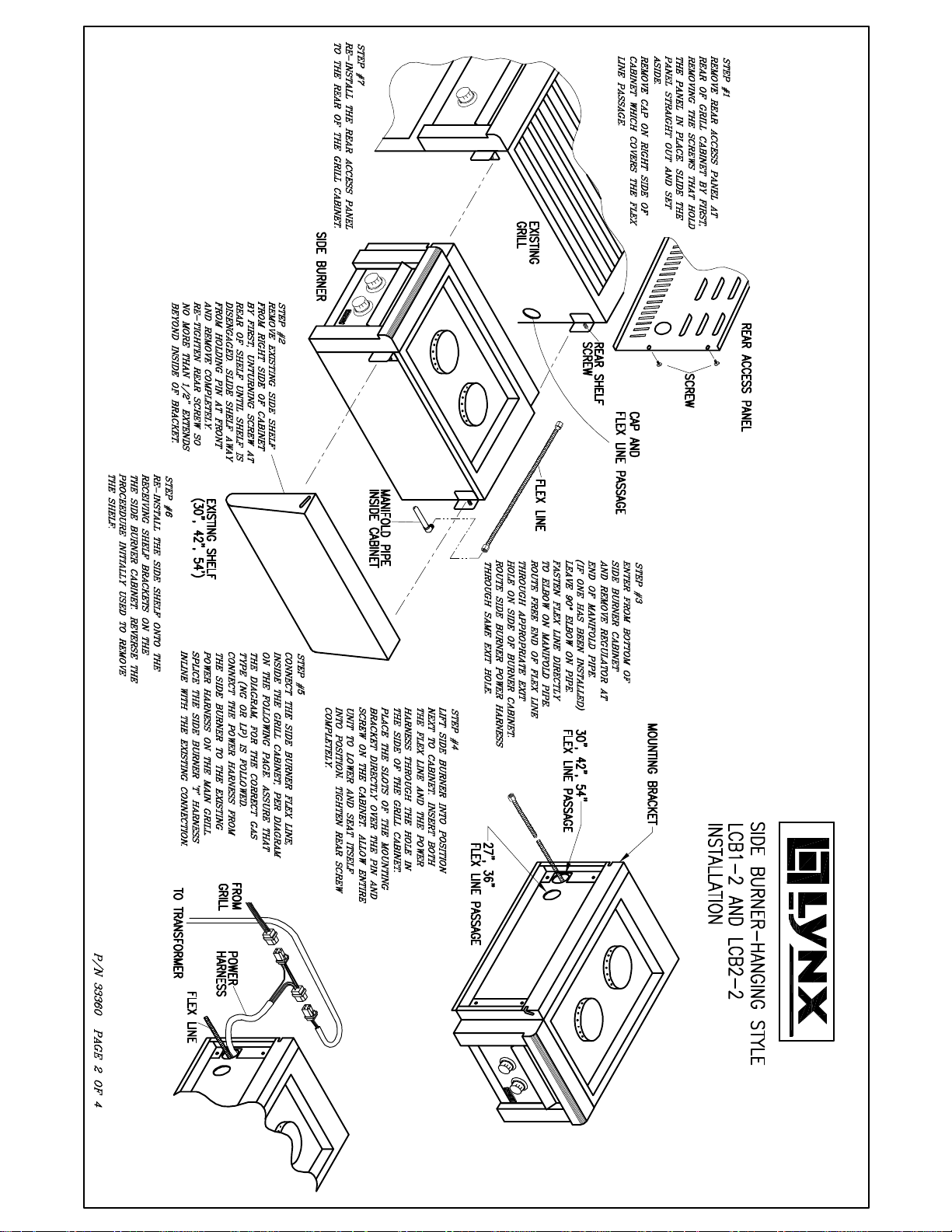
2. Grill cabinet preparation- remove ‘Rear Access Panel’, ‘Flex Line Cap’, and ‘Right Side Shelf’, as outlined in
steps I and 2 of Installation Diagram, from the main grill cabinet. A Phillips screw driver will be required for the
rear panel and shelf removal, and a flat screw driver will be needed to remove the cap.
3. Preparing and Hanging Side Burner- Follow steps 3 and 4 of the Installation Diagram to guide you through
the minor preparation required and the actual hanging of the side burner unit onto the grill cabinet.
4. Gas connections-Once the side burner unit is mounted onto the main grill cabinet, and the flex line and
power harness have been passed through into the cabinet, the gas and electrical connections will need to be
made. All necessary fittings have been supplied. Please refer to the LP and NG Gas Hook-up diagrams found
on pages 3 and 4 for all gas connections. Use the correct diagram for your gas type. All gas connections
must be made using plumbers putty or plumbers Teflon tape suitable for gas connections. All gas
connections must be checked for leaks using a soap solution of 3 parts water to one part detergent.
5. Electrical connections- connect the power harness from the side burner to the power harness found inside
the main grill cabinet. This connection is accomplished by first, separating the ‘Molex’ connectors which
completes the circuit from the main grill functions to the grill transformer. The power harness from the side
burner is formed in the shape of a ‘T’. The connectors at the ends of the ‘T’ splice into the separated
connectors from the grill. See step 5 and illustration found on the Installation Diagram. This connection
provides power, from the main grill transformer, to the ignition function and the blue LED operation of the side
burner. The blue LED lights for the side burner are now controlled by the light switch from the main grill. The
ignition function, of the side burner, however, is controlled at the side burner.
6. Side Shelf Installation- re-install the side shelf, that was originally removed from the main grill cabinet, onto
the new side burner. The installation technique used for the side burner is identical to that of the grill cabinet.
NOTE: if you are installing this side burner onto a 27” or 36”, the adaptor kit that is required for this
installation (LCB-BKT) comes with a new side shelf that will fit this side burner cabinet depth.
7. Rear Access Panel-re-install the rear access panel that was removed from the rear of the main grill cabinet.
P/N 33360 page 1 of 4
Page 2
Page 3

L.P. GAS HOOK-UP
Page 4

NATURAL GAS HOOK-UP
LP BULK-TANK HOOK-UP
 Loading...