

Page 1
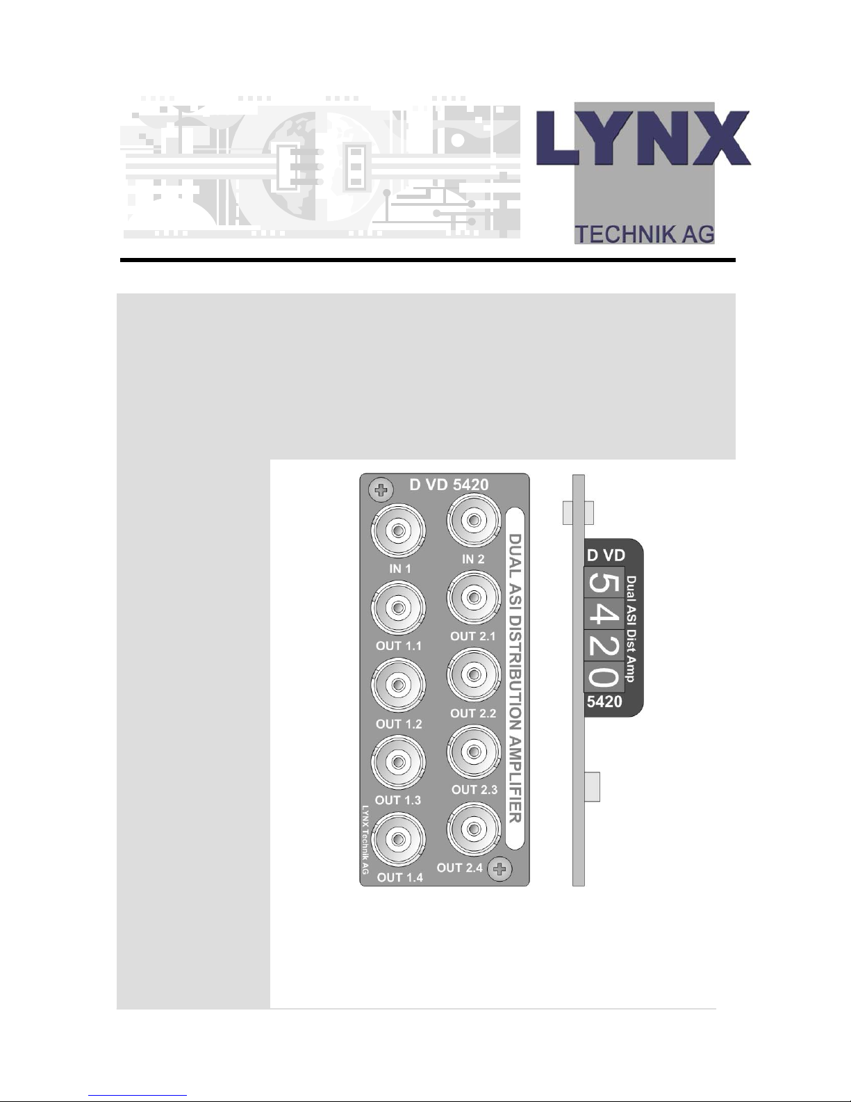
Series 5000
© LYNX Technik AG
Brunnenweg 3
D-64331 Weiterstadt
Germany
www.lynx-technik.com
Reference Manual
D VD 5420
Dual ASI/SDI Distribution Amplifier
CardModul
e
Version 1.0
Page 2

Reference Manual D VD 5420 Version 1.0
Page 2
Information in this document is subject to change without
notice. No part of this document may be reproduced or
transmitted in any form or by any means, electronic or
mechanical for any purpose, without express written permission
of LYNX Technik AG.
LYNX Technik AG may have patents, patent applications,
trademarks, copyrights or other intellectual property rights
covering the subject matter in this document. Except as
expressly written by LYNX Technik AG, the furnishing of this
document does not give you any license to patents,
trademarks, copyrights or other intellectual property of LYNX
Technik AG or any of its affiliates.
© LYNX Technik AG 2005 all rights reserved
Page 3

Reference Manual D VD 5420 Version 1.0
Page 3
Warranty
LYNX Technik AG warrants that the product will be free from
defects in materials and workmanship for a period of two (2)
year from the date of shipment. If this product proves defective
during the warranty period, LYNX Technik AG at its option will
either repair the defective product without charge for parts and
labor, or will provide a replacement in exchange for the
defective product.
In order to obtain service under this warranty, customer must
notify LYNX Technik of the defect before expiration of the
warranty period and make suitable arrangements for the
performance of service. Customer shall be responsible for
packaging and shipping the defective product to the service
center designated by LYNX Technik, with shipping charges
prepaid. LYNX Technik shall pay for the return of the product to
the customer if the shipment is within the country which the LYNX
Technik service center is located. Customer shall be responsible
for payment of all shipping charges, duties, taxes and any other
charges for products returned to any other locations.
This warranty shall not apply to any defect, failure, or damage
caused by improper use or improper or inadequate
maintenance and care. LYNX Technik shall not be obligated to
furnish service under this warranty a) to repair damage resulting
from attempts by personnel other than LYNX Technik
representatives to install, repair or service the product; b) to
repair damage resulting from improper use or connection to
incompatible equipment; c) to repair any damage or
malfunction caused by the use of non LYNX Technik supplies; or
d) to service a product which has been modified or integrated
with other products when the effect of such modification or
integration increases the time or difficulty servicing the product.
THIS WARRANTY IS GIVEN BY LYNX TECHNIK WITH RESPECT TO THIS
PRODUCT IN LIEU OF ANY OTHER WARRANTIES, EXPRESS OR
IMPLIED. LYNX TECHNIK AND ITS VENDORS DISCLAIM ANY IMPLIED
WARRANTIES OF MERCHANTABILITY OR FITNESS FOR A PARTICULAR
PURPOSE. LYNX TECHNIK`S RESPONISIBILITY TO REPAIR AND
REPLACE DEFECTIVE PRODUCTS IS THE SOLE AND EXCLUSIVE
REMEDY PROVIDED TO THE CUSTOMER FOR BREACH OF THIS
WARRANTY. LYNX TECHNIK AND ITS VENDORS WILL NOT BE LIABLE
FOR ANY INDIRECT, SPECIAL, INCIDENTAL, OR CONSEQUENTAL
DAMAGES IRRESPECTIVE OF WHETHER LYNX TECHNIK OR THE
VENDOR HAS ADVANCE NOTICE OF THE POSSIBILITY OF SUCH
DAMAGES.
Page 4

Reference Manual D VD 5420 Version 1.0
Page 4
Regulatory information
Europe
Declaration of Conformity
USA
FCC 47 Part 15
This device complies with part 15 of the FCC Rules. Operation is
subject to the following two conditions: (1) This device may not
cause harmful interference, and (2) this device must accept any
interference received, including interference that may cause
undesired operation.
Note: This equipment has been tested and found to comply with the
limits for a Class A digital device, pursuant to the part 15 of the FCC
Rules. These limits are designed to provide reasonable protection
against harmful interference when the equipment is operated in a
commercial environment. This equipment generates, uses, and can
radiate radio frequency energy and, if not installed and used in
accordance with the instruction manual, may cause harmful
interference to radio communications. Operation of this equipment in
a residential area is likely to cause harmful interference in which case
the user will be required to correct the interference at his own
expense.
We LYNX Technik AG
Brunneweg 3
D-64331 Weiterstadt
Germany
Declare under our sole responsibility that the product
TYPE: D VD 5420
To which this declaration relates is in conformity with the following
standards (environments E1-E3):
EN 55103-1 /1996
EN 55103-2 /1996
EN 60950 /2001
Following the provisions of 89/336/EEC and 73/23/EEC directives.
Winfried Deckelmann
Weiterstadt, November 2005
Place and date of issue Legal Signature
Page 5

Reference Manual D VD 5420 Version 1.0
Page 5
Contents
Warranty .................................................................. 3
Regulatory information........................................... 4
Europe .............................................................................4
Declaration of Conformity.......................................... 4
USA.................................................................................4
FCC 47 Part 15............................................................4
Contents .................................................................. 5
Getting Started........................................................ 7
Packaging........................................................................7
Product Description ........................................................7
Functional Diagram ........................................................8
Module Layout................................................................ 8
Connections.......................................................... 10
Video Connections........................................................10
Installation ............................................................. 11
Settings and Control ............................................. 12
Multi Function Switch ..................................................13
Using the Local Display Menus.................................... 14
Navigation.................................................................14
Menu Structure..............................................................14
Auto Store ................................................................. 15
Auto Store ................................................................. 16
Alarm/LED Status Indicators................................. 17
Channel Condition Indicators ...................................17
Alarm Indicator.........................................................17
Locate Function ........................................................18
Specifications (D VD 5420) .................................. 19
Available Options................................................. 20
Parts List.................................................................. 20
Service ................................................................... 21
Contact Information ............................................. 22
Page 6

Reference Manual D VD 5420 Version 1.0
Page 6
This page is intentionally left blank
Page 7

Reference Manual D VD 5420 Version 1.0
Page 7
Getting Started
Packaging
The shipping carton and packaging materials
provide protection for the module during transit.
Please retain the shipping cartons in case
subsequent shipping of the product becomes
necessary.
Product Description
The D VD 5420 is a high quality digital video (ASI
and SDI) distribution amplifier designed primarily for
broadcast and professional applications.
The flexible architecture allow the D VD 5420 to be
used in multiple configurations. Outputs can be
individually set to reclocked or non-reclocked,
inverted or non-inverted and each output can be
individually assigned to one of the two inputs.
Programmed presets allow for quick and easy
configurations, e.g. 2 x 1->4 operation.
Therefore the D VD 5420 can handle SDI signals as
well as ASI/DVB/SMPTE 310 signals.
The D VD 5420 is part of the 5000 series of
CardModules, which offer high quality, modularity
and flexibility in a small form factor ideal for
applications where space is at a premium.
CardModules are installed in the series 5000 card
frame that can accommodate up to 10
CardModules. All modules are hot swappable and
Options include full redundant power and a range
of controller options.
Page 8
Reference Manual D VD 5420 Version 1.0
Page 8
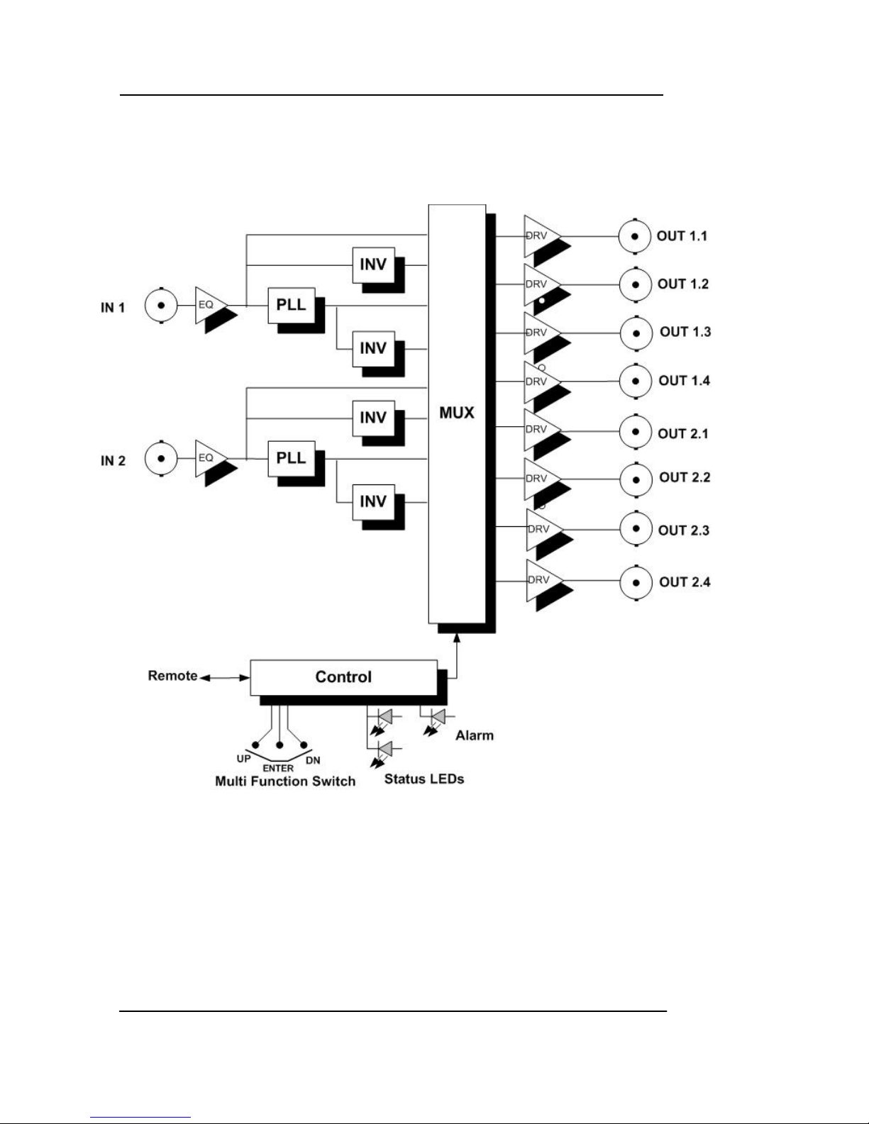
Functional Diagram
Figure 1 below is the basic functional diagram for
the D VD 5420 CardModule.
Figure 1- D VD 5420 Functional Diagram
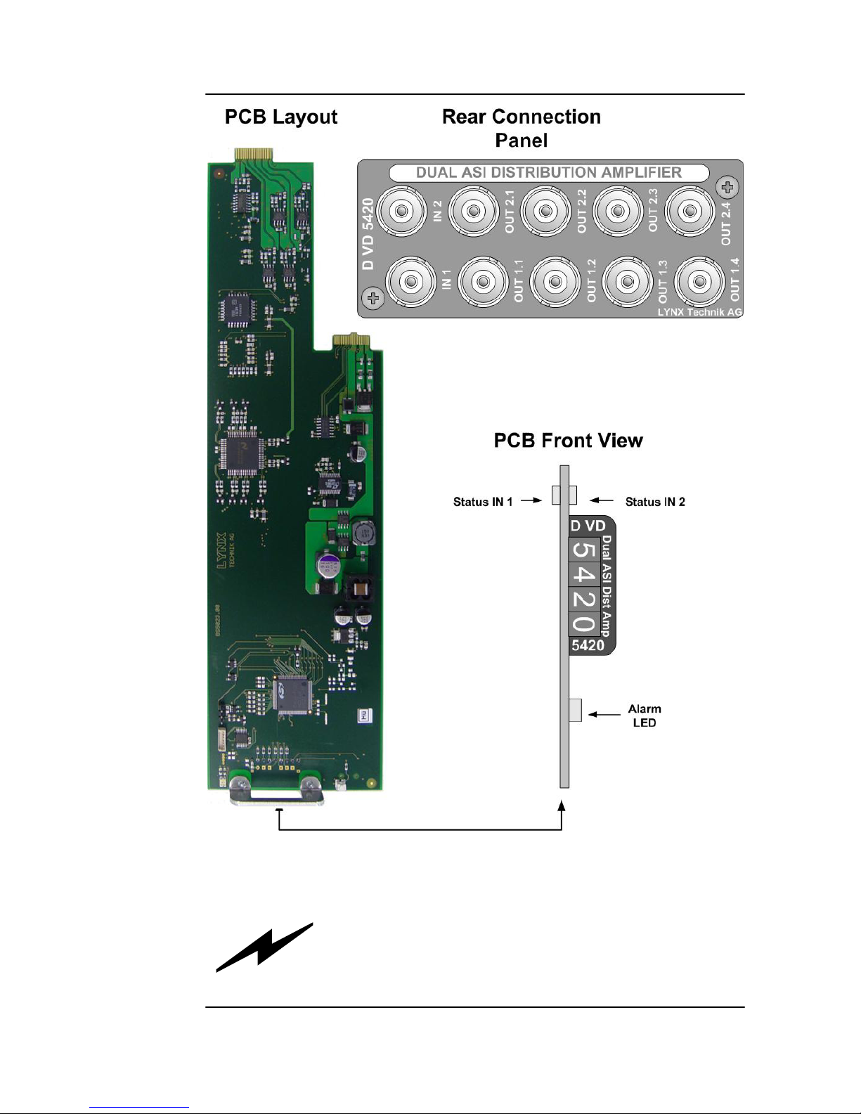
Module Layout
Figure 2 shows the layout of the D VD 5020
CardModule and the rear connection panel.
Please refer the connections section of this manual
for wiring details for the connectors.
Page 9
Reference Manual D VD 5420 Version 1.0
Page 9
Figure 2 – Module Layout
Caution
Use static precautions when handling the
PCB. Static discharge could result in serious
damage to the module.
Page 10

Reference Manual D VD 5420 Version 1.0
Page 10
Connections
Video Connections
The D VD 5420 CardModule is configured with
standard 75 Ohm BNC connectors. Connection is
self-explanatory. We recommend the use of high
quality video cable for digital video connections to
reduce the risk of interference or errors due to
excessive cable attenuation.
Note. Due to the compact design of the
connection plate it will be necessary to use a
connection tool to secure the BNC video
connectors.
Page 11

Reference Manual D VD 5420 Version 1.0
Page 11
Installation
Caution
The CardModule is shipped in a
protective anti-static bag. Please take
suitable precautions to avoid static
discharge onto any part of the PCB or
components when handling module or
serious damage could result.
Each Card Module is supplied with a rear
connection panel and two mounting screws.
Please follow the following procedure for
installation of the card module into the Series 5000
Card Frame.
a) Select a slot in the card frame where the
CardModule will be located
b) Remove the blank connection panel from the
rear of the rack (if fitted)
c) Install the rear connection panel using the
screws supplied. Do not tighten the screws fully
d) Slide the card module into the card frame and
carefully check the CardModule easily
connects to the rear connection plate. The
card should fit easily and should not require
excessive force to insert, if you feel any
resistance, there could be something wrong
with the rear connection panel location. Do not
try and force the connection. Remove the rear
connection panel and check alignment with
the CardModule.
e) Insert and remove the CardModule a few times
to ensure correct alignment and then tighten
the two screws to secure the rear connection
plate
Page 12
Reference Manual D VD 5420 Version 1.0
Page 12
Settings and Control
The D VD 5420 has an integrated micro-controller,
which enables the module to be configured and
controlled locally using the multifunction switch and
4 character dot matrix display, or from remote
when using one of the optional controllers and
control software.
Once set, all settings are automatically saved in
non-volatile internal memory. (Flash ram) The
module will always recall the settings used prior to
power down.
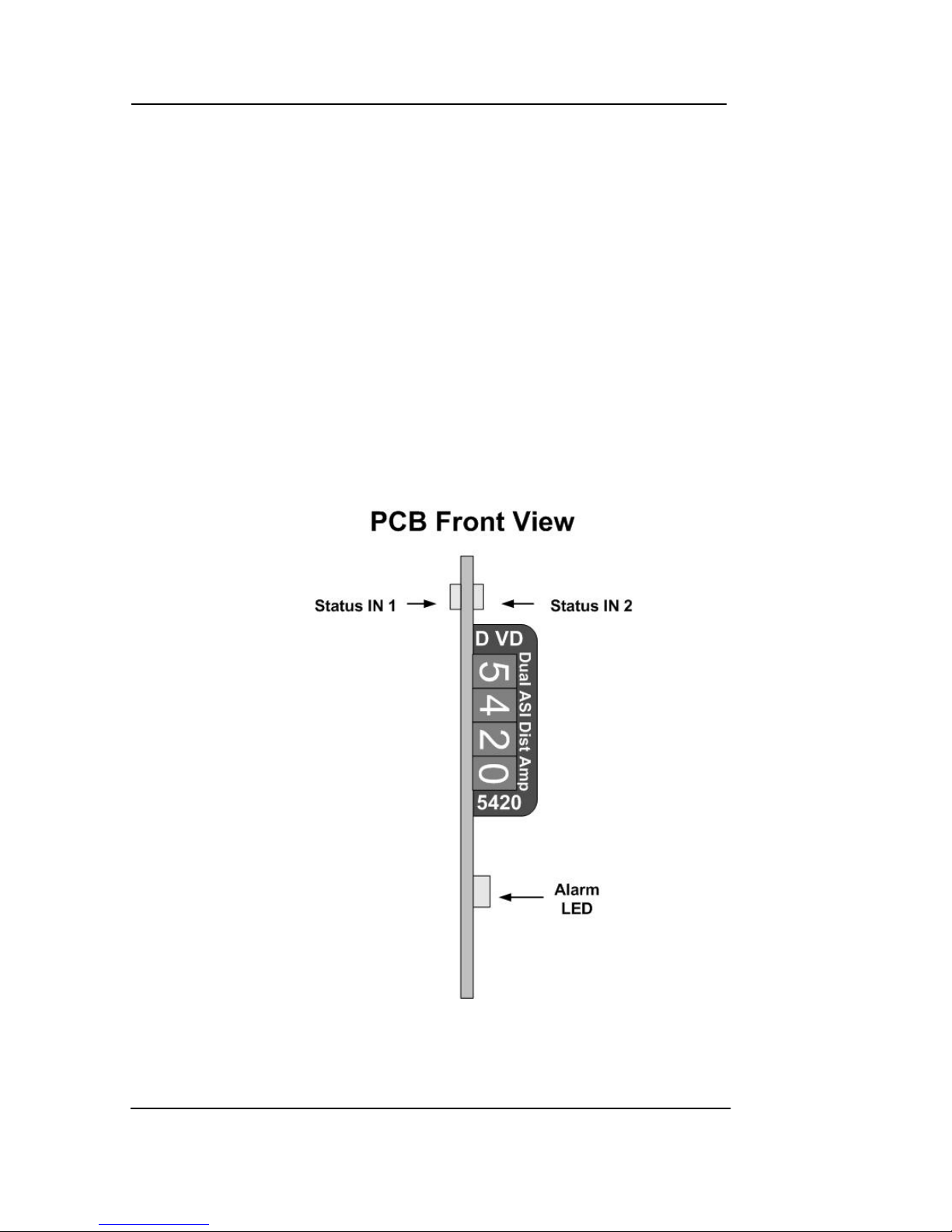
Figure 3 – Switch and Display Location
Page 13
Reference Manual D VD 5420 Version 1.0
Page 13
Multi Function Switch
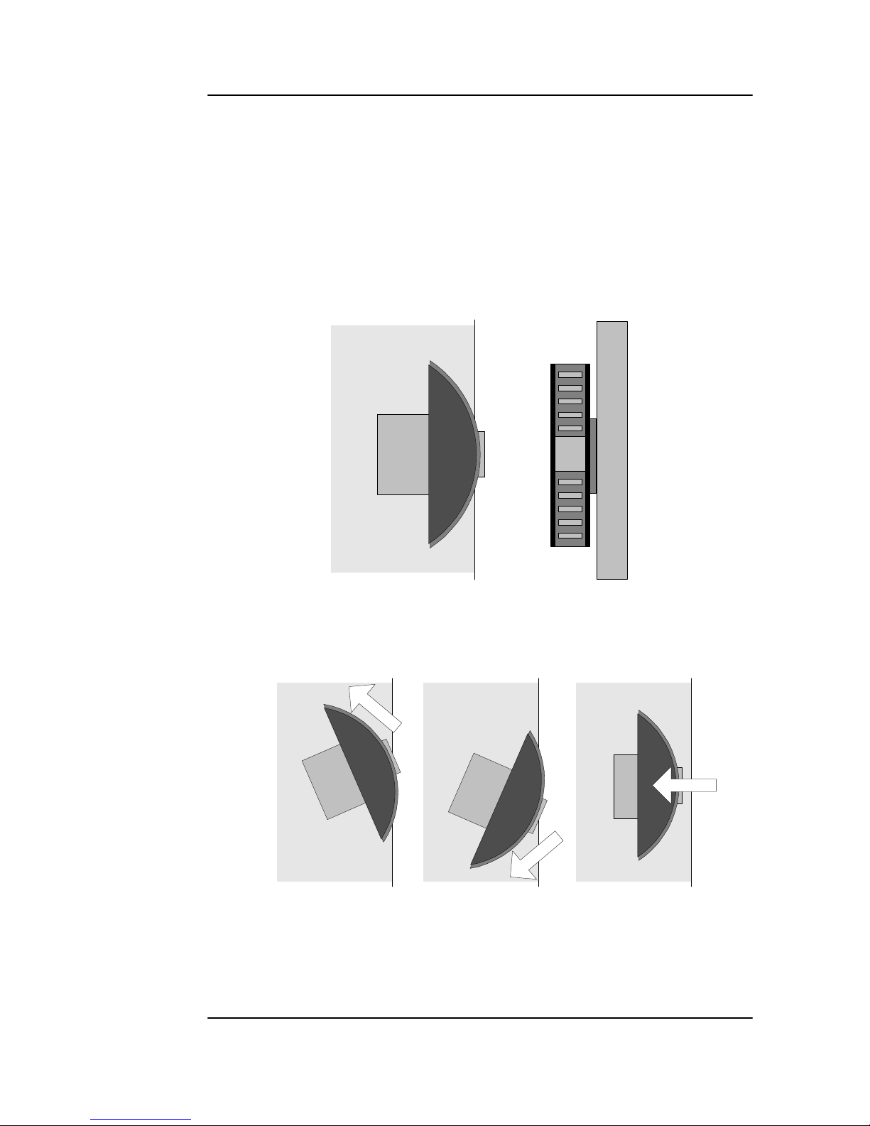
The CardModule is equipped with a multi-function
switch located on the front bottom edge of the
card (refer to figure 3)
Figure 4 – Switch Operation
Up Down
Enter
Switch Operations
Multi-function Switch
Side Front
Page 14
Reference Manual D VD 5420 Version 1.0
Page 14
Using the Local Display Menus
Making local adjustments to the module is done
using the multifunction switch and the integrated 4character dot matrix display (figure 3). The menu
system is layered, and navigation through the
system is done using the UP and DOWN functions of
the switch. ENTER is used to move between menu
levels and also enter a selection.
Navigation
Menu Structure
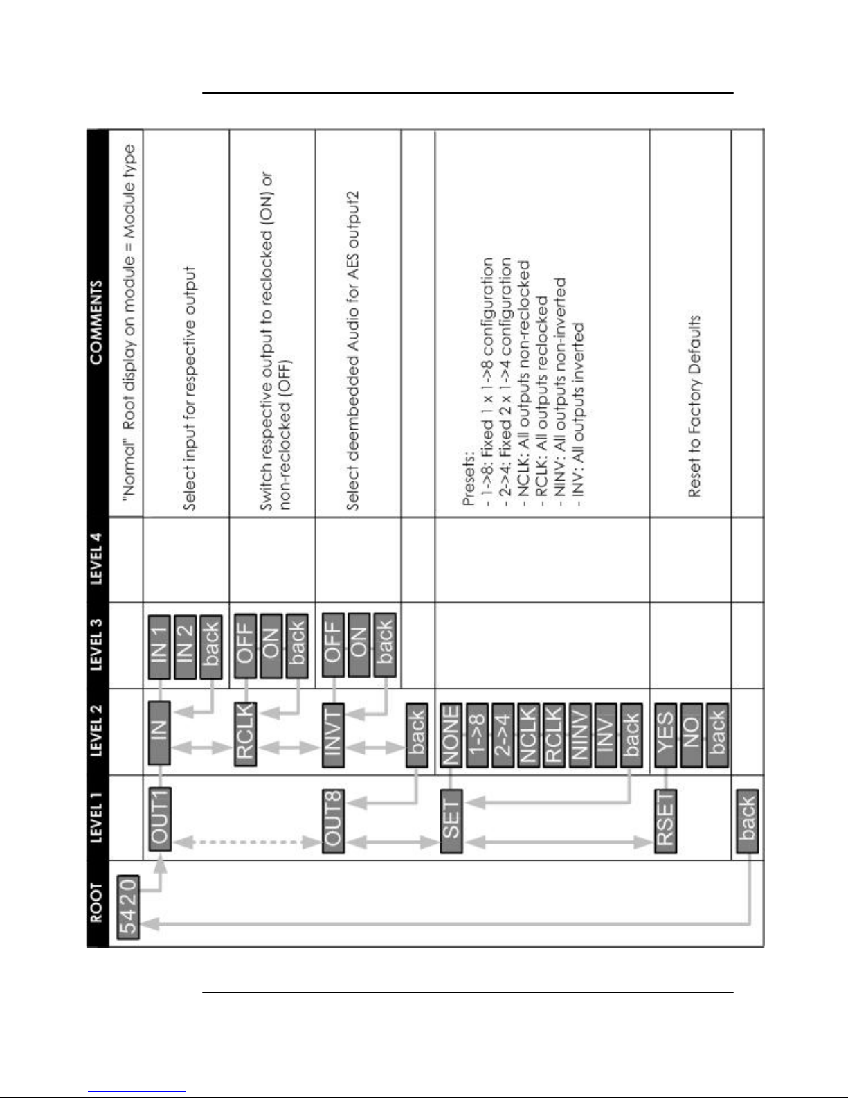
The Menu structure is defined in the next table, and
should be used when navigating through the
system.
Notes / Tips.
ENTER moves between Levels
UP/DOWN moves between items within the level
When you enter a new setting the system will jump
back one level in the menu system.
• The “back” selection in the menu structure will
take you back one level when selected.
• When an item is selected which has several
setting possibilities the first value displayed will be
the value currently stored in the system. The
order of the available settings for any menu item
in the table supplied does not represent the
order he settings will actually be displayed.
• If left unattended, the menu will default to the
root display after a preset timeout.
Switch Function Operation
UP Move UP within a level
DOWN Move down within a level
ENTER Change levels / Make selection
Page 15
Reference Manual D VD 5420 Version 1.0
Page 15
Page 16

Reference Manual D VD 5420 Version 1.0
Page 16
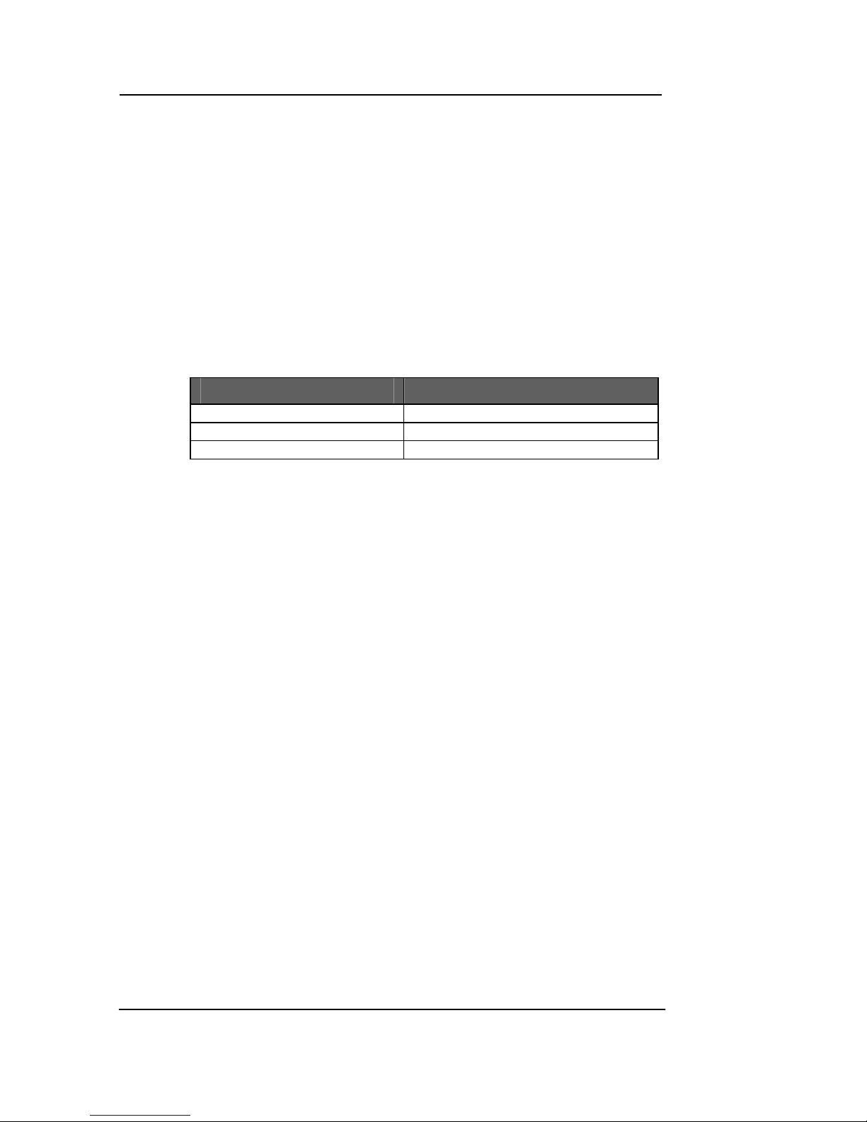
Auto Store
If no parameters are changed for 10 seconds then
the current settings will be written into flash memory
automatically, this can be seen by the channel
status LEDS flashing yellow four times.
Page 17
Reference Manual D VD 5420 Version 1.0
Page 17
Alarm/LED Status Indicators
The D VD 5420 module has integral LED indicators,
which serve as alarm and status indication for the
module. Function is described below.
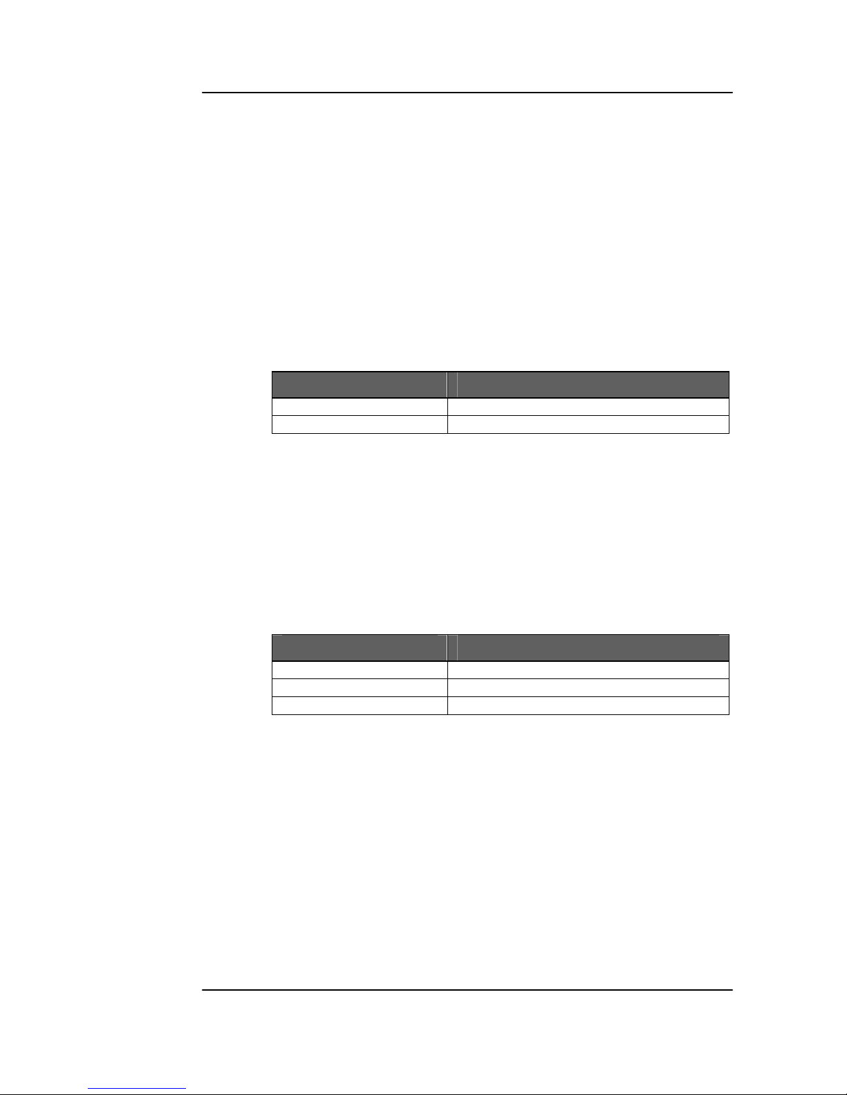
Channel Condition Indicators
2 status LEDs are provided on the top edge of the
module, one for each channel (figure 3)
Alarm Indicator
There is also a single alarm LED on the lower edge
of the module (figure 3). This is visible through the
card frame front cover and provides a general
indication of the module status.
LED OFF indicates power is lost, or there is a power
supply fault.
LED Color Indication
Green Input Present
Red Input Lost
LED Color Indication
Green Signal Present (locked)
Yellow Only one input signal is present
Red Input signal lost
Page 18
Reference Manual D VD 5420 Version 1.0
Page 18
Locate Function
For larger systems which may have multiple cards
of the same type in a single rack, or multiple rack
systems on a large central control system we have
added a useful utility which will help to visually
locate a suspect module quickly (When used in
conjunction with the optional control system and
software)
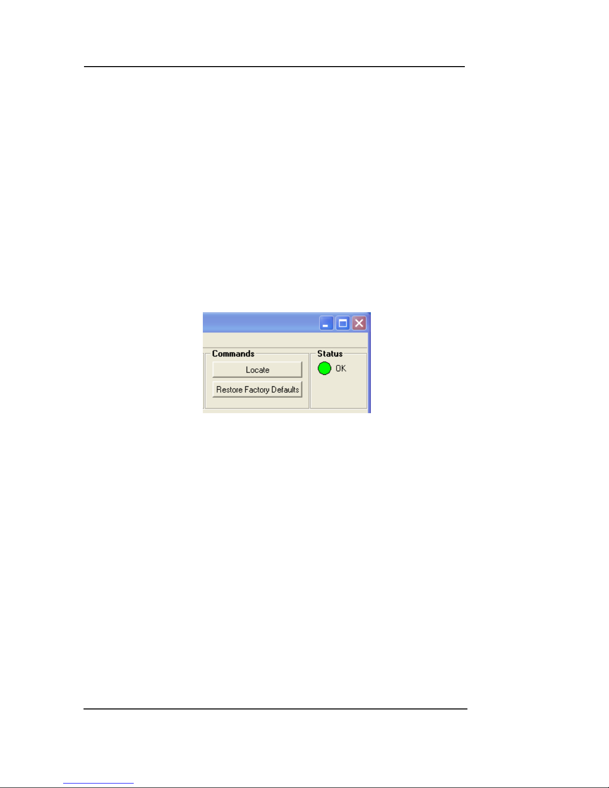
Once the specific module has been selected on
the control system there is a locate button on the
top of the GUI:
Locate Function in Control System
When Locate is selected the status indicator on the
GUI and the alarm LED will flash yellow in the
following continuous sequence.
3 short flashes…. Pause…. 3 short flashes …
Use of the locate function will not interfere with the
normal operation of the module.
For more details on this feature please check the
documentation supplied with the controller
software.
Page 19

Reference Manual D VD 5420 Version 1.0
Page 19
Specifications
(D VD 5420)
Inputs
Signal 1 or 2 Serial Digital Video. SMPTE 259M-C or
ASI/DVB/SMPTE 310 (5-622 MBit)
Input Impedance 75 Ohms
Input level 0.8V p-p
Return loss > 15dB (270MHz)
Connection BNC
Outputs
Signal 8 Serial Digital Video
Output Impedance 75 Ohms
Output Level 0.8V p-p nom.
Return loss > 15dB (270 Mbit/s)
Connection BNC
Operating Modes
Preset “Dual” 2 x 1:4 (reclocked or non clocked)
Preset “Single”
Individual
1 x 1:8 (reclocked or non clocked)
Each output can be configured independently:
- select input, reclocked/non-reclocked,
inverted/non-inverted
Performance
Cable Equalization Up to 250m using Belden 8281 (270Mbit/s)
Jitter < 0.2 UI
Control Local settings (matrix display and multifunction
switch).
Status Monitoring (LED) Signal presence and PLL lock indication
Electrical Specifications
Operating Voltage + 5VDC
Power Consumption 3.5 W
Safety
IEC 60950/ EN 60950/VDE 0805
Mechanical
Size 283mm x 78mm
Weight Card module 120g, connection panel 50g
Ambient
Temperature 5°C to 40°C Maintaining specifications
Humidity Max 90% non condensing
Supplied Accessories
Documentation D VD 5420 Reference Manual
Page 20
Reference Manual D VD 5420 Version 1.0
Page 20
Available Options
Below is a list of related products for the D VD 5420
CardModule. Please refer to product brochures or
our web site for more detailed information.
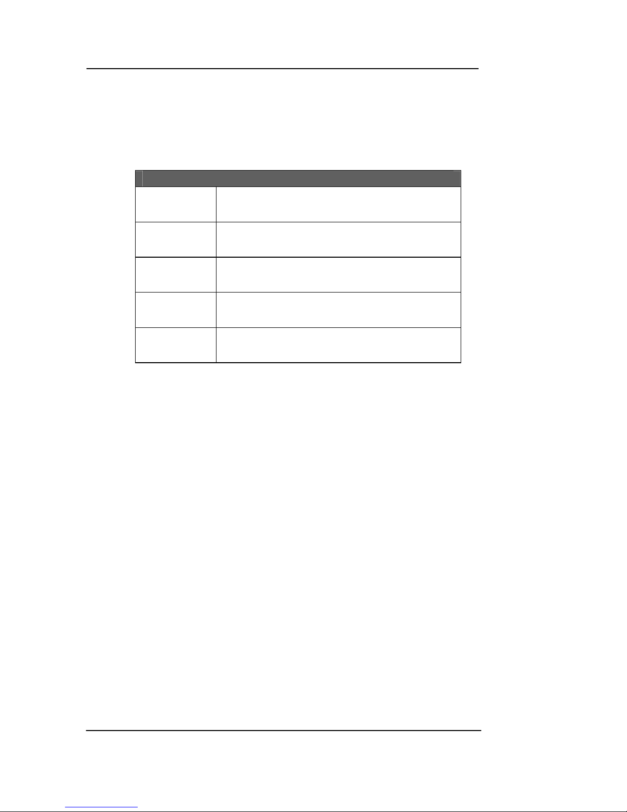
Model Description
R FR 5010
Series 5000 Rack Frame (empty) with single
power supply
R PS 5010
Redundant power supply for the R FR 5010
Card Frame
R CT 5020
Rack controller for the R FR 5010 Card
Frame
R CT 5030
Master controller with TCP/IP interface for
the R FR 5010 Card Frame
R CT 5010
Rack Bus Extension for the R FR 5010 Card
Frame. In combination with R CT 5020/5030
Parts List
Due to the very dense design and miniature
surface mount technology the module is not field
serviceable. The information for a replacement
assembly is below.
D VD 5420 CardModule (complete)
Description Dual SDI Distribution Amplifier
Model Number D VD 5020
Part Number 5.155.000.020
Sub Assemblies:
D VD 5420 Processing Board only. (BS 5023_B)
Part Number 5.155.003.005
Rear Connection Panel for D VD 5420 (MA5001_B)
Part Number 6.155.008.371
Page 21

Reference Manual D VD 5420 Version 1.0
Page 21
Service
If you are experiencing problems, or have questions
concerning your D VD 5420 CardModule please
contact your local distributor for assistance.
We offer a fixed cost service exchange program for
defective Series 5000 CardModules out of
Warranty. Please contact your distributor or check
our web site for details on this program.
More detailed information and product updates
may be available on our web site:
www.lynx-technik.com
You will also find links to contact us directly for
assistance.
Page 22
Reference Manual D VD 5420 Version 1.0
Page 22
Contact Information
Please contact your local distributor; this is your
local and fastest method for obtaining support and
sales information.
LYNX Technik can be contacted directly using the
information below.
Address LYNX Technik AG
Brunnenweg 3
D-64331 Weiterstadt
Germany.
Website www.lynx-technik.com
LYNX Technik manufactures a complete range of
high quality modular products for broadcast and
Professional markets, please contact your local
representative or visit our web site for more product
information.
Page 23

Reference Manual D VD 5420 Version 1.0
Page 23
Notes
 Loading...