

Page 1

Reference Manual
D VA 3720, D VA 3720 L
Dual Analog Video Distribution Amplifier
MiniModules
Series 3000
Hwww.lynx-technik.com
© LYNX Technik AG
Brunnenweg 3
64331 Weiterstadt
Germany
Page 2

Reference Manual D VA 3720 Version1.0
Information in this document is subject to change without
notice. No part of this document may be reproduced or
transmitted in any form or by any means, electronic or
mechanical for any purpose, without express written permission
of LYNX Technik AG.
LYNX Technik AG may have patents, patent applications,
trademarks, copyrights or o ther intellectual property rights
covering the subject matter in this document. Except as
expressly written by LYNX Technik AG, the furnishing of this
document does not give you any license to patents,
trademarks, copyrights or other intellectual property of LYNX
Technik AG or any of its affiliates.
© LYNX Technik AG 2007-2008 all rights reserved
RoHs Conformity
The RoHS Directive stands for "the
restriction of the use of certain
hazardous substances in electrical
and electronic equipment". This
Directive bans the placing on the EU
market of new electrical and
electronic equipment containing
more than agreed levels of lead,
cadmium, mercury, hexavalent
biphenyl (PBB) and polybrominated diphenyl ether (PBDE) flame
retardants.
This product conforms to EU RoHS Directives 2002/95/EC
chromium, polybrominated
Page 2
Page 3

Warranty
LYNX Technik AG warrants that the product will be free from
defects in materials and workmanship for a period of two (2)
years from the date of shipment. If this product proves defective
during the warranty period, LYNX Technik AG at its option will
either repair the defective product without charge for parts and
labor, or will provide a replacement in exchange for the
defective product.
In order to obtain service under this warranty, customer must
notify LYNX Technik of the defect before expiration of the
warranty period and make suitable arrangements for the
performance of service. Customer shall be responsible for
packaging and shipping the defective product to the service
center designated by LYNX Technik, with shipping charges
prepaid. LYNX Technik shall pay for the return of the product to
the customer if the shipment is within the country which the LYNX
Technik service center is located. Customer shall be responsible
for payment of all shipping charges, duties, taxes and any other
charges for products returned to any other locations.
This warranty shall not apply to any defect, failure, or damage
caused by improper use or improper or inadequate
maintenance and care. LYNX Technik shall not be obligated to
furnish service under this warranty a) to repair damage resulting
from attempts by personnel other than LYNX Technik
representatives to install, repair or service the product; b) to
repair damage resulting from improper use or connection to
incompatible equipment; c) to repair any damage or
malfunction caused by the use of non LYNX Technik supplies; or
d) to service a product which has been modified or integrated
with other products when the effect of such modification or
integration increases the time or difficulty servicing the product.
THIS WARRANTY IS GIVEN BY LYNX TECHNIK WITH RESPECT TO THIS
PRODUCT IN LIEU OF ANY OTHER WARRANTIES, EXPRESS OR
IMPLIED. LYNX TECHNIK AND ITS VENDORS DISCLAIM ANY IMPLIED
WARRANTIES OF MERCHANTABILITY OR FITNESS FOR A PARTICULAR
PURPOSE. LYNX TECHNIK`S RESPONISIBILITY TO REPAIR AND
REPLACE DEFECTIVE PRODUCTS IS THE SOLE AND EXCLUSIVE
REMEDY PROVIDED TO THE CUSTOMER FOR BREACH OF THIS
WARRANTY. LYNX TECHNIK AND ITS VENDORS WILL NOT BE LIABLE
FOR ANY INDIRECT, SPECIAL, INCIDENTIAL, OR CONSEQUENTIAL
DAMAGES IRRESPECTIVE OF WHETHER LYNX TECHNIK OR THE
VENDOR HAS ADVANCE NOTICE OF THE POSSIBILITY OF SUCH
DAMAGES.
Reference Manual D VA 3720 Version1.0
Page 3
Page 4

Reference Manual D VA 3720 Version1.0
Regulatory information
Europe
Declaration of Conformity
We LYNX Technik AG
Brunnenweg 3
D-64331 Weiterstadt
Germany
Declare under our sole responsibility that the product
TYPE: D VA 3720, D VA 3720 L
To which this declaration relates is in conformity with the following
standards (environments E1-E3):
EN 55103-1 /1996
EN 55103-2 /1996
EN 60950 /2001
following the provisions of 89/336/EEC and 73/23/EEC directives.
Winfried Deckelmann
Weiterstadt, November 2007
Place and date of issue Legal Signature
USA
Page 4
FCC 47 Part 15
This device complies with part 15 of the FCC Rules. Operation is
subject to the following two conditions: (1) This device may not
cause harmful interference, and (2) this device must accept any
interference received, including interference that may cause
undesired operation.
Note: This equipment has been tested and found to comply with the
limits for a Class A digital device, pursuant to the part 15 of the FCC
Rules. These limits are designed to provide reasonable protection
against harmful interference when the equipment is operated in a
commercial environment. This equipment generates, uses, and can
radiate radio frequency energy and, if not installed and used in
accordance with the instruction manual, may cause harmful
interference to radio communications. Operation of this equipment in
a residential area is likely to cause harmful interference in which case
the user will be required to correct the interference at his own
expense
Page 5

Contents
Warranty ............................................................................................... 3
Regulatory information........................................................................ 4
Europe............................................................................................... 4
Declaration of Conformity ............................................................. 4
USA ................................................................................................... 4
FCC 47 Part 15 ............................................................................ 4
Contents ............................................................................................... 5
Getting Started ..................................................................................... 7
Packaging ......................................................................................... 7
Product Description ........................................................................... 7
Functional Diagram ........................................................................... 8
Module Layout ................................................................................... 8
Connections ....................................................................................... 10
Video Connections .......................................................................... 10
Installation .......................................................................................... 13
Mechanical ...................................................................................... 13
Stand Alone Operation ............................................................... 13
Multiple Units .............................................................................. 14
Electrical Installation. ...................................................................... 15
Stand Alone Operation ............................................................... 15
Multiple Units .............................................................................. 16
Settings and Control .......................................................................... 16
Switch Settings ................................................................................ 16
Switch Function Detail ................................................................ 17
Factory Preset Condition ............................................................ 17
Adjustment Procedures ................................................................... 18
Set Dual 1:4 or 1:8 mode (D VA 3720) ....................................... 19
Set Video Gain ........................................................................... 20
Set Equalization ......................................................................... 21
Set Unity Gain ............................................................................ 22
Set Unity Equalization ................................................................ 23
Auto Store .................................................................................. 23
Alarm/LED Status Indicators ............................................................. 24
Channel Condition Indicators ..................................................... 24
Front Panel Alarm Indicator ........................................................ 24
Locate Function .......................................................................... 25
Specifications (D VA 3720) ................................................................ 26
Available Options ............................................................................... 27
Parts List............................................................................................. 28
Service ................................................................................................ 28
Contact Information ........................................................................... 29
Reference Manual D VA 3720 Version1.0
Page 5
Page 6

Reference Manual D VA 3720 Version1.0
This Page is intentionally left blank
Page 6
Page 7

Getting Started
Packaging
The shipping carton and packaging materials
provide protection for the module during transit.
Please retain the shipping cartons in case
subsequent shipping of the product becomes
necessary.
Product Description
The D VA 3720 / D VA 3720 L is a high quality
analog video distribution amplifier designed
primarily for broadcast and professional
applications.
Flexible configurations allow the D VA 3720 to be
used in dual 1 to 4 applications or 1 to 8
applications, the D VA 3720 L has passive loop
through outputs for both inputs and 3 outputs per
channel. Both units are with independent gain and
equalization adjustment for each channel. The
module is microprocessor controlled and
configuration, gain level and equalization are set
using local controls included on the module. All
settings are stored in internal flash ram. Presence
detection is provided via status LEDs and a front
side alarm LED is also provided.
The D VA 3720 and D VA 320 L is part of the 3000
series of MiniModules, which offer high quality,
modularity and flexibility in a very small form factor
ideal for applications where space is at a premium.
The modules can be used either stand alone using
the optional power supply brick, or as part of a
tightly integrated space saving system wh ere up to
10 MiniModules can be mounted utilizing the
optional LYNX R FR 3005/3010 rack housing. This
includes integrated power supply and optional
remote control interfaces.
Reference Manual D VA 3720 Version1.0
Page 7
Page 8
Reference Manual D VA 3720 Version1.0
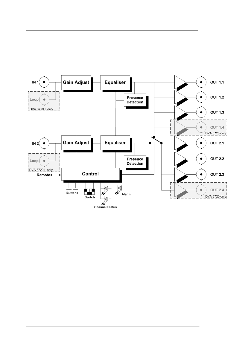
Functional Diagram
Figure 1 below is the basic functional diagram for
the D VA 3720 / 3720 L MiniModule.
Figure 1- D VA 3720 / 3720 L Functional Diagram
Module Layout
Figure 2 shows the physical layout of the D VA 3720
MiniModule. Video I/O is made through standard
BNC video connectors. Module configuration is set
via a small dip-switch and push buttons located
behind a small access hole in the bottom of the
module. When used in single mode (1x1:8) IN 1 is
used as the input signal.
If the module is being used in a stand alone
application then the optional power supply (R PS
3601 E, R PS 3601 U or R PS 3601-3) is required to
power the module (not shown)
Page 8
Page 9

DC Power
Connection
Channel 2
Status LED
Reference Manual D VA 3720 Version1.0
D VA 3720
s
e
l
o
h
n
o
i
t
a
l
i
t
n
e
v
e
h
t
t
c
u
r
t
s
b
o
t
o
n
o
D
.
N
O
I
T
U
A
C
e
VID IN 1
l
u
d
o
m
e
h
t
f
OUT 1.1
o
m
o
t
t
o
b
d
OUT 1.2
n
a
p
o
t
e
h
t
LYNX Technik AG
n
OUT 1.3
o
VID IN 2
OUT 2.1
OUT 2.2
OUT 2.3
OUT 1.4
OUT 2.4
Front Side
Bottom
Figure 2 – Module Layout
Alarm / Status LED
DUAL ANALOG VIDEO DIST AMP
Channel 1
Status LED
Made In Germany
www.lynx-technik.com
DIP SWITCHBUTTONS
UP DN
1
OFF
ON
432
Page 9
Page 10

Reference Manual D VA 3720 Version1.0
Connections
Video Connections
The D VA 3720 MiniModule is configured with
standard 75 Ohm BNC connectors. Connection is
self-explanatory. We recommend the use of high
quality video cable to reduce the risk of
interference or errors due to excessive cable
attenuation.
Note. Due to the compact design of the module it
will be necessary to use a connection tool to
secure the BNC video connectors to the module.
Page 10
Page 11

Power / Data Connections
Metal Lemo Connector
The LEMO connector has a metal key and can be
aligned by using the red dots on both connectors
and then pushed together until lock ed into place.
When joined correctly and locked this will provide a
very secure mechanical connection
Reference Manual D VA 3720 Version1.0
Making Your Own Power
Connections
LYNX provides an array of power options for the
Modules including various AC adapters, battery
adapters, rechargeable battery packs and DC/DC
converters. If you wish to connect your own power
source to the Testor then you will require a mating
connector. Please refer below for the part numbers.
Using the Metal connector
Lemo Mating Connector (Female) Lemo Part#
FGG.0B.305.CLAD42
You can source these from LYNX using the part
numbers above, or you can source from the
manufacturer directly (same part number)
Page 11
Page 12

Reference Manual D VA 3720 Version1.0
Please provide a clean + 5VDC supply @ 2,5A
a tolerance of + 4.95VDC to +5.10 VDC and a DC
output ripple of less than 50mV (under load
measured at the connector). We recommend the
use of screened power cable connecting the
screen to the ground pin.
DO NOT MAKE ANY CONNECTIONS TO
PINS 4 and 5 AS THESE ARE FOR DATA
CONNECTIONS (LYNX USE ONLY).
CONNECTING POWER TO THESE PINS
WILL RESULT IN MODULE DAMAGE.
!
Note.
Any failure or damage to the module as a
result of poor / incorrect connections by the
use of a non LYNX supplied power source (or adapter)
is not covered under warranty.
with
Page 12
Page 13

Installation
Mechanical
Stand Alone Operation
The D VA 3720 MiniModule can be used in a stand
alone application. There are two options for the use
of the module in this way.
a) Using the R FR 3005 Rack Frame 1 option. This
allows up to any 10 of the MiniM o dules to be
secured onto a rack frame assembly for 19 inch
rack mounting. This keeps the modules secured,
organized and out of the way. The R PS 3601
power brick option or the R FR 3010 option is
required to power each module. Please refer to
the R FR 3005 Reference Manual supplied with
this option for more details.
b) Single Use. The MiniModule can be powered
independently with the R PS 3601 option and
used in any location where this functionality is
required.
Caution. Care needs to be taken
when using the module in this way, as
it is not physically secured. Keep the
module away from the floor to avoid
!
If using more than one MiniModule in any
installation, the R FR 3005/3010 Rack frame
combination is highly recommended.
the risk of someone stepping or
tripping on the unit, and locate the
unit away from excessive sources of
heat and any sources or moisture.
Reference Manual D VA 3720 Version1.0
Page 13
Page 14

Reference Manual D VA 3720 Version1.0
Multiple Units
Most applications will require more than one
MiniModule, which can include any of the
available Series 3000 MiniModule product range.
There are two options for mounting multiple units.
a) Using the R FR 3005 Rack Frame option. This
allows up to any 10 of the MiniM o dules to be
secured onto a rack frame assembly for 19 inch
rack mounting. The R PS 3601 power brick
option or the R FR 3010 option is required to
power each module. Please refer to the R FR
3005 Reference Manual for more details.
b) Using the R FR 3010 Rack frame extension
option. Can be combined with the R FR 3005
Rack frame option. Each module plugs into a
connection bus, which provides common
power for all modules. (no R PS external power
supplies are needed). Remote contro l and
status monitoring of all modules is possible with
the addition of the R CT 5020 rack controller
and R CT 5030 master controller options. Please
refer to the respective reference manuals for
these options for details of mechanical
installation.
The very small size and density of the MiniModules
combined with the available rack frame options
allows the addition of a complex and custom signal
distribution system without taking any additional
front rack space. The rack frames are designed for
installation in the back of 19-inch racks where there
is normally plenty of available space. Ideal for
mobile truck installations and facility expansions
where space is at a premium.
Page 14
Page 15

Electrical Installation.
Stand Alone Operation
The MiniModule requires the R PS 3601 power brick
option for stand-alone operation. Three versions are
available R PS 3601 E for European markets, R PS
3601 U for the US markets or the universal R PS 36013 desk power supply . Please ensure you have the
correct power option for your region. The
connection to the module is made with a small 5pin connector (see above). Please make sure the
connection is solid and locked in place. A strain
relief is included within the module to prevent
excessive strain on the connection.
Signal connections should be made with care,
please ensure connections are correct and
compatible equipment is feeding / receiving the
signals from the module or damage can result.
Caution. Only use the optional Lynx R PS
3601 power modules. Ensure the 5-pin
power connector is locked securely in
!
!
place.
Caution. Care needs to be taken when
using the module in this way, if it is not
physically secured. Keep the module
away from the floor to avoid the risk of
someone stepping or tripping on the unit,
and locate the unit away from excessive
sources of heat and any sources or
moisture.
Reference Manual D VA 3720 Version1.0
Page 15
Page 16
Reference Manual D VA 3720 Version1.0
Multiple Units
When installing multiple MiniModule units it is
recommended you use the R FR 3005 Rack Frame 1
and/or R FR 3010 Rack Frame options. Please refer
to the documentation supplied with these options
for details on electrical installation.
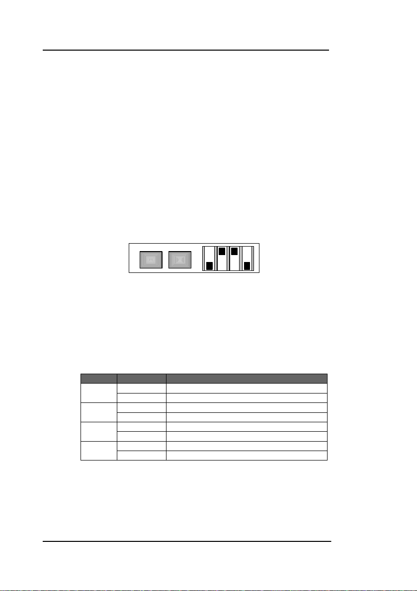
Settings and Control
The D VA 3720 is configured via the integral 4position dip-switch and push buttons.
DIP SWITCHBUTTONS
UP DN
Switch Settings
Below the switch settings for the 4-position dipswitch are defined. Switch function is described in
more detail after the table below.
Switch Setting Function
1
2
3
4
*When in single mode the IN 1 video input is used.
ON Single 1:8 mode *
OFF Dual 1:4 mode
ON Gain adjustment selected
OFF Equalizer adjustment selected
ON Unity selected
OFF Unity not selected
ON Channel 2 selected
OFF Channel 1 selected
OFF
ON
4321
Page 16
Page 17

Switch Function Detail
The switches are used as part of an adjustment
procedure and setting is not an implicit process.
Please refer to the alignment procedure section for
details on how to use the switches to set up the
module. The information below simply describes
function.
Dip Switch 1
This switch sets the configuration of the module. ON
sets single 1:8 mode. OFF sets dual 1:4 mode.
Dip Switch 2
This switch selects the parameter for adjustment
using the module push buttons. ON selects gain,
OFF selects equalization.
Dip Switch 3
This switch sets unity gain / equalization for the
module. ON selects unity, OFF allows for
adjustment.
Dip Switch 4
This switch selects the channel for adjustment. ON
selects channel 2, OFF selects chann el 1.
Factory Preset Condition
The D VA 3720 is delivered preset for the following
mode of operation:
Mode 2 x 1:4
Setting Unity Gain, Unity Equalization
If this is the mode of operation required, then no
adjustments are necessary.
Reference Manual D VA 3720 Version1.0
Page 17
Page 18
Reference Manual D VA 3720 Version1.0
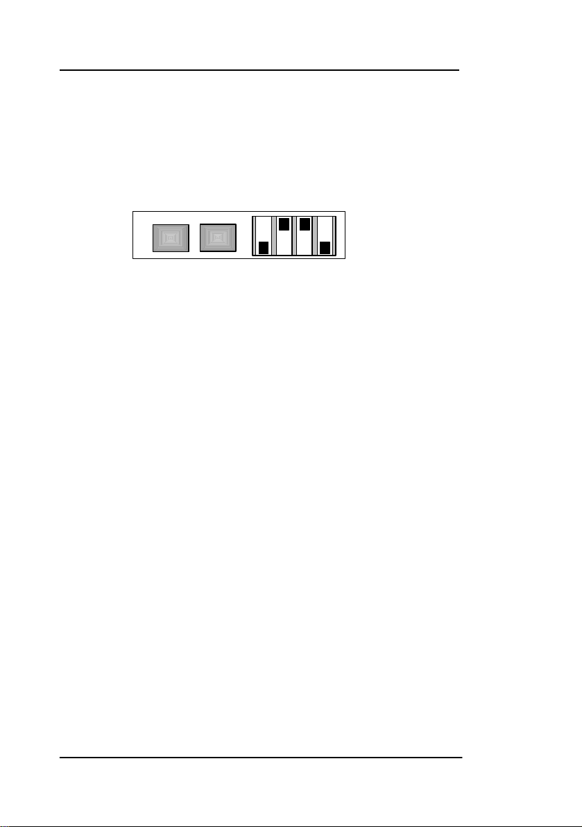
Adjustment Procedures
The modules configuration and gain/EQ settings
are set using combinations of the Dip Switch and
the two push buttons located on the module edge.
DIP SWITCHBUTTONS
UP DN 4
Setting functionality and calibration is interactive
and not an implicit switch setting process. The
adjustments are made through imbedded microcontroller and settings stored on internal flash ram.
To simplify the configuration and setting of the
module a series of procedures has been defined to
make setting the module easier. These are:
• Set Dual 1:4 or 1:8 Mode
• Set Video Gain
• Set Equalization
• Set Unity Gain
• Set Unity Equalization
These procedures capture most things you would
need to change or set on the module.
321
OFF
ON
Page 18
Page 19

Set Dual 1:4 or 1:8 mode (D VA 3720)
NOTE: For D VA 3820L it is 1:3 or 1:6 mode
The D VA 3720 module can be set to one of two
preset modes of operation.
Dual 1:4 Mode. This is a simple 2 x 1 to 4 video
amplifier. Independent channels passed through
the amplifier providing four outputs for each input
channel.
Single 1:8 Mode. This is a simple 1 x 1 to 8 Video
amplifier. The signal on the IN 1 input channel is
passed through the amplifier providing eight
outputs.
Use this procedure to select dual 1:4 or single 1:8
mode of operation.
1. Set Switch 1 to ON for 1:8 mode* or OFF for dual
1:4 mode
2. If 10 seconds pass with no further adjustment
both channel status LEDS will flash yellow four
times. This confirms setting has been written into
flash ram and stored.
When in 1: 8 mode the IN 2 channel indicator will go out.
*
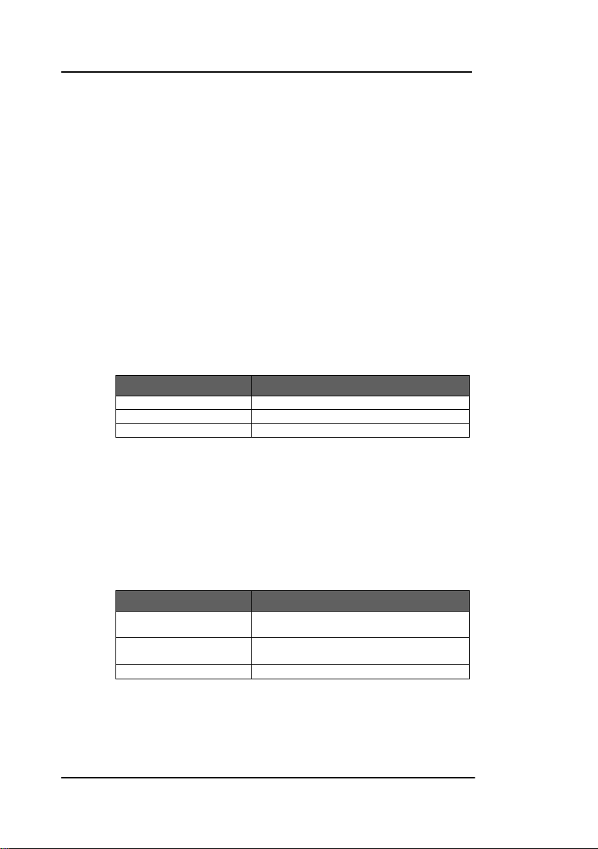
Note. Diagram only
shown for switch
location reference
not actual settings
UP DN 4
DIP SWITCHBUTTONS
OFF
ON
321
Reference Manual D VA 3720 Version1.0
Page 19
Page 20

Reference Manual D VA 3720 Version1.0
Set Video Gain
Use this procedure to set the video gain of the
module.
1. Set Switch 1 to desired mode of operation ON
for 1:8 mode or OFF for dual 1:4 mode
2. Set Switch 2
3. Set Switch 3
4. Set switch 4
channel to be adjusted ON for IN 2 and OFF for
IN 1* (respective LED will flash yellow once
indicating selected channel)
5. Push either the UP or DN push buttons to make
the necessary gain adjustment for the selected
channel.
6. If using dual mode, set switch 4 to select the
second channel and repeat 5 above.
7. If 10 seconds pass with no further adjustments
being made both channel statu s LEDS will flash
yellow four times. This confirms settings have
been written into flash ram and stored.
* This switch is only used / functional when the module is
configured for dual 1:4 mode of operation. If 1: 8 mode of
operation is selected with switch 1, then the IN1 connection is
used by default.
Note. Diagram only
shown for switch
location reference
not actual settings
[Gain / Equalization select] to ON
[Set Unity] to OFF
[select input channel] to select the
DIP SWITCHBUTTONS
UP DN 4
321
OFF
ON
Page 20
Page 21

Set Equalization
Use this procedure to set the cable eq ualization for
the module
1. Set Switch 1 to desired mode of operation ON for
1:8 mode or OFF for dual 1:4 mode
2. Set Switch 2
3. Set Switch 3
4. Set switch 4
to be adjus ted ON for IN 2 and OFF for IN 1*
(respective LED will flash yellow once indicating
selected channel)
5. Push either the UP or DN push buttons to make the
necessary equalization adjustment for the selected
channel.
6. If using dual mode, set switch 4 to select the
second channel and repeat 5 above.
7. If 10 seconds pass with no further adjustments being
made both channel status LEDS will flash yellow four
times. This confirms settings have been written into
flash ram and stored.
This switch is only used / functional when the module is
*
configured for dual 1:4 mode of operation. If 1: 8 mode of
operation is selected with switch 1, then the IN1 connection is
used by default.
Note. Diagram only
shown for switch
location reference
not actual settings
[Gain / Equalization select] to OFF
[Set Unity] to OFF
[select input channel] to select the channe l
DIP SWITCHBUTTONS
UP DN 4
OFF
ON
321
Reference Manual D VA 3720 Version1.0
Page 21
Page 22

Reference Manual D VA 3720 Version1.0
Set Unity Gain
Use the following procedure to set unity gain for the
module
1. Set Switch 1 to desired mode of operation ON
for 1:8 mode or OFF for dual 1:4 mode
2. Set Switch 2
3. Set Switch 3
4. Set switch 4
channel to be adjusted to unity ON for IN 2 and
OFF for IN 1* (respective LED will flash yellow
once indicating selected channel)
5. Press either the UP or DN push button once to
set unity gain for the selected channel.
6. If using dual mode, set switch 4 to select the
second channel and repeat 5 above.
7. If 10 seconds pass with no further adjustments
being made both channel statu s LEDS will flash
yellow four times. This confirms settings have
been written into flash ram and stored.
This switch is only used / functional when the module is
*
configured for dual 1:4 mode of operation. If 1: 8 mode of
operation is selected with switch 1, then the IN1 connection is
used by default.
Note. Diagram only
shown for switch
location reference
not actual settings
[Gain / Equalization select] to ON
[Set Unity] to ON
[Select input channel] to select the
DIP SWITCHBUTTONS
UP DN 4
321
OFF
ON
Page 22
Page 23

Set Unity Equalization
Use the following procedure to set unity
equalization.
1. Set Switch 1 to desired mode of operation ON
for 1:8 mode or OFF for dual 1:4 mode
2. Set Switch 2
3. Set Switch 3
4. Set switch 4
[Gain / Equalization select] to OFF
[Set Unity] to ON
[Select input channel] to select the
channel to be adjusted to unity ON for IN 2 and
OFF for IN 1* (respective LED will flash yellow
once indicating selected channel)
5. Press either the UP or DN push button once to
set unity equalization for the selected channel.
6. If using dual mode, set switch 4 to select the
second channel and repeat 5 above.
7. If 10 seconds pass with no further adjustments
being made both channel statu s LEDS will flash
yellow four times. This confirms settings have
been written into flash ram and stored.
This switch is only used / functional when the module is
*
configured for dual 1:4 mode of operation. If 1: 8 mode of
operation is selected with switch 1, then the IN1 connection is
used by default.
Note. Diagram only
shown for switch
location reference
not actual settings
UP DN 4
DIP SWITCHBUTTONS
Auto Store
If no parameters are changed for 10 seconds then
the current settings will be written into flash memory
automatically, this can be seen by the channel
condition LEDS flashing yellow four times.
Reference Manual D VA 3720 Version1.0
OFF
ON
321
Page 23
Page 24
Reference Manual D VA 3720 Version1.0
Alarm/LED Status Indicators
The D VA 3720 module has built in LED indicators,
which serve as alarm and status indication for the
module. Function is described below.
The Indicators are found on the bottom of the
module and can be seen through the access hole
provided. (Figure 2)
Channel Condition Indicators
Two status LED` are provided on the module edge,
one for each channel and can be seen through
the access holes (figure 2)
LED Color Indication
Green Input Present
Yellow Adjustment aid
Red No input
Front Panel Alarm Indicator
There is also a single alarm LED on the front side of
the module, which is designed for quick and easy
indication of a problem condition in installations
where visible access to the bottom of the module is
not convenient.
LED Color Indication
Green Signal Present (in 2 x 1:4 mode green =
Yellow One input signal missing (in 2 x 1:4
Red No input signal on active inputs
LED OFF indicates power is lost, or there is a power
supply fault.
both signals present)
only, LED not active in 1:8 mode)
Page 24
Page 25

Locate Function
For large systems which have many modules in
various locations we have added a utility which will
help visually identify a module quickly. (When used
in conjunction with the optional control system and
software)
Once the module has been identified on the
control system it is possible to initiate the “locate”
function and flash the module LEDs yellow in the
following continuous sequence.
3 short flashes…. Pause…. 3 short flashes …
This uses the alarm LED located on the front of the
module as well as any module edge LEDs that may
be used in the module.
Use of the locate function will not int erf ere with the
normal operation of the module.
For more details on this feature please check the
documentation supplied with the controller
software
Reference Manual D VA 3720 Version1.0
Page 25
Page 26

Reference Manual D VA 3720 Version1.0
A
Specifications (D VA 3720)
Inputs
Signal 2 x analog video, differential input 75 Ohm
Input Impedance 75 Ohm
Input level (max) 2V p-p
Return loss > 31dB to 10MHz
Common Mode Rejection > 65dB to 10 KHz
Connection BNC, 75 Ohm
Outputs
Signal 8 x analog video return loss 46,5 dB to 10 MHz
Phase match
Response Variation < 0.15dB to 8 loads
Connection BNC, 75 Ohm
djustment range -3,2 db / 3,6 db in 256 increments
Operating Modes
Dual Dual Distribution Amplifier 1:4
Single Single Distribution Amplifier 1:8
Performance
Frequency Response +/- 0.1dB to 30 MHz, -3dB at 66,5 MHz
Differential Gain <0.20%
Differential Phase <0.15°
Hor./Vert. tilt < 0.5%
Signal to noise ratio >69 dB to 17MHz (RMS noise/700mV,unweighted)
Hum < 0.5 mV
Gain -3,2 db / 3,6 db in 256 increments
Cable Equalization Up to 200m using Belden 8281
Control Local settings (dip switch).
Status Monitoring (LED) Signal presence for SD Bi-Level and HD Tri-Level
Electrical Specifications
Operating Voltage + 5VDC
Power Consumption 2.5 VA
Connection DC input via 5 pin locking bayonet connector
Safety IEC 60950/ EN 60950/VDE 0805
Mechanical
Size 85.5mm x 35.3mm x 38.7mm + connectors
Weight 250g
Ambient
Temperature 5°C to 35°C Maintaining specifications
Humidity Max 80% non condensing
Supplied Accessories
Documentation D VA 3720 Reference Manual CD
< 0.1° at 4.43 MHz
signals, and front alarm
-20°C to +70°C Storage
Page 26
Page 27

Available Options
Below is a list of available options for the D VA 3720
MiniModule. Please refer to product brochures or
our web site for more detailed information.
Model Description
R PS 3601 E
R PS 3601 U
R PS 3601-3
R PS 3604
R FR 3004
R FR 3005
R FR 3010
R PS 5010
R CT 5020
R CT 3602
External brick power supply module for
Series 3000 MiniModules. European market
version. 100-240 VAC input, +5V DC output.
External brick power supply module for
Series 3000 MiniModules. USA market
version. 110-240 VAC input, +5V DC output.
External desk power supply module for
Series 3000 MiniModules. 110-240 VAC
input, +5V DC output.
External desk power supply module for 4 x
Series 3000 MiniModules. 110-240 VAC
input, 4 x +5V DC output.
Mounting support for up to 4 MiniModules
Rack Frame 1. This is a basic 19 inch rack
mountable frame which can accommodate
10 MiniModules with power bricks R PS 1 or
can be extended with the R FR 3010.
Rack Frame 2. This is a card cage with
integrated central power supply, optional
redundant power supply and optional
controller, which can accommodate 10
MiniModules. Can be combined with R FR
3005
Redundant power supply for the R FR 3010
card cage
Rack controller for the R FR 3010 rack
frame
USB Service Adapter for remote
configuration of one MiniModule via PC
Reference Manual D VA 3720 Version1.0
Page 27
Page 28

Reference Manual D VA 3720 Version1.0
Parts List
Due to the very dense design and high level of
integration there are no user serviceable electronic
assemblies within the D VA 3720 / 3720 L module.
D VA 3720 Mini Module (complete)
Description Dist Amp Dig Video
Model Number D VA 3720
Part Number 6.155.003.720
D VA 3720 L Mini Module (complete)
Description Dist Amp Dig Video
Model Number D VA 3720 L
Part Number 6.155.013.720
Service
If you are experiencing problems, or have questions
concerning your D VA 3720 MiniModule please
contact your local distributor for assistance.
We offer a fixed cost service exchange program for
defective Series 3000 MiniModules out of Warranty.
Please contact your distributor or check our web
site for details on this program.
More detailed product information and product
updates may be available on our web site:
www.lynx-technik.com
You will also find links to contact us directly for
assistance.
Page 28
Page 29

Contact Information
Please contact your local distributor; this is your
local and fastest method for obtaining support and
sales information.
LYNX Technik can be contacted directly using the
information below.
Address LYNX Technik AG
Brunnenweg 3
64331 Weiterstadt
Germany
Website www.lynx-technik.com
E-Mail info@lynx-technik.com
LYNX Technik manufactures a complete range of
high quality modular products for broadcast and
Professional markets, please contact your local
representative or visit our web site for more product
information.
Reference Manual D VA 3720 Version1.0
Page 29
Page 30

Reference Manual D VA 3720 Version1.0
Notes
Page 30
 Loading...