

Page 1

Page 2

Contents
1 Introduction................................................................................................................................5
1.1 Overview .............................................................................................................................5
1.2 Features ...............................................................................................................................6
1.3 Before you begin................................................................................................................6
1.4 In the box.............................................................................................................................7
1.5 System requirements..........................................................................................................7
1.5.1 Windows.......................................................................................................................7
1.5.2 Macintosh ....................................................................................................................7
1.6 Nomenclature used in this manual.................................................................................7
2 Installation Procedures .............................................................................................................8
2.1 AES16 Hardware Installation.............................................................................................8
2.2 Windows Version 2 Driver Package (Windows 2000 and Windows XP).....................8
2.2.1 Installation Files............................................................................................................8
2.2.2 Installing the Windows Version 2 Driver Package..................................................9
2.2.3 Uninstalling the AES16 Windows Version 2 Driver Package................................10
2.2.4 Updating an existin g WDM driver: .........................................................................12
2.3 Macintosh OS X ................................................................................................................17
2.3.1 OS X Installation Files ................................................................................................17
2.3.2 Firmware Update......................................................................................................17
2.3.3 Install the AES16 Device Driver and Mixer.............................................................19
2.3.4 Uninstalling the LynxTWO/L22/AES16 Device Driver and Mixer .........................21
2.3.5 Updating the LynxTWO/L22/AES16 Device Driver and Mixer.............................21
2.4 Macintosh OS 9 ................................................................................................................22
2.4.1 Insert AES16 Installation CD in CD ROM Drive and Start Computer .................22
2.4.2 Firmware Update......................................................................................................22
2.4.3 Installing the OS9 ASIO Driver and Mixer...............................................................23
2.4.4 Uninstalling the AES16 Device Driver and Mixer...................................................23
2.4.5 Updating the AES16 Device Driver and Mixer......................................................23
3 Hardware Connections.........................................................................................................24
3.1 Overview ...........................................................................................................................24
3.2 AES/EBU Cable Connections .........................................................................................25
3.2.1 XLR Connections.......................................................................................................25
3.2.2 Connections to Equipment with 25-Pin AES/EBU D-Sub Connectors................26
3.3 Clock Connections..........................................................................................................26
3.3.1 External Clocking......................................................................................................26
3.3.2 Internal Clocking and Multi-card Systems ............................................................27
3.4 Common Studio Setups ..................................................................................................28
3.4.1 External A/D and D/A wi t h Word Cl oc k................................................................28
3.4.2 Digital Mixer...............................................................................................................29
3.4.3 Combined Use of XLR and DB25 Cable sets ........................................................30
4 Getting Started....................................................................................................................... 32
4.1 Windows Quick Audio Test .............................................................................................32
4.2 Macintosh OS X Quick Audio Test .................................................................................35
4.3 Macintosh OS9 Quick Audio Test...................................................................................37
5 Operational Overview........................................................................................................... 39
5.1 Signal Flow.........................................................................................................................39
5.1.1 Physical Inputs...........................................................................................................40
5.1.2 Digital Mixer Inputs....................................................................................................40
5.1.3 Record Bus and Devices .........................................................................................40
5.1.4 Play Bus and Devices...............................................................................................40
Page 3

5.1.5 Digital Mixer Outputs................................................................................................41
5.1.6 Physical Outputs .......................................................................................................41
5.2 Sample Clock Generator................................................................................................42
5.2.1 Sample Clock Sources.............................................................................................42
5.2.2 Phase-lock Loops and Clock Dividers ...................................................................42
5.3 SynchroLock™ ..................................................................................................................43
6 Lynx Mixer Reference............................................................................................................. 44
6.1.1 Starting the Mixer......................................................................................................44
6.1.2 General Operation...................................................................................................44
6.1.3 Mixer Configuration Recall......................................................................................44
6.2 Adapter Window..............................................................................................................45
6.3 Record/Play Window.......................................................................................................50
6.4 Outputs Window ...............................................................................................................5 3
6.5 Mixer Menu........................................................................................................................55
6.6 Settings Menu ...................................................................................................................57
7 Using the AES16....................................................................................................................... 59
7.1 Mixer Scene Storage and Recall...................................................................................59
7.2 Input Patching..................................................................................................................59
7.2.1 Monitoring Theory.....................................................................................................60
7.2.2 Monitor Setup Using Lynx Mixer ..............................................................................60
7.2.3 Using Direct Monitoring in an ASIO Application ..................................................61
7.3 Playback Routing and Mixing ........................................................................................62
7.4 Clock selection and control...........................................................................................63
7.5 AES/EBU Dual-wire operation.........................................................................................64
7.6 ASIO Specific Setup.........................................................................................................64
7.6.1 ASIO Positioning Protocol ........................................................................................64
7.7 Bus Mastering....................................................................................................................65
7.8 Controlling latency by changing buffer size ...............................................................65
7.9 Sample Rate Conversion ................................................................................................65
8 Working with Third Party Applications ................................................................................. 66
8.1 Compatibility ....................................................................................................................66
8.2 AES16 Devices ..................................................................................................................66
8.3 Controlling Audio Bit Depth............................................................................................67
8.4 Full Duplex Operation......................................................................................................67
9 Configuring Multiple AES16’s ................................................................................................ 68
9.1 Designating clock master and slaves...........................................................................68
9.2 Adapter ID’s......................................................................................................................69
9.3 Cable connections..........................................................................................................69
9.4 Mixer settings.....................................................................................................................70
10 Troubleshooting................................................................................................................... 71
11 Support.................................................................................................................................72
11.1 Contact us.....................................................................................................................72
11.2 Registering your AES16.................................................................................................72
11.3 Locating the Serial Number of Your AES16...............................................................72
12 Appendices.........................................................................................................................73
12.1 I/O Configuration Jumpers .........................................................................................73
12.2 Specifications................................................................................................................75
12.3 Updating From the AES16 Standard NT4 Driver .......................................................77
12.4 Safety instructions.........................................................................................................78
12.5 EMC Certifications........................................................................................................79
12.5.1 FCC DECLARATION OF CONFORMITY...................................................................79
12.5.2 EC DECLARATION OF CONFORMITY ......................................................................79
Page 4

13 License Agreement............................................................................................................ 80
14 Warranty Information ......................................................................................................... 81
Page 5

Introduction
1 Introduction
Thank you for choosing the Lynx AES16™ PCI
audio interface. The AES16 has been designed to
provide you with the highest quality professional
audio performance available, offering unequalled
AES/EBU channel capacity and routing
flexibility.
1.1 Overview
Even if you’re an experienced audio
professional, please take a few moments to read
through this users’ manual. It will help to
streamline the installation procedure, and
acquaint you with the AES16’s superior feature
set, allowing you to quickly realize the full
potential of this powerful audio tool.
The AES16 turns your computer into a powerful
digital audio workstation, giving you up to
sixteen channels of professional AES/EBU
digital input and output at sampling rates up to
192 kHz. Its integrated 32-channel software
mixer provides zero-latency monitoring, with
unprecedented control and matrixing flexibility.
With support for Windows and Macintosh
computers, the AES16 can store and recall an
unlimited number of routing configurations and
mixer scenes, providing you with a virtual digital
patch bay.
The AES16 supports the latest single-wire
AES/EBU 192 kHz standard for up to 16
channels of digital input and output, and is also
compatible with existing dual-wire 96 kHz and
192 kHz devices. Up to four AES16 cards can be
installed in a single host computer to deliver a
total of 64 inputs and 64 outputs of ultra-high
bandwidth audio performance.
With exclusive SynchroLock™ technology, the
AES16 provides unmatched tolerance to jitter
when synchronizing to external clocks, making it
an ideal solution for longer cable runs and other
sources where noise may be an issue. The
SynchroLock output can also provide a clean and
accurate clock output for other audio devices.
The AES16 provides ultra low latency drivers
for most Windows protocols including WDM,
MME, ASIO 2.0, GSIF, DirectSound and Direct
Kernel Streaming, and for Macintosh protocols
including ASIO 2.0 under OS9 a n d C ore A udio
under OS X.
AES16 User Manual 5
Page 6

Introduction
1.2 Features
16 channel “single-wire” digital I/O at sample rates up to 192 kHz
8 channel “dual-wire” digital I/O at sample rates up to 192 kHz
Eight stereo record and playback devices available to audio applications
Transformer-coupled 24-bit AES/EBU inputs and outputs available on XLR or DB25 cables
Eight channels of mastering-quality sample rate conversion available (on model AES16-SRC)
Sync to external AES/EBU signals or word clocks
SynchroLock™ technology provides superior immunity to jitter in clock sources
On-board zero-latency digital mixer provides extensive routing capabilities with patch-bay
functionality
Optimized DMA engine offers extremely efficient PCI bus transfers
Low-latency drivers for Windows 2000/XP – supp ort s WDM, MME, ASIO 2.0, GSIF, DirectSound,
and Direct Kernel Streaming
Low-latency drivers for Macintosh – supports ASIO 2.0 for OS9 and Core Audio for OS X
“Direct-connect” cabling available for digital mixers, recorders and converters from Yamaha, Sony,
Tascam, Mackie, Wheatstone, Apogee, Benchmark Media and other manufacturers
Designed and manufactured in the USA by Lynx Studio Technology, Inc.
1.3 Before you begin
Before you begin using the AES16, we
recommend you read through this manual and
familiarize yourself with the installation and
operational procedures of this device. It is highly
recommended that you have a good working
knowledge of Windows and/or Macintos h
operating system basics, and an understanding of
computer hardware basics. This information is
widely available on the web and from various
computer hardware and software manufacturers.
We also strongly recommend you familiarize
yourself with the basics of digital audio and
computer recording, and particularly with the
basic functionality of your chosen audio
software. A solid grasp of the operational
fundamentals of your Digital Audio Workstation
software and its user interface will go a long way
toward enhancing your experience with the
AES16.
AES16 User Manual 6
Page 7

1.4 In the box
Introduction
The following items are included in your AES16
carton:
AES16 PCI card in cushioned antistatic bag
Two AES16 cables (CBL-AES1604 six-foot
cable with 8 XLR connectors. Included with
models AES-16XLR and AES16-SRC
only.)
Lynx Installation CD containing current
drivers and this manual
Warranty registration card
Quick Start Guide
If any items are missing or damaged, please
contact your dealer or Lynx at
http://www.lynxstudio.com.
1.5 System requirements
Below are listed the minimum hardware and operating system requirements for compatibility with the
AES16. It is important to note that most professional audio applications place significant demands on your
computer’s resources, and it is therefore recommended that you meet or exceed the recommended system
requirements for your Digital Audio Workstation software, which will likely be greater than those listed for
the AES16. Please refer to your audio software’s documentation for more information.
1.5.1 Windows
Pentium II class computer or better
32 MB RAM
One empty PCI slot
PCI or AGP Graphics card
Video display with 1024 x 768 minimum
resolution
Windows 2000 or Windows XP
NOTE: The AES16 is not supported under
Windows 95, 98 or ME.
1.5.2 Macintosh
Apple Macintosh G4 or later
32 MB RAM
One empty PCI slot
PCI or AGP Graphics card
Video display with 1024 x 768 minimum
resolution
Macintosh OS 9.2.2 or OS X (10.2.8 or
higher)
1.6 Nomenclature used in this manual
The following typographic conventions are used in this manual:
Underlined text indicates characters that are to be typed using the computer keyboard.
ALL UPPER CASE TEXT indicates the names of specific cable connectors.
First Character Upper Case Text indicates Lynx mixer control names or menu options.
Phrases, such as: Start > Programs > Lynx Studio Technology use the greater than symbol (“>”) to
indicate multiple menu options or mouse selections.
AES16 User Manual 7
Page 8

Installation Procedures
2 Installation Procedures
The procedure for installing the AES16 requires that you physically install the AES16 card inside your
computer before running the AES16 Setup Program.
The Setup Program will install the required driver files and the Lynx mixer application, as well as
configure your system to recognize the AES16.
2.1 AES16 Hardware Installation
1. Turn OFF the power to your computer system and disconnect the power cords.
2. Touch a metal plate on your computer system to ground your self and discharge any static
electricity.
3. Remove the cover from your computer chassis and select an empty PCI slot in your computer.
4. You should refer to your computer system documentation for any special instructions on installing
expansion cards and peripheral equipment.
5. Unscrew and remove the slot cover from your selected PCI slot.
6. Insert the AES16 into the selected PCI slot and press it down so that the contacts are securely
seated.
7. Secure the bracket of the AES16 card to the computer chassis using a chassis screw or retaining
bracket.
8. Replace the computer chassis cover and reconnect the power cord.
9. Connect the Audio cables to the AES16. Refer to Section 3 Hardware Connections for more
information.
10. Install software using the installation procedure for your computer type and operating system from
the following sections. Refer to Section 2.2 for Windows and Section 2.3 for Macintosh.
2.2 Windows Version 2 Driver Package (Windows 2000 and Windows XP)
The LynxTWO/AES16 Version 2 Driver Package provides the greatest compatibility with today’s most
popular audio and production software. Included are the following driver models:
ASIO (Cubase, Nuendo, Sonar, Samplitude, Sequoia)
WDM/Direct Sound (Sonar, Samplitude, Sequoia, Media Player)
MME (Windows multi-media extensions)
GSIF (Tascam GigaStudio)
The Version 2 driver also supports multi-channel playback for use with Surround Sound or other multichannel encoded material.
In some cases, users require our older, NT4 based drivers for compatibility with their applications or
context of use. Refer to the Appendix for installation information for the NT4 driver family.
2.2.1 Installation Files
The Lynx Installation CD contains all driver files mentioned in the subsequent installation steps, as well as
the AES16 manual, driver release notes and test files. If you do not have a CDROM drive or need a more
recent version, these files are available on our website at http://www.lynxstudio.com/download.html.
If you have downloaded newer drivers than those included on your Lynx Installation CD, please extract the
driver to its default location, C:\Lynx. The following instructions can still be followed, simply type
C:\Lynx as the location for driver files, rather than “removable media” as specified in these instructions.
AES16 User Manual 8
Page 9
Installation Procedures
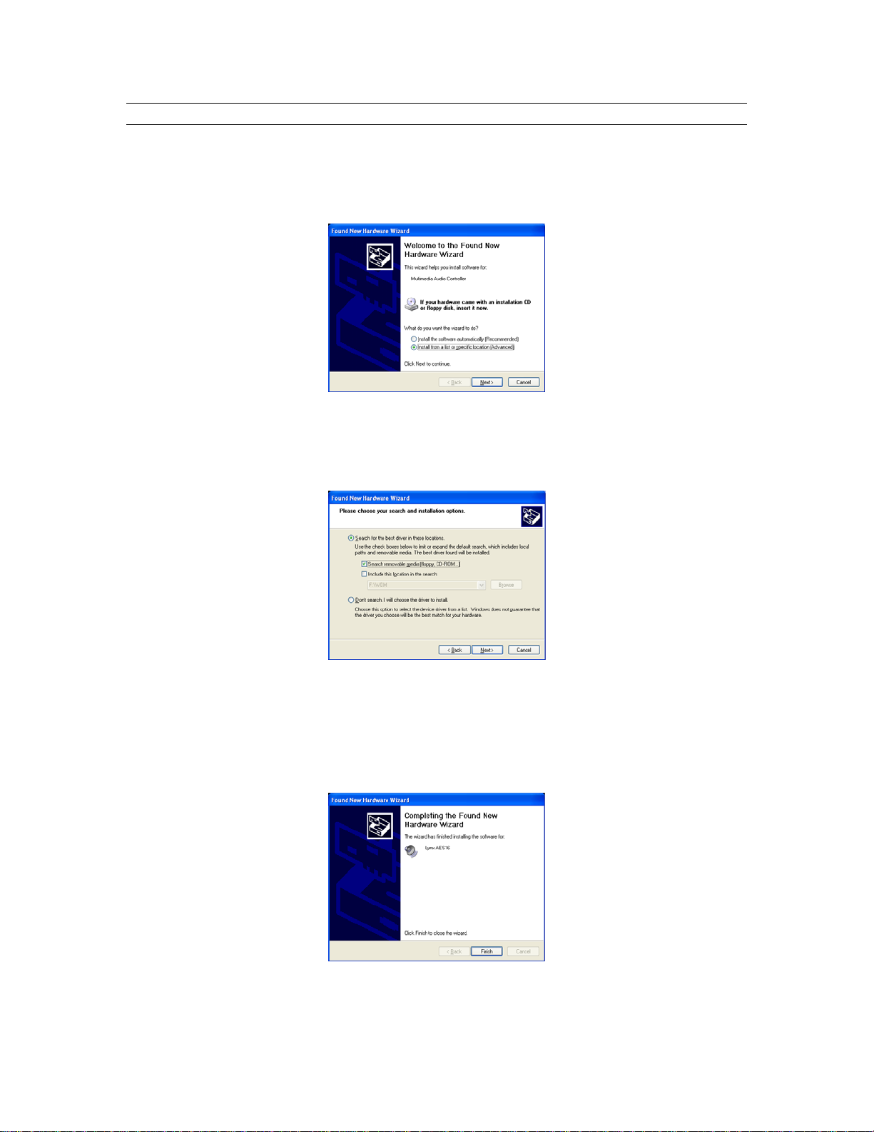
2.2.2 Installing the Windows Version 2 Driver Package
1. When you start Windows after installing the AES16 into your computer, the New Hardware
Wizard will appear. Select “Install from a list or specific location” and click “Next >” to proceed.
(NOTE: In Windows 2000, click “Next>” on the New Hardware Wizard welcome screen, on the
Install Hardware Device Driver dialog box, choose “Display a list of the known drivers for this
device” and click “Next>”)
2. From the next window, select "Search removable media”. Click "Next >" to proceed. (NOTE: In
Windows 2000 select “Sounds, video and game controllers” as a hardware type, and click
“Next>”. From the next screen click “Have Disk”, then type in the drive letter of your CD-ROM
drive, i.e. D:\, then click “OK”. Select the AES16 or AES16-SRC from the list of choices and
click “Next>”.)
3. Windows will begin to search for the appropriate driver files:
4. You may receive a warning that the driver has not been digitally signed by Microsoft. It is
perfectly safe to disregard this warning and select “Continue Anyway.” (NOTE: In Windows 2000
click “Yes” to continue installation.)
5. The driver installation will continue. After several moments, the new hardware wizard will
indicate that it has completed the installation. Click “Finish”:
6. Reboot the computer. The AES16 Card and Lynx Mixer application are now ready to use.
AES16 User Manual 9
Page 10
Installation Procedures
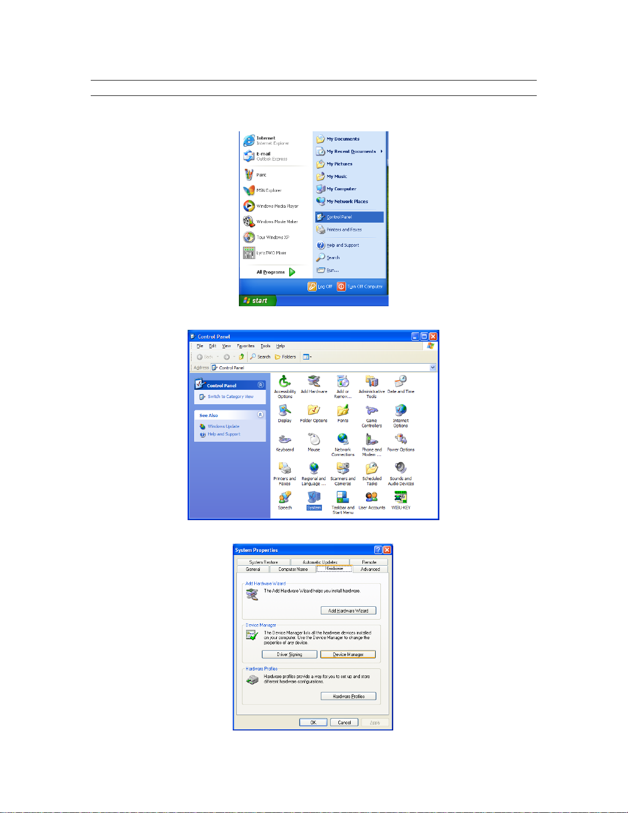
2.2.3 Uninstalling the AES16 Windows Version 2 Driver Package
1. From the start menu, click on “Control Panel.” (NOTE: In Windows 2000 click on Settings>
Control Panel.)
2. Click “System” to launch System Properties:
3. Choose “Device Manager” from the “Hardware” tab:
AES16 User Manual 10
Page 11
Installation Procedures
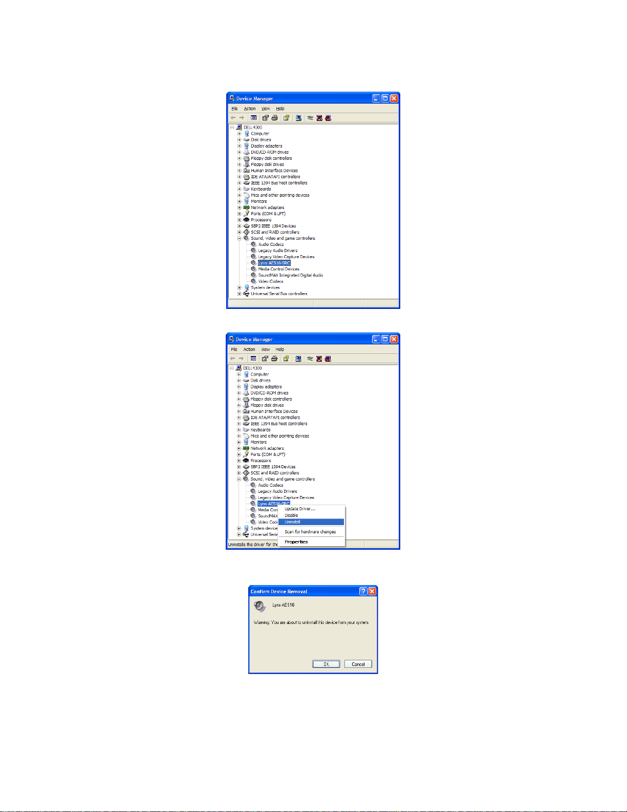
4. Expand the “Sound, video and game controllers” section of device manager be clicking its + sign:
5. Right click on “Lynx AES16” and choose “Uninstall”
6. Confirm device removal by clicking “OK”. (Note: In Windows 2000, click “Yes” when prompted
to restart your computer.)
7. Reboot the computer
AES16 User Manual 11
Page 12
Installation Procedures
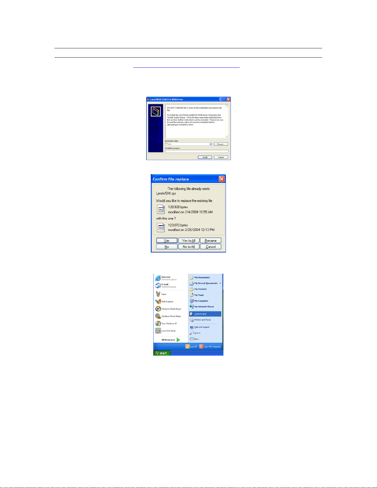
2.2.4 Updating an existing WDM driver:
Navigate your web browser to: http://www.lynxstudio.com/download.html. Scroll to the WDM driver
section and click on the appropriate file to download.
1. Double-click the downloaded file to decompress, and accept the default destination folder of
C:\Lynx.
2. Click “Yes to All” when prompted to confirm the files to be replaced.
3. From the start menu, click on “Control Panel.” (NOTE: In Windows 2000 click on “Settings >
Control Panel.”)
AES16 User Manual 12
Page 13

4. Click “System” to launch System Properties.
5. Choose “Device Manager” from the “Hardware” tab.
Installation Procedures
6. Expand the “Sound, video and game controllers” section of device manager be clicking its + sign.
AES16 User Manual 13
Page 14
Installation Procedures
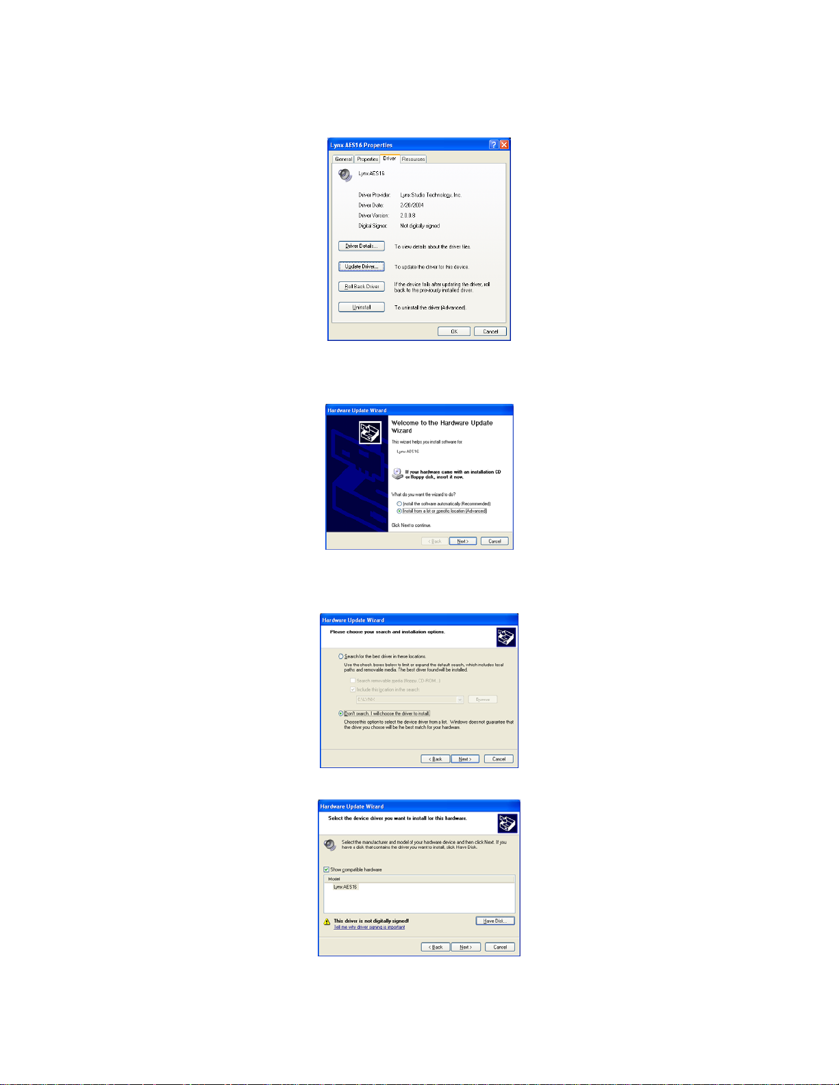
7. Double click the “LynxAES16” entry to launch the LynxAES16 Properties dialog box. Click the
“Driver” tab, then click “Update Driver…”.
8. When the Hardware Update Wizard box appears, choose “Install from a list or specific location
(Advanced)” and click “Next>.” (NOTE: In Windows 2000 click “Next>” on the Hardware
Upgrade Wizard welcome screen.)
9. From the next window, select "Don’t search, I will choose the driver to install”. Click "Next >" to
proceed. (NOTE: (In Windows 2000, choose “Display a list of the known drivers for this
device…” and click “Next>).
10. When prompted to select a device driver, click “Have Disk”.
AES16 User Manual 14
Page 15
Installation Procedures
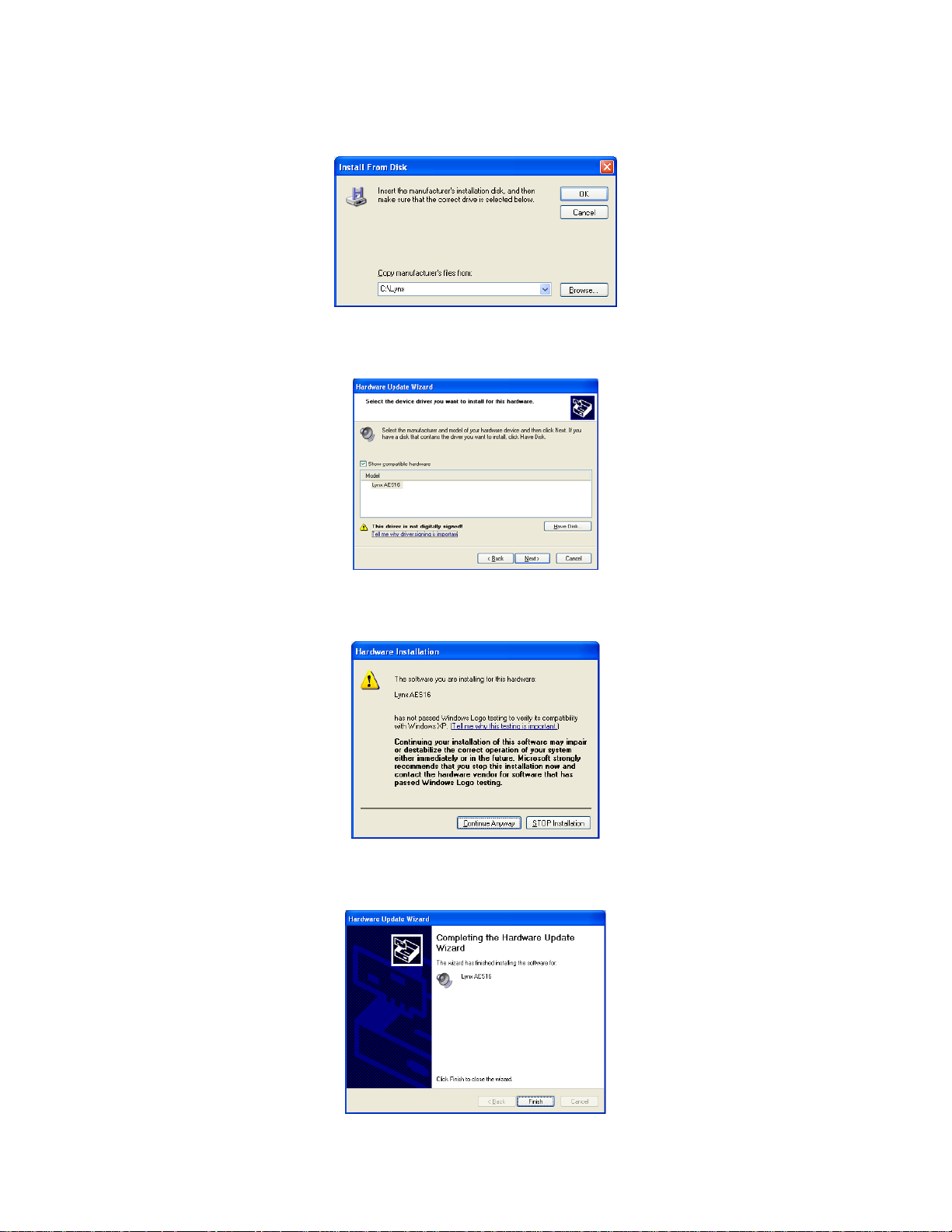
11. Next, you’ll be asked to insert the manufacturer’s installation disk into the drive selected (the
default is A:\) – type “C:\Lynx” in the text box, and click “OK”.
12. You will be prompted to select the device driver you are installing. “Lynx AES16” will be your
only choice. Select it and click “Next>”. (NOTE: In Windows 2000, choose AES16 from the list,
then click “Next>”. Click “Next>” on the subsequent confirmation window as well).
13. You may receive a warning that the driver has not been digitally signed by Microsoft. It is
perfectly safe to disregard this warning and click “Continue Anyway” to proceed with the
installation. (NOTE: In Windows 2000 click “Yes” to continue installation.)
14. The driver installation will continue. After several moments, the Hardware Update Wizard will
indicate that it has completed the installation. Click “Finish”. (NOTE: In Windows 2000 you will
be prompted to restart the computer. There is one remaining step, so choose “No.”)
AES16 User Manual 15
Page 16
Installation Procedures
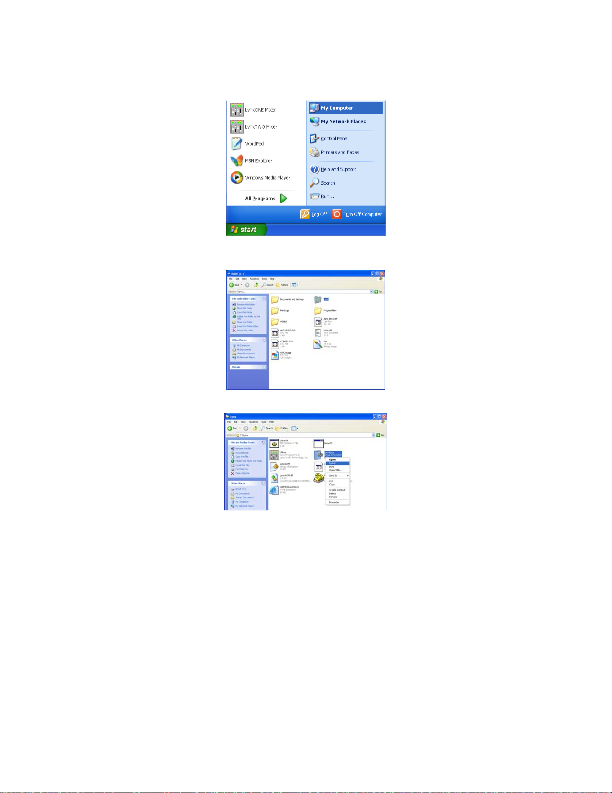
15. Next, we need to update the Lynx Mixer. From the Start Menu, choose “My Computer.” (NOTE:
In Windows 2000 click the “My Computer” icon on the desktop.)
16. Double-click on the C: Hard Drive and look for the “Lynx” Folder. Double Click the folder to
open it.
17. Right Click on the LynxApps file and click “Install”
18. The new Lynx Version 2 Driver Package is now ready to use.
AES16 User Manual 16
Page 17
Installation Procedures
2.3 Macintosh OS X
2.3.1 OS X Installation Files
The Lynx Installation CD contains all firmware and driver files mentioned in the subsequent installation
steps, as well as the AES16 mixer, manual, driver release notes and test files. If you do not have a
CDROM drive or need a more recent version, these files are available on our website at
http://www.lynxstudio.com.
2.3.2 Firmware Update
For Macintosh compatibility, the firmware stored in the on-board flash memory must be updated prior to
use. This is required because the AES16 ships from the factory with Windows firmware installed. To
update the firmware:
1. Locate the file L2Update_OSX.sit on the Lynx Installation CD and drag the file onto the computer
desktop, or download the latest OS X firmware file from
http://www.lynxstudio.com/download.html to the computer desktop.
2. Double-click on the L2Update_OSX.sit file to launch the Stuffit Expander. If a simple double-
click does not launch the Stuffit Expander, you may need to launch Stuffit Expander manually,
and then open the L2Update_OSX.sit file using the Open command in the File menu. Drag the
L2Update.app file to the desktop, which will decompress the firmware updater, and then close
Stuffit Expander. An L2Update program icon should now be on your desktop.
3. Make sure that no applications are open before running the firmware updater.
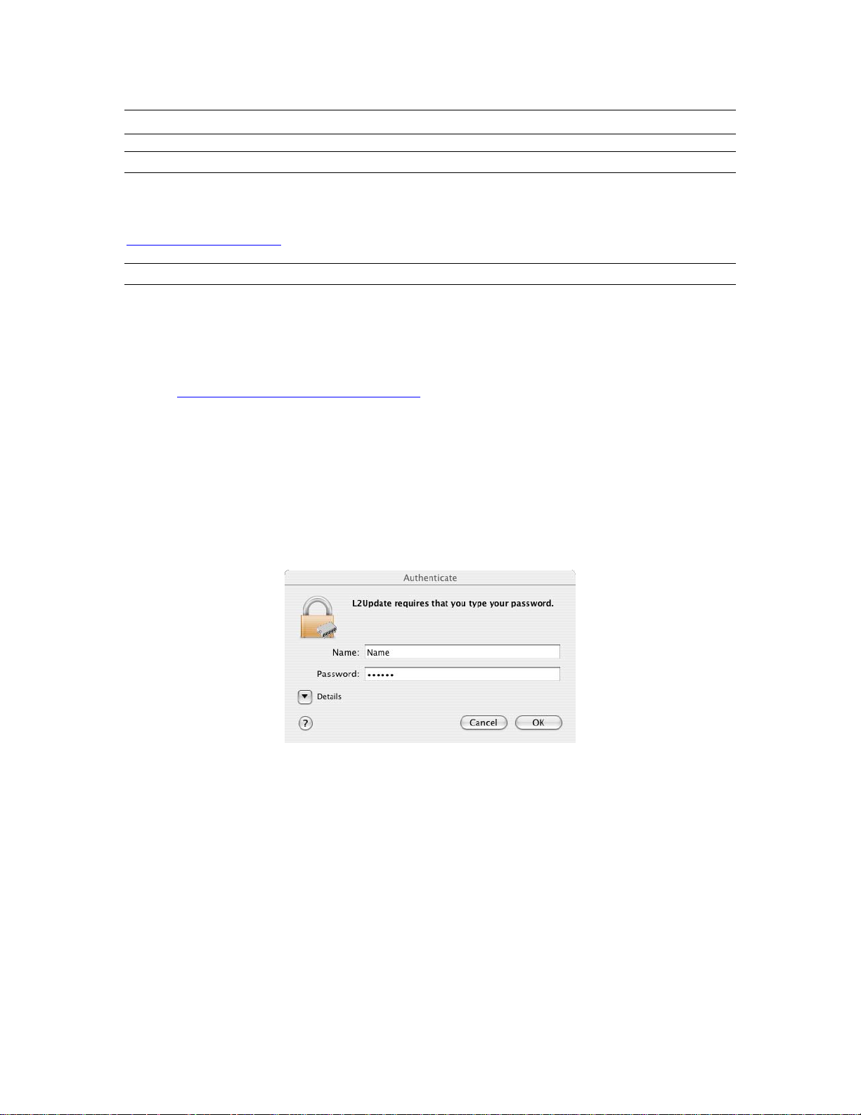
4. Run L2Update by double clicking on the L2Update program icon.
5. Enter your password in the Authenticate dialog box and click OK.
AES16 User Manual 17
Page 18
Installation Procedures
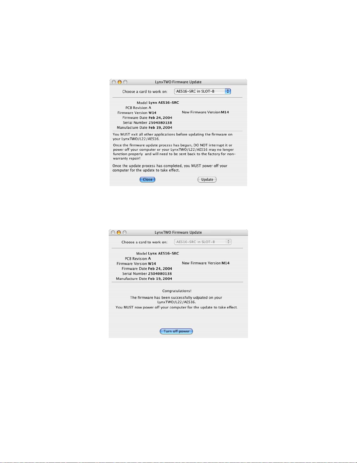
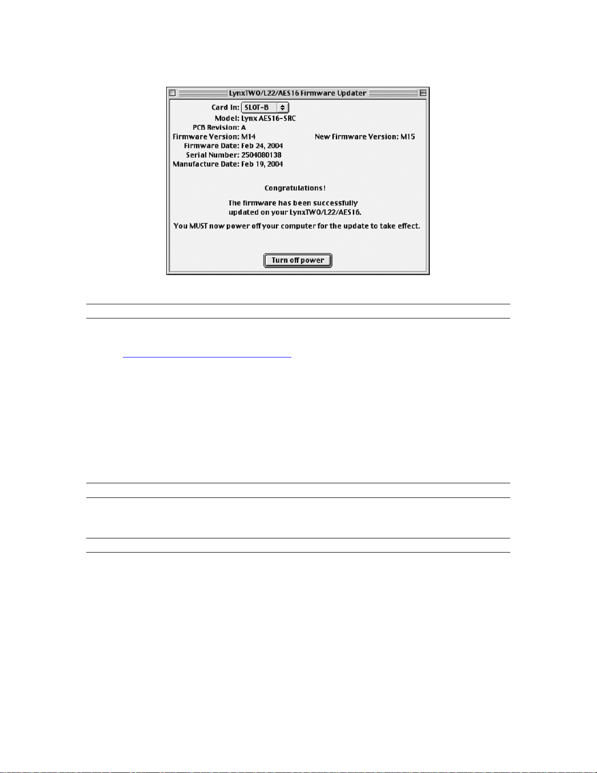
6. In a few moments, the “Lynx Two Firmware Update” dialog box should appear. Confirm that the
correct Lynx Card model appears under “Model” (please note: pictured below is the SRC version),
and also confirm that the Firmware Version and New Firmware Versions are NOT the sa m e.
While the number “14” is seen on both the Firmware Version and New Firmware Version, the
“W”:is for Windows and the “M” is for Macintosh.
7. Select “Update” and click OK when prompted to confirm the Update.
While the firmware updater is programming the on-board flash memory, it is
crucial that you do not power off the computer or interrupt the process in any way.
8. When the update is complete, you will be prompted to power off the computer.
9. After shutting down, wait for at least 10 seconds, then power the computer back on.
AES16 User Manual 18
Page 19
Installation Procedures
2.3.3 Install the AES16 Device Driver and Mixer
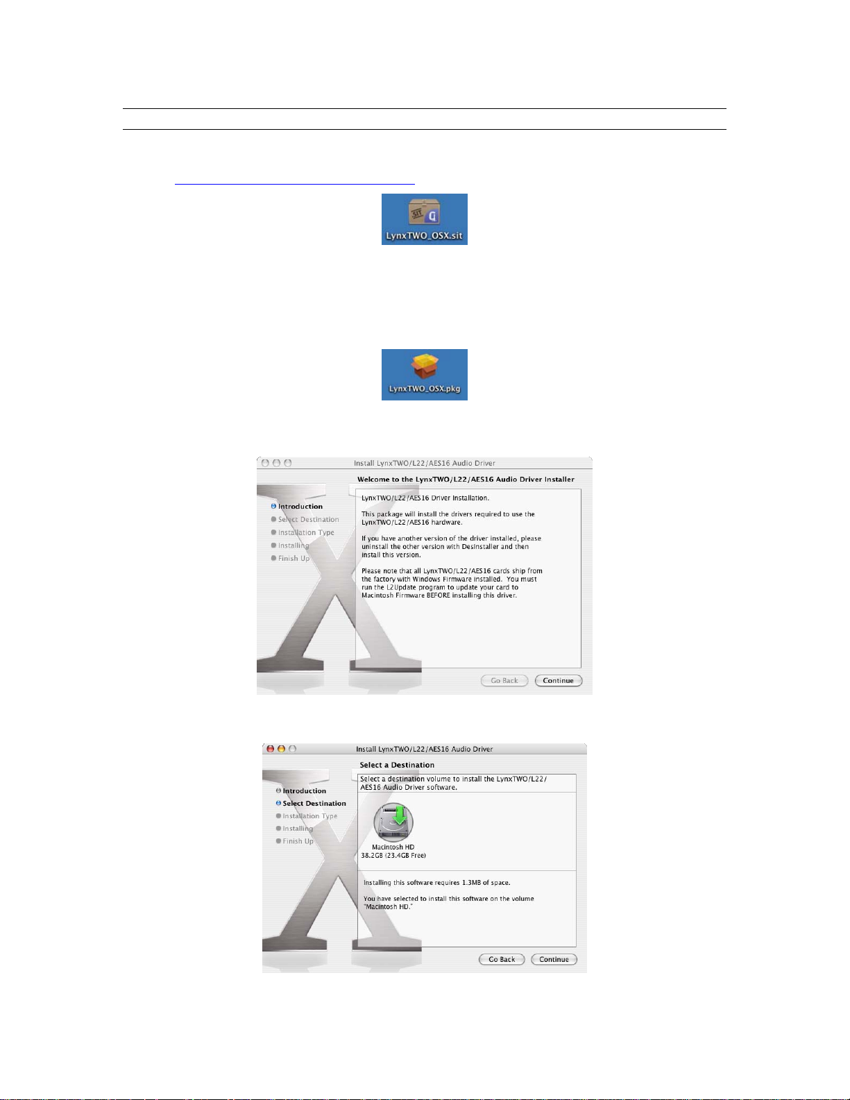
1. Locate the file LynxTWO_OSX.sit on the AES16 Installation CD and drag the file on to the
computer desktop, or download the late st OS X driver file from
http://www.lynxstudio.com/download.html to the computer desktop.
2. Double-click on the LynxTWO_OSX.sit file to launch the Stuffit Expander. If a simple double-
click does not launch the Stuffit Expander, you may need to launch Stuffit Expander manually,
and then open the LynxTWO_OSX.sit file using the Open command in the File menu.
3. Drag the LynxTWO_OSX.pkg file to the desktop, which will decompress the driver file, and then
close Stuffit Expander. A LynxTWO_OSX.pkg icon should now be on your desktop.
4. Double-click on the LynxTWO_OSX.pkg file. This will start the driver installation.
5. Click “Continue” at the “Install LynxTWO/L22/AES16 Audio Driver” dialog box.
6. When prompted to select a destination for the audio driver, click on “Macintosh HD” and then
click “Continue”.
AES16 User Manual 19
Page 20
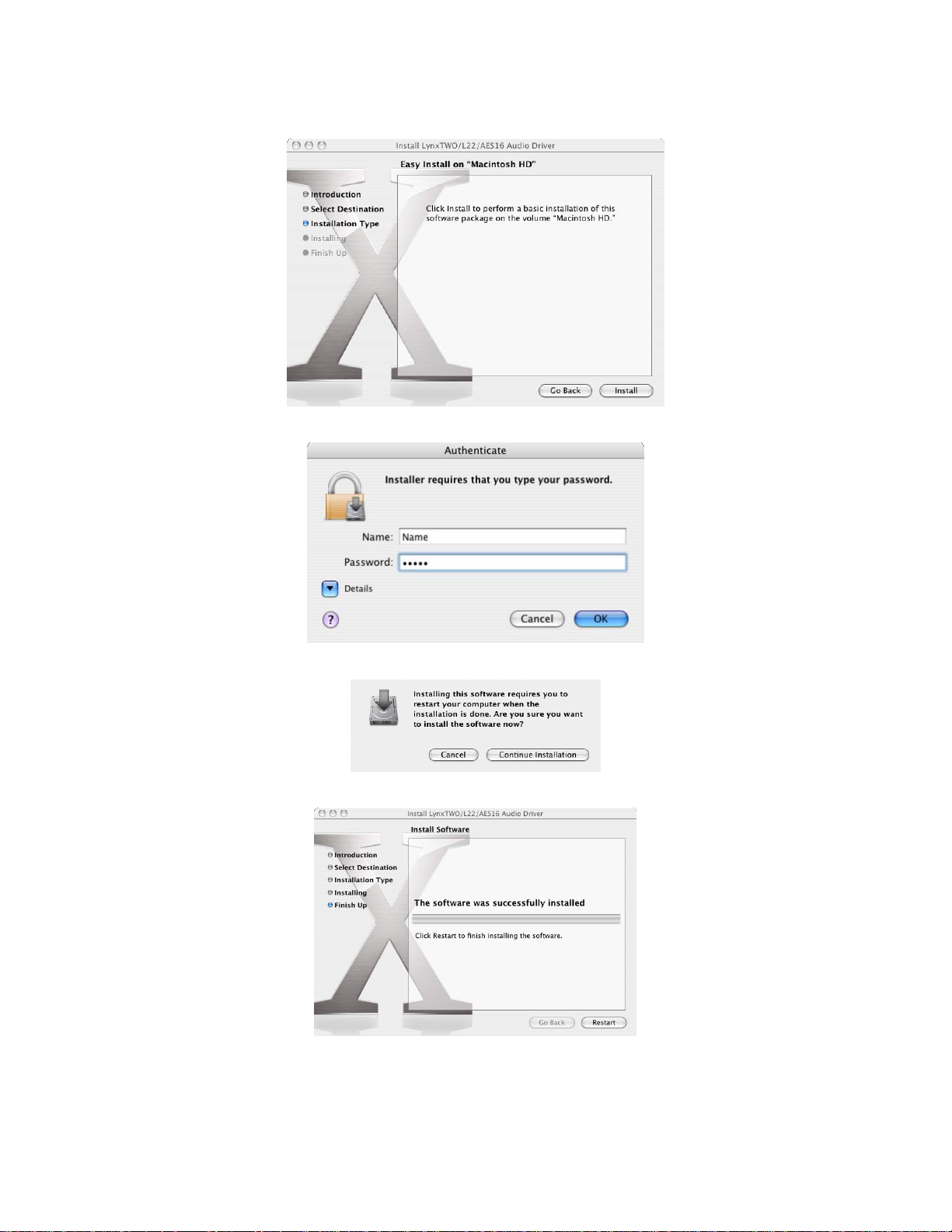
7. Click “Install” on the next dialog box that appears.
8. Enter your password in the Authenticate dialog box and click OK.
Installation Procedures
9. Click “Continue Installation” in the next dialog box that appears.
10. When the install is complete, you will be prompted to restart the computer.
NOTE: The OS X installation process installs both the Core Audio driver and the Lynx Mixer application.
The Lynx Mixer application is installed in the “Applications” folder.
AES16 User Manual 20
Page 21

Installation Procedures
2.3.4 Uninstalling the LynxTWO/L22/AES16 Device Driver and Mixer
To uninstall the driver, you will have to use a third-party uninstaller like DesInstaller, which you can get
http://www.macfixit.com/library/osxu.shtml. Follow the uninstaller’s instructions to remove the
from:
LynxTWO_OSX.pkg.
2.3.5 Updating the LynxTWO/L22/AES16 Device Driver and Mixer
To update the LynxTWO driver with a newer version, simply follow the instructions for uninstalling the
driver and then install the newer version per the installation instructions. You may need to reconfigure the
Lynx mixer and your recording application(s) after upda ting the driver.
AES16 User Manual 21
Page 22
Installation Procedures
2.4 Macintosh OS 9
2.4.1 Insert AES16 Installation CD in CD ROM Drive and Start Computer
The Installation CD contains all firmware and driver files mentioned in the subsequent installation steps, as
well as the AES16 manual, driver release notes and test files. If you do not have a CDROM drive or need a
more recent version, these files are available online at
2.4.2 Firmware Update
For Macintosh compatibility, the firmware stored in the on-board flash memory must be updated prior to
use. This is required because the AES16 ships from the factory with Windows firmware installed. To
update the firmware:
1. Locate the file L2Update_OS9.sit file on the AES16 Installation CD and drag the file onto the
computer desktop, or download the latest OS9 firmware file from
http://www.lynxstudio.com/download.html to the computer desktop.
2. Expand the firmware updater to the desktop using Aladdin Expander 5.0 or higher. An L2Update
program icon should now be on your desktop.
3. Make sure that no applications are open before running the firmware updater.
4. Run L2Update by double clicking on the L2Update program icon.
http://www.lynxstudio.com/download.html.
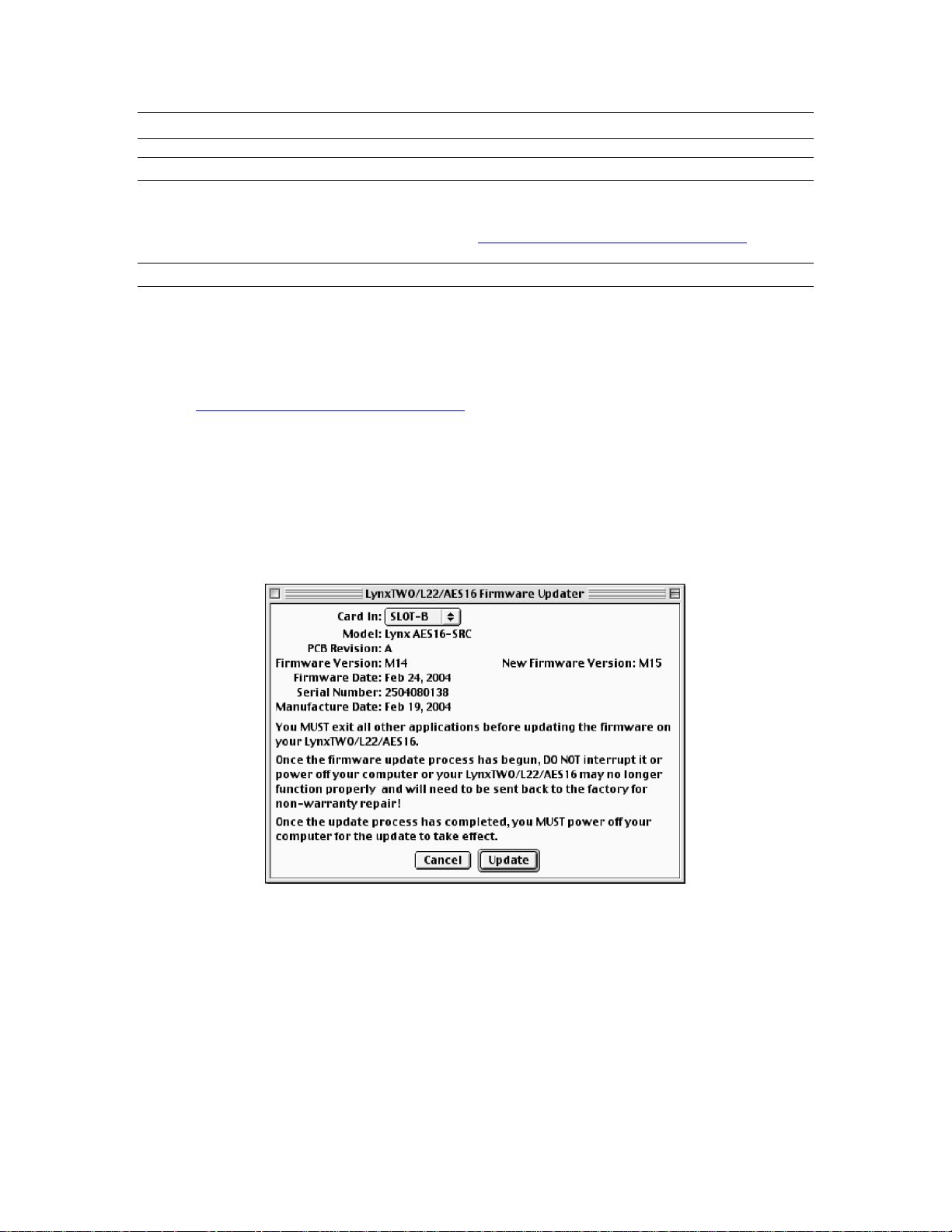
5. In a few moments, the “LynxTwo/L22/AES16 Firmware Updater” dialog box should appear .
Confirm that the correct Lynx Card model appears under “Model”, and also confirm that the
Firmware Version and New Firmware Versions are NOT the same.
6. Select “Update” and click “OK” when prompted to confirm the Update.
While the firmware updater is programming the on-board flash memory, it is
crucial that you do not power off the computer or interrupt the process in any way.
AES16 User Manual 22
Page 23
Installation Procedures
7. When the update is complete, you will be prompted to power off the computer.
8. After shutting down, wait for at least 10 seconds, and then power the computer back on.
2.4.3 Installing the OS9 ASIO Driver and Mixer
1. Locate the file LynxTWO_OS9.sit file on the AES16 Installation CD and drag the file onto the
computer desktop, or download the latest OS9 driver file from
http://www.lynxstudio.com/download.html to the computer desktop.
2. Expand the driver file to the desktop using Aladdin Expander 5.0 or higher. A “LynxTWO Mac
ASIO Driver” folder should now be on your desktop.
3. Open the LynxTWO Mac ASIO Driver folder and double click the “ASIO Drivers” folder to view
the “LynxTWO” file.
4. Locate the “ASIO Drivers” folder inside your audio application’s folder. Move the LynxTWO file
into this folder.
5. Launch your audio application and choose the ASIO driver “LynxTWO” within the program. You
can access the Lynx mixer program from within the ASIO control panel of your audio software.
2.4.4 Uninstalling the AES16 Device Driver and Mixer
To uninstall the driver, simply remove the LynxTWO file from the “ASIO Drivers” folder of your audio
application.
2.4.5 Updating the AES16 Device Driver and Mixer
To update the AES16 driver with a newer version, replace the existing LynxTWO file from the “ASIO
Drivers” folder of your audio application with the newer LynxTWO file.
AES16 User Manual 23
Page 24
Hardware Connections
3 Hardware Connections
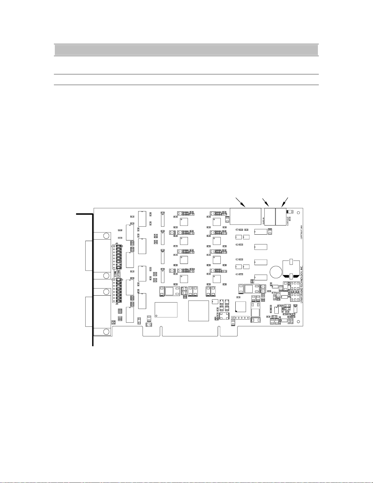
3.1 Overview
The AES16 includes eight AES/EBU compatible
inputs and outputs that provide sixteen channels
of digital audio I/O. These signals are available
on two bracket-mounted 26-pin high-density D
connectors, labeled I/O Port A and I/O Port B as
shown in Figure 1 below.
To accommodate a wide range of studio
equipment, the signal routing on each of these
ports can be configured using the I/O
Configuration jumpers to support either four
I/O PORT A
I/O Port A
inputs and four outputs or eight inputs or
outputs. Refer to Section 12.1 I/O Configuration
Jumpers for more information on how to set
these jumpers.
Also shown in Figure 1 are CLOCK IN and
CLOCK OUT connectors that provide word
clock I/O for internal synchronization with other
installed cards. The LStream Port provides a
connection for optional Lynx LStream expansion
cards.
Header
LStream
Port
Header
CLOCK IN
Port
LSTREAM
CLOCK OUT
Header
Port
A E S 1 6
I/O Port B
I/O PORT B
Figure 1: AES16 Board
AES16 User Manual 24
Page 25
Hardware Connections
3.2 AES/EBU Cable Connections
To minimize cabling issues, a variety of breakout cables are available for the AES16. The CBL-AES1604
cable, which is included with the AES16-XLR and AES16-SRC products, provides standard XLR
connectors. The CBL-AES1603 and CBL-AES1605 are optional cables that provide 25-pin D-Sub
connectors compatible with industry standard multi-channel digital equipment connectors. The following
table describes these cables and their application. As listed in th e table, the position of the I/O
Configuration Jumper must match the cable used. Refer to Section 12.1 I/O Configuration Jumpers for
more information.
Lynx Cable Connector type and signals Compatible Equipment I/O Jumper
Position
CBL-AES1603 Male DB25 for 8 AES in or out Apogee AD16, AD16X, DA16, DA16X 8 CHNL
CBL-AES1604 4 male XLR for AES out, 4 female
XLR for AES in, BNC for clock
CBL-AES1605 Male DB25 for 4 AES in and 4
AES out (standard Yamaha pinout)
Any device with standard AES/EBU XLR
connectors
All Yamaha equipment with DB25 digital
I/O including the following:
• Apogee Rosetta 800 and AD-8000
• TC Electronics DSP 6000
• Mackie HDR24/96 and D8B
4/4 CHNL
(default)
4/4 CHNL
(default)
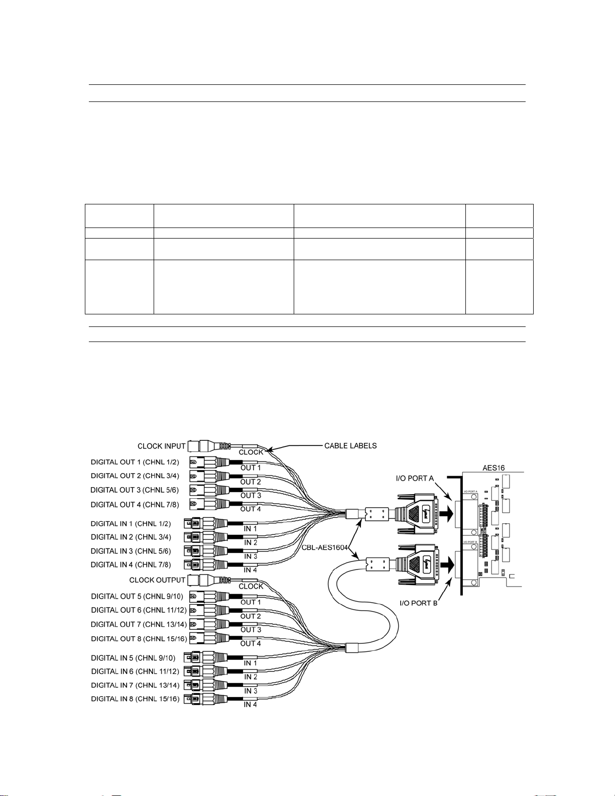
3.2.1 XLR Connections
The AES16-XLR and AES16-SRC include two CBL-AES1604 breakout cables with XLR connectors for
digital audio signals and female BNC connectors for clock input and output. Connect the cables to I/O
Ports A and B as shown in Figure 2 below. Tighten the thumbscrews on the cable shells for a secure
connection.
It is important to note that the signals associated with each XLR and BNC connector depend on which I/O
Port on is used. These signals are listed on the left side of the Figure 2.
Figure 2: XLR Connections with CBL-AES1604 Cable
AES16 User Manual 25
Page 26

Hardware Connections
3.2.2 Connections to Equipment with 25-Pin AES/EBU D-Sub Connectors
The CBL-AES1603 and CBL-AES1605 breakout cables are provide 25-pin D-sub connections for industry
standard equipment. Refer to the table in Section 3.2 AES/EBU Cable Connections for equipment
compatibility information.
Connect the 26-pin high-density connecter on each cable to I/O Ports A and B. Connect the 25-pin D-sub
connector on each cable to the external device. Tighten the thumbscrews on the cable shells for a secure
connection.
The signals associated with each 25-pin D-sub connector depend on which I/O Port on is used according to
the following table:
Lynx Cable Port Connected To Signals on 25-Pin D-sub
CBL-AES1603 I/O Port A DIGITAL IN 1-8
CBL-AES1603 I/O Port B DIGITAL OUT 1-8
CBL-AES1605 I/O Port A DIGITAL IN 1-4 and
DIGITAL OUT 1-4
CBL-AES1605 I/O Port B DIGITAL IN 5-8 and
DIGITAL 5-8
3.3 Clock Connections
In any system with more than one digital device, there can be only one master clock providing
synchronization. Whether you designate the AES16 as the clock master (slaving all other devices to it) or
slave the AES16 to another clock master, it is important that only a single device act as clock master, to
prevent the occurrence of audible digital errors.
The AES16 provides connections that allow for synchronization with external equipment or internal
devices within the computer.
3.3.1 External Clocking
Clock connections to external equipment are currently provided only with the CBL-AES1604 XLR
breakout cable. However, the AES16 can still be synchronized to external equipment using its AES/EBU
digital I/O.
With the CBL-AES1604 Cable connected to I/O Port A of the AES16, the BNC connector labeled
CLOCK acts a clock input. This input supports TTL signal levels and is terminated with 75 ohms of
impedance.
Connect this input to the clock output of an external device and select “External” as the Sample Clock
Source in the Lynx Mixer. Adjust the Sample Clock Reference to match the incoming clock type.
With the CBL-AES1604 Cable connected to I/O Port B of the AES16, the BNC connector labeled
CLOCK acts a word clock output. This output provides a 75-ohm TTL level signal at a frequency that
tracks the sample clock rate of the AES16. Connect this output to the word clock input of an external
device.
AES16 User Manual 26
Page 27

Hardware Connections
3.3.2 Internal Clocking and Multi-card Systems
Clock connections to internal equipment are provided via the header CLOCK IN and CLOCK OUT
connectors on the AES16 board. Refer to Figure 1 for the location of these connectors. The connectors
support 75-ohm, TTL level signals. If you are connecting to another Lynx digital audio card, the Lynx
Internal Clock Cable (CBL-ICC) or Universal Clock Cable (CBL-UCC) should be used.
Connect the CLOCK IN connector to the clock output of an internal device and select “Header” as the
clock source in the Lynx mixer. Adjust the clock Reference to match the incoming clock type.
The signal on the CLOCK OUT header is a word clock that tracks the sample rate of the AES16. Connect
this output to the word clock input of an internal device or another AES16.
As shown below in Figure 3, multiple AES16s can be synchronized using the optional Internal Clock
Cable. A daisy chain of CLOCK OUT to CLOCK IN is created so that all cards are tightly synchronized.
Refer to Section 9 Configuring Multiple AES16’s for more information.
Internal Clock Cable
AES16 Master
I/O PORT A
I/O PORT B
AES16 Slave 1
I/O PORT A
AES16 Slave 2
I/O PORT A
I/O PORT B
LSTREAM
LSTREAM
LSTREAM
AES16
I/O PORT B
Figure 3: Synchronizing Multiple AES16's Using Internal Clock Connections
Note: If an appropriate internal clock cable is not available, multiple cards can be synchronized externally
by using the BNC clock connections on the CBL-AES1604 cable. Use a standard 75-ohm BNC coaxial
patch cable to connect the input clock signals to the output clock signals.
AES16 User Manual 27
Page 28

Hardware Connections
3.4 Common Studio Setups
This section describes typical studio setups using the AES16.
3.4.1 External A/D and D/A with Word Clock
The figure below illustrates the connection of an eight-channel A/D converter and an eight-channel D/A
converter to I/O Port A of the AES16. This setup uses only half of the available I/O on the AES16.
Additional converters can be connected to I/O Port B to provide up to 16 channels of A/D and D/A
conversion.
Also shown is the use of the word clock output of the A/D as the system clock. This signal drives the word
clock input of the AES16, which is available on the CLOCK BNC connector on the breakout cable attached
to I/O Port A. Note: this connector is a word clock output when the cable is attached to I/O Port B. Also, a
separate word clock connection is not always required since any of the four AES inputs connected to I/O
Port A can be used as word clock sources.
I/O Configuration Jumper Settings
Confirm that the jumpers are set to the factory default 4/4 CHNL mode which accommodates the use of the
CBL-AES1604 XLR cable. See Section 12.1 I/O Configuration Jumpers for more informatio n.
AES16 Clock Settings
To select the external clock input as the sample clock source for the AES16, set the Sample Clock Source
in the Adapter window of the Lynx Mixer to External. Set the Reference to Word.
External Equipment Clock Settings
Since the internal clock of the A/D converter is the clock master in this setup, change its clock setting to
select its internal clock. Set the D/A converter to slave to one of its digital inputs. Alternatively, another
word clock signal from the A/D or from I/O Port B of the AES16 could drive the word clock input of the
D/A. In this case, the clock source of the D/A should be set to the appropriate setting for external word
clock.
AES16 User Manual 28
Page 29

Hardware Connections
3.4.2 Digital Mixer
The figure below illustrates the connection to a digital mixer that has 16 channels of AES/EBU digital I/O.
The D-Sub ports on the mixer must be compatible with the Yamaha multi-channel digital I/O standard.
Each of these ports provides eight channels of input and eight channels of output.
In this setup, either the digital mixer or AES16 can act as the system clock master depending on the clock
settings of each device. In each case, the clock is transmitted to the receiving device via the AES/EBU
connection.
I/O Configuration Jumper Settings
Confirm that the jumpers are set to the factory default 4/4 CHNL mode which accommodates the use of the
CBL-AES1605 XLR cable. See Section 12.1 I/O Configuration Jumpers for more informatio n.
AES16 and External Equipment Clock Settings
To use the digital mixer as the clock master: set the Sample Clock Source in the Adapter window of the
Lynx Mixer to Digital In 1. Set the Reference to Word. Change the clock source setting of the digital mixe r
to select its internal clock.
To use the AES16 as the clock master: set the Sample Clock Source in the Adapter window of the Lynx
Mixer to Internal. Change the clock source setting of the digital mixer to select one of its digital inputs.
AES16 User Manual 29
Page 30

Hardware Connections
3.4.3 Combined Use of XLR and DB25 Cable sets
The figure below illustrates a “mixed mode” configuration, where the AES16 is connected to an Apogee
AD16X 16-channel Analog-to-Digital converter and to some other 8-channel Digital-to-Analog converter.
This represents a unique situation, in that the AD16X will utilize all 16 available input channels while
connected to a single I/O port of the AES16, while only 8 output channels will be available to the D/A
converter.
The AD16X is connected to the AES16 via our CBL-AES1603 cable, which is specifically designed to
accommodate the Apogee 16-channel converters through their D-Sub port. I/O Port B in this example is
connected to an 8-channel D/A converter using our CBL-AES1604 cable with standard XLR connections.
It is critical that the AES/EBU inputs on the CBL-AES1604 cable NOT be connected to any external
device since these inputs are connected electrically to inputs on I/O Port A. Doing so will degrade the
quality of the digital signal received on I/O Port A. Consequently, this configuration is limited to 16
input channels and 8 output channels, rather than the 16 in and 16 out which are possible with other
cable set combinations.
PLEASE NOTE: Since the CBL-AES1605 supports input and output signals through a single connector, it
is not advisable to use the CBL-AES1605 with the CBL-AES1603 at the same time.
In this example, the AES16 will function as the system clock master, with the Apogee AD16X and 8channel D/A converter acting as clock slaves. As shown, the word clock output available on the BNC
connection of the CBL-AES1604 cable is connected to the word clock input on the Apogee AD16X. The
D/A converter can receive its clock via the AES/EBU signal from the AES16, or from the word clock out
of the AD16X. If the word clock is used, a connection from the AD16X word clock out to the D/A word
clock in is required.
I/O Configuration Jumper Settings
When using the CBL-AES1603 connected to an Apogee 16-channel converter, the associated I/O port on
the AES16 must be set to 8 CHNL mode. For this example, set the jumper for I/O Port A to 8 CHNL mode.
Confirm that the I/O Port B jumper is in the factory default 4/4 CHNL mode. See Section 12.1 I/O
Configuration Jumpers for more information.
AES16 User Manual 30
Page 31

Hardware Connections
AES16 Clock Settings
To setup the AES16 as the system clock master, set Sample Clock Source in the Lynx Mixer Adapter
window to Internal.
External Equipment Clock Settings
Change the clock setting on the AD16X to word clock in. This will force the AD16X to slave to the word
clock from the AES16. Change the clock setting on the D/A converter to select one of its AES/EBU inputs
as the clock source. Alternatively, if a word clock is connected to the D/A, set the clock source
appropriately.
Additional Setups with Apogee Converters
It is also possible for the AD16X to be the system clock master for the AES16 and D/A converter. Since the
CBL-AES1603 cable does not have a BNC connection for an external word clock input, the AES16 must
use one of its digital inputs to derive a clock source. In this case, the Sample Clock Source setting in the
Lynx Mixer Adapter window should be set to Digital In 1. The AD16X should be set to use its internal
clock, and the 8-channel D/A converter should be set to receive clock from one of its AES/EBU inputs, or
from word clock if the AD16X word clock output is connected to the D/A converter’s word clock input.
If 16 channels of D/A and 8 channels of A/D conversion are required, an Apogee DA16X can be used with
some other 8-channel Analog-to-Digital converter. In this case:
• Connect the DA16X and CBL-AES1603 to I/O Port B, and the A/D converter and CBL-AES1604 to
I/O Port A.
• Set the I/O Port B configuration jumper to 8CHNL mode. Set the I/O Port A jumper to 4/4 CHNL
mode.
• The XLR connectors representing outputs on the CBL-AES1604 cable must NOT be connected for
similar reasons as described above.
AES16 User Manual 31
Page 32

Getting Started
4 Getting Started
With the AES16 and its drivers properly installed in your computer, you can begin to use its capabilities
with most popular third party audio applications. In order for these applications to access the AES16 you
must select one of the AES16 audio devices in the application’s audio device configuration menu. Refer to
Section 8 Working with Third Party Applications for more information.
The following sections provide instructions for testing your installation.
4.1 Windows Quick Audio Test
The installation of your AES16 can be tested using the Lynx Mixer and the Lynx Demo application
included on the AES16 Installation CD. This is a quick way of verifying that the AES16 card is installed
correctly and properly connected to your external equipment.
1. Download the Demo32.exe application from
on the AES16 Installation CD that came with your AES16.
2. Locate “SineWaveMinus16.wav” on the AES16 Installation CD. Drag the file to the computer’s
desktop.
3. Connect the outputs of the AES16 to a digital destination (digital mixer, DA converters, etc.)
capable of delivering an audio signal for listening vi a head ph o nes or s pea kers. Depending on your
external equipment, you may be using the CBL-AES1603, CBL-AES1604 or CBL-AES1605
cables – please check Section 3 Hardware Connections of this manual for details on the proper
connection of these cables to your equipment. Verify that DIGITAL OUT 1 of the AES16 is
connected to your external equipment. This is the output used for this test.
4. Before testing playback, the clock relationship between the AES16 card and your external device
must be established. For this test, the AES16 acts as the clock master, while your external device
is the clock slave. Consult the manual for your connected equipment to determine how to set it to
receive sample clock from a digital input.
5. Most digital devices offer several choices for sample clock status, with “Internal” generally being
the default. If your device does not have the ability to receive its sample clock from a digital input,
please consult Section 3.4 Common Studio Setups for information on creating an alternate clock
relationship with the AES16. Keep in mind that the sample clock source of the AES16 is set to
“Internal” primarily to confirm the validity of your connections and installation – ultimately you
should create clock relationships that make the most sense for your specific situation.
6. Open the Lynx Mixer, which will be in the Lynx Studio Technology program directory (Start >
All Programs > Lynx Studio Technology > LynxTWO Mixer.)
http://www.lynxstudio.com/drivers, or locate this file
AES16 User Manual 32
Page 33

Getting Started
7. Choose “Restore Defaults” from the Mixer menu. This will insure that the sample clock source is
set to Internal, that the output levels are at maximum, and that no channels are muted.
8. Launch the Lynx Demo application by double-clicking the Demo32.exe file. The Lynx Demo
program should appear in the upper left corner of your screen. Make certain that the Play Device is
set to Lynx AES16 Play 1.
9. Click “File” and navigate to the computer’s Desktop, then select “SineWaveMinus16.wav” and
click “Open.”
10. Click “Play.” You should see the progress bar move from left to right.
AES16 User Manual 33
Page 34

Getting Started
11. Check the Lynx Output mixer and confirm meter activity for Digital Out 1L and Digital Out 1R. If
you have speakers or headphones connected to your destination device, you should hear audio as
well as seeing meter activity.
If the test did not operate as described or you received any errors, please refer to Section 10
Troubleshooting.
AES16 User Manual 34
Page 35

Getting Started
4.2 Macintosh OS X Quick Audio Test
The installation of your AES16 can be tested using the LynxTWO Mixer and the Demo version of Bias
Peak that was included on your AES16 Installation CD. This is a quick way of verifying that the AES16
card is installed correctly and is connected correctly to your extern al equipment.
1. Install the Bias Peak demo that is included on the AES16 installation CD, by clicking on the
peakTrial.sit file and following the installation instructions.
2. Locate “SineWaveMinus16.aif” on the AES16 Installation CD. Drag the file to the computer’s
desktop.
3. Connect the outputs of the AES16 to a digital destination (digital mixer, DA converters, etc.)
capable of delivering an audio signal for listening vi a head ph o nes or s pea kers. Depending on your
external gear, you may be using the CBL-AES1603, CBL-AES1604 or CBL-AES1605 cables please check Section 3 Hardware Connections for details on correctly connecting these cables to
your equipment. Verify that DIGITAL OUT 1 of the AES16 is connected to your external
equipment. This is the output used for this test.
4. Before testing playback, the clock relationship between the AES16 card and your external device
must be established. For this test, the AES16 acts as the clock master while your external device is
a clock slave. Consult the manual for your connected equipment to determine how to set it to
receive sample clock from a digital input. Most digital devices offer several choices for sample
clock status, with “Internal” generally being the default. If your device does not have the ability to
receive its sample clock from a digital input, please consult Section 3.4 Common Studio Setups
for information on creating an alternate clock relationship with the AES16. Keep in mind that the
sample clock source of the AES16 is set to “Internal” primarily to confirm the validity of your
connections and installation – ultimately you should create clock relationships that make the most
sense for your specific situation.
5. Open the LynxTWO Mixer, which will be in the OS X sidebar. Choose the “Adapter” tab, and
verify that the Sample Clock Source is set to “Internal”.
6. Launch the Peak Demo application by clicking the Peak 4 icon in the OS X sidebar, or use Finder
to launch Peak. Peak will prompt you to open an audio file. Choose “SineWaveMinus16.aif” on
the desktop and click “Open”.
AES16 User Manual 35
Page 36

Getting Started
7. In Peak, click “Audio Out” from the Audio menu. Verify that there is a check next to
“CoreAudio…”
8. Click “Hardware Settings…” from the Audio menu. Verify that the AES16 appears as the Output
device. Click “OK”.
9. Click “Play” from the Peak transport. You should see meter activity and the counter progressing.
10. Check the Lynx Output mixer and confirm meter activity for Digital Out 1L and Digital Out 1R. If
you have speakers or headphones connected to your destination device, you should also hear audio
and see meter activity.
If the test did not operate as described or you received any errors, please refer to Section 10
Troubleshooting.
AES16 User Manual 36
Page 37

Getting Started
4.3 Macintosh OS9 Quick Audio Test
The installation of your AES16 can be tested using the Demo version of Bias Peak that was included on
your AES16 Installation CD. This is a quick way of verifying that the AES16 card is installed correctly and
is connected correctly to your external equipment.
1. Install the Bias Peak demo that is included on the AES16 installation CD, by clicking on the
peakTrial.sit file and following the installation instructions.
2. Locate “SineWaveMinus16.aif” on the AES16 Installation CD. Drag the file to the computer’s
desktop.
3. Connect the outputs of the AES16 to a digital destination (digital mixer, DA converters, etc.)
capable of delivering an audio signal for listening vi a head ph o nes or s pea kers. Depending on your
external gear, you may be using the CBL-AES1603, CBL-AES1604 or CBL-AES1605 cables please check the Hardware Connections in this manual for details on correctly connecting these
cables to your equipment. Verify that DIGITAL OUT 1 of the AES16 is connected to your
external equipment. This is the output used for this test.
4. Before testing playback, the clock relationship between the AES16 card and your external device
must be established. For this test, the AES16 acts as the clock master while your external device is
a clock slave. Consult the manual for your connected equipment to determine how to set it to
receive sample clock from a digital input. Most digital devices offer several choices for sample
clock status, with “Internal” generally being the default. If your device does not have the ability to
receive its sample clock from a digital input, please consult Section 3.4 Common Studio Setups
for information on creating an alternate clock relationship with the AES16. Keep in mind that the
sample clock source of the AES16 is set to “Internal” primarily to confirm the validity of your
connections and installation – ultimately you should create clock relationships that make the most
sense for your specific situation.
5. Launch the Peak Demo application by clicking the Peak icon in the OS9 Applications Folder.
Peak will prompt you to open an audio file, choose “SineWaveMinus16.aif” on the desktop and
click “Open”.
• In Peak, click “Sound Out” from the Audio menu. Click “ASIO”.
AES16 User Manual 37
Page 38

Getting Started
6. Click “Hardware Settings…” from the Audio menu. This should launch the LynxTWO ASIO
Control Panel. Verify that the Sample Clock Source is set to “Internal”. Click “Close”.
7. Click the keyboard spacebar to begin playback of the “SineWaveMinus16.aif” audio file in Peak.
You should see the cursor scroll from left to right. If you have speakers or headphones connected
to your destination device, you should hear audio and see meter activity.
If the test did not operate as described or you received any errors, please refer to Section 10
Troubleshooting.
AES16 User Manual 38
Page 39

Operational Overview
5 Operational Overview
5.1 Signal Flow
As shown in the signal flow diagram below, the
AES16 with its on-board digital mixer provides
extensive signal routing capabilities that can
adapt to any studio requirement. The mixer is
implemented using a proprietary digital signal
processor (DSP) that is optimized to maintain
low latency and high signal quality.
AES16 Driver
Installed in Host
Computer
Stereo
Record
Devices
1 - 8
PCI
BUS
Record Bus
(16 Channels)
Digital Mixer Input Block
( 1 of 16 )
Peak
Level
Meter
MuteDither
Digital Mixer Ouput Submixer
( 1 of 16 )
Monitor
Select
Monitor
Select
Monitor
Stereo
Play
Devices
1 - 8
Play Bus
(16 Channels)
Select
Monitor
Select
Master
Fader
Figure 4: Signal Flow Diagram
Input
Patch
Sel e c t
SUM Dither
The architecture of the digital mixer consists of
16 record channels and 16 play channels that are
accessible to host applications as eight stereo
record devices and eight stereo play devices.
Submixers on each output provide low-latency
mixing for record monitoring and output mixing.
Input Bus (1..32)
(32 signals)
Output Bus
(16 signals )
Peak
Level
Meter
Input Bus 1,2
Input Bus 3,4
Input Bus 5,6
Input Bus 7,8
Input Bus 9,10
Input Bus 11,1 2
Input Bus 13,1 4
Input Bus 15,1 6
Input Bus 17..32
Output Bus 1,2
Output Bus 3,4
Output Bus 5, 6
Output Bus 7 ,8
Output Bus 9,10
Output Bus 11,12
Output Bus 13,1 4
Output Bus 15,1 6
Output Bus 1..8
Output Bus 9..16
SRC
SRC
SRC
SRC
1-8 / 9-16
Sel e c t
AES-3
RECV
AES-3
RECV
AES-3
RECV
AES-3
RECV
AES-3
RECV
AES-3
RECV
AES-3
RECV
AES-3
RECV
LStream
Receiver
AES-3
XMIT
AES-3
XMIT
AES-3
XMIT
AES-3
XMIT
AES-3
XMIT
AES-3
XMIT
AES-3
XMIT
AES-3
XMIT
LStream
Transmitter
IN 1
IN 2
IN 3
IN 4
IN 5
IN 6
IN 7
IN 8
LStream
Header P o rt
Input
OUT 1
OUT 2
OUT 3
OUT 4
OUT 5
OUT 6
OUT 7
OUT 8
LStream
Header Port
Output
AES16 User Manual 39
Page 40

5.1.1 Physical Inputs
Operational Overview
Starting from the digital inputs in the upper right
portion of Figure 4, each AES-3 input signal is
routed through a transformer for isolation before
arriving at an AES-3 receiver. The receiver
extracts a word clock, using a low jitter phaselocked loop, and signal data that is passed to the
Input Bus of digital mixer.
In the case of the SRC version of the AES16, the
signals on digital inputs 5 – 8 then pass through a
high-performance sample rate converter before
5.1.2 Digital Mixer Inputs
The digital mixer has 16 input blocks that
receive data from the Input Bus and drive the 16
channels of the record bus. Each of these blocks
has an input selector that allows selection of any
signal on the Input Bus. This selector allows
flexible patching of any AES16 physical input
signal to any of the 16 Record Bus channels.
After the selector, the signal passes through a
mute switch and then through the dither block,
which offers three popular dither algorithms and
bit-depth control. The output of the dither bl ock
merging with the Input Bus. This sample rate
converter can be enabled or disabled under user
control in the Lynx Mixer.
The LStream header on the AES16 is an
expansion port that provides an additional 16
inputs from a Lynx LStream device, such as the
LS-ADAT that offers 16 channels of ADAT
lightpipe. The signals from the LStream header
are routed through the LStream receiver, which
feeds the Input Bus.
is measured for peak level meters and feeds one
of the Record Bus channels.
Software control of the digital mixer’s input
blocks is provided in the Record/Play window of
the Lynx Mixer application. The input selector
corresponds to the Input Source select buttons
(above the faders for each record channel). Mute
and dither controls are also provided for each
channel on this window.
5.1.3 Record Bus and Devices
The 16 channels of the Record Bus are derived
from the outputs of the mixer input blocks.
These signals are routed to the host computer via
the PCI bus to the AES16 driver and also feed
the output section of the digital mixer to provide
zero latency record monitoring.
The AES driver installed on the host computer
assigns the 16 channels from the Record Bus to
eight stereo record devices as follows:
5.1.4 Play Bus and Devices
The Play Bus is derived from the 16 channels
sent to the AES16 play devices from host
applications. In other words, when an appl i cat i on
is used to playback a file, the data from the file is
sent to an AES16 play device. The AES16 driver
routes this data to the Play Bus, which feeds the
output section of the digital mixer. Similar to the
Record Bus, the 16 channels of the Play Bus
correspond to the AES16’s eight play devices are
follows:
Record Bus Channel 1 feeds the left channel
of Record Device 1
Record Bus Channel 2 feeds the right
channel Record Device 1
Record Bus Channel 3 feeds the left channel
Record Device 2
(etc)
(etc)
Record Bus Channel 16 feeds the right
channel Record Device 8
Left channel of Play Device 1 feeds Play
Bus Channel 1
Right channel of Play Device 1 feeds Play
Bus Channel 2
Left channel of Play Device 2 feeds Play
Bus Channel 3
(etc)
(etc)
Right channel of Play Device 8 feeds Play
Bus Channel 16
AES16 User Manual 40
Page 41

5.1.5 Digital Mixer Outputs
Operational Overview
The 16 output signals of the digital mixer are
derived from 16 four-input submixers. The
Record Bus and Play Bus feed the submixer
inputs, which each have an associated selector
(labeled Monitor Select in the diagram) and
volume control. The submixers use 40-bit
accumulators to maintain signal accuracy. The
output of the submixers are dithered to 24-bits
using triangular PDF dither and then measured
for peak level metering in the Lynx Mixer
application.
This architecture allows each digital mixer
output to be a mix of up to four signals derived
from any AES16 input or any play device
receiving data from a host application in
playback mode. The benefits of this architecture
include the ability to:
Route any input to any or all outputs
5.1.6 Physical Outputs
The physical outputs of the AES16 include eight
AES-3 signals and the output of the LStream
port. As shown in Figure 4, the 16 channels of
the Output Bus derived from the output
submixers feed the physical outputs. Since there
are 32 physical outputs (16 AES-3, 16 LStream)
and only 16 signals on the Output Bus, data sent
to the LStream output mimics data sent to the
AES-3 outputs.
Route any play device data from an
application to any or all outputs
Mix any input with any play device for
recording monitoring
Create sub mixes for digital effect sends
Since all mixing and routing is hardware-based,
so called “zero latency” is achieved.
Software control of the digital mixer outputs is
provided in the Outputs window of the Lynx
Mixer application. The Monitor Select function
in the diagram corresponds to the Output
Monitor Source buttons in the Mixer. The
volumes controls for the submixer inputs are
below these buttons. The master fader on the
Outputs window of the Mixer adjusts all of the
submixer input volumes. Mute and dither
controls are also provided for each channel on
this window. The dither button enables the
output TPDF dither.
An AES-3 transmitter followed by an isolation
transformer converts Output Bus signals to AES3 signals.
An LStream transmitter formats data for the
LStream output port. To provide more routing
flexibility the “1-8 / 9-16 Select” function shown
in the diagram allows routing of output signals to
a bank of eight LStream channels. Output Bus
signals 1-8 can be routed to LStream channels 916 if desired.
AES16 User Manual 41
Page 42

5.2 Sample Clock Generator
The AES16 utilizes a master sample clock
generator to derive all clocks related to the
digital audio sampling rate. As shown in Figure
5 below, the sample clock generator provides a
LOW-JITTER
CRYSTAL
OSCILLATOR
DIGITAL IN 1
WORD CLOCK
DIGITAL IN 2
WORD CLOCK
DIGITAL IN 3
WORD CLOCK
DIGITAL IN 4
WORD CLOCK
Figure 5: Sample Clock Generator
SAMPLE CLOCK
SOURCE SELECT
IN 1
IN 2
IN 3
IN 4
EXTERNAL
CLOCK IN
(BNC)
HEADER
CLOCK IN
LSTRE AM
PORT IN
AES-3
CLOCK
RECOVERY
AES-3
CLOCK
RECOVERY
AES-3
CLOCK
RECOVERY
AES-3
CLOCK
RECOVERY
Operational Overview
selection of various clocks sources ands both a
wide range and SynchroLock phase-lock loop
(PLL).
WIDE RANGE
ANALOG PLL
PLL
PLL
SYNCHROLOCK PLL
LOCKED
SELECT
CLOCK
CLOCK
DIVIDERS
SYSTEM
CLOCKS
5.2.1 Sample Clock Sources
The sample clock generator can derive its
reference clock from both an internal and various
external sources. Only one source can be
selected at any given time. User control of the
sample clock source selector is provided on the
Adapter window of the Lynx Mixer application.
The available clocks sources are:
5.2.2 Phase-lock Loops and Clock Dividers
A two-stage phase-lock loop system is used to
generate a high-frequency PLL Clock while
attenuating jitter in the selected sample clock
source. Refer to the Section 5.3 SynchroLock™
On-board low-jitter oscillator (Internal)
Digital In 1- 4: word clock recovered from
one of the first four AES-3 inputs
External Clock In: signal from the CLOCK
IN BNC connector on the CBL-AES1604
break-out cable
Header Clock In: signal from the board-
mounted header connector
LStream Port In: word clock from an
LStream device connected to the LStream
header port
for a description of the operation of the PLL’s.
Clock dividers derive required system clocks
from the PLL clock.
AES16 User Manual 42
Page 43

5.3 SynchroLock™
Operational Overview
The AES16 incorporates SynchroLock clock
synchronization technology to provide extreme
tolerance to noisy external AES/EBU and word
clock signals while generating an ultra-low jitter
clock. This technology is especially useful for
combating noise induced on cables in complex
studio installations. SynchroLock provides clock
synchronization while insuring bit-perfect digital
transmission. When the AES16 is connected in
an AES/EBU daisy chain, SynchroLock acts like
a jitter firewall to prevent the propagation of
jitter to downstream devices.
By coupling statistical analysis with low-noise
clock generation techniques, SynchroLock is
capable of attenuating jitter on incoming
AES/EBU signals by a factor of 3000:1.
Compare this to attenuation of 100:1 or less for
professional quality analog phase-lock loops
(PLL). SynchroLock can easily handle
AES/EBU signals with jitter levels in excess of
800 nanoseconds.
The SynchroLock sample clock is a two-stage
system that is comprised of a fast-locking, widerange analog PLL and digitally controlled
crystal-based secondary stage. Due to extensive
number crunching of the secondary stage,
SynchroLock typically requires one to two
minutes to achieve final lock. While the
secondary stage is working, the analog PLL loop
maintains lock, but with much less jitter
attenuation than the secondary stage.
When the final lock state is achieved, the
secondary stage is switched on line and becomes
the system clock source. In some cases this
switching process may cause a momentary
disruption in digital I/O. Because of this, it is
recommended that recording or playback not be
started until the green LOCK indicator in the
SynchroLock status window is observed. This
status window is located on the Adapter window
of the Lynx Mixer.
SynchroLock works on any external word clock
signal. By default, SynchroLock is active when
the Sample Clock source is set to a clock source
other than Internal.
When the clock source is set to “External,”
“Header,” or “LStream” the Reference must be
set to “Word.” SynchroLock can be disabled in
the settings menu of the mixer by clicking on
“Settings > Advanced > SynchroLock,” but this
is not recommended.
SynchroLock is capable of locking to word clock
frequencies within +/- 100ppm of 44.1 kHz, 48
kHz, 88.2kHz, 96 kHz, 176.4 kHz, or 192 kHz.
Signals that fall outside of the lock range will
cause the red RANGE indictor to appear in the
SynchroLock status window. In this case, the
analog PLL is active and will source the system
sample clock.
AES16 User Manual 43
Page 44

Lynx Mixer Reference
6 Lynx Mixer Reference
The Lynx Mixer, which is installed during setup,
provides software control of the features of the
AES16 and a visual indication of audio signal
level during recording and playback. It can be
6.1.1 Starting the Mixer
Windows: After installation, the Lynx Mixer icon, will appear on the Windows Quick Launch bar in the
lower portion of your screen.
By clicking on this icon, the Lynx Mixer will launch. If you do not have the Windows Quick Launch bar
activated, the Lynx Mixer can be started be selecting “Start > Programs > Lynx Studio Technology >
LynxTWO Mixer.”
Macintosh: In OS X, the Lynx Mixer can be launched by clicking the “LynxTWO Mixer” icon in the OS
X sidebar:
used dynamically to change operational settings
of the AES16, but in most cases once the settings
are configured for a particular studio installation
they require no further adjustment.
Or by clicking the LynxTWO Mixer in the Applications folder.
In OS9, you can access the Lynx Mixer by clicking the ASIO control panel from within your audio
application.
6.1.2 General Operation
If you are simply recording and playing digital audio without synchronizing to an external clock source,
you can begin using the AES16 by simply selecting the AES16 audio devices in your application software.
Typically, it is convenient to keep the Mixer running on your desktop to monitor signal levels or to allow
immediate access to Mixer controls requiring dynamic changes. The Mixer can be forced to appear on top
of other applications by selecting the “Always On Top” option in the Settings pull-down menu.
6.1.3 Mixer Configuration Recall
The state of the Mixer settings are saved each time your computer is shut down. The stored settings are
automatically recalled the next time your computer is restarted.
AES16 User Manual 44
Page 45

Lynx Mixer Reference
6.2 Adapter Window
q Sample Clock Section
This section of the mixer provides control of the system sample clock generator. All AES16 audio devices
on a single card MUST have identical sample rates since there is one on-board generator. Sample rates
cannot be changed while AES16 is playing or recording.
Source
This control selects the clock source that drives the sample clock
generator from the following options:
Internal Clock derived from the on-board crystal oscillator
External Clock signal from BNC CLOCK connector
Header Clock signal from the CLOCK IN header
LStream Clock signal from the LStream port
Digital In 1 Clock signal from the Digital 1 Input
Digital In 2 Clock signal from the Digital 2 Input
Digital In 3 Clock signal from the Digital 3 Input
Digital In 4 Clock signal from the Digital 4 Input
Reference
Provides selection of the clock source reference type. This control must be set match the type of clock
source selected as the sample clock source. The available choices are:
Auto Automatic selection; valid for Internal, Digital, and Video clock sources
13.5 MHz 13.5 MHz video dot clock; valid for External and Header clock sources
27 MHz 27 MHz video dot clock; valid for External and Header clock sources
Word Word clock; valid for External, Header, and LStream clock sources
Word256 256 times word clock; valid for External and Header clock sources
AES16 User Manual 45
Page 46

Lynx Mixer Reference
Rate
Displays the current sample rate of the AES16. When the AES16 is being used for recording or playback
by an application, the rate shown is the rate set by the application. Applications are always the “master” in
terms of setting the sample clock rate of the card.
The rate can also be adjusted manually using the adjacent pull down control. The rate will change only is
the card is idle (not recording and playing). Manual adjustments are not required if the card is being used
with an application.
WideWire In
Allows selection of AES/EBU dual-wire mode on ALL digital inputs for compatibility with legacy devices.
Dual-wire mode is enabled when the check box is checked; otherwise the inputs operate in single-wire
mode. Dual-wire mode is operational for sample rates greater than 50kHz. The number of available input
channels is reduced to eight when this mode is active. Refer to Section 7.5 AES/EBU Dual-wire operation
for more information.
WideWire Out
Allows selection of AES/EBU dual-wire mode on ALL digital output for compatibility with legacy devices.
Dual-wire mode is enabled when the check box is checked; otherwise the outputs operate in single-wire
mode. Dual-wire mode is operational for sample rates greater than 50kHz. The number of available output
channels is reduced to eight when this mode is active. Refer to Section 7.5 AES/EBU Dual-wire operation
for more information.
SynchroLock
Shows the status of SynchroLock clocking system.
SynchroLock is Lynx Studio Technology’s proprietary technology for attenuating jitter on clock inputs and
providing a stable clock for all digital signals passed through the AES16. The SynchroLock status window
and LED indicators show the current state of the SynchroLock system as described below. Prior to
achieving lock, the four green LED’s give an indication of the completion of various lock stages. During
this time the wide range analog PLL maintains lock. For more information on SynchroLock, refer to the
Section 5.3 SynchroLock™.
Working
: In this state SynchroLock is analyzing the input clock signal and making adjustments to
frequency and phase. This process typically takes two to three minutes to complete. The four LED’s show
progress towards final lock: One green LED denotes frequency lock to 3.2 ppm accuracy, two LED’s
denote frequency lock to 1.6 ppm accuracy, three LED’s denote frequency lock to 0.6 ppm and the
transition to the phase lock stage, four LED’s denote the start of the phase lock stage. When phase lock has
been achieved, the Yellow “Working” indicator changes to the green “Locked” indication.
Locked
: Indicates the SynchroLock system has achieved final lock to an incoming clock signal. This
indicator will also appear when the Sample Clock Source is set to Internal and the sample clock frequency
is a multiple of 44.1 kHz or 48 kHz.
: Indicates that the selected external clock source is not within the SynchroLock lock range.
Range
Disabled: Indicates that SynchroLock has been manually disabled using the SynchroLock control in the
Settings menu: Settings->Advanced->SynchroLock.
AES16 User Manual 46
Page 47

Lynx Mixer Reference
w System Clock Rates Section
This section of the Adapter Window displays real-time frequency measurements of system clocks. These
measurements are very useful for evaluating and validating both internal and external clock sources. When
synchronization or clocking issues are encountered, the user should refer to this information at the
beginning of troubleshooting. Note: the measured rates of the AES/EBU inputs are available in the Digital
Inputs section of the Adapter Window.
The sources of the system clocks begin measured are:
L/R Clock System sample clock generator word clock output
External External clock from CLOCK connection on I/O Port A
Header Clock signal from CLOCK IN header connector
LStream Clock signal from LStream port
PCI Computer’s PCI Bus speed (should always be about 33 MHz)
The Settings Menu offers a “High Resolution Clock Rate” option that provides three decimal places of
accuracy instead of the default single decimal place. With this option enabled, lower digits may fluctuate
rapidly as a result of measurement resolution. This is typically not an indication of clock jitter.
e Digital Input Status Section
This section displays status information pertaining to the AES16’s eight inputs. The data displayed
indicates the quality of the AES/EBU connections as well as channels status data sent by a transmitting
device. The information displayed in this section is very useful for troubleshooting digital input connection
issues. For more information about AES/EBU channel status data, refer to the AES-3 specification
available from the Audio Engineering Society web site at
Lock
Locked (green) Indicates the digital receiver is locked to a valid AES/EBU source
Unlocked (gray) Indicates the digital receiver is not locked to a valid AES/EBU source
When the Unlocked indicator is shown, all of the fields to the right will be blank.
Validity
Valid (green) Indicates the Valid channel status bit is set
Invalid (red) Indicates the Valid channel status bit is not set
The Valid bit is set by a transmitting device to indicate the validity of the audio data being transmitted. A
DAT machine for example may mark the data as invalid when it is not in play mode.
Parity
OK (green) Indicates accurate transmission of audio data
Error (red) Indicates an audio data error occurred during transmission
The parity bit is included in the AES/EBU data stream to validate the transmission of audio data. A parity
error indicates an audio data error was cased either by the transmitting device or the connecting cables.
http://www.aes.org.
CS CRC
OK (green) Indicates valid transmission of channel status data
AES16 User Manual 47
Page 48

Lynx Mixer Reference
Error (red) Indicates a transmission error in the channel status data
This indicator represents the state of Channel Status Cyclic Redundant Check used to validate the
transmission of the channel status data embedded in the AES stream. An error indicates a channel status
data error was caused either by the transmitting device or the connecting cables. Some devices do not
transmit CS CRC. In this case an error will be displayed, but the audio data can still be transmitted without
errors.
Type
This indicator represents the type of data stream being transmitted by the external device. The external
device indicates type using specific bits in the channel status data. Typically PCM types are shown with
green background and non-PCM types, such as Dolby AC3, have a yellow background.
Valid linear PCM types (bit width):
PCM PCM16 PCM18
PCM19 PCM20 PCM22
PCM23 PCM24
Valid compressed, non-PCM types:
Dolby AC-3
MPEG1L1 MPEG1L2 MPEG2
MPEG2AAC MPEG2L1 MPEG2L2
MPEG2L3 MPEG-4
DTS I DTS II DTS III
ATRAC ATRAC2/3
Emphasis
Off (gray) Emphasis is off
50/15us (green) 50/15us pre-emphasis
J17 (green) CCITTJ.17 emphasis
Unknown (green) Emphasis not indicated
The emphasis bit is part of the channel status data and is used by a transmitter to indicate if the audio data
being transmitted has been encoded with audio signal emphasis.
Rate
This indicator represents sample rate encoded in the channel status data.
Valid Rates include the following:
32.0; 44.1; 48.0; 88.2; 96.0; 176.4; 192.0 kHz (all in green) or Unknown (red)
Note: it is the responsibility of the transmitting device to send rate status that matches the actual rate of the
audio data stream being sent. However, it is possible for a rate discrepancy to exist during a valid
transmission.
Clock Rate
Clock Rate displays a real-time measurement of the sample rates of the incoming signals. These
measurements are very useful for evaluating and validating digital inputs when synchronization or clocking
issues are encountered.
AES16 User Manual 48
Page 49

Lynx Mixer Reference
The Settings Menu offers a “High Resolution Clock Rate” option that provides three decimal places of
accuracy instead of the default one decimal place. With this option enabled, lower digits may fluctuate
rapidly as a result of measurement resolution.
When WideWire In is checked to enable AES dual-wire operation on input, Clock Rate should read half of
the encoded channel status rate described above. For example, when running at 192 kHz with dual-wire
inputs, the Clock Rate should indicate 96.0 kHz and the LR Clock should indicate 192 kHz.
SRC Enable
This checkbox will only appear when using an AES16-SRC. This checkbox controls the state of the sample
rate converter for a specific digital input. When checked, the incoming signal is routed through the sample
rate converter so the sample rate will match the currently selected sample rate of the AES16-SRC. For
example, when the device connected to Digital In 5 is running at 48 kHz, the AES16-SRC is running at
44.1 kHz, and SRC Enable for Digital In 5 is ON, the AES16-SRC will convert the sample rate from 48
kHz to 44.1 kHz and the SRC Ratio (see below) will indicate approximately 0.918:1.
SRC Ratio
This indicator will only appear when using an AES16-SRC. Indicates Sample Rate Conversion Ratio when
the SRC Enable checkbox is turned on.
r Digital Outputs Control Section
This section provides control of status bits embedded in the AES/EBU stream for each digital output. For
more information about the use of these bits, refer to the AES-3 specification available from the Audio
Engineering Society web site at
Valid
This checkbox controls the state of the Valid bit. When checked, the Valid bit is turned on to indicate to the
receiving device that the audio data being transmitted is valid. This is the default state.
Non-PCM
This checkbox controls the state of the Non-PCM channel status bit. When checked, the Non-PCM bit is
turned on to indicate that audio data other than linear PCM (such as Dolby AC3 or DTS) is being
transmitted.
Emphasis
This checkbox controls the state of the emphasis channel status bits. When checked, the 50/15us emphasis
mode is indicated in the transmitted channel status.
http://www.aes.org.
AES16 User Manual 49
Page 50

6.3 Record/Play Window
Lynx Mixer Reference
t Input Source Select Buttons
These buttons control the patching of physical inputs to record device channels of the digital mixer. Each
device channel can derive its source from any one of the 32 available inputs, which include 16 from I/O
Port A and B and 16 from the LStream port. The button on the left side of each record device panel
corresponds to the left channel of the device.
Clicking on any of the Input Source Select buttons launches a pop-up menu displaying the available
sources that can be selected.
In this example, LStream In 1 is being routed to the left channel of record device 1. This
input would be valid if an LS-ADAT ADAT card was connected to the AES16’s LStream
Port.
y Peak Meter
These meters display the instantaneous peak level of audio being sent to the AES16 input selected by the
Input Source Select buttons.
AES16 User Manual 50
Page 51

Lynx Mixer Reference
u Mute
This button enables the mute function for the associated input.
i Dither
This button enables dithering for the associated input. The Record Dither Type control in the Settings menu
determines the type of dither applied to the input.
Dither is useful for improving signal fidelity when reducing the bit depth of incoming data from 24 bits to
20, 16, or 8 bits.
o Depth
This control sets the bit depth used for recording on each input. The options are 8 bit, 16 bit, 20 bit, 24 bit,
and Auto. When Auto is selected, the bit depth is set according to the sample format requested by an
application accessing the record device. For example, if the sample format is 16 Bit Stereo, the bit depth
will be set to 16 bit.
1) Record Dropout
This status indicator represents the number of audio dropouts that have occurred during recording on a
record device. Dropouts can produce audible glitches in audio files. They are typically caused by a
computer’s inability to process data from the AES16 fast enough. The indicator is reset at the start of
recording.
1! Record Sample Format
This status indicator represents the sample format of a recording device. The format, which is set by an
application accessing the device, determines the format of the data sent to the host computer for storage or
processing. The sample format indicates bit depth and mono or stereo mode. In the case of 32 bit formats,
the lower eight bits are set to zero.
1@ Record Device Label / Status Indicator
This label panel specifies the record device number associated with each input panel. When an application
is accessing a record device, the color of this label turns red to indicate the device is in record mode.
Observing this indicator can be very useful while debugging communication problems with third party
applications.
1# Play Dropout
This status indicator represents the number of audio dropouts that have occurred during playback on a play
device. Dropouts can produce audible glitches in audio files. They are typically caused by a computer’s
inability to send data to the AES16 fast enough. The indicator is reset at the start of playback.
AES16 User Manual 51
Page 52

Lynx Mixer Reference
1$ Play Sample Format
This status indicator represents the sample format of a play device. The format, which is set by an
application accessing the device, determines the format of the data sent from the host computer to the play
device. The sample format indicates bit depth and mono or stereo mode. In the case of 32 bit formats, the
lower eight bits are set to zero.
1% Play Device Label / Status Indicator
This label specifies a play device number associated with the Play Dropout and Play Sample Format
indicators described above. When an application is accessing a play device, the color of this label turns red
to indicate the device is in play mode. Observing this indicator can be very useful while debugging
communication problems with third party applications.
Please note play device information is unrelated to the record device controls contained in the same
vertical panel on the Record/Play Window. The location of this information was chosen in order to provide
a compact view of record and play device status.
AES16 User Manual 52
Page 53

6.4 Outputs Window
1^ Output Monitor Source Buttons
Lynx Mixer Reference
These buttons control the routing of record and playback sources that feed each of the 16 output channels.
Since each output is derived from the sum of the four sources, each button controls the selection of one of
the sources.
When a button is clicked, a pop-up menu is launched that displays the
available sources that can be selected. A Record submenu lists inputs a
their corresponding the record devices (which is dynamically upda
reflect Input Source selections in the Record/Play window). A Play
submenu lists the left and right channels of the eight play devices. The
No Source option disables a monitor source.
The example to the left shows Digital In 1 L being selected as one of the
four sources for OUT 1 L.
After a monitor source is selected, a four-character abbreviation of the
selection is placed on the button. For example, DI1L indicates Digital In
1 Left.
ted to
1^ Output Monitor Mute Buttons
The buttons, labeled M, located to the right of each Output Monitor Source Button control the muting of
the adjacent monitor source. When the button is “pushed in”, the mute function is enabled.
nd
1& Overload Indictor
This indicator represents the number of signal overloads that have occurred on an output. Overloads occur
when the summation of the four monitor sources feeding an output exceeds the full scale digital output
level.
AES16 User Manual 53
Page 54

Lynx Mixer Reference
1* Volume Faders
Theses faders provide digital attenuatio n of t he output signal prior to D/A conversion. With the volume
fader at its maximum position, the vertical line within the fader turns black, to indicate zero attenuation. In
this case the audio stream is unaltered. This is the recommended position for critical recording and
mixdown sessions in which the highest signal quality is required. When the volume fader is not at its
maximum or minimum position, the vertical line within the fader turns red to indicate that the volume
control is active.
1( Peak Meters
These meters display the instantaneous peak level of the output signal.
2) Mute
This button enables the mute function for the associated output.
2! Output Dither
This button enables the addition of triangular probability density dither for each associated output. Dither is
recommended for improving signal fidelity when more than one monitor source is driving an output or
when the volume fader is not at its maximum.
AES16 User Manual 54
Page 55

Lynx Mixer Reference
6.5 Mixer Menu
The Mixer menu, located at the top left of the screen, allows selection of global mixer functions.
2@ Restore Defaults
This option restores all user-selectable parameters to factory default settings. This feature should be used as
a first step when mixer settings issues are encountered.
2# Mixer Scene
This feature provides the ability to save and recall all user-selectable parameters. “Scenes” that contain the
state of all mixer settings can be saved to scene memory. Scenes may be recalled to quickly reconfigure the
mixer.
Scene memory is global to all users on a single computer and is initially empty. There is no limit to the
number of scenes that can be stored.
When the Mixer Scene option is selected, a dialog box will appear that lists stored scenes and allow entry
of new scenes. Restore, Save, and Delete buttons handle scene management as follows:
Restore
Restore button. The scene will be instantly recalled from memory and all mixer parameters will be
restored to the saved state.
Save
the Save button. The current mixer parameters will be stored into scene memory. Selecting an
existing scene name and clicking the Save button will overwrite that scene with the current
parameters.
Delete
click the Delete button. The Mixer Scene dialog box will remain open to allow further
editing/deleting of scenes.
NOTE: When the computer is shut down, the current mixer state is saved. When the computer is restarted,
the mixer state is restored. This function is independent of Mixer Scene operation.
– To restore a scene from memory, select the scene name from the list, and then click the
– To save a scene into memory, type the name of the scene into the Edit Window, then click
– To delete a previously saved scene from memory, select the scene name from the list and
AES16 User Manual 55
Page 56

2$ About Lynx Mixer
Lynx Mixer Reference
PLEASE NOTE: The About Lynx Mixer window will
display different information than what is shown here.
This option displays information about the Lynx Mixer, driver, and firmware as follows:
Mixer/Driver Version: Displays the current driver version and build number.
Build Date: Displays the date the driver and mixer were released.
Adapter Name: Displays the name of the Lynx audio adapter installed. Up to four Lynx audio
adapters may be shown.
Serial Number: Displays the serial number of the Lynx audio adapter installed.
PCB Revision: Displays the revision of the printed circuit board.
Firmware ID: Displays the firmware identification number (typically 0).
Firmware Revision: Displays the firmware revision.
Firmware Date: Displays the date the firmware was released.
2% Exit
This option closes the Lynx Mixer application.
AES16 User Manual 56
Page 57

Lynx Mixer Reference
6.6 Settings Menu
The Settings Menu offers access to advanced settings and an alternative method of accessing commonly
used functions that appear in the Adapter Window.
2^ Always on Top
When this option is checked, the Lynx Mixer window stays on top of other active windows.
2& High Resolution Clock Rates
When checked, this option enables the display of measured clock rates with 1-hertz resolution. Otherwise,
rates are displayed with 100-hertz resolution. This feature controls the display of all System Clock Rates
and the Digital Input Clock Rates on the Adapter Window of the mixer.
NOTE: With this option enabled, lower digits may fluctuate rapidly as a result of measurement resolution.
This is typically not an indication of clock jitter.
2* Level Meter Range
This option provides control of the range displayed by the peak meters on the Record/Play and Output
windows of the mixer. The available ranges are 70dB, 96dB, and 114dB (default). Decreasing the range
will increase the resolution of the meter display, which may be required for more critical monitoring. This
is a universal setting for all meters – it is not possible to set multiple ranges.
2( Sample Clock Source
This menu selection replicates the Sample Clock Source selection on the Adapter window (see Section 6.2
Adapter Window), for added conveni ence. In some situations it may be preferable to access this parameter
via this menu.
AES16 User Manual 57
Page 58

Lynx Mixer Reference
3) Sample Clock Reference
This menu selection replicates the Sample Clock Reference selection on the Adapter window (see Section
6.2 Adapter Window), for added convenience. In some situations it may be preferable to access this
parameter via this menu.
3! Record Dither Type
This option provides selection of the type of dither used on all record channels. The following options are
available:
None - Dither is disabled. Volume processing utilizes rounding prior to truncation.
Triangular - Enables the addition of triangular probability density dither. Triangular is the
preferred dither type in most cases.
Shaped Triangular - This type of dither is essentially high-pass filtered triangular dither that
places most of the dither energy at higher frequencies making it less audible to the human ear.
Shaped triangular dither decreases signal-to-noise by 4.8 dB
Rectangular - This type of dither decreases the signal-to-noise ratio by 3 dB (less than
triangular), but is less desirable because of its noise modulation effects.
In order to enable the selected dither type on a record channel, the Dither button on the assoc i ated channel
on the Record/Play window must be “pushed in”. See Section 6.3 Record/Play Window.
3@ Advanced
This option provides access to several advanced menu functions.
SRC Match Phase – This option will only
appear when using an AES16-SRC. When
checked, enables the SRC Match Phase mode to
ensure that all locked digital inputs using the
sample rate converter are in phase. Digital In 5
must have SRC Enabled to enable SRC Match
Phase mode.
SyncStart™ – When checked, enables the
SyncStart feature, which provides sample
accurate synchronization of multiple record and
SynchroLock™ – When checked, enables the
SynchroLock clock generator. This sho ul d be
disabled only when locking to external clocks
that are near the limit of the SynchroLock lock
range. Enabled by default.
playback devices. Enabled by default.
Mixer Lock – When checked, enables a locking
feature that prevents changes to any of the mixer
controls by any application, including the Lynx
Mixer.
AES16 User Manual 58
Page 59

Using the AES16
7 Using the AES16
This section describes how to perform common tasks with AES16. Additional information is available in
the Frequently Asked Questions (FAQ) section on the Lynx web site (
7.1 Mixer Scene Storage and Recall
Once you have configured the mixer’s routing and other parameters, you may save that configuration in
memory as a mixer “Scene.” Saved scenes may be recalled to quickly reconfigure the mixer.
When the computer is restarted after being shut down, the mixer will restart with its last-used
configuration. This function is independent of the Mixer Scene memory.
For more information on saving and recalling mixer scenes, refer to Section 6.5 Mixer Menu.
7.2 Input Patching
The physical inputs of the AES16 can be patched to any Record Bus channel of the on-board digital mixer.
This feature allows complete flexibility in routing inputs to tracks and record devices within software
applications.
As described in Section 5.1.2 Digital Mixer Inputs and shown below, the digital mixer has 16 input blocks,
each with an Input Patch Select switch. The Input Bus originates from the physical inputs. The Record Bus
feeds the record devices of the driver.
http://www.lynxstudio.com).
Digital Mixer Input Block
( 1 of 16 )
PCI
BUS
Recor d Bus
(16 Channels)
Peak
Level
Meter
Dit her
Mut e
Input
Patch
Sel ect
Input Bus (1..32)
(32 s ignals)
Access to the Input Patch Select switch is provided via the Input Source select buttons on the Record/Play
window of the Lynx Mixer.
By clicking on one of these buttons at the top of a mixer channel strip, you can select from any of the
available inputs and route the selected input to that record mixer channel.
Each mixer record channel can derive its source from any of the 32 physical inputs (16 AES-3 digital
inputs and 16 LStream port signals).
For more information on the Lynx Mixer input patching, refer to Section 6.3 Record/Play Window.
AES16 User Manual 59
Page 60

7.2.1 Monitoring Theory
Using the AES16
Low latency monitoring can be enabled using the
AES16’s on-board digital mixer. This method
avoids delays caused be monitoring through
application software. The digital mixer can be
setup manually using the Lynx Mixer application
or within applications that support direct
monitoring.
As discussed in Section 5.1.5 Digital Mixer
Outputs, each output of the AES16 is derived
from a four-input submixer. This submixer is
shown below. The inputs to the submixers
include both input signals and playback signals.
Enabling record monitoring is simply a matter of
selecting a desired input signal for mixing on a
particular output.
Digital Mixer Ouput Submixer
R
r
d
o
c
e
s
B
u
m
o
r
f
u
p
n
I
s
t
i
s
6
1
(
s
l
a
)
n
g
P
u
B
l
y
a
s
m
o
r
f
d
y
a
l
P
(
6
1
s
e
c
i
v
e
s
g
i
)
s
l
a
n
Monitor
Sel e ct
Monitor
Sel e ct
Monitor
Sel e ct
Monitor
Sel e ct
( 1 of 16 )
SUM
Master
Fader
Dither
Peak
Level
Meter
Output Bus
(16 signals)
7.2.2 Monitor Setup Using Lynx Mixer
The Outputs window of the Lynx Mixer provides access to the submixer connected to each physical output.
Controls on this window allow manual setup of monitoring.
The four Monitor Select blocks shown in the submixer diagram correspond to the four Output Monitor
Source buttons above the faders on each output channel of the Lynx Mixer. A mouse click on one of these
buttons launches a menu of Record and Playback sources. Selecting a Record source causes in input signal
to be routed to the output.
Horizontal faders below these buttons correspond to the submixer input volume controls,
the diagram above.
In this example, Digital In 1 is being selected as a monitor source for
Output 1 Left. The “M” button next to the Output Monitor So urce button
must be in the “out” position to unmute a monitor source. After the
source is selected, a corresponding four-letter pneumonic will appear on
the button.
, shown in
AES16 User Manual 60
Page 61

Using the AES16
7.2.3 Using Direct Monitoring in an ASIO Application
The Direct Monitoring (sometimes referred to as “hardware monitoring”) feature offered in many popular
third party applications provides a means to enable low-latency monitoring supported by the AES16’s onboard digital mixer. Instead of using the Lynx Mixer to manually enable monitoring as discussed in the
previous section, controls within the application provide convenient access to this functionality.
Additionally, some applications offer “tape type” monitoring whereby inputs are monitored only when
recording is taking place. When utilizing Direct Monitoring from a recording application, it is preferable to
NOT make alterations to the Lynx mixer directly, as these changes may cause Direct Monitoring to
produce unexpected results.
When Direct Monitoring is enabled in an application, Output Monitor Source
Buttons C and D are automatically assigned monitor sources.
Since panning of mono input sources is available with Direct
Monitoring, even though pan controls are not a feature of the Lynx
mixer, each mono source is assigned to both the left and right
channels of an output channel strip. When a mono signal is panned
from within the host application, the level sliders under each instance
of the monitor source will move accordingly. As an example: If
Digital In 1 Left is being monitored on Digital Out 1 Left & Right,
when you pan the input signal to the left the Monitor Source Volume
for Digital Out 1 Left increases and the Monitor Source Volume for
Digital Out 1 Right decreases.
Since this feature relies upon code within a third party application to operate, d ifferent software versions
may behave differently than described.
AES16 User Manual 61
Page 62

Using the AES16
Click the speaker icon in the Cubase 2/Nuendo 2 Mixer window to enable Direct
Monitoring.
Click the speaker icon in Samplitude/Sequoia to enable Direct Monitoring.
7.3 Playback Routing and Mixing
In addition to standard monitoring of inputs through physical outputs, the Lynx mixer is capable of
sophisticated routing and mixing of pl ay bac k a nd rec ord so urces. One can monitor playback from several
applications through a single output, combine live input and playback streams, and record a single source
into several applications with the power of this flexible tool.
In the Lynx Mixer Output Window, clicking one of the four Output Monitor
Source Buttons for each channel provides the opportunity to select a “Play”
source, which can be any of the 16 playback device channels available to the
system. For Digital Out 1 (Left and Right), the system default is to monitor Play1
(Left and Right), which appear as the monitor sources P1L and P1R. In this state,
any audio assigned to play out Play1 would be heard out of Digital Out 1.
AES16 User Manual 62
Page 63

Selecting Play 2 (P2L and P2R) in the next set of Monitor Source Buttons d
and un-muting this source, allows you to monitor audio from Play 1 and Play 2
out of Digital Out 1 at the same time. If one application or playback stream i
assigned to Play 1, and another to Play 2, you would hear audio from both out of
Digital Out 1. You can adjust the relative level of these two sources with the
volume slider directly underneath each Monitor Source Button.
Similarly, Record sources can be added so that up to four combinations of live
input, and pre-recorded playback can be routed and mixed to a single output. In
this way, headphone mixes, alternate house feeds, or a seamless blend of canned
and live broadcast material can be easily routed to appropriate outputs on the
AES16 card.
7.4 Clock selection and control
Using the AES16
own,
s
A valid clock source signal must be connected to
the appropriate AES16 clock connector when the
Sample Clock Source is set to “External,”
“Header,” or one of the Digital Inputs. If a signal
is not present, the sample clock generator will
run very slowly or erratically. Symptoms of this
problem include audio files that sound either
fast, slow or garbled.
The AES16 also includes a SynchroLock
clocking system to provide robust
synchronization to degraded input clock signals.
Refer to Section 5.3 for a detailed description of
SynchroLock.
When a valid clock source is present, the
frequency and type of clock signal must match
the Sample Clock Reference setting selected on
the Adapter window the Mixer. The frequency of
word clock sources, chosen by setting the
Sample Clock Source/Reference to
“External/Word,” “Header/Word,” or “Digital
In/Auto,” must match the sample rate specified
when recording new files, or the sample rate
associated with a previously recorded file during
playback.
For example, if a 44.1 kHz word clock is
connected to the external clock input, the Sample
Clock Source/Reference must be set to
“External/Word” and the sample rate must be set
to 44.1 kHz when a new file is being recorded in
an application. Failure to do so will result in files
being recorded at the wrong sample rate.
AES16 User Manual 63
Page 64

7.5 AES/EBU Dual-wire operation
Using the AES16
The AES16 supports dual-wire AES/EBU
operation in which each physical input or output
connection passes a single channel AES/EBU
signal running at half the system sample rate.
This capability provides compatibility with
legacy devices that do not support single-wire
AES running at sample rates greater than 50kHz.
Dual-wire mode can be enabled independently
for inputs and outputs using the WideWire In
and WideWire Out controls on the Adapter
window of the Lynx Mixer. See Section 6.2 for
more information. When dual-wire mode is
enabled the number of available audio channels
is reduced to eight.
With WideWire In enabled, the AES16 translates
dual-wire input signals internally to input
channels of the on-board mixer according to the
first table to the right. In this mode, input
channels 5 – 8 are not active.
NOTE: Mixer Input Channel selection is
available using the Input Source select buttons
on the Record/Play window of the Lynx Mixer.
See Section 6.3. Record/Play Window
With WideWire Out enabled, the AES16
translates output signals to dual-wire connections
according to the second table. In this mode,
output channels 5 – 8 are not active.
Input Connector Mixer Input Channel
IN 1 Digital In 1L
IN 2 Digital In 1R
IN 3 Digital In 2L
IN 4 Digital In 2R
IN 5 Digital In 3L
IN 6 Digital In 3R
IN 7 Digital In 4L
IN 8 Digital In 4R
Dual-wire Input Routing
Mixer Output
Channel
Digital Out 1L OUT 1
Digital Out 1R OUT 2
Digital Out 2L OUT 3
Digital Out 2R OUT 4
Digital Out 3L OUT 5
Digital Out 3R OUT 6
Digital Out 4L OUT 7
Digital Out 4R OUT 8
Dual-wire Output Routing
Input Connector
7.6 ASIO Specific Setup
Several control parameters of the AES16 are
accessible from the ASIO Control Panel within
applications that utilize the AES16 ASIO driver.
Specific controls may vary, but most
applications offer access to buffer size, clock
selection, sample rate and number of active I/O
channels. One of the benefits offered by this
inter-application control, is that these parameters
can be saved with a project – allowing consistent
performance conditions each time a project is
opened.
7.6.1 ASIO Positioning Protocol
The AES16 drivers support Steinberg's ASIO
Positioning Protocol (APP) for users that need
timecode synchronization capabilities and use an
application that supports ASIO Positioning
Protocol. In order to take advantage of this
feature, a Lynx LS-ADAT card would need to be
For this reason, it is preferable to initiate these
settings from within the ASIO application, rather
than from the Lynx Mixer Adapter window
whenever possible.
For specific information about the parameters
available from within the most popular audio
applications, please see the application notes on
our website, at:
http://www.lynxstudio.com/support.html
used in conjunction with the AES16 in order to
provide a sync source to the system. With a valid
sync source connected to the ADAT Sync In port
on the LS-ADAT, sample-accurate
synchronization is possible via APP.
AES16 User Manual 64
Page 65

7.7 Bus Mastering
Using the AES16
The AES16 hardware incorporates PCI Bus
Mastering, which greatly improves bus tra nsf er
efficiency without utilizing CPU cycles. With
this feature enabled, an application can typically
run with smaller buffers, which translates to
lower latency.
This feature is enabled by default in the driver. It
should only be disabled if absolutely necessary
in order to accommodate PCI bus conflicts with
other devices.
7.8 Controlling latency by changing buffer size
Latency in an audio interface can be defined as
the time required to process a sample requested
from an application to the interface’s audio
output. A number of factors determine the
achievable latency performance of a system
housing the AES16 card: processor speed,
operating system, sample rate, number of utilized
record or play channels, system efficiency, etc.
Latency can be manipulated by changing the size
of the buffers used to transfer data to and from
the AES16. When using an ASIO application
(i.e. Cubase, Samplitude, Sonar) the buffer
settings can be accessed via the application’s
ASIO control panel. Additionally, the AES16
Mixer Adapter window provides access to a
global buffer setting, which can define a single
buffer size available to WDM, ASIO and GSIF
applications.
The smaller the buffer size the lower the latency
will be. However, if a buffer size is too small for
the system or context, audio anomalies such as
clicks and pops can occur. One should become
familiar with altering the AES16 buffer size to
best suit their projects. Project sample rate is a
critical factor in determining an appropriate
buffer size. It is important to consider that as
sample rate increases, latency at the same buffer
size decreases. For instance, at a sample rate of
48 kHz, a buffer size of 128 samples will
produce a latency of 2.66ms. At 96 kHz, the
same buffer size would produce a latency value
of 1.55ms. Consequently, at the higher sample
rate, it is likely that you would need to increase
the buffer size to get the same performance.
7.9 Sample Rate Conversion
Information to be updated soon.
AES16 User Manual 65
Page 66

Working with Third Party Applications
8 Working with Third Party Applications
8.1 Compatibility
The drivers included with your AES16 provide
compatibility with all standard third party digital
audio applications that communicate with
Windows Wave audio, DirectSound, Audio
8.2 AES16 Devices
Third party applications communicate with the
AES16 through its installed driver. The driver
presents the AES16’s audio capabilities to
applications as standard multimedia,
DirectSound or ASIO devices. Most, if not all,
third party applications provide device selection
in configuration, options, or preference setting
windows or menus.
For two channel or stereo audio applications, a
separate selection option is typically provided for
the input or recording device and the output or
playback device. Multitrack applications provide
multiple input and output device selection menus
or windows. Refer to the documentation
included with your application to determine how
to select audio devices.
Units and ASIO devices. A list of applications
that have been tested for compatibility is
provided on the Lynx web site at
http://www.lynxstudio.com/swlist.html.
With the AES16 properly installed in your
computer, the digital audio devices will be
available to applications, and their names will
appear in their device selection menus as
follows:
AES16 Record 1 AES16 Play 1
AES16 Record 2 AES16 Play 2
AES16 Record 3 AES16 Play 3
AES16 Record 4 AES16 Play 4
AES16 Record 5 AES16 Play 5
AES16 Record 6 AES16 Play 6
AES16 Record 7 AES16 Play 7
AES16 Record 8 AES16 Play 8
When more than one AES16 is installed in your
system, the device names will contain a numeric
adapter ID assigned by the operating system. For
example, the analog output device on adapter 2
would be listed as “AES16 2 Record 1”. Refer to
the “Configuring Multiple AES16’s” section
below for more information.
AES16 User Manual 66
Page 67

8.3 Controlling Audio Bit Depth
Working with Third Party Applications
The creation of an audio file with a particular bit
depth (or resolution) is controlled through an
application’s recording settings. These settings
are typically adjusted in an audio device
configuration menu or in a recording setup
window just prior to recording. When recording
is initiated the AES16 will generate audio
samples of the desired resolution.
Bit depth control during playback of an audio
file is also an application issue. When a file is
played, the recorded bit depth is read from the
file’s header by the application. The application
8.4 Full Duplex Operation
The sixteen audio devices of the AES16 operate
completely independent in terms of whether they
are in recording or playback modes and their
associated audio files. This implies that the
devices can operate simultaneously and support
the so-called “full duplex” mode where, for
instance, the AES16 Record 1 device is
recording while the AES16 Play 1 device is
playing.
Although the devices act independently, when
multiple devices are being used to record or play
multiple audio files simultaneously, the AES16
uses this information to set the resolution of the
AES16.
The AES16 supports file types with 8, 16, 24, or
32 bit word widths. Note that 32-bit files contain
24-bit data with zero data in the least significant
bit positions.
The Lynx Mixer application displays the
currently selected bit depth for each device just
above the device name in the Record/Play
window.
driver has the capability to synchronously start
all devices with sample accuracy. This is
especially important for maintaining
synchronization during playback of multiple
devices and overdubbing.
By using all of the record and play devices,
sixteen-track recording and playback is possible.
Again, control of this multi-channel operation is
simply a matter of device selection in any
compatible multitrack audio application.
AES16 User Manual 67
Page 68

Configuring Multiple AES16’s
9 Configuring Multiple AES16’s
More than one AES16 card can be installed in a
computer for additional audio channels. If
required, all AES16’s in a computer can be
configured to maintain sample accurate
synchronization during digital audi o reco rding
and playback.
Cards are synchronized in a master-slave
arrangement. One card is selected as the master,
which provides the word clock source for the
other slave cards in the system. From the master,
the word clock signal is daisy-chained from one
slave to the next.
Word clock signals can be connected internally
using the CBL-ICC Internal Clock Cable, which
is available from Lynx. The CLOCK OUT
header of one card is connected to the CLOCK
IN header of the next card. A separate cable is
required for each slave card in the system.
Alternatively, the CLOCK connectors on the
CBL-AES1604 cables can be connected
externally with a standard 75 ohm BNC patch
cable.
9.1 Designating clock master and slaves
In order to select master and slave AES16’s in a
system, each adapter ID must be first physically
associated with a AES16 installed in a computer
slot. Windows 2000/XP or Macintosh OS
assigns the adapter IDs from the lowest slot
number to the highest slot number. The
procedure is as follows:
Connect at least OUT1 of each AES16 to
your external mixing console or other
equipment that will provide audio
monitoring.
Choose an audio application that allows
selection of wave audio devices for audio
playback.
Select “AES16 1 Play 1” as the playback
device.
Listen to the playback of any wave file and
note which AES16 card is generating the
Repeat steps 3 and 4, for “AES16 2 Play 1”,
The next step is to choose which AES16 will act
as a master. This choice is based on preference
only, but for ease of connection it makes sense to
choose an AES16 that is on one end of the PCI
slot array on your motherboard.
Alternatively, if clock connections are made
externally using the CLOCK connectors on the
CBL-AES1604 cables, use BNC cables to make
connections between cards in the same sequence
as described above
.
audio signal. In this case, the card
generating audio is adapter 1.
“AES16 3 Play 1”, and so on until all
AES16’s in your system have been
identified.
AES16 User Manual 68
Page 69

9.2 Adapter ID’s
Configuring Multiple AES16’s
When multiple AES16 cards are installed in a
computer they are automatically assigned unique
adapter ID numbers. These adapter ID’s provide
a means to identify and communicate with each
AES16 when using the Lynx Mixer application
and to select audio devices in third party
applications.
In the Lynx Mixer, the adapter that a user wishes
to control is selected from the “Window” pulldown menu. In a system with four AES16’s the
adapters will be listed as follows:
AES16 1 Mixer
AES16 2 Mixer
AES16 3 Mixer
AES16 4 Mixer
9.3 Cable connections
Starting with the master AES16, insert the plug
on one end of a Lynx Internal Clock Cable into
the CLOCK OUT header, until it clicks and
locks into place. This header is polarized to
ensure the correct orientation of the cable plug.
AES16 Master
I/O PORT A
AES16 Slave 1
I/O PORT A
AES16 Slave 2
I/O PORT B
I/O PORT A
I/O PORT B
In each case, the adapter ID is the numeric
character just before the word “Mixer” in each
selection.
Most third party applications provide a setup or
configuration menu for selecting a desired wave
audio device for recording and playback. With
multiple AES16’s in a system, each device name
will contain the adapter ID. For example, the
first play device on adapter 2 is listed as “AES16
2 Play 1”.
Insert the plug on the free end of the cable into
the CLOCK IN header, on the nearest slave
AES16. Connect each slave in a similar manner.
Refer to the figure below:
Internal Clock Cable
LSTREAM
LSTREAM
LSTREAM
AES16
I/O PORT B
AES16 User Manual 69
Page 70

9.4 Mixer settings
Configuring Multiple AES16’s
With the clock connections in place, the sample
clock settings of each AES16 must be adjusted
using the Lynx Mixer.
For the master AES16:
Select the master AES16 Adapter window of
the Lynx Mixer.
Select a desired Sample Clock Source.
Select a desired Sample Clock Reference.
For each slave AES16:
Select the master AES16 Adapter window of
the Lynx Mixer.
Set the Sample Clock Source to Header if
internal clock connections are used or
External if external clock connections are
used.
Set the Sample Clock Reference to Word.
AES16 User Manual 70
Page 71

Troubleshooting
10 Troubleshooting
Clicking, popping or crackling noises in your audio:
1. Check clock master settings. In any digital audio configuration, there can be one, and only one master
clock. All other digital audio devices must be configured as slaves to the designated master clock. Since the
AES16’s SynchroLock™ technology provides an extremely stable and jitter-resistant clock, we recommend
setting the AES16 as the master clock in your digital audio system.
2. Check buffer settings in your audio application software. Smaller buffer sizes are preferred because they
reduce latency (the time it takes for an audio signal to travel through your audio software). In some cases,
however, setting too small a buffer size can overtax your computer’s processor, particularly when running
multiple tracks and/or a number of DSP plug-ins. This can result in clicks and pops in your audio playback.
Try increasing the buffer size and see if your playback performance improves.
Audio plays back at a faster or slower rate than expected:
This is usually the result of mismatched clock rates and multiple clock masters. For example, if you are
playing back a file recorded at 44.1 kHz, but you have set the clock for 48 kHz, the file will play back
faster and at a higher pitch than expected. Make certain you have set only one device as clock master.
No audio:
If you see signal appearing on the AES16’s output meters, verify your output connections, making certain
you have a valid signal flow from the AES16’s outputs to your mixer or other D/A device, and from that
device to your speakers.
If you see no signal appearing on the AES16’s input meters, verify your connections, making certain you
have valid signal flow from your digital audio source to the AES16’s inputs.
AES16 User Manual 71
Page 72

Support
11 Support
We are devoted to making your experience with
AES16 trouble-free and productive. If you have
questions or comments regarding the operation
of your AES16 please check the
“Troubleshooting” section of this manual and the
11.1 Contact us
FAQ and Troubleshooting topics on the Support
section of the Lynx web site at:
http://www.lynxstudio.com/support.html
If you are unable to find information about your
problem please send us a support request by
filling out the form at:
http://www.lynxstudio.com/supportrequest.html
In your email message include the following
information:
• The serial number of your AES16.
• Which operating system you are using.
• The type of computer you are using.
• The name of the application you are using.
11.2 Registering your AES16
Lynx is committed to providing you with the
best service possible. To help us serve you
better, please be sure to register your AES16
using one of the following methods:
Fill out and mail the Warranty Registration
Card included with your AES16.
Use the Online Registration Wizard. To start
the wizard, click on Start > Programs >
Lynx Studio Technology > Online
Registration Wizard.
• A detailed description of the problem including
any error messages you received.
We will provide a response in a timely manner.
Telephone support is available by calling (949)
515-8265 ext 206 from 9AM to 5PM Pacific
Time, Monday through Friday, excluding United
States Holidays. Please be sure to have the above
information available before calling.
If you do not have an internet connection on
the computer you into which you installed
your AES16, simply copy the
REGISTER.EXE program from the
C:\Program Files\Lynx Studio Technology
folder to a computer with an intern et
connection and run REGISTER.EXE from
there.
Register on the web at:
http://www.lynxstudio.com/support.html
Once you are registered you will automatically
receive notifications of new products and
upgrades.
11.3 Locating the Serial Number of Your AES16
To register your AES16, you must supply its serial number. The serial number is located on a label attached
to the back of the card, and on the shipping carton.
You can also determine the serial number of your card by selecting About Mixer in the Mixer menu of the
Lynx Mixer.
When registering with the Online Registration Wizard, the serial number will be automatically entered.
AES16 User Manual 72
Page 73

Appendices
12 Appendices
12.1 I/O Configuration Jumpers
I/O Port A and I/O Port B can be configured to
support two different I/O routing modes. The
routing mode is selected by the position of two
8-position I/O Configuration Jumpers on headers
I/O PORT A
I/O Port A
I/O Port B
I/O PORT B
JP5 and JP6. The mode selected must be
compatible with the AES16 breakout cable being
used.
Header
LStream
Port
Header
CLOCK IN
Port
LSTREAM
Header
CLOCK OUT
Port
A E S 1 6
I/O Configuration Jumpers JP5 and JP6
For connections to equipment with D25 connectors supporting four
AES/EBU inputs and outputs, both of the I/O Configuration Jumpers
should be set to the 4/4 CHNL position on JP5 and JP6 as shown at
left. This is the factory default position and is the position required for
the CBL-AES1604 and CBL-AES1605 cables.
AES16 User Manual 73
Page 74

Appendices
For connections to equipment with D25 connectors supporting
eight channels of input or eight channels of output, the I/O
Configuration Jumpers should be set to the 8 CHNL position on
JP5 and JP6 as shown below. In this position, I/O Port A provides
eight AES/EBU inputs and I/O Port B provides eight AES/EBU
outputs. This is the required position for CBL-AES1603.
In either I/O Configuration mode, a clock input signal is available on I/O Port A and a clock output signal
is available on I/O Port B. These signals are available on the BNC connectors on CBL-AES1604 breakout
cable
AES16 User Manual 74
Page 75

12.2 Specifications
DIGITAL I/O
Number / Type
Channels
Sample Rates
Sample Rate
Conversion
ARCHITECTURE
Core
Audio Devices
CLOCKING
Sources
SynchroLock
ON-BOARD DIGITAL MIXER
Type
Routing
Mixing
Status
LSTREAM EXPANSION PORT
Compatibility
Type
CONNECTIONS
I/O Ports
External Clock
Internal Clock
SOFTWARE
Windows Drivers
Macintosh
Drivers
Mixer
Application
GENERAL
PCI Bus
Data Transfers
Size
Appendices
Eight inputs and eight outputs,
24-bit AES/EBU format, transformer coupled
16 in/out in single-wire mode, 8 in/out in dual-wire mode
All standard rates and variable rates up to 192 kHz in both si ngl e wi re an d
dual-wire modes
Eight channels available with support for conversion ratios up to 16:1.
Dynamic range: 142 dB. Multiple-input SRC phase matching. AES16-SRC
model only.
FPGA-based core contains custom PCI interface, data routing and
formatting, device/stream control, digital mixing, clock routing and control,
and DMA engine. 256 Kbytes of on-board RAM for data buffer ing.
Support for field upgrades of firmware.
Card is visible to host applications as eight record devices and eight play
devices. Each device has two channels and can be used independently for
multi-client functionality.
Digital inputs 1 – 4, external word clock (XLR model only) on BNC, internal
word clock on header, on-board low-jitter crystal oscillator
Multi-stage, VCXO-based clock generation system with high jitter
attenuation. Wide mode tracks off-frequency clocks, narrow mode generates
ultra-low jitter output for standard frequencies.
Hardware-based, low-latency
Ability to route any input to any or multiple outputs
Up to four input or playback signals mixed to any output, 40-bit precision
Peak levels to -114 dB on all inputs and outputs.
Supports Lynx LStream expansion cards including the LS-ADAT 16Channel ADAT I/O card
High-speed serial, up to 16 channels @ 24-bits. 14-pin internal connector.
Two bracket-mounted 26-pin high-density female D-sub connectors. Can be
configured to support eight channel or four channel AES connections.
75-ohm BNC word clock input and output provided on XLR breakout cables
Two 75-ohm board mounted 2-pin headers for word clock input and output
Windows 2000 / XP platforms: MME, ASIO 2.0, WDM, and DirectSound
ASIO 2.0 for OS9 and Core Audio for OS X
Multi-window GUI provides complete control of digital mixer and all
hardware settings.
Version 2.2 compliant
Up to 132 Mbytes/sec using custom 16-channel, zero-wait state, scattergather DMA engine. Bus mastering supported.
5.0” H X 7.4” W X 0.75” D
(standard half-size PCI card)
AES16 User Manual 75
Page 76

CABLES
Included with
AES16-XLR and
AES16-SRC
Optional cables
Standard Model
for AES16
Appendices
CBL-AES1604 (qty 2): 26-pin high-density male D-sub to four female
XLR’s (AES inputs), four male XLR’s (AES outputs), and two female
BNC’s (word clock I/O). Six- foot, 110-ohm shielded twisted pair cabling.
CBL-AES1603: 26-pin high-density male D-sub to 25-pin male D-sub.
Supports either 8 channels of input or output. Compatible with Apogee
AD16 and DA16. Twelve-foot, 110-ohm shielded twisted pair cabling.
CBL-AES1605: 26-pin high-density male D-sub to 25-pin male D-sub.
Supports 4 channels of input and output. Compatible with devices with
standard Yamaha digital I/O pinout from Yamaha, Apogee, Mackie, and
others. Twelve- foot, 110-ohm shielded twisted pair cabling.
Other cables to be offered for connection to equipment from Tascam, Sony,
and Digidesign
AES16 User Manual 76
Page 77

Appendices
12.3 Updating From the AES16 Standard NT4 Driver
If updating from the standard NT4 driver, you will need to uninstall the NT4 driver before you can load the
WDM driver.
• From the start menu, click on “Lynx Studio Technology”, and then click “Uninstall LynxTWO”.
• Choose “Uninstall” from the next screen that appears.
• Restart the machine when prompted.
You can now install the Version 2/WDM driver per instructions in Section 2.2 Windows Version 2 Driver
Package (Windows 2000 and Windows XP).
AES16 User Manual 77
Page 78

12.4 Safety instructions
This equipment has been tested and found to
comply with the limits for a class B digital
device, pursuant to part 15 of the FCC Rules.
These limits are designed to provide reasonable
protection against harmful interference in a
residential installation. This equipment
generates, uses and can radiate radio frequency
energy and if not installed and used in
accordance with the instructions, may cause
harmful interference to radio communications.
However, there is no guarantee that interference
will not occur in a particular installation. If this
equipment does cause harmful interference to
radio or television reception, which ca n be
determined by turning the equipment off and on,
the user is encouraged to try to correct the
interference by one or more of the following
measures:
.
Appendices
Reorient or relocate the receiving antenna.
Increase the separation between the
equipment and receiver.
Connect the equipment into an outlet on a
circuit different from that to which the
receiver is connected.
Consult the dealer or an experienced
radio/TV technician for help.
In order to maintain compliance with FCC
regulations, shielded cables must be used with
this equipment. Operation with nonapproved
equipment or unshielded cables is likely to result
in interference to radio and TV reception. The
user is cautioned that changes and modifications
made to the equipment without the approval of
manufacturer could void the user’s authority to
operate this equipment.
AES16 User Manual 78
Page 79

Appendices
12.5 EMC Certifications
12.5.1 FCC DECLARATION OF CONFORMITY
TRADE NAME: Computer Audio Card
MODEL NUMBER: AES16
COMPLIANCE TEST REPORT NUMBER: Covered by European Standards Report #B30915V1
COMPLIANCE TEST REPORT DATE: November 2, 2003
RESPONSIBLE PARTY (IN USA): Lynx Studio Technology, Inc.
ADDRESS: 711 West 17
TELEPHONE: (949) 515-8265
This equipment has been tested and found to comply with the limits for a Class B digital device, pursuant to Part 15 of the FCC rules.
These limits are designed to provide reasonable protection against harmful interference in a residential installation. This equipment
generates, uses, and can radiate radio frequency energy and, if not installed and used in accordance with the instructions, may cause
harmful interference to radio communications. However, there is no guarantee that interference will not occur in a particular
installation.
If the unit does cause harmful interference to radio or television reception, please refer to your user’s manual for instructions on
correcting the problem.
I the undersigned, hereby declare that the equipment specified above conforms to the above requirements.
Costa Mesa, California
January 1, 2004
th
Street, Suite H3, Costa Mesa, CA 92627
Robert Bauman
Compliance Engineer
12.5.2 EC DECLARATION OF CONFORMITY
MANUFACTURERS NAME: Lynx Studio Technology, Inc.
MANUFACTURER ADDRESS: 711 West 17
Costa Mesa, CA 92627, U.S.A.
COMPLIANCE TEST REPORT NUMBER: B30915V1
COMPLIANCE TEST REPORT DATE: November 2, 2003
TYPE OF EQUIPMENT: Information Technology Equipment
EQUIPMENT CLASS: Residential, Commercial and Light Industry
MODEL NUMBER: AES16
CONFORMS TO THESE STANDARDS: EN50022: 1998, EN55024:1998 + A1:2001, CISPR 16:1993
IEC 61000-4-6, IEC 61000-4-8, IEC 61000-4-11
YEAR OF MANUFACTURE: 2003
I the undersigned, hereby declare that the equipment specified above conforms to the above directives and standards.
Newport Beach, California
January 1, 2004
Robert Bauman
Compliance Engineer
IEC 61000-4-2, IEC 61000-4-3, IEC 61000-4-4, IEC 61000-4-5,
th
Street, Suite H3
AES16 User Manual 79
Page 80

License Agreement
13 License Agreement
This legal document is an agreement between
you and Lynx Studio Technology, Inc. By
opening the sealed board package, or written
materials, you are agreeing to become bound by
the terms of the agreement, which includes this
License and Limited Warranty (collectively the
“Agreement”). This Agreement constitutes the
complete agreement between you and Lynx
Studio Technology, Inc. If you do not agree to
the terms of the Agreement, DO NOT OPEN the
anti-static bag containing the AES16 board.
Promptly return the unopened package and all
other items using the original packaging to the
location of purchase.
AES16 User Manual 80
Page 81

Warranty Information
14 Warranty Information
Lynx Studio Technology, Inc. (“Lynx”) warrants
this product to be free of defects in material and
workmanship for a period of one year from the
date of original retail purchase. This warranty is
enforceable only by the original retail purchaser.
To be protected by this warranty, the purchaser
must complete and return the enclosed warranty
card within 14 days of purchase.
During the warranty period Lynx shall, at its sole
and absolute option, either repair or replace free
of charge any product that proves to be defective
on inspection by Lynx or its authorized service
representative. In all cases disputes concerning
this warranty shall be resolved as prescribed by
law.
To obtain warranty service, the purchaser must
first call or write Lynx at the address and
telephone number printed below to obtain a
Return Authorization Number and instructions
concerning where to return the unit for service.
All inquiries must be accompanied by a
description of the problem. All authorized
returns must be sent to Lynx or an authorized
Lynx repair facility postage prepaid insured and
properly packaged. Proof of purchase must be
presented in the form of a bill of sale, canceled
check or some other positive proof that the
product is within the warranty period. Lynx
reserves the right to update any unit returned for
repair. Lynx reserves the right to change or
improve design of the product at any time
without prior notice.
This warranty does not cover claims for damage
due to abuse, neglect, alteration or attempted
repair by unauthorized personnel, and is limited
to failures arising during normal use that are due
to defects in material or workmanship in the
product.
ANY IMPLIED WARRANTIES, INCLUDING
IMPLIED WARRANTIES OF
Lynx Studio Technology, the Lynx Logo, AES16 and the AES16 Logo are trademarks of Lynx Studio
Technology, Inc. All other product or company names are the trademarks or registered trademarks of their
respective owners.
AES16™ User Manual
Copyright © 1998-2004, Lynx Studio Technology, Inc. All rights reserved.
Printed August 10, 2004
MERCHANTABILITY AND FITNESS FOR A
PARTICULAR PURPOSE, ARE LIMITED IN
DURATION TO THE LENGTH OF THIS
LIMITED WARRANTY. Some states do not
allow limitations on how long an implied
warranty lasts, so the above limitation may not
apply to you.
IN NO EVENT WILL LYNX BE LIABLE FOR
INCIDENTAL, CONSEQUENTIAL OR
OTHER DAMAGES RESULTING FROM THE
BREACH OF ANY EXPRESS OR IMPLIED
WARRANTY, INCLUDING, AMONG OTHER
THINGS, DAMAGE TO PROPERTY,
DAMAGE BASED ON INCONVENIENCE OR
ON LOSS OF USE OF THE PRODUCT, AND,
TO THE EXTENT PERMITTED BY LAW,
DAMAGES FOR PERSONAL INJURY. Some
states do not allow the exclusion or limitation of
incidental or consequential damages, so the
above limitation or exclusion may not apply to
you.
This warranty gives you specific legal rights, and
you may also have other rights, which vary from
state to state.
This warranty only applies to products sold in
the United States of America or Canada. The
terms of this warranty and any obligations of
Lynx under this warranty shall apply only within
the country of sale. Without limiting the
foregoing, repairs under this warranty shall be
made only by a duly authorized Lynx service
representative in the country of sale. For
warranty information in all other countries please
refer to your local distributor.
Your warranty will be in effect and you will
receive warranty information ONLY IF YOU
REGISTER YOUR AES16 as described in the
“Warranty Registration” section.
AES16 User Manual 81
 Loading...