

Lynteck VC672 Owner's Manual
1
VC672
2.4GHz SMART SAFE CAM
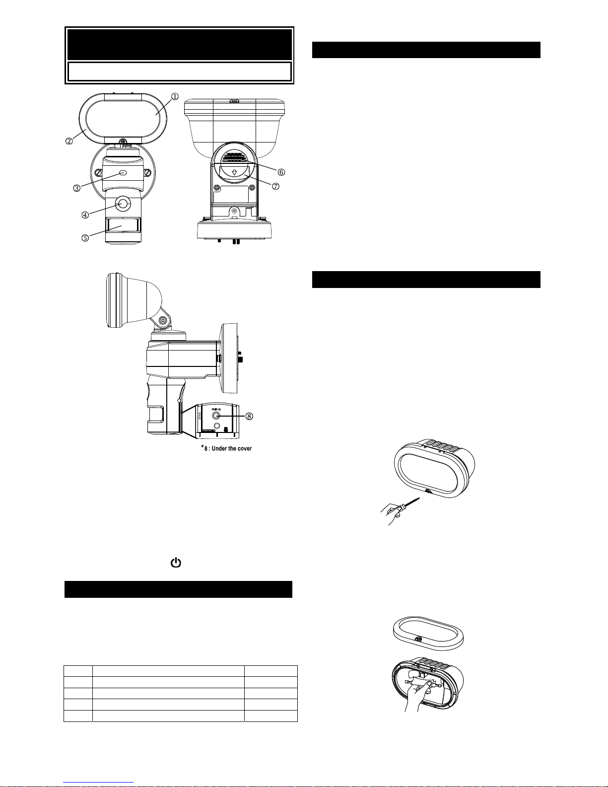
① Floodlight
② Lampshade
③ Microphone
④ Camera
⑤ PIR (Motion Sensor)
⑥
Speaker
⑦ Pair/Power Button Cover
⑧ Pair/Power (PAIR/ ) Button
PACKAGE CONTENT
The Smart Safe Cam is packed specially to minimize
the chance of the contents being damaged during
shipping and handling. Please check the unit carefully
and confirm the contents listed below are included.
No. Item Qty
1 Base Unit 1
2 Screw Pack 1
3 Halogen Bulb 1
4 Operating Instruction Manual 1
INTRODUCTION
Your SMART SAFE CAM is a unique surveillance
system for your home or business. At night, the
built-in passive infrared (PIR) motion sensor turns on
the light when it detects motion in its coverage area, so
that camera images can be clearly seen. During the
day, the built-in photocell sensor saves electricity by
deactivating the light. This camera can link up with a
control panel (after code learning) and save the
recorded image on the panel. Pre-recording function
allows you to trace event happening, and function
settings can be done via the control panel.
The unit is designed for both indoor and outdoor
usages.
Note: Read this entire manual before you start to install
the system.
BEFORE START
BULB INSTALLATION
CAUTION: Always handle quartz halogen bulb with a
soft cloth. Do not touch the bulb with your bare hand
as it will shorten the bulb life.
(1) Do not touch the light while it is in use or still hot.
Allow it to cool off (about 5 minutes) before
touching it.
(2) Do not use halogen bulb rated higher than 150/120
watts.
(3) Disconnect the power cord or wall switch and then
use a cross head screwdriver, loose the screw at
the bottom edge of the front surround (FIGURE 1).
FIGURE 1
(4) Take off the front surround. Install bulb by inserting
one end first and depressing until enough
clearance is gained to seat the other end of the
socket. Rotate halogen bulb to assure proper
seating. Refit the front surround in place and
fasten the screw (FIGURE 2).
FIGURE 2
Side View &
Interior View
Front View B
otto
m View
2
CHOOSING A MOUNTING LOCATION
For the best results, fix the unit on a solid surface,
2.5m above the ground.
Avoid aiming the unit at pools, heating vents, air
conditioners or objects which may change
temperature rapidly .
Do not allow sunlight to fall directly on the front of
unit.
Try to avoid pointing the unit at trees or shrubs or
where the motion of pets may be detected.
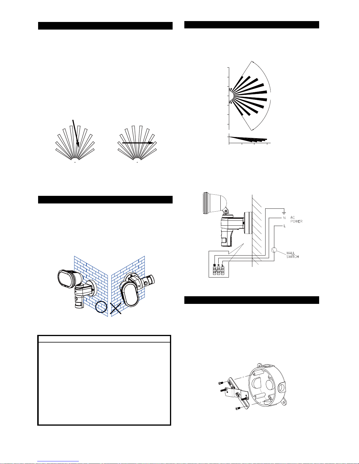
The motion sensor is more sensitive to objects
moving across its field of view. It is less sensitive
to an object moving directly towards the sensor
head. (FIGURE 3).
MORE SENSITIVE
SENSOR
LESS SENSITIVE
SENSOR
SENSITIVITY TO MOTION
FIGURE 3
SAFETY PRECAUTIONS
Do not install the product in storming or raining
weather.
Be su re to switch of f power source before inst alling.
To avoid fire or burn hazards:
Allow fixture to cool before touching.
The product installed must parallel to the ground as
shown in the following figure. (FIGURE 4)
FIGURE 4
IMPORTANT
Installation must be performed by skilled technicians
who are informed about the standards and technical
requirements of the appliance and its proper
installation.
Check your local codes as they apply to your
situation. If the house wiring is of aluminum, consult
with an electrician about proper wiring methods.
Before proceeding with the installation, TURN OFF
THE POWER TO THE LIGHTING CIRCUIT AT THE
CIRCUIT BREAKER OR FUSE BOX TO AVOID
ELECTRICAL SHOCK.
INSTALLATION
A drill and a screwdriver are needed for installation.
Select a location for the unit based on the coverage
angles as shown in FIGURE 5 (110° at 8m range).
TOP VIEW
0
12
2
4
8
4
0
12
8
84
SIDE VIEW
12
UNIT:m
1
1
0
°
FIGURE 5
Install a wall switch adjacent to the power source
(FIGURE 6). This will help you operate SMART SAFE
CAM with ease.
FIGURE 6
WIRING INSTRUCTION
American Version
(1) Switch off the power source or wall switch.
(2) Line up the holes on the mounting bracket with the
holes on your junction box. Using fitting screws
(depending on size of the holes in your junction
box), and attach the mounting bracket to your
junction box (FIGURE 7).
FIGURE 7
 Loading...