

Lynteck TITAN TF20WLED Quick Start Manual
TITAN
‚ ƒ •
180° 110°
10W x 2 LED FLOODLIGHT
•
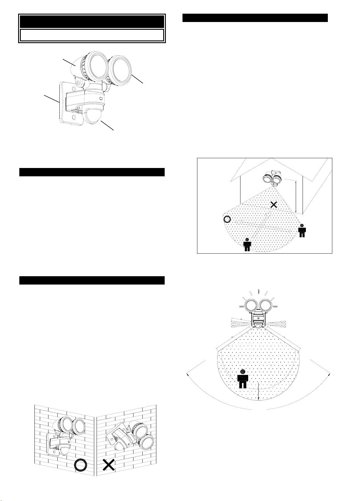
• LED lamp heads
‚ Wall mount / terminal block
ƒ PIR detector
INTRODUCTION
The Titan twin head 20W LED Floodlight offers you an
economical lighting solution with extremely low energy
consumption.
During darkness, the built-in passive infrared (PIR)
sensor turns on the Floodlight when the PIR sensor
detects a moving heat source in its coverage area. During
daylight, the built-in photocell sensor saves energy by
deactivating the Floodlight.
Note: Please read this entire manual before you start
installation.
SAFETY PRECAUTIONS
l DO NOT install when it is raining.
l Isolate the power supply before installation.
l UK Building Regulations require outdoor mains
installations be carried out by a qualified electrician.
l BS7671: 2008 IEE Wiring Regulations must be
complied with in all respects.
l HO5RNF round flexible cable and drip loops must be
used to avoid water ingress damage to the unit.
l Ensure that the power supply is protected by a 6A
circuit breaker or suitable fuse.
l Ensure minimum distance of 0.5m away from lighted
objects.
l The unit must be installed vertically (FIGURE 1a)
NOT horizontally (FIGURE 1b).
VERTICAL HORIZONTAL
FIGURE 1a FIGURE 1b
CHOOSING A MOUNTING LOCATION
l For the best results, mount the Floodlight onto
normal brickwork 2.5m above the ground.
l Avoid aiming the PIR sensor at pools, heating vents,
air conditioners or objects that may change
temperature.
l Avoid pointing the PIR sensor at trees or shrubs or
where the movement of pets or animals may be
detected.
l Avoid locations where direct sunlight will shine onto
the front of the PIR sensor for long periods,
deterioration of the Fresnel lens may occur leading
to poor triggering response.
l Prior to mounting, keep in mind that the PIR sensor
is more sensitive to a heat source moving across its
coverage area and less sensitive to a heat source
that moves directly towards the PIR sensor
(FIGURE 2).
FIGURE 2
Select a location for the unit based on the coverage
angles shown in FIGURE 3.
180¢X
1 2 m
110¢X
COVERAGE ANGLES
FIGURE 3
2.5m
2m
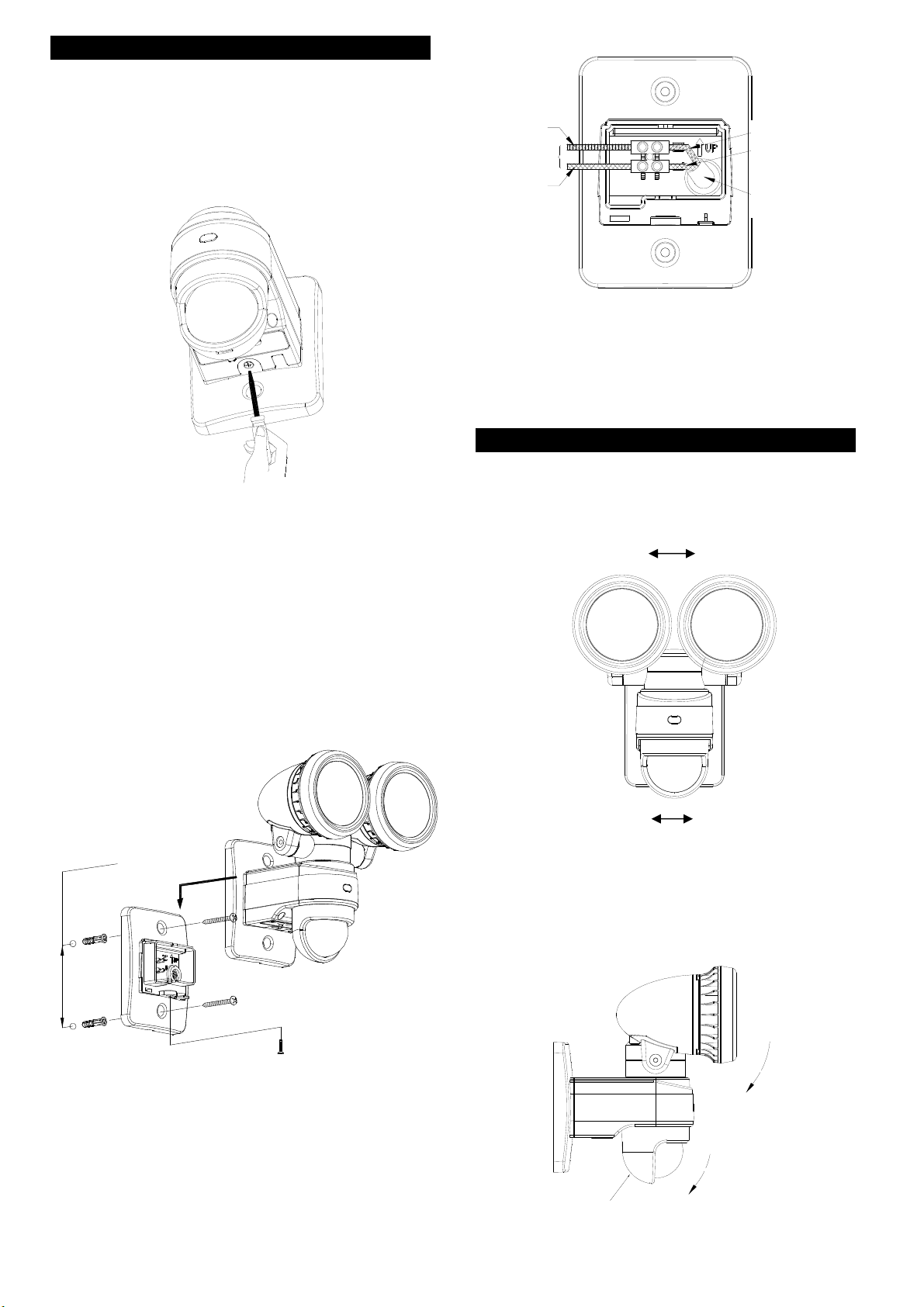
WIRING INSTRUCTION
37.5¢X
Adjustment
(1) WARNING isolate the power supply. An internal
single pole wall switch is recommended to allow
easy control of the floodlight.
(2) Detach the wall box by unscrewing the screw
adjacent to the control knobs (retain the screw for
later use). (FIGURE 4)
FIGURE 4
(3) Use a braddle to punch a small hole in the cable
grommet, enabling the supply cable to enter the wall
box.
(4) Route the supply cable through the cable grommet.
A drip loop is required between the wall box and the
wall to avoid water ingress.
(5) Determine the correct location to mount the
floodlight. Use the wall box as a template to mark
the fixing holes on the wall. Drill the holes and insert
the plastic wall plugs supplied. Fix the wall box using
the screws provided. (FIGURE 5)
BLUE
TO LAMP
BROWN
NEUTRAL
NEUTRAL
LIVE
LIVE (VIA WALL SWITCH)
AC POWER
SUPPLY CABLE
FIGURE 6
(8) Locate and mount the Floodlight onto the wall box
and secure with the retaining screw (DO NOT over
tighten).
ANGLE ADJUSTMENTS
The LED Lamp Heads can be adjusted 45° left and 45°
right; the PIR sensor can be adjusted 90° left and 90°
right. (FIGURE 7a)
LEFT 45¢X
LEFT 45° RIGHT 45°
RIGHT 45¢X
m
m
5.38
FIGURE 5
(6) Strip approximately 6-8mm of inner core insulation
from the supply cable.
(7) Connect the BROWN wire (Live wire) to the terminal
marked “L”.
Connect the BLUE wire (Neutral wire) to the terminal
marked “N”. (FIGURE 6)
NB: The floodlight is double insulated no earth is
required.
LEFT 90¢X
LEFT 90° RIGHT 90°
RIGHT 90¢X
FIGURE 7a
The LED Lamp Heads can be tilted 37.5° down. The PIR
sensor has an adjustment slider on the rear of the unit.
This slider is used to tilt the angle of PIR sensor down to
30° maximum. (FIGURE 7b)
37.5°
30¢X
30°
Slider
FIGURE 7b
 Loading...