

Page 1

1
LS800S Intruder Alarm System
Engineering Manual
Table of Contents
Section 1 – Overview of System
1.1 Kit Contents
1.2 Tools Required
1.3 System Features
Section 2 – Planning your installation
2.1 Location of components
2.2 Planning the location for the system components
Section 3 – Installation your system
3.1 Control Unit
3.2 Movement Detector/PIR
3.3 Door/Window Detector
3.4 Remote Key Reader
3.5 Bellbox
3.6 Testing the system
Section 4 – Using your system
4.1 Normal Operation
4.2 Learn the first remote keys
4.3 Select entry timer
4.4 Summary of the zones in different mode
4.5 Summary of Factory Settings
4.6 Status of LED indications
Section 5 – Maintenance
Section 6 – Extending your system
Section 7 – Specifications
Page 2
2
SECTION 1 – OVERVIEW OF SYSTEM
The LS800S system is an indoor alarm system based on our patented two-wire technology to
give exceptional levels of protection and reliability. It is a fuseless system with special
electronic design for short-circuit protection. It is simple to use, easy to install, no special
tools or training is required.
IMPORTANT – Please read this manual carefully, in full, before commencing Installation. You
will find installation easier if you follow these steps in the sequence shown.
1.1 Kit Contents
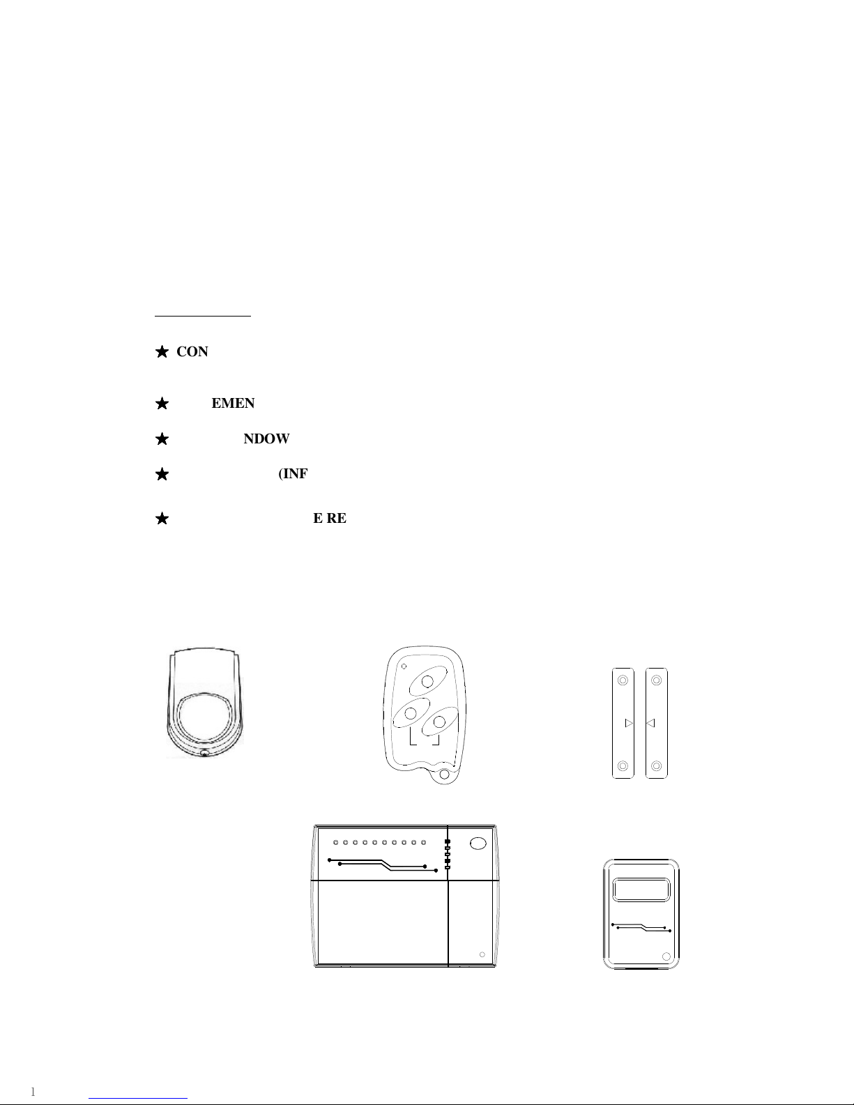
The system comprises of:
★★★★
CONTROL UNIT
This main unit receives signals from detectors, accepts input from users and activates warning
devices.
★★★★
MOVEMENT DETECTOR PASSIVE INFRA-RED (PIR) (Two units)
It senses body heat of moving person; one unit may cover entire room.
★★★★
DOOR/WINDOW CONTACT (Three pairs)
Uses a magnetically operated switch to sense the opening of door or window.
★★★★
REMOTE KEY (INFRA RED REMOTE KEY) (Two units)
They are pre-learnt and used for operation commands to the Control Unit.
★★★★
INFRA RED REMOTE READER
An extension of the infrared receiver to facilitate remote operation of the system from any
convenient location.
The alarm kit also contains:
- Screw / wall plug pack.
To complete your installation, you also require: (You need to purchase separately)
- Rechargeable battery 12V, 1.2Ah or 2.0Ah
- Two core flat wires and clips.
F
U
L
L
A
R
M
P
A
R
T
I
A
L
D
I
S
A
R
M
A
R
M
PANI C
Error
Learn
Part Arm
Day
Power
LS800-S
Zo
n
e
1
Z
on
e
2
Zo
n
e
3
Z
on
e
4
Zo
n
e
5
Zo
n
e
6
Zone 8
P
A
Tamp
e
r
Zo
n
e
7
TWO WIRE SYSTEM
E
IR
w
II
Part /Hold
Power
IRR308
TWO WIRE SYSTEM
II
w
IR
E
DOOR/WINDOW CONTACTS
PIR
CONTROL UNIT
REMOTE KEY
INFRA RED
REMOTE
Page 3

3
1.2 Tools Required
The following tools are required for installation:
★
Large & small flat bladed screwdrivers and cross point screwdrivers
★
Hammer
★
Power drill
★
Wire cutters and wire stripper
★
Eye protection (recommended when using a power drill or hammer)
1.3 System Features
★
Simple and effective Eight-zone system with the new patented two-wire technology.
★
All system components (sensors, bellbox) are connected to the Control Unit via two-core
non-polarity flat wires. Wiring and installation of the system is extremely simple and
easy.
★
Control Unit has built-in infrared receiver, with status LEDs and zone indicators. Panic
and tamper attempts will be indicated by the status LEDs.
★
Maximum 8 remote keys can be accepted for full arm, part arm, disarm, panic and learn
key functions
★
“Full arm” and “Part arm” modes are pre-programmed for user convenience.
★
The tamper zone is indicated by both Tamper LED and Zone LED (for Zone 4 to 8).
★
All sensors, bellbox are 24 hour line-protected and fully supervised; any attempt to
interfere with the system will trigger the alarm and be identified by flashing LEDs and
zone indicator.
★
Two PIR motion detectors can be connected to one zone, therefore the system can be
expanded to have ten PIR’s plus many magnetic contacts. Also, easy connections are
provided for adding telephone dialer to the system.
★
Remote key reader is available for user convenience.
★
Optional two wire bellbox is available
★
Optional normal bellbox connection terminals are provided.
★
Optional voice dialer is available to increase the security level.
Page 4
4
SECTION 2 – PLANNING YOUR INSTALLATION
2.1 Location of components
Control Unit – Location
In choosing a suitable location you should bear in mind:
★
The user needs to reach the Control Unit or Remote Key Reader easily within the
allocated time, when entering and leaving the premises.
★
The Control Unit should not be visible from the exterior of the protected premises.
★
All detectors and the bellbox must be wired to the Control Unit.
Having chosen the location do not mount at this stage.
Movement/Passive Infra Red Detector (PIR) – Location
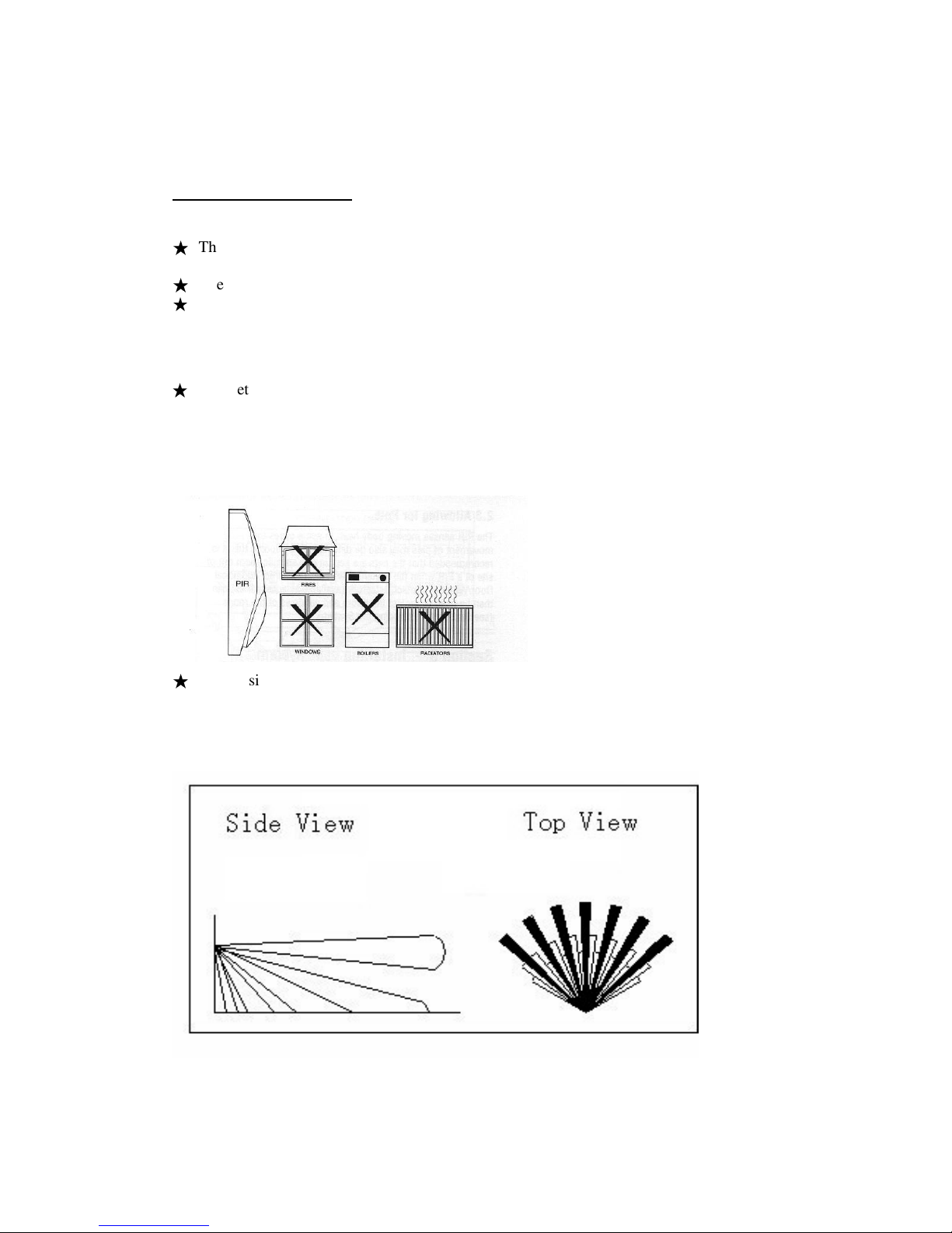
★
The detector should not be mounted near to large metal objects or on metal surfaces. It
needs to be mounted on a wall or in a corner at a height of approximately 2 to 2.5meters
for the best general coverage in an average room. The detector has been designed to avoid
false alarms, nevertheless, it is best to avoid looking directly at sources of heat such as
fires and boilers, and always try to keep away from a window. A PIR can look at a
radiator but should not be sited above one.
★
Do not site a PIR where its field of view may be obstructed (e.g. by curtains). Also note
that PIRs work best when sensing movement across rather than along their detection
beams. You need to consider the need to wire these units back to the Control Unit.
Detection Area of PIR
Having chosen the location do not mount at this stage.
Page 5
5
Door/Window Contact Detectors – Location
★
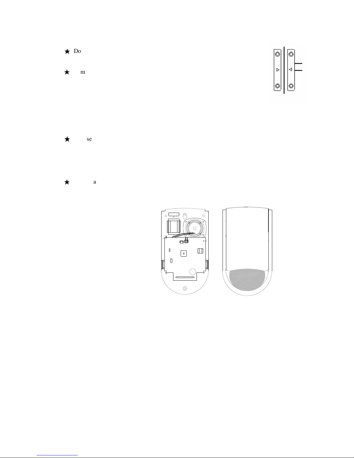
Door / Window Contact Detector is designed to detect a door or window
opening, so it is better mounted onto the frame with a magnet mounted next to
it on the door or window.
★
In most applications one door contact is fitted to the front door and assigned to
ZONE 1 which is the Entry/Exit Zone. When the system is set at “Full arm”
mode, Zone 1 allows a 30 second (adjustable) delay for the user to enter or
leave the house, and should be the only zone activated before reaching the
Control Unit on entering the premises. The other contact detectors can be
mounted to the back door or window and assigned to Zone 2 or 3.
Having chosen the location do not mount at this stage.
Infra Red Remote Reader - Location
★
Choose a location near the most frequently entry/exit door, so that the arming and
disarming of the system can be done conveniently when user exit/entry the premises.
Having chosen the location do not mount at this stage.
Two-wire Bellbox (Optional) – Location
★
Choose a location for the bellbox, preferably in
a prominent position high up on an external
wall,
taking into account that it must be wired back to the Control Unit. The cable should
ideally run directly from behind the bellbox through the wall to the inside. This is to avoid
any cable running along the exterior wall that could be reached by an intruder.
Having chosen the location do not mount at this stage.
Page 6
6
2.2 Planning the location for the system components
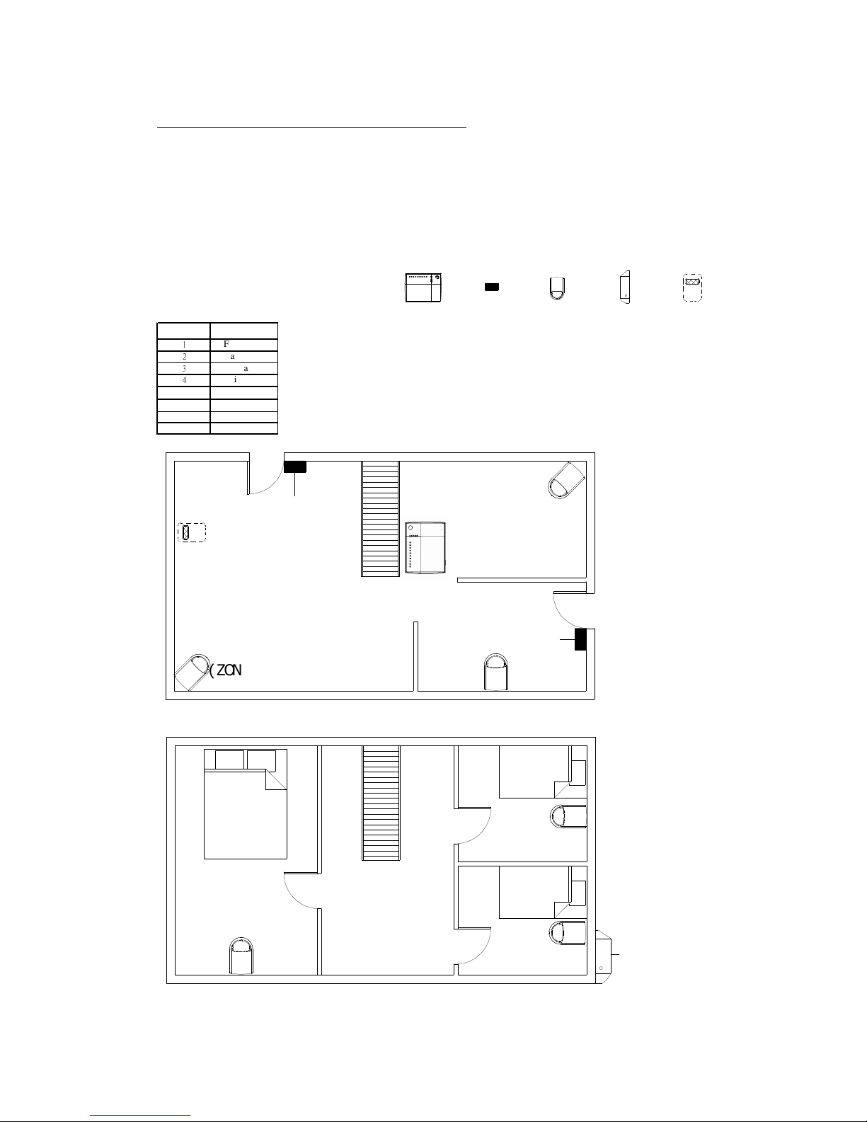
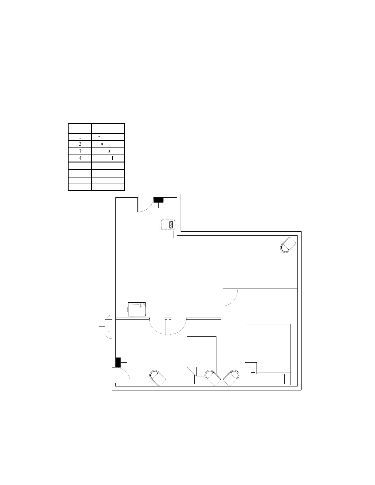
Example of a domestic layout
The 2 sample layouts below are intended as guides only but demonstrate two examples of
how a house can be protected with the system.
Sample 1: Two storey house Legend
LS800-S
Power
Day
Part Arm
Learn
Error
Z
o
ne
1
Z
on
e
2
Z
one
3
Z
one 4
Z
one 5
Z
o
ne
6
Z
on
e
8
P
A
T
amp
er
Zone
7
Zone Area
1
Front Door
2
Back Door
3
Spare
4
Living room
5
Dining room
6
Kitchen
7
Bedroom #1
8
Bedroom #2,#3
( ZONE6)
KI TCHEN
LS800S
CONTROL UNIT
( ZONE4)
(ZONE5)
DINI NG ROOM
LI VING ROOM
(ZONE1)
(ZONE2)
BEDROOM
BEDROOM
BEDROOM
BELLBOX
( ZONE8)
( ZONE8)
( ZONE7)
#1
#2
#3
Ground Floor
2nd Floor
Control
Unit
Door/window
Contact
detector
PIR
Bellbox
Remote
Key
Reader
LS800S
CONTROL UNIT
Page 7
7
The PIRs have been placed in different rooms and those placed in bedrooms are only
protected on full arm. The Door/Window Contact Detectors have been positioned to protect
the front door and back door.
Sample 2: Single storey house
Zone Area
1
Front Door
2
Back Door
3
spare
4
Hall
5
Spare
6
Kitchen
7
Bedroom#1
8
Bedroom#2
BELLBOX
KI TCHEN
HALL
BEDROOM
#2
LS800S
CONTROL
UNI T
BEDROOM
#1
(ZONE7)
( ZONE4)
(ZONE8)
(ZONE6)
( ZONE2)
( ZONE1)
REMOTE
KEY
READER
The Zone 4 PIR has been placed in the Dining/Living room to protect this general area. The
Zone 7 and Zone 8 PIRs has been placed in bedrooms to protect the personal valuables there.
They are disabled when the system is set at “Part Arm” mode. The Door/Window Contact
Detectors have been positioned to protect the front door and back door.
Page 8
8
SECTION 3 – INSTALLING YOUR SYSTEM
3.1 Control Unit
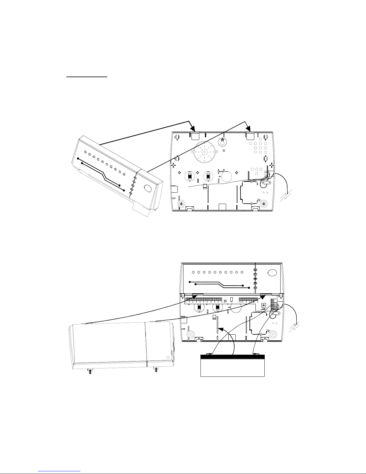
Remove and retain the two holding screws from the bottom of the front cover and
carefully hinge off the front cover of the control unit.
Mark and drill holes for the three mounting screws. Put in the wall plugs and have a
mounting screw on the top (hanging screw) inserted. Hang the Control Unit on the
hanging screw and fixed it with two screws on the bottom. (Illustration 1)
E
r
ro
r
L
e
a
r
n
P
a
r
t
A
r
m
D
a
y
P
o
w
e
r
T
W
O
W
I
R
E
S
Y
S
T
E
M
P
A
T
a
m
p
e
r
Z
o
n
e
8
Z
o
n
e
7
Z
o
n
e
6
Z
o
n
e
5
Z
o
n
e
4
Z
o
n
e
2
Z
o
n
e
1
Z
o
n
e
3
Illustration 1
Fix the upper part of the front cover on the bottom. (Illustration 1)
Connect the rechargeable battery on to the control unit and fix it by the battery clips.
(Illustration 2)
Error
Learn
Part Arm
Full Arm
Power
TAMP
DETECTOR
ZONEZONE
21
ZONEZONE3ZONE54ZONEZONE
6 7
ZONE8TW
IR
BELLBOX
TW
TAMP
SET
EXT LS
+ -
B/T GND
STBBELL
DIAL+VE
TIG
TWO WIRE SYSTEM
PA
Zone
7
Tamper
Zon
e
8
Zone
6
Zone 5
Z
one
4
Z
one
3
Zone
2
Z
one
1
14V
+
~
-
DC
BATT
AC
~
12V 12V
BATT
DC
-+
LS800-S
II
w
IR
E
VOLUME
CPTAM1
CPTAM1
CPTAM1
CPTAM1
WALK/ALARM TEST
Illustration 2
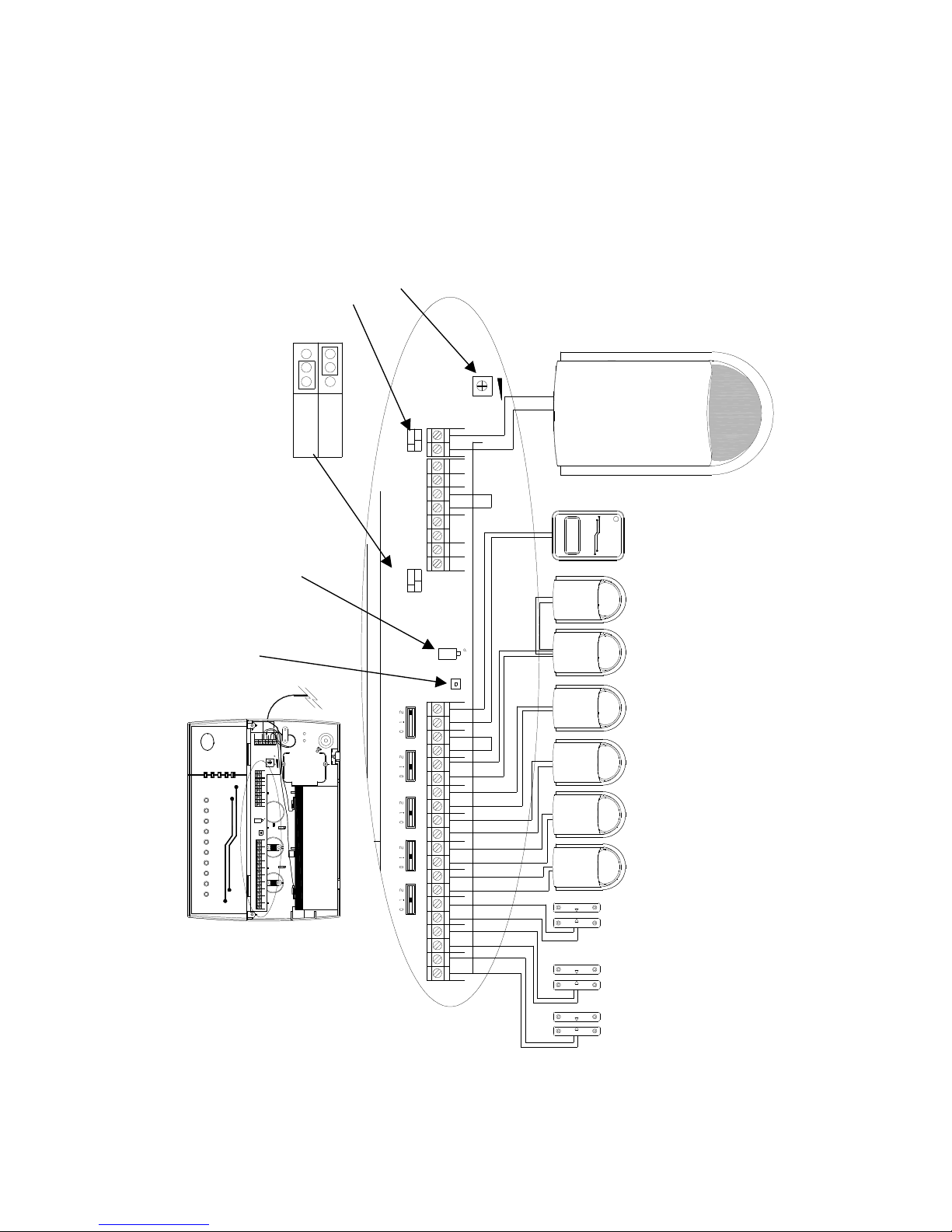
Have all the sensors (magnetic contacts, PIRs) and optional accessories (Bellbox, or
dialer if fitted) wired up and connected to the corresponding terminals in the Control Unit
(Illustration 3). Also wire up the main power adapter and rechargeable battery to the
Battery
Page 9
9
Control Unit. DO NOT plug in the power plug to the main supply until all connections
are completed and all units properly mounted and front cover of the Control Unit is
closed and secured.
WARNING: All connection to the mains should be made in accordance with all relevant
wiring regulations. The Control Unit must never be operated from the mains with the
front cover removed.
Day
Error
Learn
Part Arm
Power
TAMP
DETECTOR
ZONEZONE
21
ZONEZONE
3
ZONE
5
4
ZONEZONE
6 7
ZONE
8
TW
IR
BELLBOX
TW
TAMP
SETEXT LS
+ -
B/T GND
STBBELL
DIAL
+VE
TIG
Z
one 1
Zone 2
Zone 3
Z
one 4
Zone 5
Zone 6
Zone 8
T
amper
Zone 7
TWO WIRE SYSTEM
PA
+ -
DC
BATT
12V12V
~
AC
BATT
DC
-~+
14V
CPTAM1
CPTAM1
CPTAM1
VOLUME
WALK/ALARM TEST
CPTAM1
(AC/AC ADAPTER)
WALK/ALARM TEST CPTAM 1
CPTAMP1
CPTAMP1
CPTAMP1
VOLUME
Part/Hol d Power
IRR308
TWO WIRE SYSTEM
II
w
IR
E
15S
30S
ENTRY TI ME
JP6 JP7
TW/ BELL
ON
OFF
TIG
+VE
DI AL
STBBELL
B/T GND
+ -
EXT LS
SET
TAMP
TW
BELLBOX
I R
TW
8
ZONE
76
ZONE ZONE
4
5
ZONE
3
ZONE ZONE
1 2
ZONE ZONE
DETECTOR
TAMP
GND
ZONE8
ZONE7
ZONE6ZONE5ZONE4
30Second
15Second
Illustration 3
Two Wire Bellbox
Two wire PIR
(Note 2)
Magnetic Contact Zone
(Note 1)
Infra Red
Remote
Reader (Note 4)
TW Bellbox Jumper
Walk/Alarm test
button
VOLUME
Entry time jumper
Tamper
Page 10

10
NOTE 1: For connecting magnetic contacts to any of Zone 1-3, (For more information please
refer Illustration 10).
NOTE 2: Illustration 3 show one piece of 2-wire PIR detector is connected to each of Zone 4
to Zone 7; and therefore the PIR zone slide switches opposite the PIR zone
terminals are put in position 1. For connecting two pieces of PIR on the same zone
(Zone 8), you need to put the corresponding slide switch to position 2. (For more
information please refer Illustration 7)
NOTE 3: If you need to skip the PIR zone, you need to put the corresponding slide switch to
position 0. (Factory setting)
NOTE 4: If more than one Infra Red Remote Reader is used, they can be connected in parallel,
as shown in Illustration 7.
Page 11
11
Connect the two
wires to these
two screw terminals
Illustration 6
3.2 Movement Detector/PIR
★
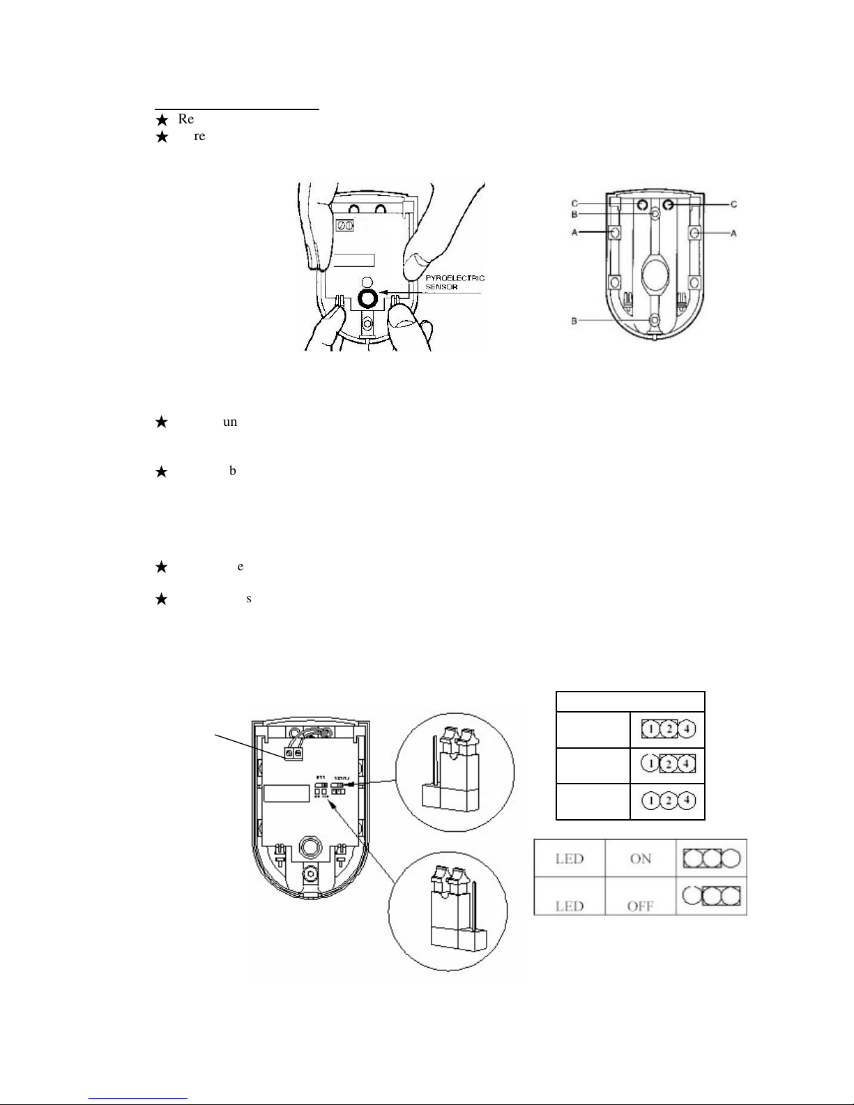
Remove and retain the screw from the bottom of the PIR and lift off the cover.
★
Carefully remove the electronic module from its retaining clips, ensuring not to touch
the pyroelectric sensor (Illustration 4).
Illustration 4
Illustration 5
★
Use mounting points “A”, if you are fitting the detector in a corner. Use mounting points
“B”, if you are fitting the detector on a flat surface. Use a small drill to create two fixing
holes at the mounting points (Illustration 5).
★
Hold the base of the PIR in the chosen position, ensuring that the front of the PIR will face
towards the center of the protected area, mark and drill two fixing holes in the wall.
Choose one of the cable entry holes “C” and make a third hole in the detector base. Put one
end of the 2-core wire through this hole “C”, then secure the PIR to the wall using two
screws and wall plugs provided.
★
Replace the electronic module into the retaining clips, ensuring that it is correctly positioned
and firmly seated.
★
If required, select the PIR LED “ON” or “OFF” option and the sensitivity (pulse count) by
setting the corresponding jumpers on the electronic module. Note that Pulse 1 option is more
sensitive than the pulse 4 option. Pulse 1 option is used when it is necessary to activate an
alarm on the first detected pulse, or in high security installations – where fast “catch”
performance is of greatest importance. Pulse 2 or 4 settings provides improved protection
against false alarms caused by all types of environmental disturbances. (Illustration 6)
Pulse Count
Pulse 1
Pulse 2
Pulse 4
Page 12
12
★
Connect the 2 wires to the PIR, polarity is not important.
★
Run the cable back to the Control Unit, fixing the cable with cable clips and enter the wire
into the back of the Control Unit through any convenient cable hole.
★
Connect to one of the two wire PIR zone (zone 4 to zone 8) terminals in the Control Unit as
required. Connection polarity is not important. (Illustration 3).
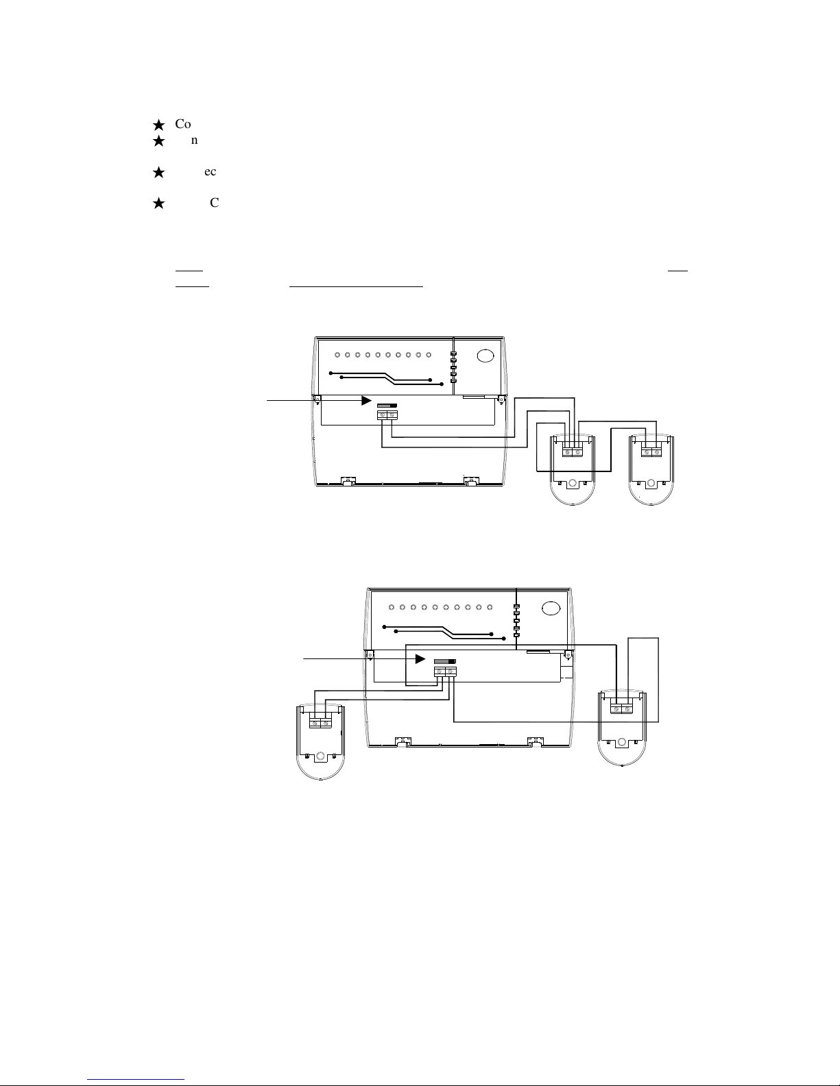
★
In the Control Unit, against each of the two-wire PIR connection terminals (zone 4 to zone 8),
there is a 3-position (0,1,2) slide switch. These switches are factory pre-set at position “0”
when no PIR is connected. When connecting one piece two-wire PIR to the zone, you need to
set the corresponding switch to position “1”. When connecting 2 pieces two-wire PIR to the
same zone terminals, put the corresponding switch to position “2”. The wiring to connect two
pieces 2-wire PIR to one same zone terminals are as Illustration 7.
When the two PIRs are running in the same direction:
TWO WIRE SYSTEM
PA
Zone 1
Z
one
2
Zone 3
Zone 4
Z
o
ne
5
Z
one
6
Z
one
8
Tamper
Z
one
7
Power
Part Arm
Learn
Error
Day
0 1 2
When the two PIRs are running in opposite directions:
PA
TWO WIRE SYSTEM
Zone 7
Ta
m
per
Z
o
ne 8
Zone 6
Zo
ne
5
Z
o
ne 4
Zone 3
Zo
n
e 2
Zone 1
Day
Error
Learn
Part Arm
Power
0 1 2
Illustration 7
★
Replace cover on PIR and refit the retaining screw.
(Switch at
Position 2)
(Switch at
Position 2)
Page 13
13
3.3 Door/Window Contact Detector
★
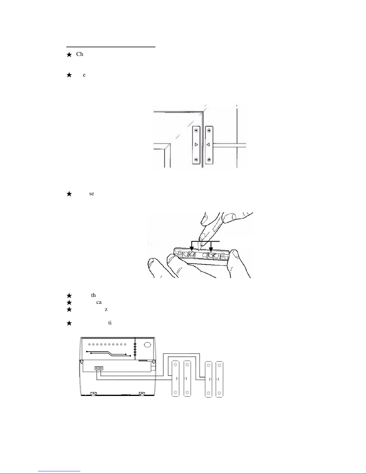
Choose the location for each magnetic contact (remembering the need to wire them back to
the Control Unit). Each contact consists of a magnetically-operated switch (with screw
terminals at the back) and a magnet in an identical housing.
★
The switch (the part with screw terminals and cable) should be mounted on the frame. The
magnet should be mounted on the door or window itself directly opposite the switch, no more
than 8mm apart when the door or window is closed (Illustration 8). Mark two mounting holes
for the magnet on the door or window and two mounting holes for the switch on the frame.
Illustration 8
★
Choose a convenient entry point for the cable on the switch housing and carefully remove part
of the plastic using a sharp knife to create a hole (Illustration 9). Connect the 2 wires to the
two screw terminals.
Illustration 9
★
Fixed the contact and magnet in position using the four mounting screws provided.
★
Run the cable back to the Control Unit.
★
Connect to zone 1, zone 2 or zone 3 terminals of the Control Unit as required. Connection
polarity is not important.
★
If two magnetic contacts need to be wired to one same zone (zone 1, zone 2 or zone 3), wire
them up in serial connection as Illustration 10.
PA
Zone 7
Tamper
Z
one 8
Zone 6
Zone 5
Zone 4
Z
one 3
Zone 2
Zo
ne 1
TWO WIRE SYSTEM
Day
Error
Learn
Part Arm
Power
Illustration 10
WINDOW
FRAME
Page 14
14
3.4 Infra Red Remote Reader
★
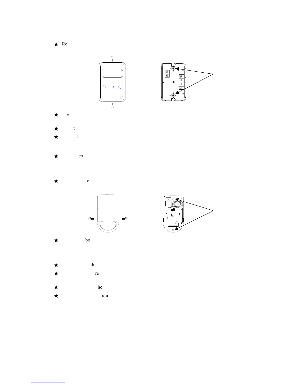
Remove the cover retaining screws from the top and the bottom of the Reader cover
(Illustration 11). Take off the cover from the reader baseplate.
IRR308
TWO WIRE SYSTEM
E
IR
w
II
Part /Hold
Power
★
Use the reader baseplate as a template to mark and drill fixing holes (Illustration 12) on the
wall at the chosen position.
★
Mount and fix the baseplate of the reader with the screws and wall plugs provided.
★
Connect the 2-wire cable to the terminals inside the Infra Red Remote Reader, and the other
end of the cable to the corresponding terminals in the Control Unit. (See Illustration 3).
Maximum 3 Remote Key Readers may be connected in parallel.
★
Replace cover on the Reader and refit retaining screws.
3.5 Two wire Bellbox TW-972 (Optional)
★
Remove the cover retaining screw from the base of the bellbox cover (Illustration 13). Take
off the cover from the bellbox baseplate.
★
Use the bellbox baseplate as a template to mark and drill fixing holes (Illustration 14) on the
wall at the chosen position. For mounting the bellbox outside the house, drill a further hole
through the wall directly behind the bellbox for the 2 core cable to run through from the
Control Unit to the bellbox.
★
Mount and fix the bellbox with the screws and wall plugs provided.
★
Connect the 2-wire cable to the terminals inside the bellbox, and the other end of the cable to
the corresponding terminals in the Control Unit. (See Illustration 3).
★
Replace cover on the bellbox and refit retaining screws.
★
Put the TW bellbox jumper on the control panel to the ON position. (See Illustration 3).
(For details please refer to the TW-972 Two Wire Bellbox instruction)
Illustration 13
Illustration 14
Fixing holes
Illustration 11
Illustration 12
Fixing holes
Page 15

15
3.5 Testing the system
★
After installation is completed, plug in the main power supply. The “Power” indicator will
illuminate showing that the system is starting to work. Wait about two minutes for the system
to get ready.
★
Walk tests – each detector to be checked in order to verify they are functioning correctly.
1. Open the bottom cover of the control unit. Note that the tamper alarm appears. You may
adjust the beep sound by adjusting the VOLUME by a small screw driver.(Illustration 3)
2. Press the ‘DISARM’ button on the recognized remote key to stop the alarm. Tamper
LED ‘
¤¤¤¤
Tamper
’
will flash to give tamper indication.
3. Press the PCB mounted WALK/ALARM TEST push button momentarily. (Illustration 3)
The system will go into walk test. Day LED is flashing.
4. Upon activation of any zone, the relevant Zone LED ‘
※※※※
’
will latch up and a ‘Zone fault’
tone (continuous short beeps) is emitted.
5. Pressing the push button again at any time will clear the latched LED and walk test is
restarted.
6. On completion of walk test, close the cover of the control unit and an ‘OK’ tone (two
rapid beeps) is emitted and Day LED is on.
★
Alarm tests – test the strobe, siren, low and high volume sounders of the system, SET output.
N. B. Alarm test may be activated while in walk test mode (go straight to step 3)
1. Open the bottom cover of the control unit. Note that the tamper alarm appears.
2. Press the ‘DISARM’ button on the recognized remote key to stop the alarm. Tamper
LED ‘
¤¤¤¤
Tamper
’
will flash to give tamper indication.
3. Press the PCB mounted WALK/ALARM TEST push button for 3-5 seconds.
(Illustration 3). Day LED is flashing.
4. The tests are performed consecutively. Advance to next test automatically after 3
seconds
a) Low volume sounder on LS800S control panel
b) High volume sounder on LS800S control panel and strobe
c) External bell and strobe
d) Set terminal +ve output and strobe
5. On completion of walk test, close the cover of the control unit and an ‘OK’ tone (two
rapid beeps) is emitted and Day LED is on.
Page 16
16
SECTION 4 – USING YOUR SYSTEM
4.1 Normal operation
Normal operation with the remote key, such as full arm, part arm, disarm, panic and learn a new
remote key function are described in the “LS800S Security System Operation Manual”
N.B. Remote keys provided are factory pre-learnt. Learning procedure is not necessary.
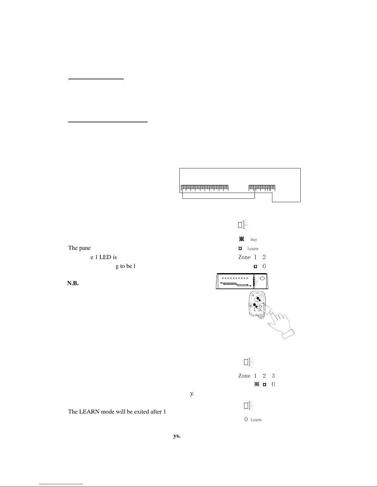
4.2 Learn the first remote keys
When all the remote keys are lost or not recognized by the LS800S system, you may need to
re-learn all remote keys into the system. The control panel will remove all registered keys
previously learned.
Ensure a wire is connected between first terminal of Zone 1 and Set terminal.
TAMP
DETECTOR
ZONEZONE
21
ZONEZONE3ZONE54ZONEZONE
6 7
ZONE
8TWIR
BELLBOX
TW
TAMP
SET
EXT LS
+ -
B/T GND
STBBELL
DIAL +VE
TIG
Power up LS800S control panel.
5 rapid beeps
Learn LED is flashing.
※※※※
Day
The panel is in LEARN mode.
¤¤¤¤
Learn
Only zone 1 LED is flashing indicates the first
Zone 1 2
remote keys is going to be learned.
¤¤¤¤
O
F
U
L
L
A
R
M
P
A
R
T
I
A
L
D
I
S
A
R
M
A
R
M
PANIC
Error
Learn
Part Arm
Day
Power
Zone 1
Zone 2
Zone 3
Zone 4
Zone 5
Zone 6
Zone 8
PA
Tampe
r
Zone 7
TWO WIRE SYSTEM
Press PART ARM button and DISARM button simultaneously on a new remote key.
A recognized beep and the flashing LED is changed to
recognized beep
steady. The next numbered zone LED is flashed.
Zone 1 2 3
※※※※
¤¤¤¤
O
Repeat previous step to learn other new remote key.
The LEARN mode will be exited after 10 seconds timeout
two beeps
if no action is taken to learn new remote key.
O
Learn
Remove the wire between Zone 1 and Set terminals.
N.B. LS800S can learn up to 8 remote keys.
N.B. The learn mode will NOT expire until
the first remote key is learned.
Page 17

17
4.3 Select Entry Timer
The entry timer jumper on the control panel (See Illustration 3) is set to 30 seconds (default
setting) which allows user to enter the premises and unset the system within 30 seconds.
User may put the entry timer jumper on the control panel to 15 seconds which allows user to enter
the premises and unset the system within 15 seconds.
4.4 Summary of the zones in different mode
Zone Full Arm Part Arm Usage
1 Delay Delay Exit/Entry zone
2 Instant Instant
Protect door/window which are
not often used
3 Instant Instant
Protect door/window which are
not often used
4 (TW-PIR) Delay Delay
Protect area close to exit/entry
zone
5 (TW-PIR) Delay follower Delay follower
Protect area on the path between
control unit and exit/entry zone
6 (TW-PIR) Instant Instant
Protect area when part arm is
used
7 (TW-PIR) Instant Omit Protect area for full arm only
8 (TW-PIR) Instant Omit Protect area for full arm only
4.5 Summary of Factory Settings
Factory Preset Can be changed
by User to
Manual Reference
Control Unit
(1) Learn Remote Key 2 pre-learned Additional 6 keys Section 4.1
(2) Instant Zones Zone 2,3,6
Zone 7,8 (Full arm)
(3) Delay Zones Zone1,4
(4) Delay Follower Zone Zone 5
(5) Omit Zones Zone 7,8 (Part arm)
(6) Entry Delay time 30 sec. 15 or 30 secs Section 4.3
(7) Exit Delay time 30 sec
(8) Siren Duration 20 minutes
(9) PIR Slide Switch Position
Position “0” 0, 1 or 2
according to the
number of two-wire P
IRs
connected
Section 3.2
(Illustration 7)
PIR Movement Detector
(1) Test LED Jumper “ON” ON or OFF Section 3.2
(Illustration 6)
(2) Pulse Count Jumper Pulse 2 Pulse 1, 2 or 4 Section 3.2
(Illustration 6)
Page 18

18
4.6 Status of LED indications:
STATUS LED INDICATIONS
“Power” LED On A/C power in use
“Power” LED flashing Back-up battery in use.
“Day” LED illuminated System “disarmed” (unset), ready to accept User commands
by remote key.
“Day” LED Off System armed (set).
With “Part Arm” LED Off means Full Arm and all 8 zones
are active.
“Part Arm” LED illuminated
System armed (set) with INSTANT Magnetic Contacts and
DELAY two-wire PIRs, but Omit
zone will be inactive (i.e.
detectors in the Omit Zone (7 and 8)
will be disabled, e.g. at
night with people inside house)
“Learn” LED flashing
System in Learn mode and ready for new remote key
register.
“Error” LED illuminated Unregistered remote key command is detected.
Zone LED illuminated Trigger detected on the corresponding zone.
If more than one zone ha
ve been triggered, the first
triggered zone will be flashing.
“Tamper” Led illuminated Tamper detected on the system.
With Zone Indicator(s) for the tampered zone(s).
“PA” LED illuminated Panic signal is detected.
Page 19

19
SECTION 5 – MAINTENANCE
Once every three months,
★
Test all detectors.
★
Check loudspeaker of control unit.
★
Test sirens and strobes of the bellbox.
Additionally, once every year,
★
Replace the batteries of the remote keys
Additionally, once every three years,
★
Replace the rechargeable battery in the Control Unit.
SECTION 6 – EXTENDING YOUR SYSTEM
A number of accessories are available to expand your system to suit your exact requirements.
★
Movement Detector/ Two wire PIR
– covers a large area, easy to wire.
★
Door/Window Contact Detector
– small, robust and reliable.
★
Remote Key
– additional remote key for family member to operate the system.
★
Remote Key Reader
– additional key reader for convenient access and operation of the
system.
★
Auto Voice Dialer – will phone you when your premise is alarmed. There is a simple wiring
to the Control Unit and the dialer.
★
Two Wire Bellbox (TW972) – to provide a high volume alarm and visual warning device,
easy to wire.
★
Impactor – a shock sensor for protection on the break-in from closed windows or glass doors.
Page 20

20
SECTION 7 – SPECIFICATIONS
Control Unit
Type Microprocessor based control unit with patented two-wire technology
Housing Polycarbonate
Zones 8 Alarm Zones (3 Intruder zone; 5 Patented two wire Intruder zone)
Exit Delay 30 seconds
Entry Delay 15 or 30 seconds selectable
Siren Duration 20 minutes
Remote keys 8 (maximum)
Remote key readers 3 (maximum)
Current consumption Standby 100mA, Alarm 650mA.
Set Output 0V in Day, 12V in Arm
Dial trigger Output 5V normal, 0V after trigger
Siren/Strobe Outputs 12V
Aux Output 12V
Infra Red Remote Key
Type Battery operated infra-red signal transmitter
Housing ABS
Operational distance Up to 12m
Operational Voltage 3V
Battery type CR2032
PIR
Type Dual Pyroelectric element with hemispherical lens and patented
two-wire technology
Housing ABS
Adjustments Pulse Count (1, 2 or 4)
Test LED Selectable (on/off)
Mounting height 2-2.5m
Detection Range Up to 15m
Door/Window Contact Detector
Type Magnetically - actuated switch
Housing ABS
Infra Red Remote Reader
Type Infra-red signal receiver and patented two-wire technology
Housing ABS
LED s Power indication
Part arm or alarm hold status
Sound Entry/exit delay, arm/disarm confirmation, alarm
 Loading...