

Page 1
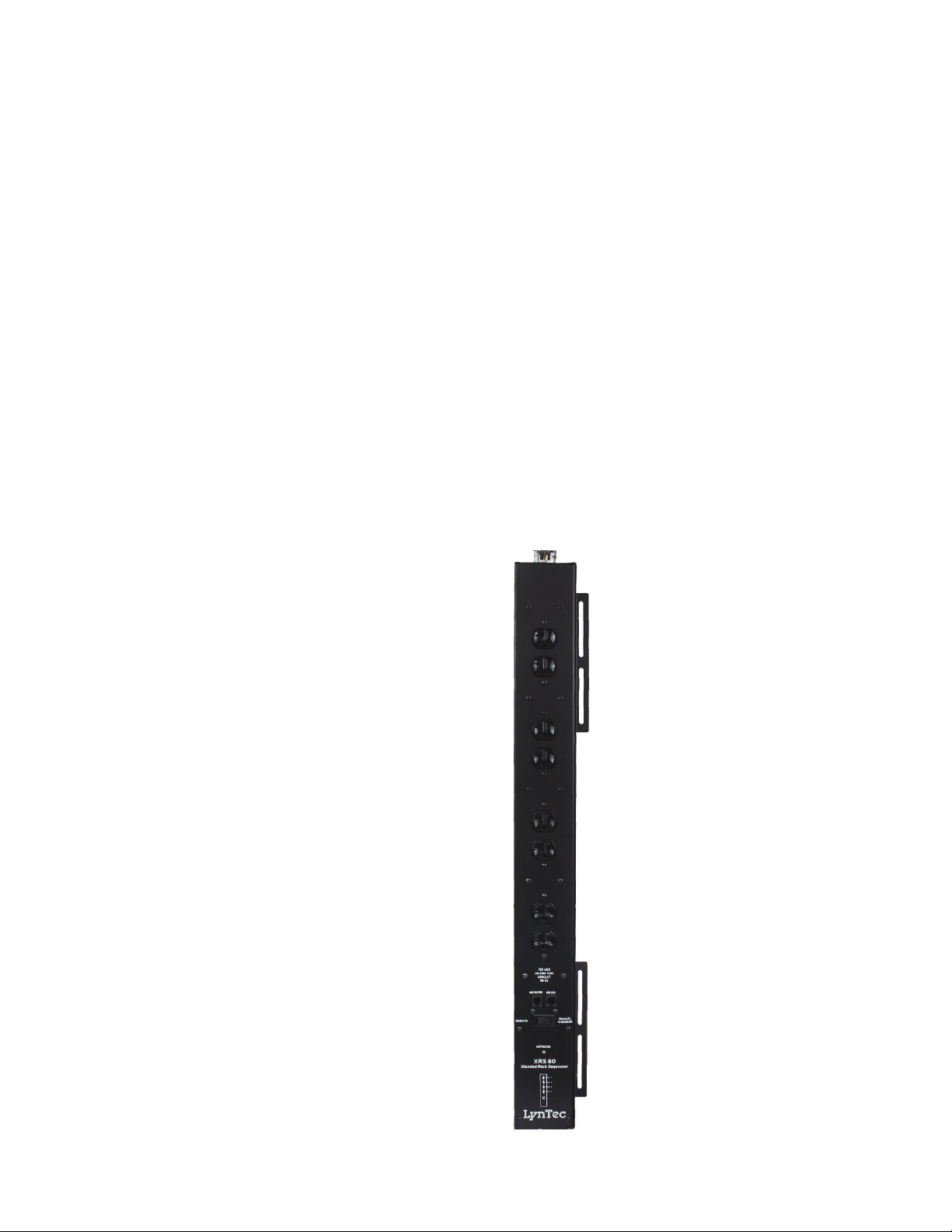
LynTec XPC
Xtend Power Control Series
Instruction Bulletin
Retain for future use.
XRS-80
WEB CONTROLLED
AC POWER DISTRIBUTION
139-0672-00 10/30/18
Page 2
HAZARD CATEGORIES AND
SPECIAL SYMBOLS
Read these instructions carefully and look at the equipment to become familiar
with the device before trying to install, operate, service, or maintain it. The
following special messages may appear throughout this bulletin or on the
equipment to warn of potential hazards or to call attention to information that
clarifies or simplifies a procedure.
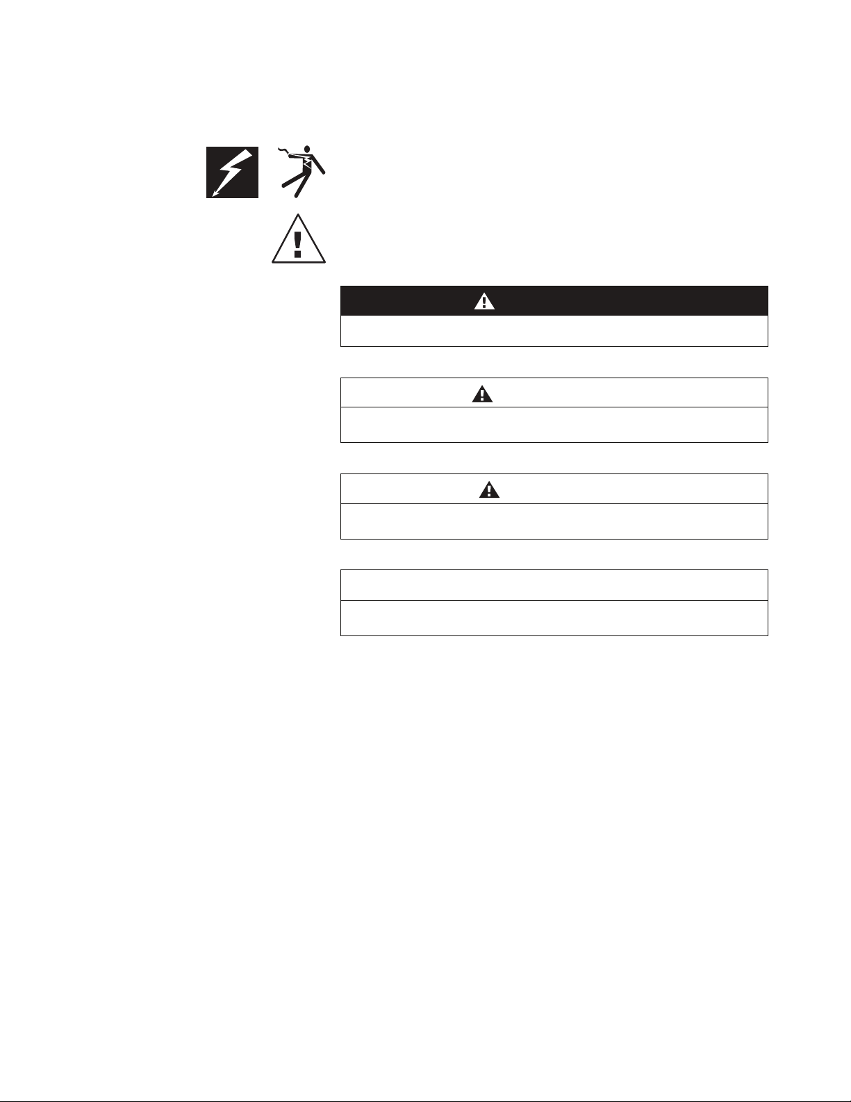
The addition of either symbol to a “Danger” or “Warning” safety label indicates
that an electrical hazard exists which will result in personal injury if the
instructions are not followed.
This is the safety alert symbol. It is used to alert you to potential personal injury
hazards. Obey all safety messages that follow this symbol to avoid possible
injury or death.
DANGER
DANGER indicates an immediately hazardous situation which, if not
avoided, will result in death or serious injury.
WARNING
WARNING indicates a potentially hazardous situation which, if not
avoided, can result in death or serious injury.
PLEASE NOTE
CAUTION
CAUTION indicates a potentially hazardous situation which, if not
avoided, can result in minor or moderate injury.
CAUTION
CAUTION, used without the safety alert symbol, indicates a potentially
hazardous situation which, if not avoided, can result in property damage.
NOTE: Provides additional information to clarify or simplify a procedure.
Electrical equipment should be installed, operated, serviced and
Electrical equipment should be installed, operated, serviced, and maintained
only by qualified electrical personnel. This document is not intended as an
maintained only by qualified electrical personnel. This document is not
instruction manual for untrained persons. No responsibility is assumed by
intended as an instruction manual for untrained persons. No responsibility
Square D for any consequences arising out of the use of this manual.
is assumed by LynTec for any consequences arising out of the use of this
manual.
Page 3

Table of Contents
Contents
Chapter 1--Introduction .........................................................................................................................................................4
OVERVIEW ........................................................................................................................................................................4
Safety Precautions ...........................................................................................................................................................4
Disclaimer .........................................................................................................................................................................4
Chapter Two--Quick Start Guide ..........................................................................................................................................5
Chapter 3--Detailed ...............................................................................................................................................................6
Installation and Setup ............................................................................................................................................................6
Setup Detail ......................................................................................................................................................................6
Connecting to the XRS-80 with a Router .............................................................................................................. 6
Connecting to the XRS-80 using a Crossover CAT5/6 cable ............................................................................. 7
Management ....................................................................................................................................................................8
Overview Tab ..............................................................................................................................................................8
Network Tab ...............................................................................................................................................................9
Chapter Four--Troubleshooting .......................................................................................................................................... 10
Troubleshooting ............................................................................................................................................................. 10
Detail Specifi cations.............................................................................................................................................................. 11
139-0672-00.3 3
Page 4

Chapter One--Overview
Introduction
Chapter 1--Introduction
OVERVIEW
SAFETY PRECAUTIONS
The LynTec XRS-80 is a microcontroller based power
distribution device that can be accessed via Internet or
intranet communications using an Ethernet connection.
With this remote access, individual AC circuits can be turned
on and off and AC power receptacles can be monitored for
electrical current fl ow.
The XRS-80 has four 20 amp capacity circuits.
The XRS-80 is designed to operate at 120 volts, 60 hertz.
Operation with any voltage or frequency other than that can
damage the equipment and create an unsafe situation.
CAUTION #1: This device must be grounded.
CAUTION #2: This device should be installed only by
qualifi ed electrical technicians using appropriate mounting
hardware and correct installation techniques. Before
installing make sure main power is off.
DISCLAIMER
CAUTION #3: Do not expose this product to moisture or
salty air. Doing so could cause signifi cant damage and
create an unsafe condition.
LynTec shall under no circumstances be held responsible for
any losses, damage, or injury resulting directly or indirectly
from the use of the XRS-80 device in a manner contrary
to accepted safe operating methods or any instructions
contained in this document. The user should determine prior
to use whether this product is adequate, suitable and safe for
the application intended. Since individual applications can be
subject to extreme variation LynTec makes no representation
or guarantee as to the suitability of the XRS-80 for any
generally described application.
139-0672-00.44
Page 5

Chapter Two--Quick Start Guide
1. Unbox the unit. The box should contain: XRS-80 device
and user manual QR. You will need to have the XRS-80
hard wired installed by a qualifi ed electrician. Y ou will
need a CAT5 network cable if attaching to a router, a CAT
5/6 crossover cable if connecting directly to a PC. Apply
power to circuit #1.
2. With your PC/laptop on and booted up, connect the
XRS-80 to your router or directly to a PC/laptop using a
suitable cable. If the XRS-80 is connected to a network
router use a standard CAT 5 cable, if connected directly to
a PC/laptop use a CAT 5/6 crossover cable.
Chapter To--Quick Start Guide
3. The XRS-80 will take about 30 seconds to boot up and
confi gure itself at which point the Network light on the
front of the unit will illuminate, indi-cating network
connectivity. If the Network light blinks or does not light at
all check the cable connections.
4. Open up your web browser and type in the
following default IP address to access the XRS-80:
http://192.168.1.250
5. At this point you will be prompted to log into the XRS-80.
Initial login:
Username: admin
Password: pw
6. Use the “Network Setup” page to set a specifi c static IP
address for your installation.
7. See your system administrator, if you have one, for help
with confi guration.
139-0672-00.5 5
Page 6

Chapter Three--Detailed Installation & Setup
Chapter 3--Detailed
Installation and Setup
SETUP DETAIL
Connecting to the XRS-80
with a Router
Unbox the unit. The box should contain: XRS-80 device and
user manual QR. You will need to have the XRS-80 hard
wired installed by a qualifi ed electrician.
1. Apply power to circuit #1.
2. Connect the XRS-80 to your network router using a Cat 5
cable plugged into the RJ45 “Network” port on the front
of the unit and the other end to your network router.
3. The XRS-80 will take a few seconds to boot up and
confi gure itself at which point the Network light on the
front of the unit should illuminate and remain on without
blinking, indicating network connectivity. If the Network
light blinks check the cable connections.
4. Open a web browser on your PC or Laptop and type in
the following address on the navigation bar to access the
XRS-80: http://192.168.1.250 Be sure to type exactly as
shown. No domain such as “.com” should be added.
5. You will be presented with the login box. Enter the
following initial username and password:
Initial login:
Username: admin
Password: pw
6
139-0672-006
Page 7

Chapter Three--Detailed Installation & Setup
Connecting to the XRS-80 using
a Crossover CAT5/6 cable
To connect the XRS-80 to a PC or laptop directly you will
need to change the properties of your internet connection/IP
address.
1. Plug the CROSSOVER cable into the PC/laptop
network socket and the other end into the XRS-80
Network socket .
2. The XRS-80 device will take a few seconds to boot up
and confi gure itself at which point the Network light on
the front of the unit should illuminate and remain on
without blinking, indicating network connectivity. If the
Network light blinks check the cable connections.
3. In Windows go to your start menu and navigate to the
control panel. Then choose the Network Connections”
icon.
4. Open Network connections by double clicking on it,
select the LAN or HIGH-SPEED icon, right click on this
and select properties.
5. Click once on the Internet Protocol item that you will
see at the bottom of the list and select the properties
button which is at the mid right.
6. Check the “Use the following IP address” box and then
change the IP address to: 192.168.1.1, then change the
Default Gateway address also to: 192.168.1.1.
7. Click OK and then close the network box.
8. Open a web browser on your PC and type in the
following address on the navigation bar to access the
XRS-80: 192.168.1.250.
9. The XRS-80 login box will appear, enter your login
details and operate the XRS-80.
139-0672-00.7 7
Page 8
Chapter Three--Detailed Installation & Setup
MANAGEMENT
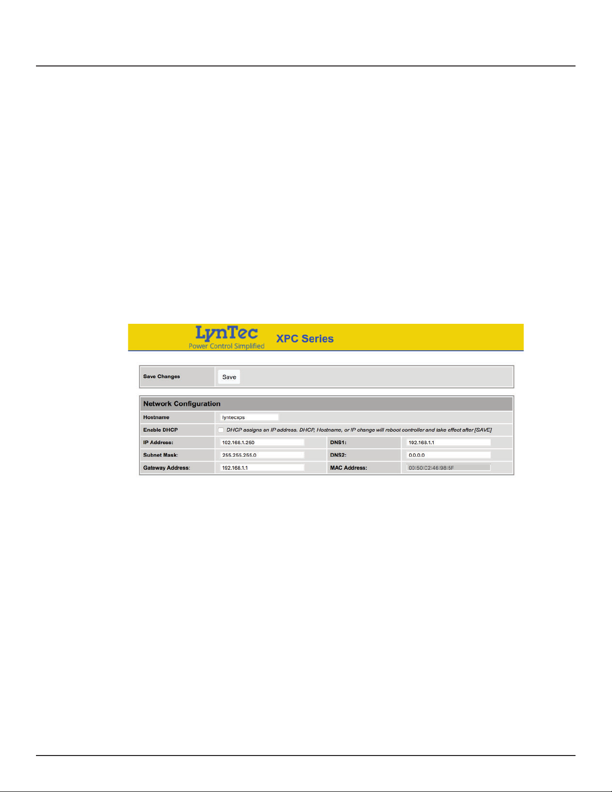
Network Setup
Once you have logged into the XRS-80 you will
see”Network Setup”. You can confi gure the IP address
and other required network settings (dependent on your
personal network)
The Network Setup Page displays the current settings of the
unit and the MAC address. This page is useful for retrieving
all the information you may need to set up the XRS-80 on
your network. Disable DCHP and set a static IP address for the
XRS-80.
8
139-0672-008
Page 9
Chapter Four--Troubleshooting
Chapter Four--Troubleshooting
TROUBLESHOOTING
The LynTec XPS-80 is ruggedly constructed and contains
quality components. There are no user serviceable parts
inside this device. Unauthorized service will void all existing
warranties and may result in equipment damage and
personal injury.
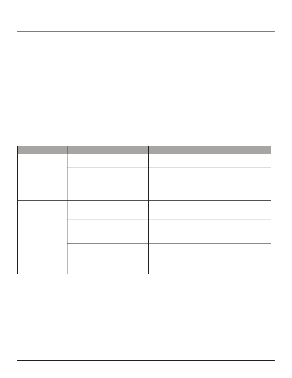
Should improper performance be observed consult the
following guidelines for diagnosis.
Condition Possible Causes Solutions
Verify that the utility provided power for the building is
available.
Check that the circuit breaker for circuit #1 is not tripped.
Reset the circuit breaker by turning it OFF and then back
ON.
Follow above solutions
Check you are using the correct cable, standard CAT5
cable for router connection, crossover cable for direct to
PC connection.
If you are connecting directly to a PC you will have to
confi gure your computer to have a static IP address of
192.168.1.1. See your operating systems help fi le on how to
do this.
Are you using the correct username and password? If
you are accessing the login page and your login is failing
you might need to reset to factory default and try again
if you have forgotten the correct username/password
combination. Contact LynTec for reset instructions
The XRS-80 will not
power up and network
light is not lit.
The XRS-80 will not
power down.
I cannot connect to
the XRS-80 via my
network
Main utility power outage
Tripped breaker(s)
See power up causes above
Incorrect network cable
Incorrect computer IP address
Incorrect username/password
139-0672-00.9 9
Page 10
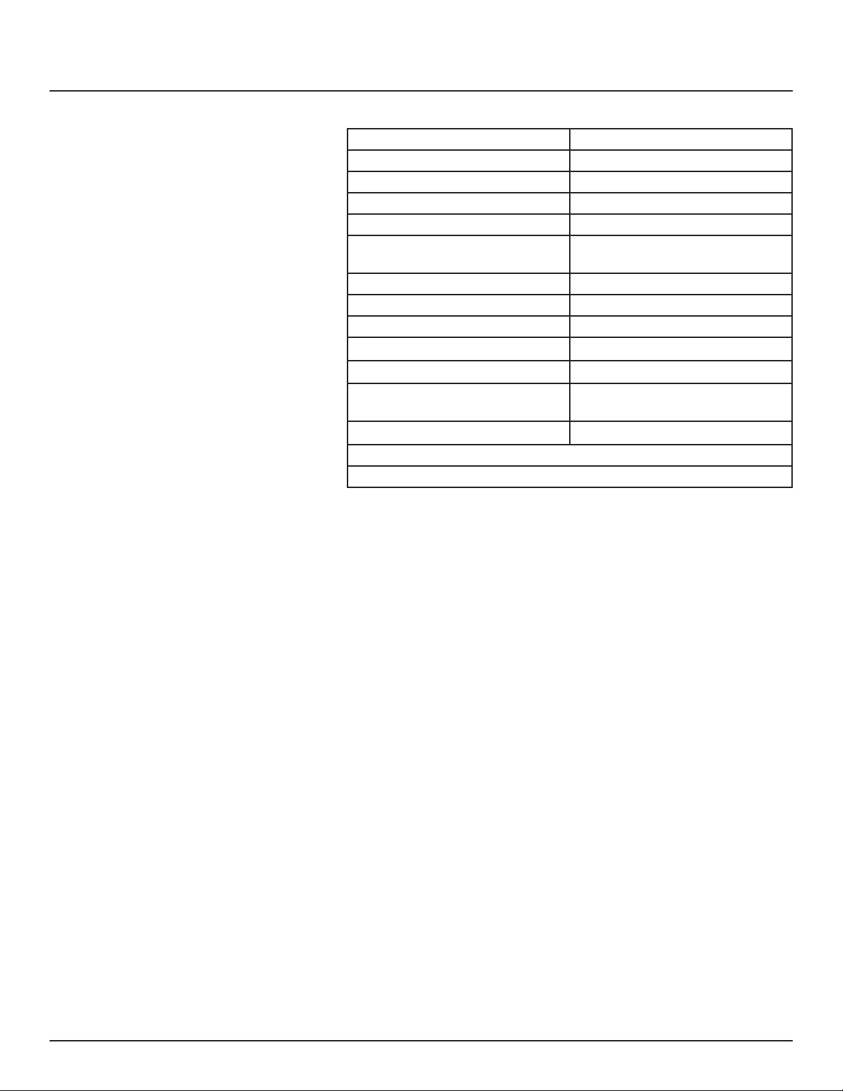
Detail Specifi cations
Detail Specifi cations
Chassis 16 Gauge Steel
Dimensions 32”l x 3.5”w x 2”d
Relay current rating Four @ 30A
Number of circuits Four @20A
Number of controlled Pods Four (one per circuit)
Power input 4’ external wire harness (4 line, 4
neutral, 1 ground)
Power Output Four NEMA 5/20R Duplex
Input Voltage 120 VAC @60Hz
Communications input Ethernet (RJ-45, 8-wire)
Communications Protocol HTML
Front Panel Monitor LED indicates network connection
Front Panel Control Override switch to turn on in event
of product or network fault
Standards UL508A
FCC--Part 15, Class A
ETL Tested to: CU 22.2-14 and UL508A
10
139-0672-00.10
 Loading...