

Page 1
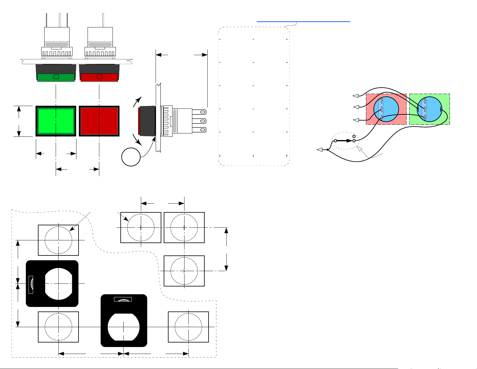
0.710"
idec
12v LED
AL6–M
SOUND SYSTEM
A.C. POWER
ON
FLASHES DURING SEQUENCING
0.930"
SOUND SYSTEM
LynTec.com
OFF
1.00"
idec
AB6–M
A.C. POWER
Switch Specifications:
SPDT momentary
Contacts: 24v @0.7A
LED: 12v AC/DC@ 10ma.
Rock
cap
LynTec.com
while
pulling
outward
to
remove.
Rubber
anti-rotation
gasket
Maximum
Panel
Thickness: .25"
1.25" min.
Custom switch legends you can print on your laser printer
See http://www.lyntec.com/139-0309_CSLF-1_Film.pdf
A partial sample of
custom film legends
OUTSIDE
ONLY
LynTec.com LynTec.com LynTec.com LynTec.com LynTec.com
ON
OUTSIDE
ONLY
OFF
VIDEO SYSTEM
A.C. POWER
ON
POWER AMPS
ONLY
OFF
Power Amplifiers
ONLY
OFF
.770" x .535"
LOWER BOWL
ONLY
ON
LOWER BOWL
ONLY
OFF
PROJECTOR
A.C. POWER
ON
AUTO
MIX
ON
AUTO
MIX
OFF
LynTec.com LynTec.com LynTec.com LynTec.com LynTec.com
To LynTec
PDS, MRTS, MSLC,
SLC, MSP or SP
series sequencer
To FIRST sequencer if daisy chained.
PILOT LED +
To FIRST sequencer if daisy chained.
To LAST sequencer if daisy chained.
COM
See reverse side for multiple switch set wiring.
1
ON
OFF
A.C. Sequencing Systems
Switch set to sequencer: 4 conductors.
Between daisy chained sequencers:
9 conductors, 11 if Power Vouchers are used.
8
shown
3
unlocked
(active)
Up to 2500 ft. run: 24 ga.
2,500 to 3,750 ft. run: 22 ga.
Rear view wiring diagram
NC
NO
C
Optional Key-Lock Switch
SS-2PL Sequencer Switch is a combination of
a SS-2 Switch Set with a KS-2L Locking Switch,
mounted on a single gang stainless steel wall plate.
Mechanical layout on reverse side.
LynTec
Wire requirements
+
ON OFF
NC
NO
C
–
Actual size drill templates
Vertical mounting
1.00"
LOCKED
1.00"
.625" dia. hole. (5/8")
Maximum panel
thickness: .250" (1/4")
SS-2 Switch Set
+
optional KS-2L Locking Switch
with tumbler position label.
.750" x .640" double-D or
.750" dia. hole.
SS-2 Switch Set
LOCKED
1.00"
If mounted vertically, leave this much
space for easy lens cap removal.
Horizontal mounting
1.50" 1.50"
1.00"
LynTec
one
SS-2 Sequencer Switch Set
Up to 5* additional remote
control locations may be
added to the system with
additional switch sets or with
other momentary switches.
139-0252-13.1 SS-2 insert 7/2/09
For SS-32 Switch Sets see
http://www.lyntec.com/139-0396_SS-32_Insert.pdf
Page 2
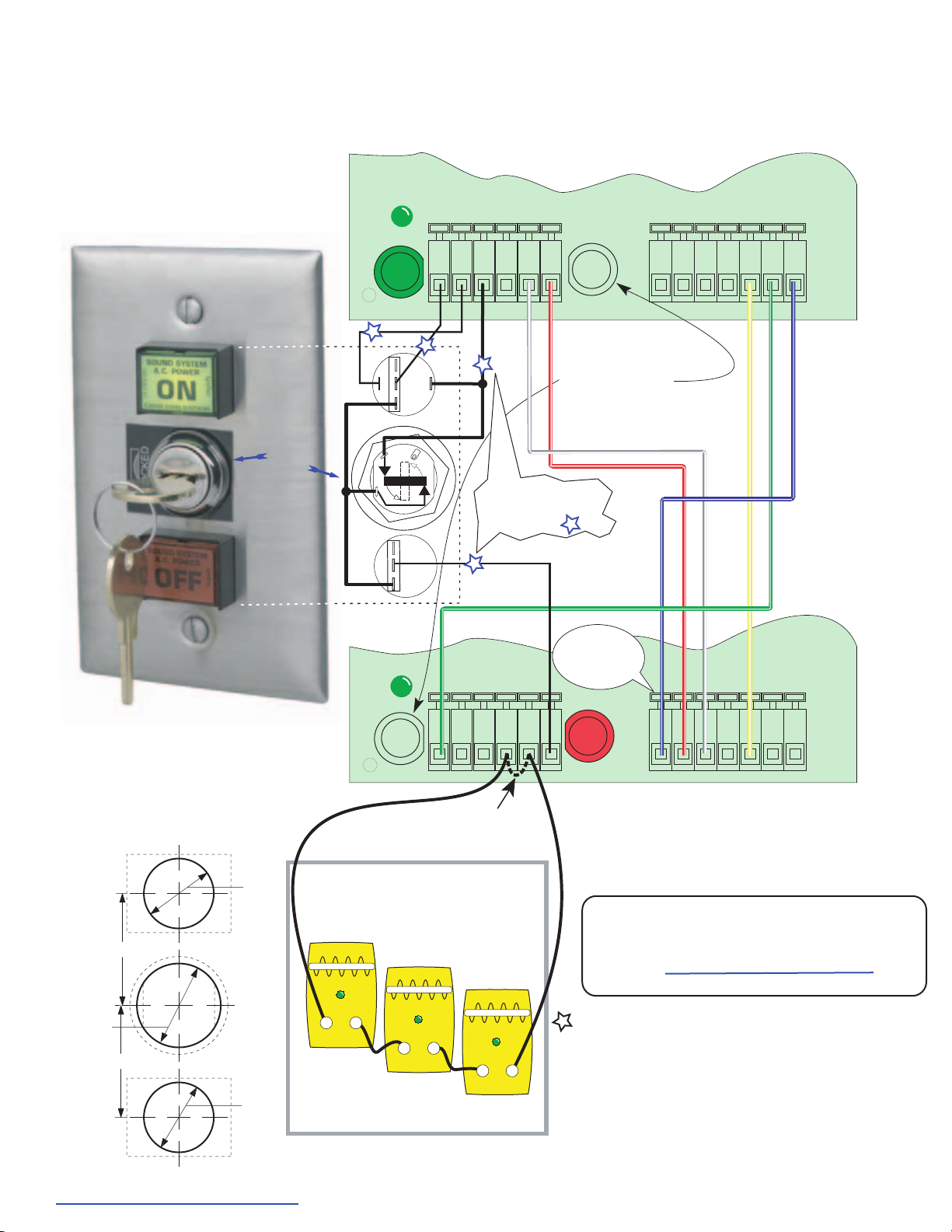
First
Last
For SLC & SP LynTec Power Sequencers (no longer in production)
One set of the ON and
switches shown below are supplied
unmounted as a SS-2 Switch Set with
each LynTec sequencer cabinet.
Mount in 5/8" dia. round holes in panels up
to 1/4" thick.
LynTec
Locking Swich Set.
(Optional)
OFF
Lock
switch
shown in
unlocked
position
Model SS-2PL
Multiple Sequencer Hookup Diagram
Showing Low-Voltage Remote ON/OFF Control
and Daisy-Chain Wiring
PILOT
LED
(green)
ON
Test button
P
NO
Rear connections
P
NC
–
NO
+
C
C
8
C
1
OSLO
3
NC
C
ON
Green
Pilot
P
For multiple control points
add SS-2's or SS-2PL's.
Parallel connect lines.
P
Com
PilotON
V+ V- OFFCom
White
V+ V- OFF
Borrow
Hold
Red
When sequencers
are daisy-chained avoid using
these test switches.
Use the first ON test switch
and the last OFF test switch
to avoid confusing operation.
P
Cage clamp
terminal blocks.
Press white lever
back to insert
stripped wire.
Blue
OFF
Test button
Hold Borrow
Pilot Com CarryCom Busy
Ye l l o w
Red
White
Pilot Com CarryCom Busy
Yellow
Board (Bottom)
First
Sequencer
Board (Top)
Blue
Green
Last
Sequencer
Switch layout for field
constructed panel mounting.
1/4" max. panel thickness.
SS-2
ON
Switch
1.000"
KS-2L
Lock
0.750"
139-0202-11.2 SLC Hookup 3/30/04
See http://ww
Switch
1.000"
SS-2
OFF
Switch
w.lyntec.com/139-0202_SLC_Hookup.pdf for latest
0.625"
0.625"
Install Jumper in LAST sequencer
board only if POWER VOUCHERs
are not installed.
Optional Power Vouchers verify all circuits
are hot and no circuit breakers are tripped.
ON light won't stay lit at end of ON
sequence if any ac circuit fails.
Power Voucher
LynTec
™
LynTec
Model PV-110
Power Voucher
LynTec
™
Power Voucher
LynTec
Power Verification Module
(Optional)
version.
Voice 800-724-4047 or 913-529-2233 • Fax 888-722-4157 or 913-529-4157
Daisy-Chain wiring:
10 conductors max.
(Worst case with multiple switch set locations and
Power Vouchers™ )
See http://www.lyntec.com/139-0252.pdf
for multi-panel daisy chain connections.
™
P
Parallel connect additional SS-2 switch
sets for multiple remote control locations.
4 conductors, 22 ga., 5,000 ft. max.
Maximum number of switch sets:
SLC's & SP's support 6 switch sets.
PDS-8's support 3 switch sets.
LynTec
8401 Melrose Drive • Lenexa, KS 66214 U.S.A.
www.LynTec.com
Page 3
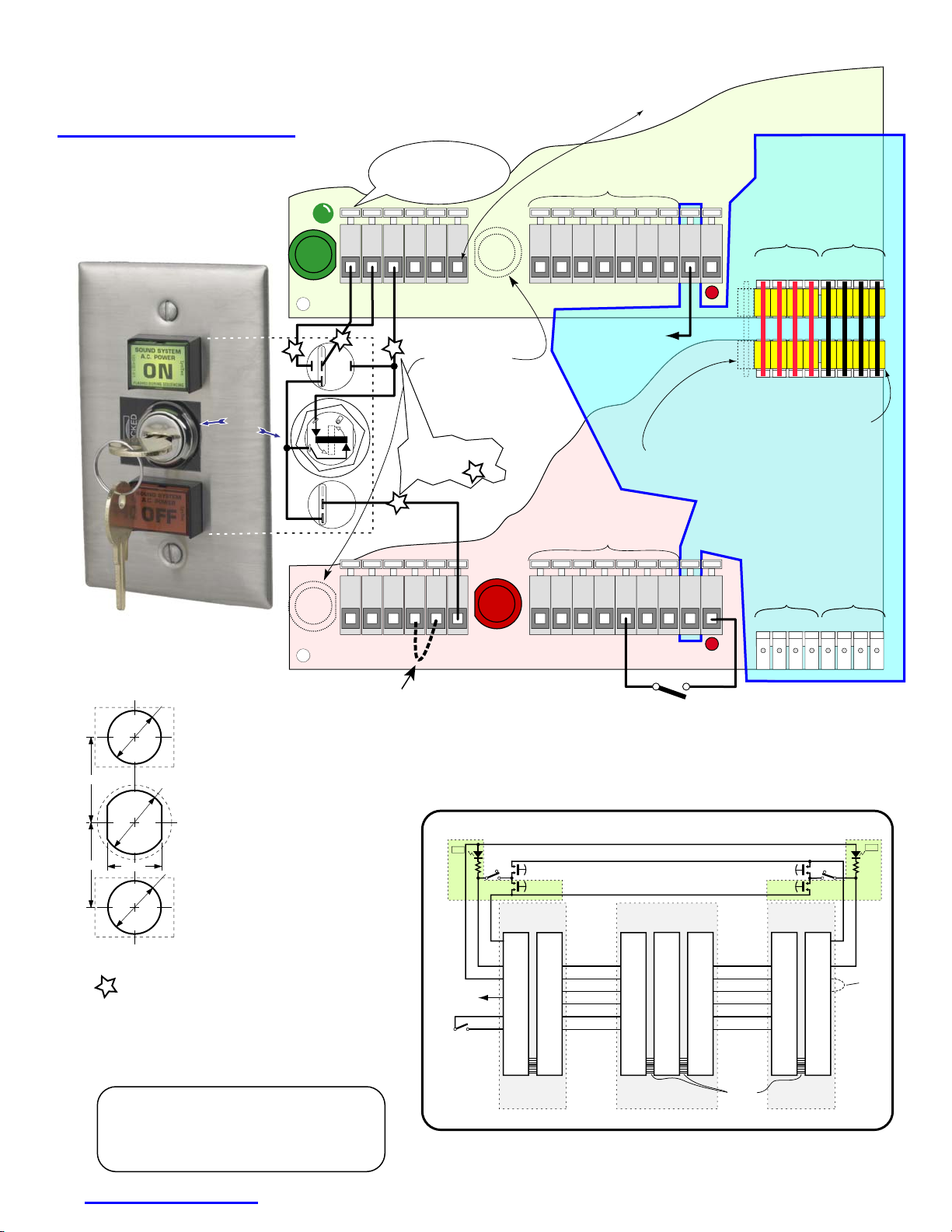
FIRST
LAST
+
+
For LynTec MSLC and MSP MODULAR and PDS series Power Sequencing Products
ON
OFF
Custom switch legends you
can print on your laserprinter
See http://www.lyntec.com/139-0309_CSLF-1_Film.pdf
One set of the ON and
switches shown below are supplied
unmounted as a SS-2 Switch Set with
each LynTec sequencer cabinet.
Mount in 5/8" dia. round holes in panels up
Switch layout for field
constructed panel mounting.
1/4" max. panel thickness.
1.000"
146-0231-08 3/25/05
1.000"
P
Parallel connect additional SS-2 switch
to 1/4" thick.
LynTec
KS-2L
OFF
Model SS-2PL
Locking Swich Set.
(Optional)
0.625"
SS-2
ON
Switch
0.750"
Lock
Switch
0.640"
0.625"
SS-2
Switch
sets for multiple remote control locations.
4 conductors, 24 ga., 5,000 ft. loop max.
Maximum number of switch sets:
All LynTec sequencers support 6 switch sets.
Lenexa, KS (Central time zone) U.S.A.
Voice 800-724-4047 or 913-529-2233
Fax 888-722-4157 or 913-529-4157
139-0252-13.2 SS-2/SS-2PL Insert 7/2/09
See http://www.lyntec.com/139-0252.pdf for latest version.
OFF
Lock
switch
shown in
unlocked
position
LynTec
www.LynTec.com
connections,
rear view
Multiple Sequencer Hookup Diagram
Showing Low-Voltage Remote ON/OFF Control and Daisy-Chain Wiring
For single sequencer board hookup connect OFF switch normally open to OFF.
PILOT
LED
(green)
ON
Cage clamp terminal blocks.
Press white levers back with
small straight-blade screwdriver
to insert stripped wires.
V+ V– OFF
Pilot
ON
Com
Hold
Borrow
These expansion terminals
on the top or middle boards are NOT used
when the cascade connectors are used to
daisy-chain boards within a cabinet.
Pilot Com Carry Com Busy
Test button
+
+5v CMOS Logic output.
P
NC
P
NO
+
1
OSLO
C
–
8
3
NC
NO
When sequencers are
P
daisy-chained avoid using
these test switches.
Use the first ON
and the last OFF
to avoid confusing operation.
For multiple control points
add SS-2's or SS-2PL's.
Parallel connect lines.
P
P
test switch
test switch
C
V+ V– OFF Com
Pilot
ON
Mimics Pilot LED.
3.3KΩ source impedance.
(For touch panel drive)
To isolate the Hurry-Off and Kill functions, unplug left
Power & Kill Connector and move to the left one step,
mis-mating to eliminate the board-to-board Kill connection.
These expansion terminals
on the bottom board are only used
for daisy-chain connections when
more than one cabinet is used.
Pilot Com Carry Com Busy
Borrow
Hold
OFF
+
Install Jumper in LAST sequencer
board only if POWER VOUCHERs
are not installed.
Test button
External contact closure lights the red Kill LEDs and
kills all sequenced power.
Contact opening restarts the ON sequence.
Kill — Fire alarm shutdown
See next page for enlarged daisy-chain hookup
Low voltage control wire: 24 gauge minimum, 5,000 ft. loop max.
A typical three panel, daisy-chained, system with two locking control locations.
+
ON
LED
To touch panel.
(mimics Pilot output)
Fire Alarm
N.O. contact.
Closure kills all
sequenced power.
Opening resumes
ON sequence.
NO
Lock
8
OFF
C
3
1
–
C
ON
NO
TOP
BOARD
BOTTOM
FIRST
ON
Com
Pilot
+5v
Logic
Com
Kill
Cabinet A
Sequencer
boards 1 & 2.
BOARD
Com
V-
OFF
Carry
Busy
Kill
TOP
BOARD
Com
Pilot
Borrow
ON
Hold
Kill
Cabinet B
Sequencer
boards 3, 4 & 5.
For SS-32 Switch Sets see
http://www.lyntec.com/139-0396_SS-32_Insert.pdf
FIRST
Sequencer
Board (Top)
NOT in PDS series
See daisy-chain
connections below
for wiring between
PDS’s or multiple cabinets.
N/C
N/C
Kill
BOTTOM
BOARD
LAST
Cascade
Connector
Busy
Hold
Cascade
Connector
NO
Lock
8
C
3
C
NO
OFF
Com
V+
V-
(4 pin)
Carry
ON
Pilot
(4 pin)
+
–
1
Power & Kill
+5v
Logic Kill
To run each sequencer board as a separate
system, remove the right Cascade Connector.
Connect ON, Pilot, Com & OFF to switch set.
Connector
(4 pin)
24v
AC
Com
24v
Com Kill
AC
LAST
Sequencer
Board (Bottom)
Power & Kill
+5v
Logic Kill
Connector
(4 pin)
OFF
ON
BOTTOM
BOARD
Com
V-
OFF
Carry
Busy
Kill
Daisy-chain
connections
within a
cabinet are
made via
Cascade
Connector.
TOP
BOARD
Com
Pilot
Borrow
ON
Hold
Kill
Cabinet C
Sequencer
boards 6 & 7.
V–
OFF
ON
LED
Connect
V+ to V–
on LAST
sequencer
if Power
Vouchers
are not
used.
Borrow
Page 4
OFF
OFF
C
O
ON
O
–
C
O
ON
+
–
O
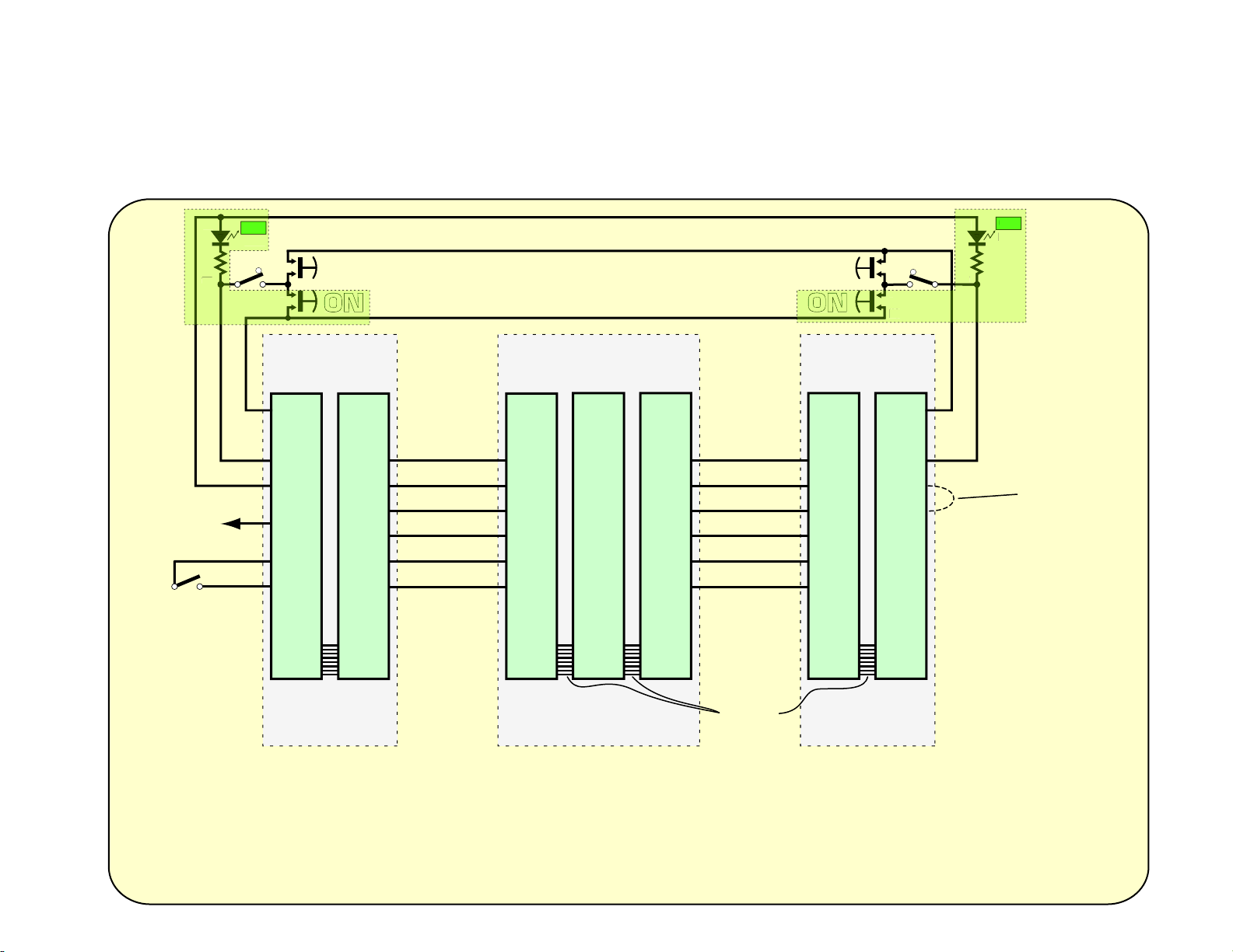
A typical LynTec three panel,
daisy-chained system
with two locking control locations.
For Timing Diagram and Logic levels
See http://www.lyntec.com/139-0266_Seq_Timing.pdf
+
ON
N
LED
NO
Lock
–
8
3
1
NO
N
C
C
OFF
ON
Wire Requirements for Remote Controls
Basic system ON/OFF Control from one panel only....4 conductors
Basic + Kill Add Kill function ....................................6 conductors
2 conductors to Kill control location
Remote control at both ends ............................................9 conductors
Kill, Remote control both ends, full power verification .....11 conductors
Low voltage control wire: 24 gauge minimum, 5,000 ft. loop max.
ON
N
LED
OFF
ON
NO
C
C
NO
N
+
+
Lock
8
3
–
1
To touch panel.
(mimics Pilot output)
Fire Alarm
N.O. contact.
Closure kills all
sequenced power.
Opening resumes
ON sequence.
TOP
BOARD
FIRST
ON
Com
Pilot
+5v
Logic
Com
Kill
BOTTOM
BOARD
Com
OFF
Carry
Busy
Cabinet A
Sequencer
boards 1 & 2.
V-
Kill
BOTTOM
TOP
BOARD
Com
Pilot
Borrow
ON
Hold
Kill
BOTTOM
BOARD
Com
V-
OFF
Carry
Busy
Kill
TOP
BOARD
Com
Pilot
Borrow
ON
Hold
Kill
BOARD
LAST
OFF
Com
V+
V-
Connect
V+ to V–
ONLY on LAST
sequencer if
Power Vouchers
are not used.
Remove factory
Cabinet B
Sequencer
boards 3, 4 & 5.
Daisy-chain
connections
within a
cabinet are
made via
Cascade
Connector
jumper plug.
Cabinet C
Sequencer
boards 6 & 7.
installed V+ to V–
jumpers from the
bottom board of each
daisy-chained cabinet.
V+ to V–
contact-closure keeps
ON led lit at the end of
the on sequence.
139-0252-13.3 Daisy Chain Hookup 7/2/09
Page 5
Built-in Kill, Hurry-Off and ZipOff
for
MSLC and MSP and PDS-8EK series AC SEQUENCING SYSTEMS
What the functions do
(PANIC)
switch option
Kill — EMERGENCY SHUTDOWN
Provides an
sound system at the command of a fire alarm,
emergency announcement system, or ZipOff switch.
IMMEDIATE
shut down method for the
Hurry-Off
The MS-12 Modular & PDS-8EK Sequencing boards
have a new Hurry-Off function. If you
OFF switch for two seconds, a "Kill without restore"
hold down
function is triggered. The system shuts down within 250
Optional ZipOff switch, ZOS-5K
Provides a full AC Power shutdown within 250 milliseconds after the ZipOff button is pushed.
milliseconds and doesn't restart until you give it a new
ON command. Kinda like a DSP undo command.
How they work
In case of a runaway oscillation or other unexpected
signal which could damage the loudspeakers if
sustained...
Lift the protective cov er and press the ZipOff button...
it latches down and lights red. The AC power sequencing system immediately zips off.
Press again to unlatch... the light goes out and the
sequencer restarts to repower the system.
or
Use the new Hurry-Off function at any OFF s witch.
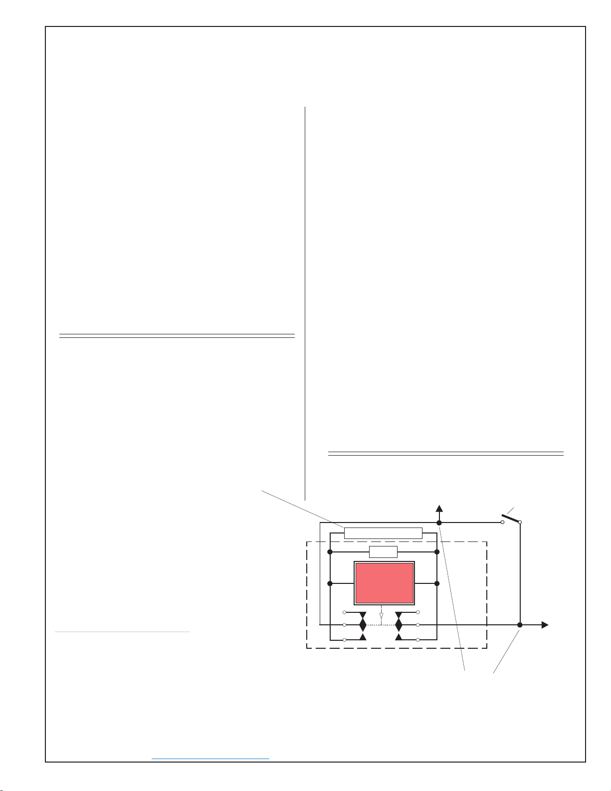
MULTI-BOARD SHUNT R
The Kill line is an 11 ma. current source from each MS-12 Modular
Sequencer or PDS-8 EK board
A voltage sensor on the Kill line determines the Kill threshold.
The Kill line has an open circuit voltage of 28 volts which must be pulled
down to less than 10.5 volts to generate a Kill function. Grounding the Kill
line to Common will always kill the system instantly. This current source may
also be used to light the Zip-Off switch's, red LED.
The red ZipOff LED only requires 10 ma. For systems where multiple-board
system's Kill lines are paralleled, a 9 v. voltage regulator chip is installed in
the ZOS-5K which will automatically shunt the excess source current of up
to 5 boards. For more than 5 boards an additional resistor must be used in
parallel with the ZipOff switch LED. To prevent damage due to overheating
the voltage regulator chip, the resistor should be installed as shown with
length leads
Total Number Shunt Resistor
What to specify or order
to get the heat source away from the switch.
of boards required
1-5........................ none
6 .................... 820Ω, 1/4w
7 .................... 430Ω, 1/4w
8 .................... 270Ω, 1/2w
9 .................... 200Ω, 1/2w
10 ................... 150Ω, 1/2w
11 .................... 150Ω, 1w
12 .................... 120Ω, 1w
13 .................... 100Ω, 1w
14 ..................... 92Ω, 1w
15 ..................... 82Ω, 1w
16............... 75Ω, 2w
17............... 68Ω, 2w
18............... 62Ω, 2w
19............... 56Ω, 2w
20............... 56Ω, 2w
21............... 51Ω, 2w
22............... 47Ω, 2w
23............... 47Ω, 2w
24............... 43Ω, 2w
25............... 39Ω, 2w
☛
full
All LynTec sequencing systems have the ZipOff load
shedding feature. The older SLC, SP and PDS-8's
implemented it by interrupting 24v ac power.
The newer Modular sequencers, the MSLC and MSP
series and the PDS-8EK, load shed when power fails,
but also have a Kill function that is triggered by grounding the Kill line.
The red Kill LED, adjacent to the Kill terminal on the
board, lights and Zip-Off is immediate. The kill line is a
low current line. Long control wiring may be used without
concern for loop resistances up to 32Ω. (22 gauge, up to
a 1,000 ft. run [2,000 ft. loop] or a 680 ft. run of 24 ga).
The ON/OFF
latching
pilot relay remembers that the
sequencer was ON. When the Kill line is opened, the
ON sequence repeats, bringing the AC power back on.
For the Modular series control boards the ZipOff switch
connects the Kill line to common, through the Zip-Off
switch's LED, initiating the Kill function.
To Kill line (all connected within each
cabinet by Power & Kill jumpers) or to
all Kill lines requiring a common kill
function if not daisy-chained.
SHUNT R (for more than 5 boards)
9v voltage
regulator
SOUND SYSTEM
± LED
NC
C
NO
120-6012-03
A.C. POWER
ZipOff
Push to SHUT DOWN.
Push AGAIN to restart sequence.
Push to unlatch
LynTec.com
± LED
NC
CPush to latch
NO
ZOS-5K
ZipOff
Switch
Wiring pictorial
For ZipOff s witch order ZOS-5K. (services up to 5 Kill equipped boards)
Includes switch with ZipOff film legend and flip up security cover.
Switch mounts in 5/8" round hole in panels up to 3/16" thick.
ZOS-5K Contractor C.O.D. price: $40.
Delivery: Stock.
8401 Melrose Drive • Lenexa, KS 66214 • Voice 800-724-4047 or 913-529-2233 • Fax 888-722-4157 or 913-529-4157
www.LynTec.com
on reverse side
For multiple ZipOff
switches connect in
parallel across Kill and
Common.
any
Normally open fire alarm
contact. Close to turnoff
all sequenced circuit
breakers (Kill). Open to
resume power-up
sequence.
To
Common
139-0256-04.1 3/25/04
See
http://www.lyntec.com/139-0256.pdf
for latest version.
Page 6
LynTec
for Modular A.C. Sequencing Systems, models MSLC, MSP & PDS-8EK.
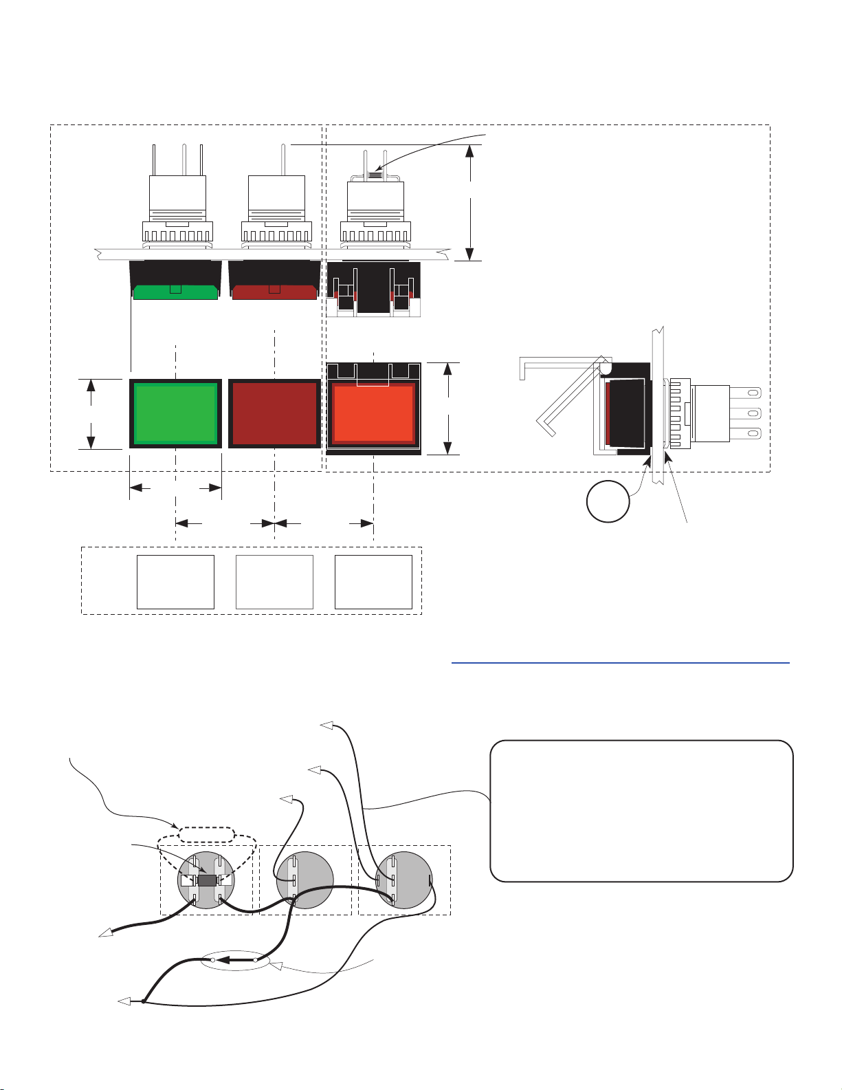
ON, OFF and ZipOff switch mounting & wiring
SS-2
Switch Set
1 set supplied with
each sequencing
system.
0.710"
Film
Legends
12v LED
idec
AL6–M
GREEN
lit when
ON
SOUND SYSTEM
A.C. POWER
ON
FLASHES DURING SEQUENCING
LynTec.com
idec
AB6–M
RED
not illuminated
SOUND SYSTEM
A.C. POWER
OFF
SOUND SYSTEM
LynTec.com
Push AGAIN to restart sequence.
0.930"
SOUND SYSTEM
A.C. POWER
ON
FLASHES DURING SEQUENCING
1.000"
LynTec.com
SOUND SYSTEM
A.C. POWER
OFF
1.000"
SOUND SYSTEM
LynTec.com
Push AGAIN to restart sequence.
Wiring pictorial - Rear view
LynTec
ZOS-5K
146-0259-00
RED
lit when
Zipped Off
A.C. POWER
ZipOff
Press to SHUT DOWN.
A.C. POWER
ZipOff
Press to SHUT DOWN.
LynTec.com
LynTec.com
Voltage regulator
chip for 1 to 5
sequencer boards.
1.171"
Optional
ZOS-5K
ZipOff Switch
includes flip-up security cover
0.930"
Flip-up
security
cover
Rubber
anti-rotation
gasket
.625" dia. hole. (5/8")
Maximum panel thickness: .188" (3/16")
For older PDS-8E series or
SLC, SP series sequencers
see
http://www.lyntec.com/139-0137_ZOS-1.pdf
SHUNT Resistor
required for more than 5
sequencer boards.
See reverse side.
Leave full leads on resistor
to keep heat away from
switch body.
Voltage regulator
chip for 1 to 5
sequencer boards.
To Kill on Modular or PDS-8EK
sequencer board.
See other side for wire sizing
requirements.
(Max. loop resistance: 32).
COM
139-0256-04.2 3/25/04
To PDS-8 EK series or
MSLC, MSP series sequencer
To FIRST sequencer if daisy chained.
To FIRST sequencer if daisy chained.
To LAST sequencer if daisy chained.
SHUNT R
PILOT LED +
OFF
NC
+
NO
–
C
ZipOff
ON
NC
NO
C
NC
–
NO
+
C
ONOFF
Optional Key-Lock Switch
(see SS-2PL Sequencer Switch
with Locking Switch on single gang
stainless steel wall plate)
Wire requirements
Switch set to sequencer: 4 conductors.
Between daisy chained Modular sequencers:
9 conductors, 11 if Power Vouchers are used.
Up to 5,000 ft run: 22 ga.,
5,000 to 7500 ft. run: 20 ga.
7,500 to 10,000 ft. run: 18 ga.
See other side for ZipOff wire sizing.
 Loading...