

Page 1
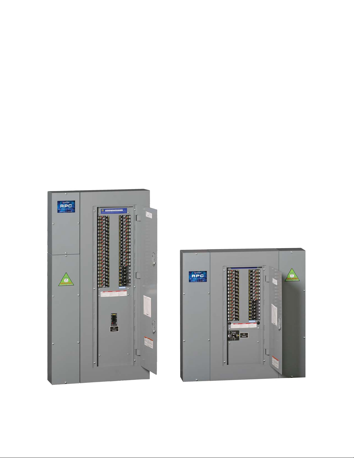
LynTec RPC
Instruction Bulletin
Remote
Power
Controller
Retain for future use.
139-0498-01 2/17/11
Page 2
HAZARD CATEGORIES AND
SPECIAL SYMBOLS
Read these instructions carefully and look at the equipment to become familiar
with the device before trying to install, operate, service, or maintain it. The
following special messages may appear throughout this bulletin or on the
equipment to warn of potential hazards or to call attention to information that
clarifies or simplifies a procedure.
The addition of either symbol to a “Danger” or “Warning” safety label indicates
that an electrical hazard exists which will result in personal injury if the
instructions are not followed.
This is the safety alert symbol. It is used to alert you to potential personal injury
hazards. Obey all safety messages that follow this symbol to avoid possible
injury or death.
DANGER
DANGER indicates an immediately hazardous situation which, if not
avoided, will result in death or serious injury.
WARNING
WARNING indicates a potentially hazardous situation which, if not
avoided, can result in death or serious injury.
PLEASE NOTE
Class A FCC Statement
CAUTION
CAUTION indicates a potentially hazardous situation which, if not
avoided, can result in minor or moderate injury.
CAUTION
CAUTION, used without the safety alert symbol, indicates a potentially
hazardous situation which, if not avoided, can result in property damage.
NOTE: Provides additional information to clarify or simplify a procedure.
Electrical equipment should be installed, operated, serviced and
Electrical equipment should be installed, operated, serviced, and maintained
only by qualified electrical personnel. This document is not intended as an
maintained only by qualified electrical personnel. This document is not
instruction manual for untrained persons. No responsibility is assumed by
intended as an instruction manual for untrained persons. No responsibility
Square D for any consequences arising out of the use of this manual.
is assumed by LynTec for any consequences arising out of the use of this
manual.
This equipment has been tested and found to comply with the limits for a Class
Page 3

RPC Controller
Table of Contents
Contents
Chapter 1--Introduction ....................................................................................................................................................................6
OVERVIEW .......................................................................................................................................................................................6
CONTENTS ......................................................................................................................................................................................6
Controller overview .............................................................................................................................................................7
Chapter Two--Safety Precautions ...............................................................................................................................................10
Chapter Three--Quick Start Guide .............................................................................................................................................. 11
Introduction ................................................................................................................................................................................ 11
Chapter 4--Wiring ............................................................................................................................................................................. 12
Additional Control Options ................................................................................................................................................... 13
Audio Sensing Timer (AST) Wiring: .............................................................................................................................. 16
Analog Input Wiring .......................................................................................................................................................... 16
Emergency Shutdown Wiring: ......................................................................................................................................17
TCP/IP .....................................................................................................................................................................................18
RS-232 .................................................................................................................................................................................... 18
Switch Wiring Instructions .............................................................................................................................................. 19
LynTec SS-2 Switch Set ..................................................................................................................................................... 19
SS-2PL and SS-2LRP Locking Switch Sets .................................................................................................................. 20
Initial Power up procedure .................................................................................................................................................... 23
Chapter 5--Control Setup (Web Page) ...................................................................................................................................... 24
OVERVIEW .................................................................................................................................................................................... 24
Status ............................................................................................................................................................................................ 24
Control ..........................................................................................................................................................................................24
Setup ............................................................................................................................................................................................. 24
Contact ......................................................................................................................................................................................... 24
Voltage ..........................................................................................................................................................................................24
Setup ..................................................................................................................................................................................................... 25
Setup Home ................................................................................................................................................................................ 25
Network setup ................................................................................................................................................................................... 26
NetBios Name ...................................................................................................................................................................... 27
Panel Setup ......................................................................................................................................................................................... 28
Breaker setup .............................................................................................................................................................................. 28
Zone setup ................................................................................................................................................................................... 29
Global Preferences .................................................................................................................................................................... 32
Setup ............................................................................................................................................................................................. 32
Labeling ................................................................................................................................................................................. 32
Numbering and addressing ........................................................................................................................................... 32
Global Control Preferences ............................................................................................................................................. 33
139-0498-01.3 3
Page 4

RPC Controller
Table of Contents
Selecting breakers for Brownout or Emergency Shutdown ............................................................................... 34
Brownout Thresholds .......................................................................................................................................................34
Schedule Setup ................................................................................................................................................................... 35
Assigning Schedules to Zones ...................................................................................................................................... 35
Contact Closure Setup ..................................................................................................................................................... 36
Assigning Contact Closures to Zones ......................................................................................................................... 36
Individual Momentary Contact ON and OFF Pushbuttons ................................................................................. 37
Chapter Six: Operating your RPC ............................................................................................................................................... 38
Using the built-in web page ..........................................................................................................................................38
Using a secondary controller ......................................................................................................................................... 38
Appendix A--RPC Quick Start Guides ........................................................................................................................................39
RPC to RPS Wiring Instructions .....................................................................................................................................39
RPC Quickstart Guide .......................................................................................................................................................41
RPC Contact Closure Wiring Instructions ................................................................................................................. 43
Appendix B--RS-232 and TCP/IP Protocols .............................................................................................................................. 45
RS-232 Protocol..........................................................................................................................................................................45
Addressing Scheme .......................................................................................................................................................... 45
Breaker Related Commands...........................................................................................................................................45
Zone Related Commands ............................................................................................................................................... 47
Event Related Commands ..............................................................................................................................................48
Checksum ............................................................................................................................................................................. 50
TCP/IP Protocol ..........................................................................................................................................................................50
Breaker Control = B ........................................................................................................................................................... 50
Zone Control = Z ................................................................................................................................................................ 50
Events Control = E..............................................................................................................................................................51
Appendix C--Troubleshooting ..................................................................................................................................................... 52
Troubleshooting the controller ............................................................................................................................................ 52
Appendix D--RPC System Components ................................................................................................................................... 54
Control Bus ........................................................................................................................................................................... 55
Remotely Operated .......................................................................................................................................................... 55
Circuit Breakers ................................................................................................................................................................... 55
Power Supply ...................................................................................................................................................................... 56
Bu er ...................................................................................................................................................................................... 56
Transducer ............................................................................................................................................................................ 56
Controller ..............................................................................................................................................................................57
Slave Address Selector ..................................................................................................................................................... 57
139-0498-01.4
Page 5

Introduction
Chapter 1--Introduction
Chapter One--Overview
OVERVIEW
CONTENTS
This bulletin explains how to install and operate the LynTec
Remote Power Controller (RPC). The controller uses remotely
operated circuit breakers to control up to 167 remotely
operated branch circuits. Control signals originate externally
from commands received via the communications network or
from dry contact inputs. Acceptable communications protocols
include TCP/IP, RS-232, and DMX-512. RS-485 optional.
Each RPC comes standard with the following components
installed:
• RPC Controller
• Power Supply
• Capacitive Bu er
• Isolated technical ground
• 15A unmotorized breaker
• Voltage Transducer
Optional additional components include:
• I/O expansion board
• Multi-panel expansion board
139-0498-01.5 5
Page 6
Chapter One--Overview
A
VVVVVV
V
Controller Overview
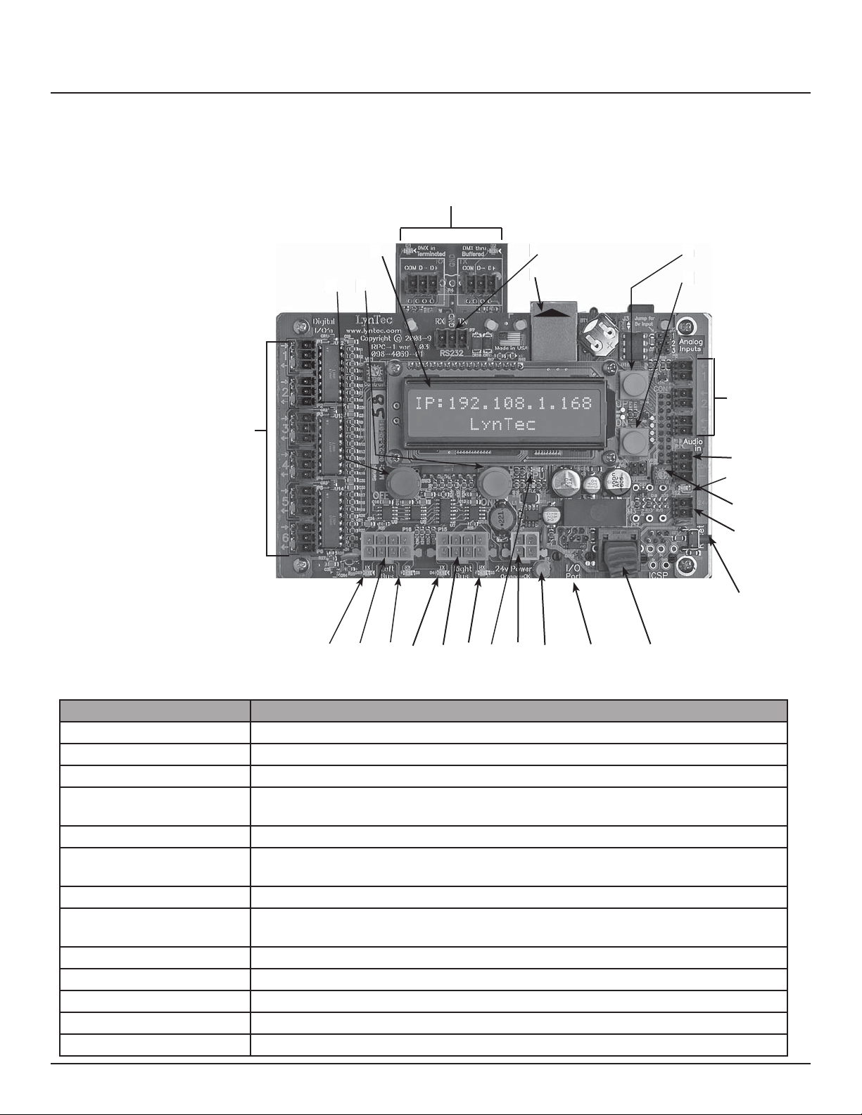
Controller overview Figure 1–1 shows the parts of the RPC controller.
A brief description of each part follows in Table
Figure 1-1: RPC Controller
1–1.
D
A. O Button (Red)
B. On Button (Green)
E
C. LCD Screen
D. DMX Input and Thru
E. RS-232 Port
F. Ethernet Port
G. Menu Up Button
H. Menu Down Button
I. Analog Inputs
J. AST Input
K. Audio Signal Indicator
L. AST Sensitivity Potentiometer
M. Auxiliary Power Output
N. Reset Button
O. MPE Board Port
P. I/O Board Port
Q. Power LED
R. Power Supply Input
S. CPU LED
T. Right RX LED
U. Right Control Bus Port
V. Right TX LED
W. Left RX LED
X. Left Control Bus Port
Y. Left TX LED
Z. Digital I/O Ports
Z
C
B
A
V
WXY
E
F
TCP/IP
Network
connect
G
H
I
J
K
L
M
N
STUV
R
OPQ
Table 1-1: Parts of the RPC Controller
Component Description
A. OFF Button Turns all breakers o
B. ON Button Turns all breakers on
C. LCD Screen Screen shows the IP address, time and setup information.
D. DMX Input and Thru Allow the panel to be directed by a secondary DMX controller. When DMX is enabled, the
control page is disabled.
E. RS-232 Port Control Port for secondary controller such as AMX or Crestron.
F. Ethernet Port Connects the panel to a computer or network for initial setup or long-term operation us-
ing the built-in web interface.
G. Menu Up Button (yellow) Scrolls the screen up.
H. Menu Down Button (yellow)
I. Analog Inputs Additional analog inputs to connect voltage/current monitors or light sensors.
J. AST Input Connects to the Audio Sensing Timer
K. Audio Signal Indicator Flashes when audio signal is present.
L. AST Sensitivity Pot Sets the sensitivity of the Audio Sensing Timer
M. Auxiliary Power Output Auxiliary 24V power for accessories.
Scrolls the screen down.
139-0498-01.66
Page 7
Chapter One--Overview
Controller Overview
Table 1-1: Parts of the RPC Controller
Component Description
N. Reset Button Resets the controller.
O. MPE Port Connects the Multi Panel Expander Board (for use with up to 3 slave panels)
P. I/O Board Port Connects additional I/O boards to the controller. Up to two boards can be added for a
total of 38 contact closure inputs.
Q. Power Led Illuminates when the controller is receiving power.
R. Power Supply Input Connects the controller to the power supply.
S. CPU LED CPU Heartbeat
T. Right RX LED Flashes when the controller is receiving data from the right control bus.
U. Right Control Bus Port Connects the controller to the right control bus.
V. Right TX LED Flashes when the controller is transmitting data to the right control bus.
W. Left RX LED Flashes when the controller is receiving data from the left control bus.
X. Left Control Bus Port Connects the controller to the right control bus.
Y. Left TX LED Flashes when the controller is transmitting data to the right control bus.
Z. Digital I/O Ports Contact closure input, indicator output, and 24VDC common
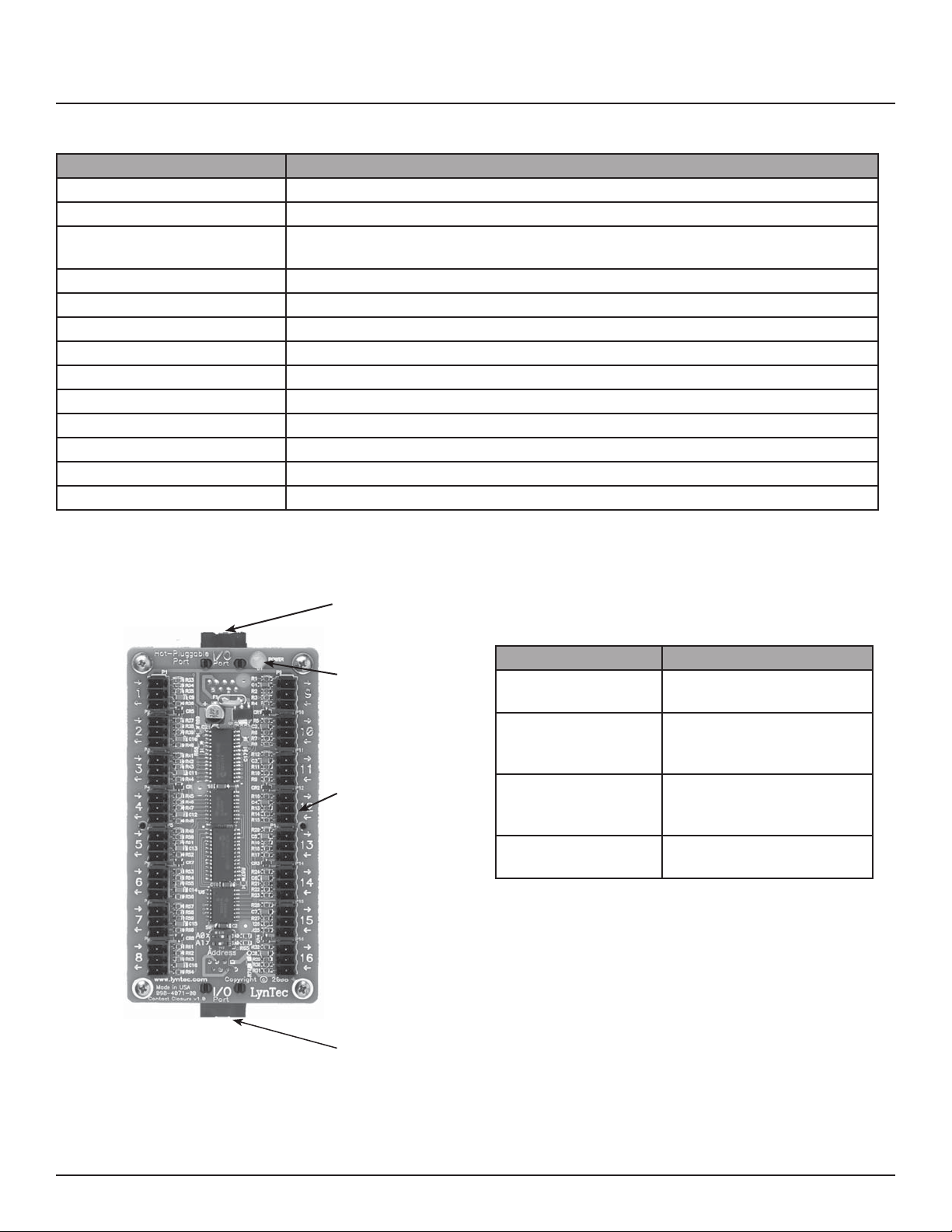
Figure 1-2: I/O Expander Board Figure 1–2 shows the parts of the I/O Board. A
brief description of each part follows in Table 1–2.
A
Table 1-2: Parts of the I/O Board
Component Description
B
C
A. I/O Control Port Connects the board to the
controller.
B. Power LED The power LED is always on
when the board is receiving
power.
C. Digital I/O Headers Allows the panel to be
controlled by contact closure
devices.
D. I/O Control Port
Thru
Connects to an additional I/O
expander board.
D
139-0498-01.7 7
Page 8
Chapter One--Overview
Additional Boards Overview
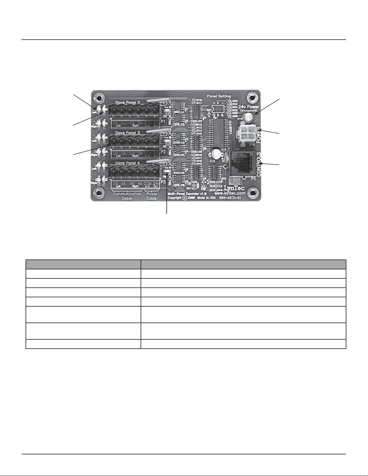
Figure 1-3: Multi-Panel Expander Board Figure 1–3 shows the parts of the additional slave
board. A brief description of each part follows in
Table 1–3.
E
A
F
B
G
C
D
Table 1-3: Parts of the Multi-Panel Expander Board
Component Description
A. Power LED The power LED is always orange when the board is receiving power.
B. Power Input Provides power to control busses on panels two, three and four.
C. Control Input Receives control signal from control board.
D. Control Bus Indicator Indicates that the control busses on panel two, three or four have power.
E. Data transmission indicator Indicates that the Multi-Panel expander board is transmitting data to a
particular control bus (example: panel 2 left).
F. Data reception indicator. Indicates that the Multi-Panel Expander Board is receiving data from a particular
control bus (example: panel 2 left)
G. Expansion Ports Connects the MPE board to control busses on panels two, three and four.
139-0498-01.88
Page 9
Chapter Two--Safety Precautions
This chapter contains important safety precautions that must
be followed before attempting to install, service, or maintain
electrical equipment. Carefully read and follow the safety
precautions below.
Chapter Two--Safety Precautions
!
HAZARD OF ELECTRIC SHOCK, EXPLOSION, OR ARC FLASH
• This equipment must be installed and serviced only by
quali ed electrical personnel.
• Apply appropriate personal protective equipment (PPE) and
follow safe electrical work practices. See NFPA 70E.
• Turn o all power supplying this equipment before working
on or inside equipment.
• Always use a properly rated voltage sensing device to
con rm that power is o .
• Replace all devices, doors, and covers before turning on
power to this equipment.
• Before energizing panelboard, all unused spaces must be
lled with blank llers.
Failure to follow this instruction will result in death or
DANGER
serious injury.
139-0498-01.9 9
Page 10
Chapter Three--Quick Start Guide
Chapter Three--Quick Start Guide
INTRODUCTION
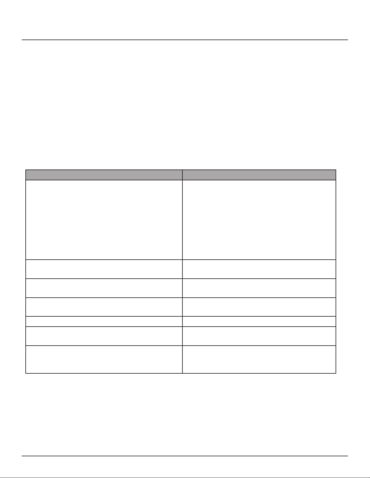
Steps Reference
1. Install all the RPC components according to
their instruction bulletins. Typical components
include, but are not limited to, the following:
• circuit breakers
• controller
• control bus
• power supply
• voltage transducer
• slave address selectors
2. Wire all RPC components according to their
instruction bulletins.
This chapter is a quick reference listing the steps necessary to
install the RPC system. The steps in this chapter are provided as
an installation checklist. For complete installation instructions,
refer the chapter listed.
See appropriate instruction bulletins.
Chapter 4--Wiring
See appropriate instruction bulletins.
3. Connect the controller to a computer or
network for panel setup.
4. Access the web page by entering the IP address
or NetBIOS name into web browser.
5. Complete the panel setup. Chapter 5--Control Setup
6. Connect the controller to a secondary
controller or add contact closures if necessary.
7. If your RPC system does not operate as
expected, verify that everything is installed and
programmed correctly.
Chapter 4--Wiring
Chapter 5--Control Setup
Chapter 4--Wiring
Chapter 5--Control Setup
Appendix A--Troubleshooting
10
139-0498-01.10
Page 11
Chapter Four--Wiring
Chapter 4--Wiring
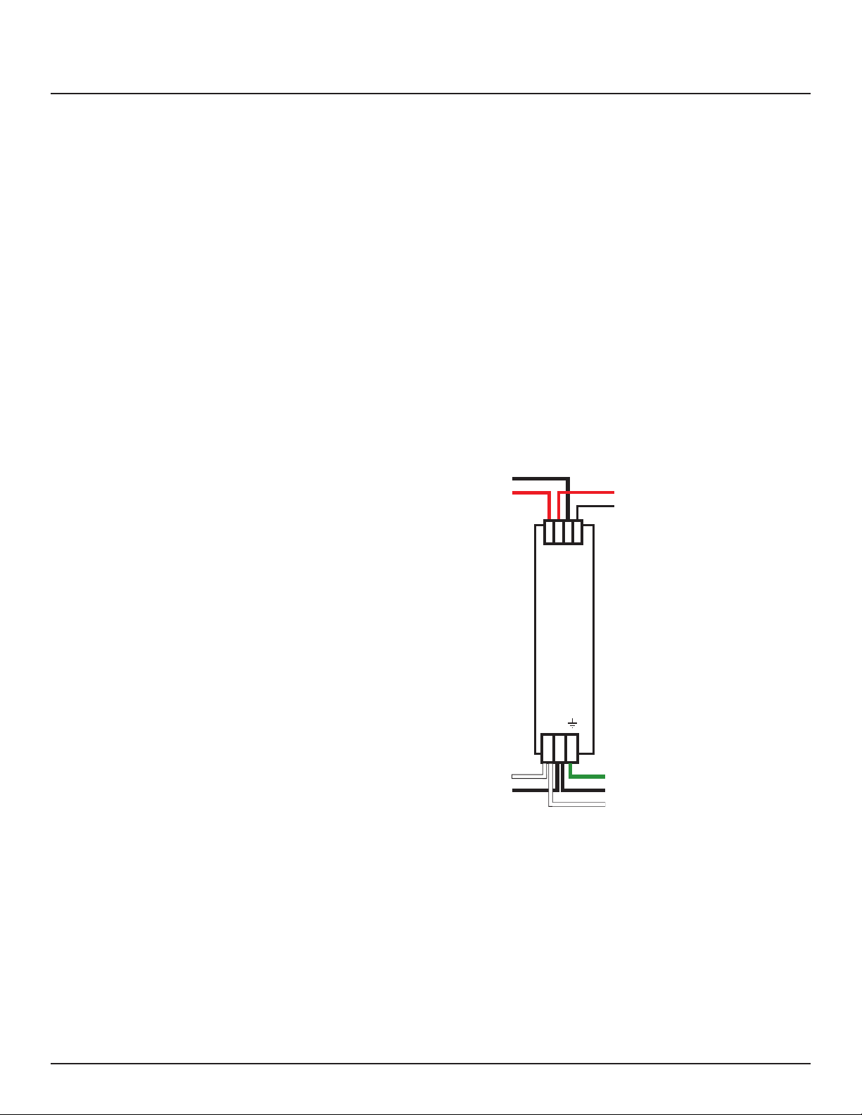
Figure 4-1: Power Supply
To initially wire the RPC follow these easy steps:
1. Install and connect all main and neutral feeds as per NEC.
2. Install and connect the Isolated Technical Ground feed from
the star ground of the isolation transformer or the tie point
from a ground rod or building steel to the Isolated Technical
Ground bar in the ITG sidecar.
3. Ensure all breakers are properly installed in the panel and
that the motorized breakers are rmly plugged into the
adjacent control busses.
Power Supply DC –
Power Supply DC +
Controller Cable
Controller Cable
+ + – –
N L
Transducer Neutral
Transducer Load
Panel Ground Bar
15A Breaker in Panel
Panel Neutral Bus
Steps four, ve and six are completed at the factory. The
instructions are included as a reference only.
4. Connect the black 14 AWG wire from the Load terminal of
the Power Supply unit (Figure 4-1--located at the top of the
Isolated Technical Ground sidecar) to the 15 Amp Controller
Power breaker in the panel.
5. Connect the white 14 AWG wire from the Neutral terminal
of the Power Supply unit to the neutral bus located below
the breakers in the panel.
139-0498-01.11 11
Page 12
Chapter Four--Wiring
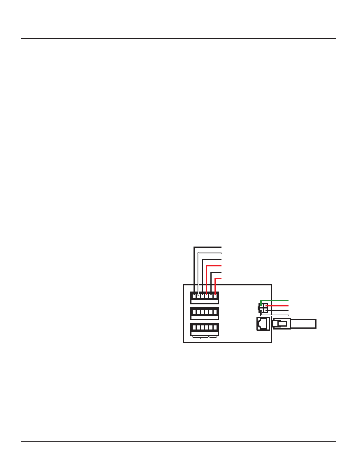
6. Connect the green 14 AWG wire from the ground terminal of
the Power Supply unit to the ground bar attached directly to
the panel interior (DO NOT attach to the isolated technical
ground in the sidecar).
7. Install and connect all load, neutral and Isolated Technical
Ground feeds to circuits.
8. Ensure that all bolts and lug connections in the panel
are tight. Check both sides of the main breaker, the bars
connecting the busses to the main and all breaker retaining
bolts.
9. Check the cable connections at the top of the breaker control
busses to ensure the connectors are properly seated.
10. Replace the dead front pan and cover with door.
ADDITIONAL CONTROL
OPTIONS
Figure 4-1: Multi Panel Expander
Additional circuit boards may be used to add additional panels or
I/O inputs.
Slave Panel 2
Slave Panel 3
Slave Panel 4
Communication Power
Powe r
Controls
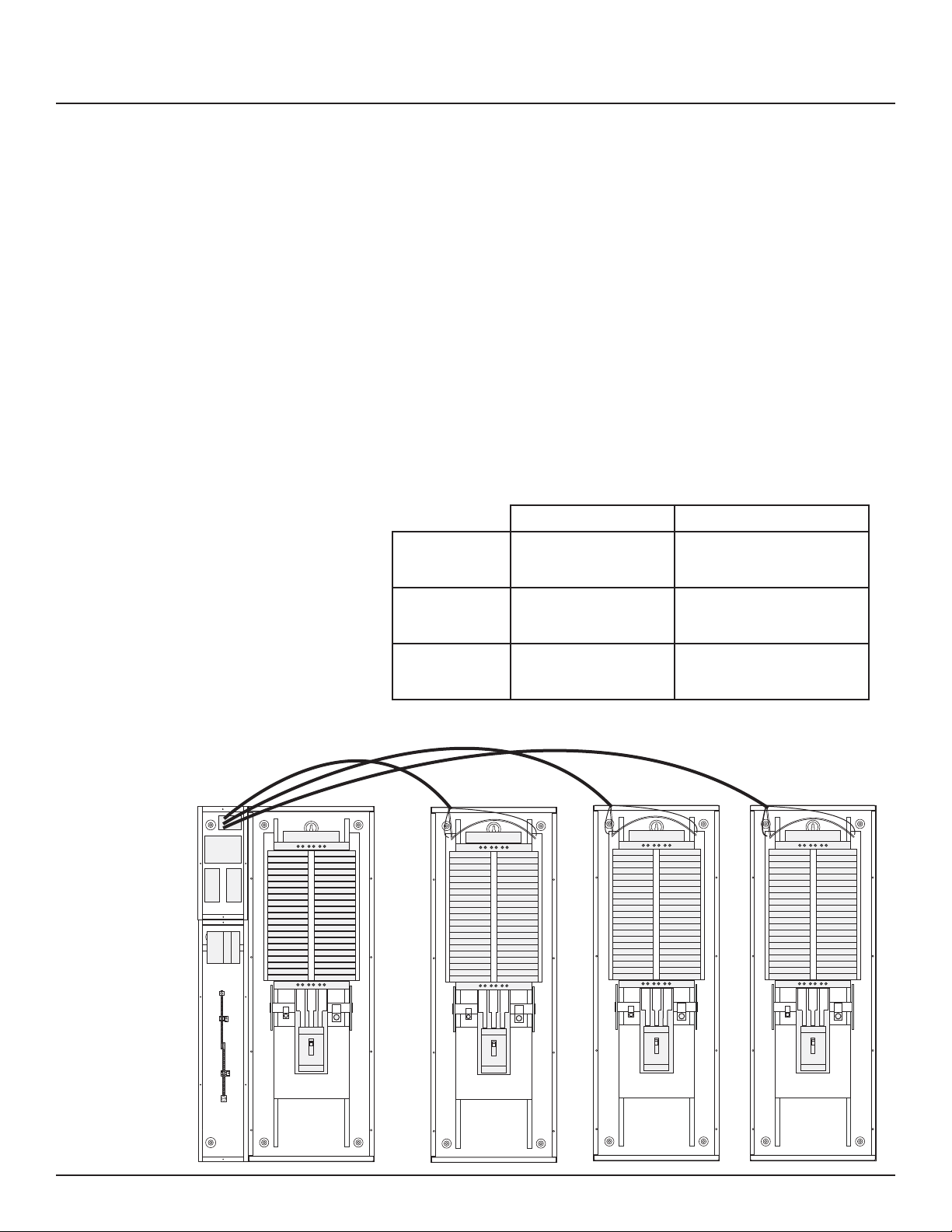
1. If RPS Slave panels are being used in conjunction with an
RPC Master panel, install and connect one 18 AWG six (6)
conductor (Belden 27600 A or equivalent) or two 18-24 AWG
twisted pairs for data and one 16-18 AWG for power per RPS
unit. Terminate the Left Bus B, Left Bus A, Right Bus B, Right
Bus A, Common (–) and 24VDC (+) in the screw-terminal
header for that RPS (Slave Panel 2 – 4) from left to right.
12
139-0498-0112
Page 13
Chapter Four--Wiring
2. At the RPS Slave panels, strip the cable sheath back
approximately 20 inches. Cut the conductors for Left Bus
B, Left Bus A, – and + down to approximately 4 inches and
terminate them in the Left Bus screw-terminal header from
left to right. Terminate the remaining two conductors in
the Right Bus B and Right Bus A positions of the Right Bus
screw-terminal header.
3. Using two cut lengths of 18 AWG wire, install jumpers from
Left Bus – and + to Right Bus – and +. Right Bus will not
operate without these jumpers installed to provide 24VDC
power and common.
4. Set the slave address selectors as follows:
Table 4-2
Master Panel
Left Control Bus Right Control Bus
Panel #2 2 3
Panel #3 4 5
Panel #4 6 7
Slave Panel 2 Slave Panel 3 Slave Panel 4
139-0498-01.13 13
Page 14
Chapter Four--Wiring
Figure 4-3: Digital I/O Remote Switch
and Sensor Wiring
RJ-25 6P6C Flat Cable
to I/O Port on Controller
24 VDC LED
I/O Port
1
2
3
4
5
6
7
8
OUT
24V
IN
I/O Port
RJ-25 6P6C Flat Cable
to next I/O Board
9
10
11
12
13
14
15
16
Indicator
24 VDC LED
Indicator
Momentary ON
Contact Switch
Momentary OFF
Contact Switch
Maintained
Contact Switch
Light Sensor for
Zone Control
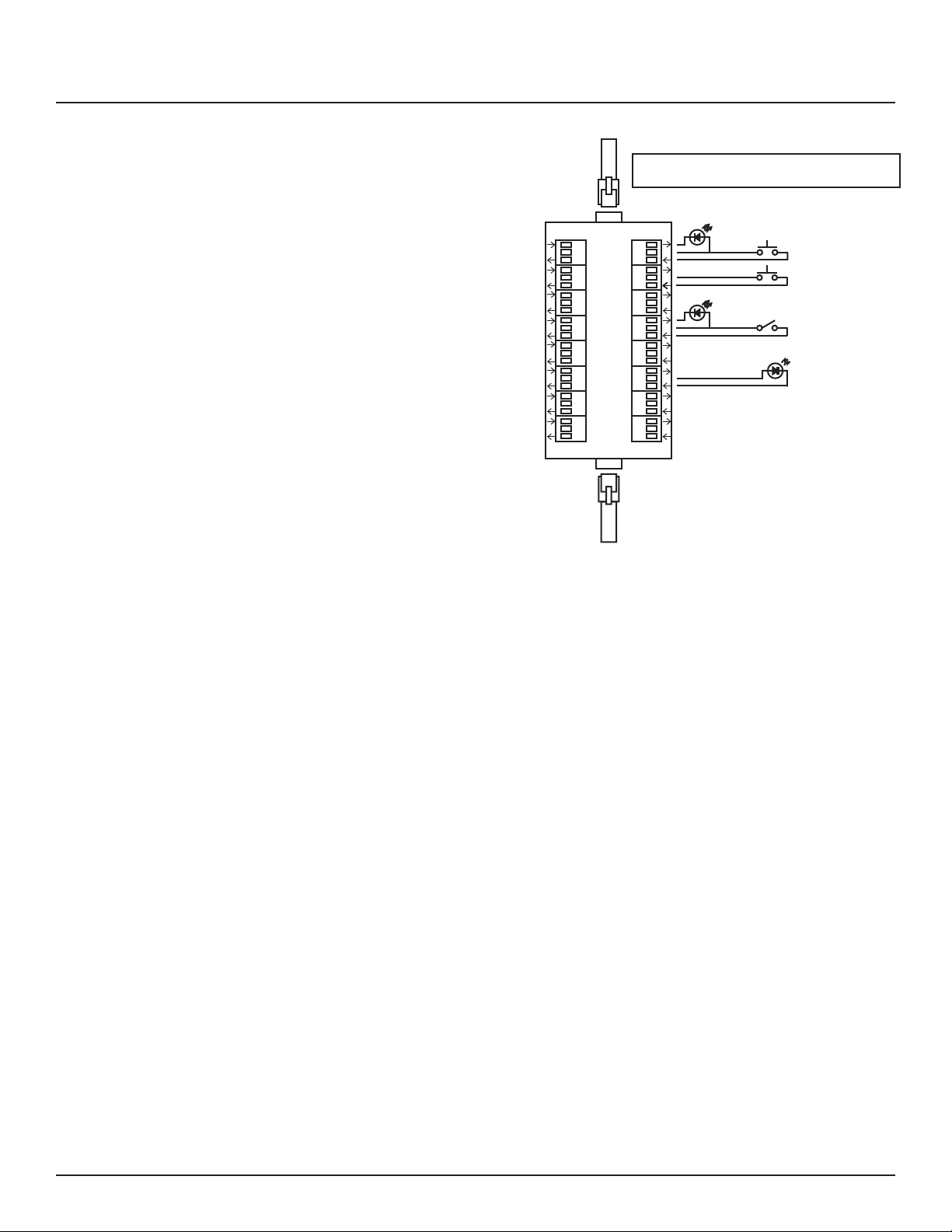
Switches or sensors being used to control either sequenced
or grouped zones are to be connected to the Digital I/O threeposition spring-clamp headers. Each header can accommodate
one input device (switch, sensor, relay) and one output device
(indicator) maximum.
The center terminal of each Digital I/O header is used as a 24VDC
source. The input terminal is triggered when connected through
a remote device to the 24VDC source. The output terminal
activates a remote device by pulling down from 24VDC to 0VDC
and creating current ow.
To assign both an On and O function for one zone would
require two input terminals and occupy two I/O headers. Six (6)
Digital I/O headers are located on the left side of the Controller
board. If more connections are required for multiple zone
control, additional I/O Expander boards can be added. Each
I/O Expander board provides an additional 16 headers for a
maximum total of 38 input control sources and output indicators.
14
139-0498-0114
Page 15

Chapter Four--Wiring
Audio Sensing Timer (AST) Wiring: One (1) Audio Input three-position spring-terminal header
(located on the right side of the Controller board) is provided for
the Audio Sensing Timer function. Connect to a balanced audio
line with the input+, common and input– terminated from top to
bottom in the header. The voltage threshold for this input is set
using the adjacent potentiometer. The trigger point for the AST
function is established during Panel Setup.
Analog Input Wiring
Three (3) two-position screw-terminal headers (located on
the right side of the Controller board) are provided for Analog
Input functions. Connect to any analog device that will provide
a 0 – 5VDC or 0-10VDC varying output. Terminate the input
line and ground from top to bottom in the headers. The trigger
point for Analog Input functions are established during Panel
Setup.
139-0498-01.15 15
Page 16
Chapter Four--Wiring
Emergency Shutdown Wiring:
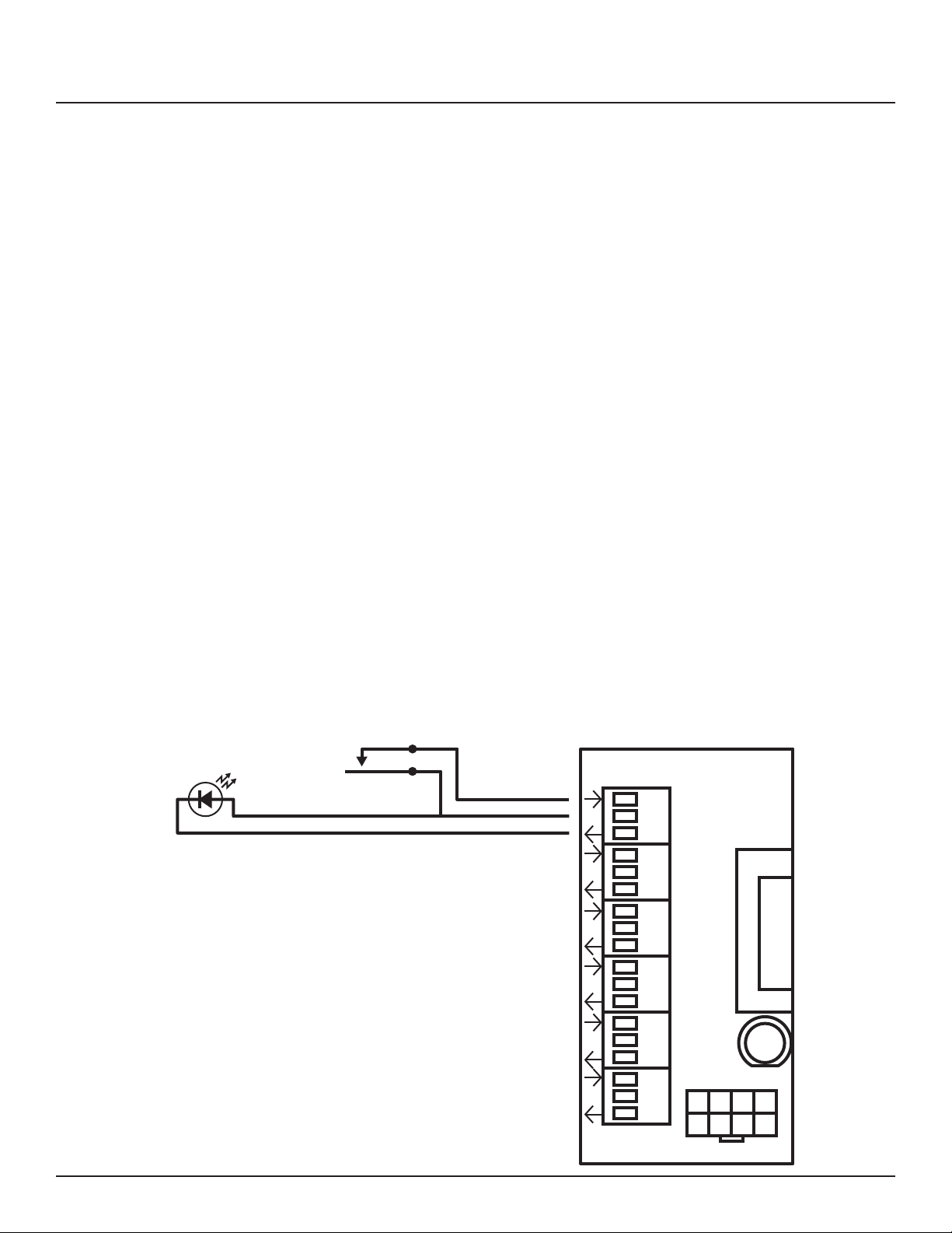
To connect your re alarm or emergency management system
to the RPC, follow these steps.
1. From the re alarm unit or latching Emergency Shuto
switch, wire the Normally Open (NO) contacts to the IN and
24V positions of Digital I/O Port #1 on the Controller.
2. If a remote status indicator is used, ensure that the positive
terminal is wired to the 24V position and the negative
terminal is wired to the OUT position of Digital I/O Port #1.
3. When the Normally Open contacts are closed, the status
indicator should immediately light and all breakers that
have been selected for E. Shuto should cycle to OFF.
4. When the contacts are released, the status indicator should
extinguish and all breakers that were ON when E. Shuto
was activated should return to the ON state.
See Chapter 5 to con gure the software for emergency
shutdown.
Figure 4-4: Emergency shutdown
wiring
24 VDC LED
Status Indicator
Normally Open
Fire Alarm Contacts
Digital I/O
1
2
3
4
5
IN
24V
OUT
OFF
16
6
Left Bus
139-0498-0116
Page 17
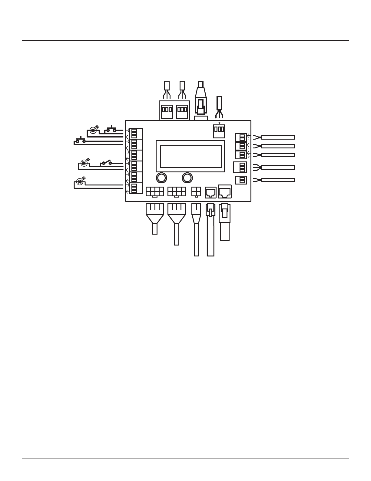
Figure 4-5: Control Wiring
24 VDC LED
Indicator
Momentary
OFF
24 VDC LED
Indicator
Maintained
Contact Switch
Light Sensor for
Zone Control
Momentary ON
Contact Switch
Digital I/O
IN
1
24V
OUT
2
3
4
5
6
cc
––++
Thru
Input
DMX-512 Control
ONOFF
Left Bus Right Bus
Ethernet Cable to
Facility Network
RX TX
Ethernet
Cat 5e
RS-232
I/O
Power
MPE
Analog
Inputs
1
2
3
Analog Inputs for
Control Functions
Audio Sensing Timer
+
c
–
+
–
24VDC source for
external device
Chapter Four--Wiring
TCP/IP
DMX
RS-232
Left Breaker
Control Bus
RJ-45 8P8C Flat Cable
to Controls Port on MPE
Right Breaker
Control Bus
RJ-25 6P6C Flat Cable
to I/O Port on I/O Card
24 VDC from P/S Unit
Transducer Input Lines
Install and connect a standard Cat. 5e cable from the facility
network to the Controller Ethernet port.
If DMX-512 is being used to control the panel, install and
connect a shielded pair cable from the DMX source to the
Controller DMX Input three-position spring-clamp header.
Terminate common, DMX– and DMX+ from left to right in the
header. Follow the same wiring guide for the DMX Thru header.
If RS-232 is being used to control the panel, install and connect
a shielded pair cable from the RS-232 source to the Controller
RS-232 three-position spring-clamp header. Terminate receive,
ground and transmit from left to right in the header.
139-0498-01.17 17
Page 18
Chapter Four--Wiring
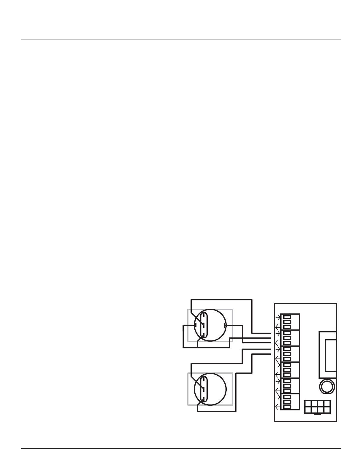
Switch Wiring Instructions The I/O ports on your RPC controller allow for a variety of
switch options.
LynTec SS-2 Switch Set
Using a standard LynTec SS-2 Switch Set with illuminated ON
switch. See Figure 4-6
1. Wire the ON switch to Digital I/O port 2 on the left edge of
the Controller board as follows:
i. Connect the 24VDC Common (center terminal of the I/O
port) to the C pin of the ON switch. Jumper the C pin of
the ON switch to the + pin.
ii. Connect the Input terminal (arrow pointing towards
header) to the NO pin of the ON switch.
iii. Connect the Output terminal (arrow pointing away from
header) to the – pin of the ON switch.
2. Wire the OFF switch to Digital I/O port 3 on the left edge of
the Controller board as follows:
i. Connect the 24VDC Common terminal to the C pin of
the OFF switch.
ii. Connect the Input terminal to the NO pin of the OFF
switch
Figure 4-6
Lyntec SS-2 Wiring Diagram
18
ON
OFF
Digital I/O
NC
+
NO
C
NC
NO
C
–
IN
1
24V
OUT
2
3
4
5
6
OFF
Left Bus
139-0498-0118
Page 19
Chapter Four--Wiring
SS-2PL and SS-2LRP Locking Switch
Sets
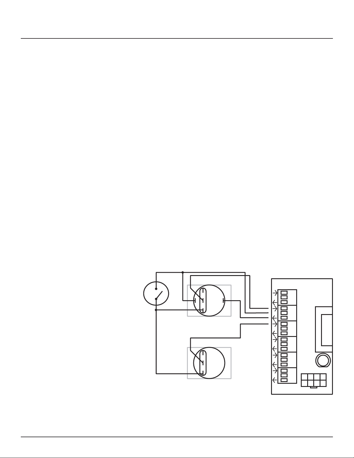
Using a standard LynTec SS-2PL or SS-2 LRP Switch Set with
illuminated ON switch. See Figure 4-7
1. Wire the ON switch to Digital I/O port 2 on the left edge of
the Controller board as follows:
i. Connect the 24VDC Common (center terminal of the I/O
port) to the + pin of the ON switch.
ii. Connect the + pin on the on switch to the 1 pin on the
lock.
iii. Connect the Input terminal (arrow pointing towards
header) to the NO pin of the ON switch.
iv. Connect the Output terminal (arrow pointing away from
header) to the – pin of the ON switch.
v. Connect the C pin on the ON switch to the 3 pin on the
lock.
2. Wire the OFF switch to Digital I/O port 3 on the left edge of
the Controller board as follows:
Figure 4-7
iii. Connect the 3 pin on the lock to the C pin on the OFF
switch.
iv. Connect the Input terminal to the NO pin of the OFF
switch
LOCK
1
3
ON
NC
+
NO
C
OFF
NC
NO
C
–
Digital I/O
1
2
3
4
5
6
IN
24V
OUT
ON
Left Bus
To con gure the Digital I/O port and link it to a zone see
Chapter 5.
139-0498-01.19 19
Page 20
Chapter Four--Wiring
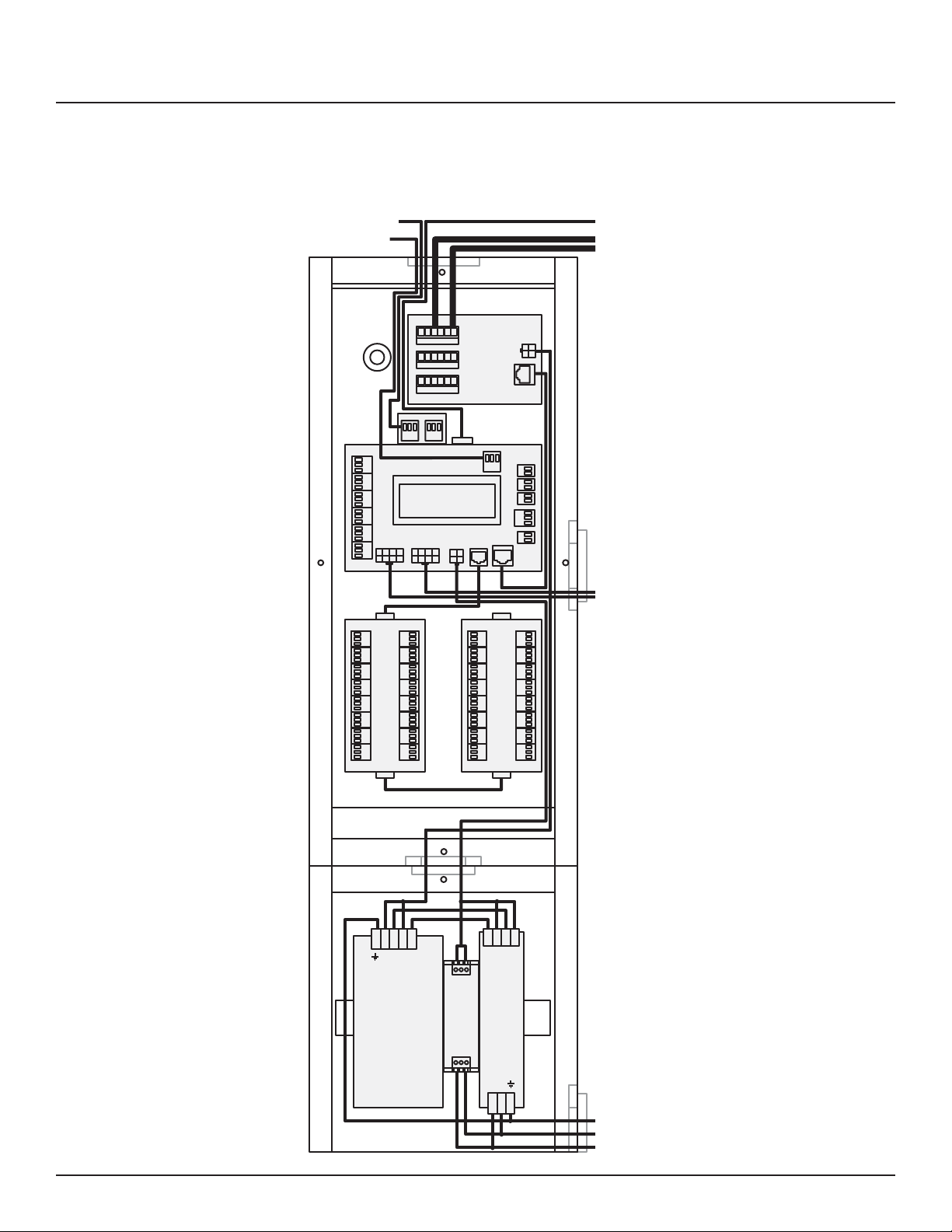
Figure 4-10: Complete RPC Wiring
DMX-512 Input
RS-232 Input
I/O
1
2
3
4
5
L Bus R Bus PWR
6
I/O I/O
1
2
3
4
EE
5
6
7
8
IN
OUT
DMX-512
9
10
11
12
13
14
15
16
RS-232
C
S2
S3
S4
Cat 5e
I/O
M
MPE
1
2
3
4
5
6
7
8
I/OI/O
PWR
Control
Analog
1
2
3
A
S
T
24V
9
10
11
12
13
14
15
16
LAN
Slave Panels
Control Bus
20
- -
B
+ +
12
OUT
T
IN
3
+ + – –
P
4
N L
Controller Power Breaker
139-0498-0120
Page 21
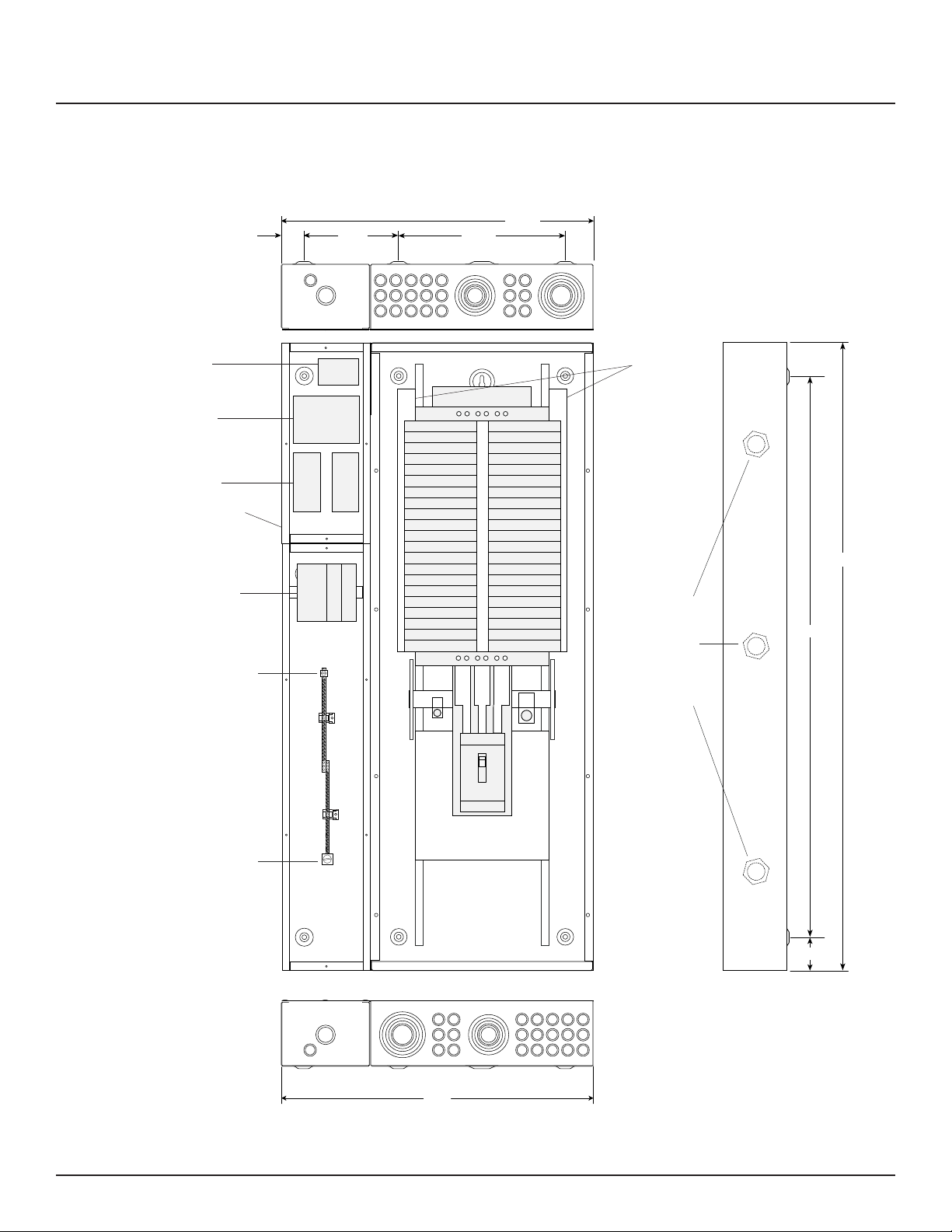
Figure 4-11: RPC Mechanical Drawing
Chapter Four--Wiring
Multi-Panel
Expander Board
Master Controller
Optional - Digital I/O
Expander Boards
Low Voltage Cabinet
Power Supply, Buffer
and VoltageTransducer
Feed
2/0 max.
2.00"
8.50"
15.00"
28.00"
High voltage interior may be
field inverted for top feed
Breaker
Control
Busses
1.5" I.D.
wiring
access
nipples
between
sidecars
and
panelboard
50.00"
56.00"
Isolated
Technical
Ground
Bar
46 positions
14 - 4 ga.
Feed
4/0 max.
Square D NF MB Panel
with LynTec sidecars.
Outside dimensions
28" w x 56" h x 6" d
139-0500-00 RPC 341 Mechanical 9/25/08
28.00"
3.00"
Standard RPC Main Breaker:
225 Amp - 65k AIR - MJG32225
Main Breaker options - Part # suffix
-MHG3110, MHG3125,
-MJG3150, -MJG3175, -MJG3200
(all 65k Amp Interrupt Rating)
Main Breaker wire:
3/0-350 kcmil Aluminum or Copper
200% Neutral has one feed lug that
accepts two 350 kcmil wires.
139-0498-01.21 21
Page 22

Chapter Four--Wiring
INITIAL POWER UP
PROCEDURE
With panel door open and breakers visible, turn on the panel
main breaker and the Controller Power 15 Amp circuit breaker.
The green ‘DC OK’ LED should illuminate on the Power Supply
and the green ‘STATUS’ LED on the Bu er unit should begin
ashing steadily. The Bu er ‘STATUS’ LED will be constantly lit
when the unit has been fully charged.
The Controller LCD display and orange Power LED should
illuminate. If installed, the orange Power LED’s on the I/O
Expander boards and the orange Power LED on the MPE board
will illuminate.
22
139-0498-0122
Page 23

Chapter 5--Control Setup (Web Page)
Chapter Five--Control Setup
OVERVIEW
STATUS
CONTROL
SETUP
There are 4 main tabs on your RPC web page. This page will give
you a quick overview of the pages and their functions.
The status page allows you to view the current status of the
breakers and zones. Zones and individual breakers cannot be
manipulated from this page.
This page allows the user to manipulate individual breakers
as well as breaker zones. “All ON/OFF” and “Hurry-O ”
commands can also be triggered from this page.
The setup section allows you to setup and use the RPC controller.
From this section you can manipulate the network settings,
assign breakers to zones, create sequences, activate emergency
management features, create schedules and assign contact
closures.
CONTACT
VOLTAGE
139-0498-01.23 23
This page provides contact information for LynTec.
This page provides a voltage monitoring graph.
Page 24
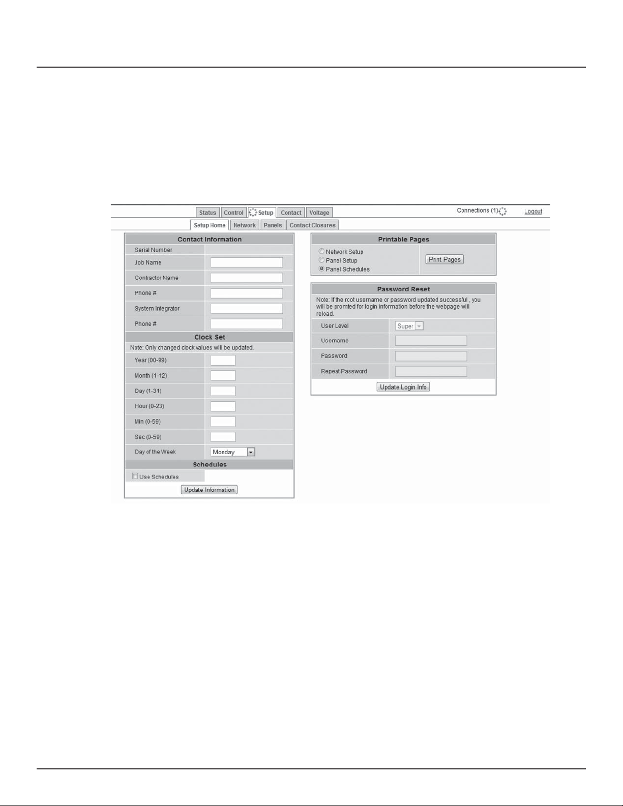
Chapter Five--Control Setup
Setup
SETUP HOME
This section will guide you through the process of setting up yur
RPC Controller. First enter the IP address or NetBios name into
your web browser. When the RPC screen pulls up. Select “Setup”
and “SetupHome” Tabs.
Figure 5-1--Setup Home
24
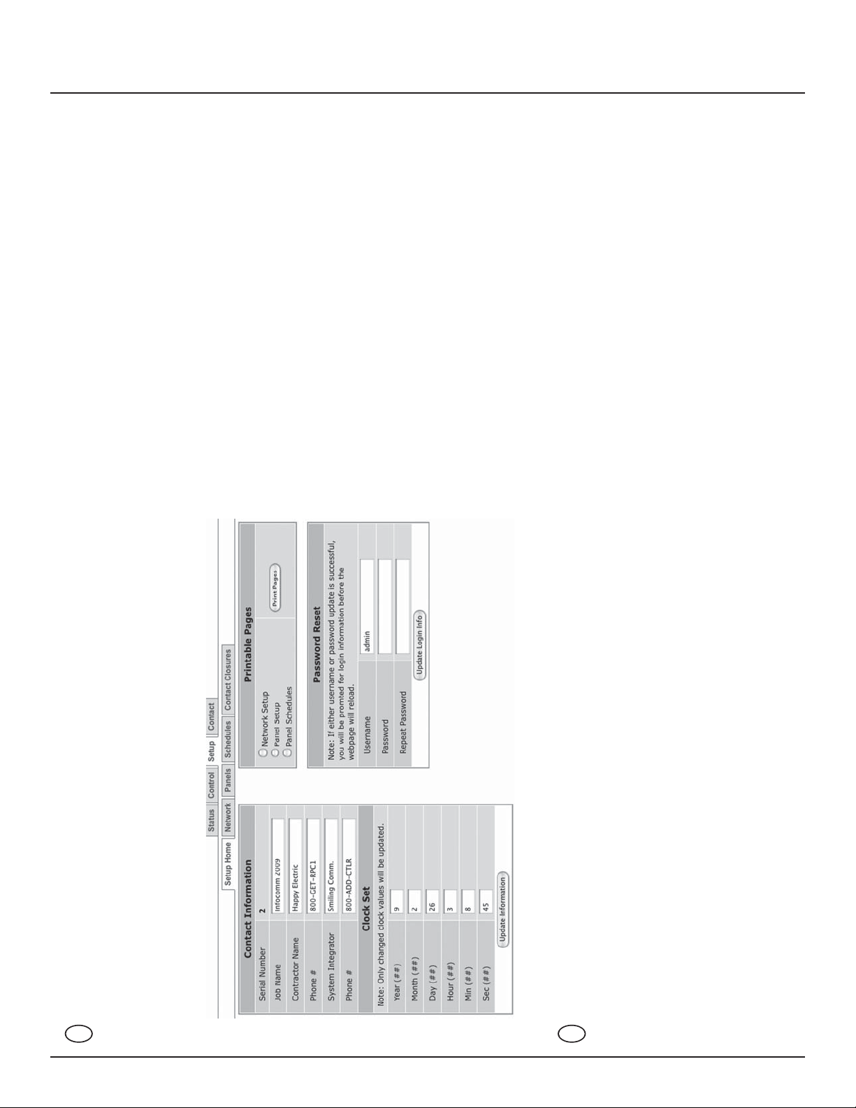
To set the username and password for your panel, click
the Setup tab. The Setup Home tab should be displayed.
The default username displayed should be “admin” and the
password elds should be “pw”. Enter the desired username
in the rst eld, password in the second and then retype the
password again in the third eld. When ready, click the Update
Login Info button to save the changes to Controller memory.
Contact information for service can also be entered on this
page. Under the Serial Number eld, enter the name and
phone number of the installing contractor (Electrician) and the
system integrator (A/V Technician) for future reference. Save
this information by clicking the Update Information button
below the Clock Set portion of the window.
139-0498-01.24
Page 25
Network setup
Chapter Five--Control Setup
Basic date and time information will be displayed in the Clock
Set elds. Verify that the year, month and day are correct. Set the
hour to the appropriate time for your time zone and verify that
the minute displayed is correct. Save this information by clicking
the Update Information button below the Clock Set portion of
the window.
Click the radio buttons for any pages to be printed out under the
Printable Pages header. To print the Network Setup, Panel Setup
or Panel Schedules pages at any time, ensure the desired buttons
have been selected and then click the Print Pages button to the
right. Please print a copy for your records after setup is complete.
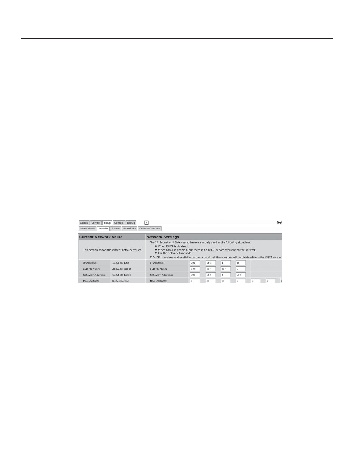
Figure 5-2--Network Settings
Figure 5-2 shows the network settings portion of the Network
setup.
The left hand side of the screen shows the current network
values. It is recommended that the user consult with the
network administrator before changing these values.
The IP, Subnet and Gateway addresses are only used in the
following situations:
• When DHCP is disabled
• When DHCP is enabled, but there is no DHCP server available
on the network
• For the network bootloader
If DHCP is enabled and available on the network, all these values
will be obtained from the DHCP server.
139-0498-01.25 25
Page 26
Chapter Five--Control Setup
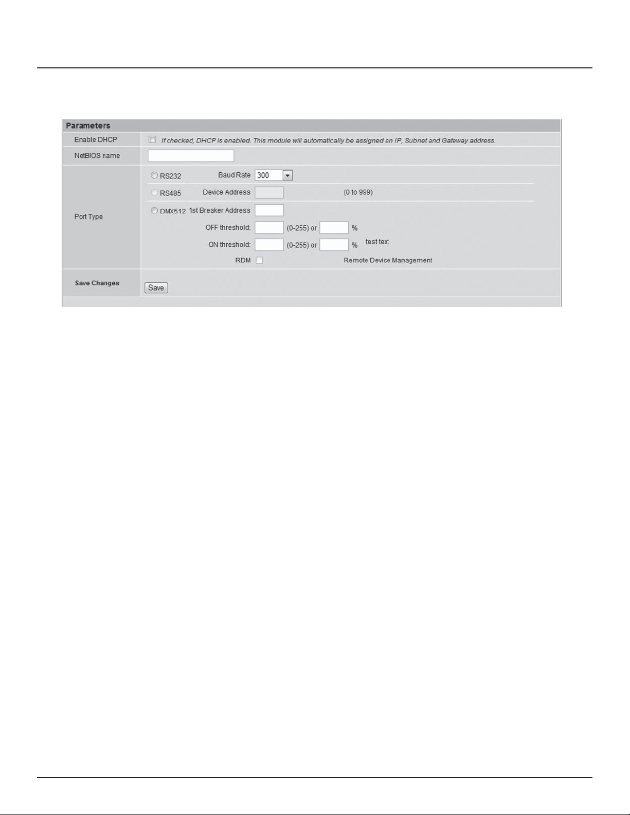
Figure 5-3: Interface options
NetBios Name
The NetBios name defaults to LynTecRPC. Each
master panel in your system should be assigned a
unique NetBios name. After names are assigned the
user can access the system web page by entering the
NetBios name into the web browser instead of using
the IP address.
Port Type The port type section is used to select the preferred serial
communication protocol. The controller defaults to Ethernet
(TCP/IP) for setup but can be controlled in conjunction with
RS-232, RS-485 or DMX-512 protocols.
For RS-485 operation the device address must be entered in
the adjacent eld.
For DMX operation use the following steps:
Enter the rst individual breaker address. All motorized
breakers will be automatically assigned to consecutive
addresses. Zone control is not availible with DMX operation.
26
Please note that selecting DMX control will disable web
control.
139-0498-01.26
Page 27
Chapter Five--Control Setup
Panel Setup
BREAKER SETUP
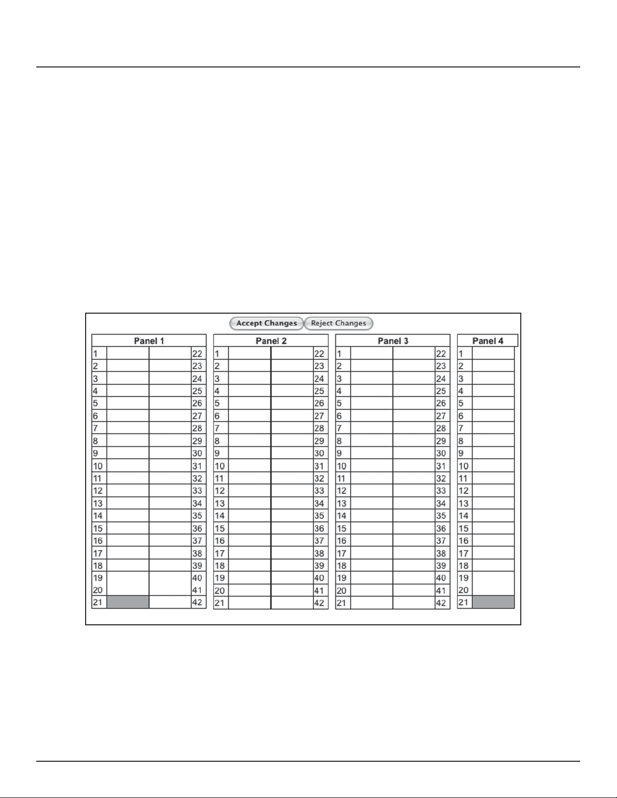
This section explains how to setup your panel and
motorized breakers for remote operation.
To setup breakers, follow these steps:
1. Under Setup, go to the Panels tab.
2. After breakers are installed by a quali ed electrician,
click the “Scan Breakers” button. Motorized breakers are
represented in white, unmotorized breakers or blank spaces
are represented in gray.
Figure 5-4
3. If panel con gurations are correct, click “Accept Changes”
139-0498-01.27 27
Page 28
Chapter Five--Control Setup
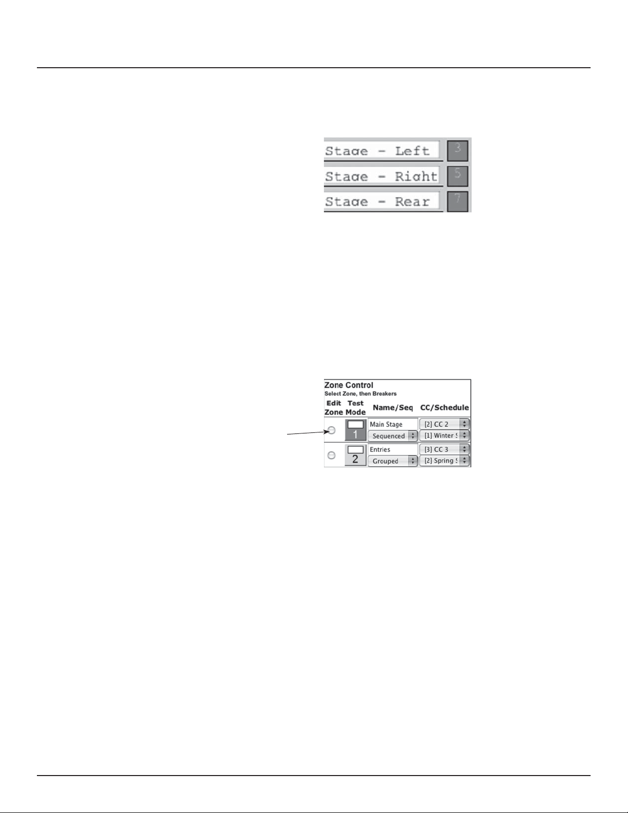
4. Assign names to the breakers. (Figure 5-5)
Figure 5-5
ZONE SETUP
Breakers can be controlled individually or arranged into zones.
Breakers in zones can be toggled at 25 ms intervals (Grouped
Operation) or at variable intervals (Sequenced Operation).
To setup a Zone follow these steps:
1. Choose which zone you would like to edit. (Figure 5-6)
Figure 5-6
Select to
Edit
28
139-0498-01.28
Page 29
Chapter Five--Control Setup
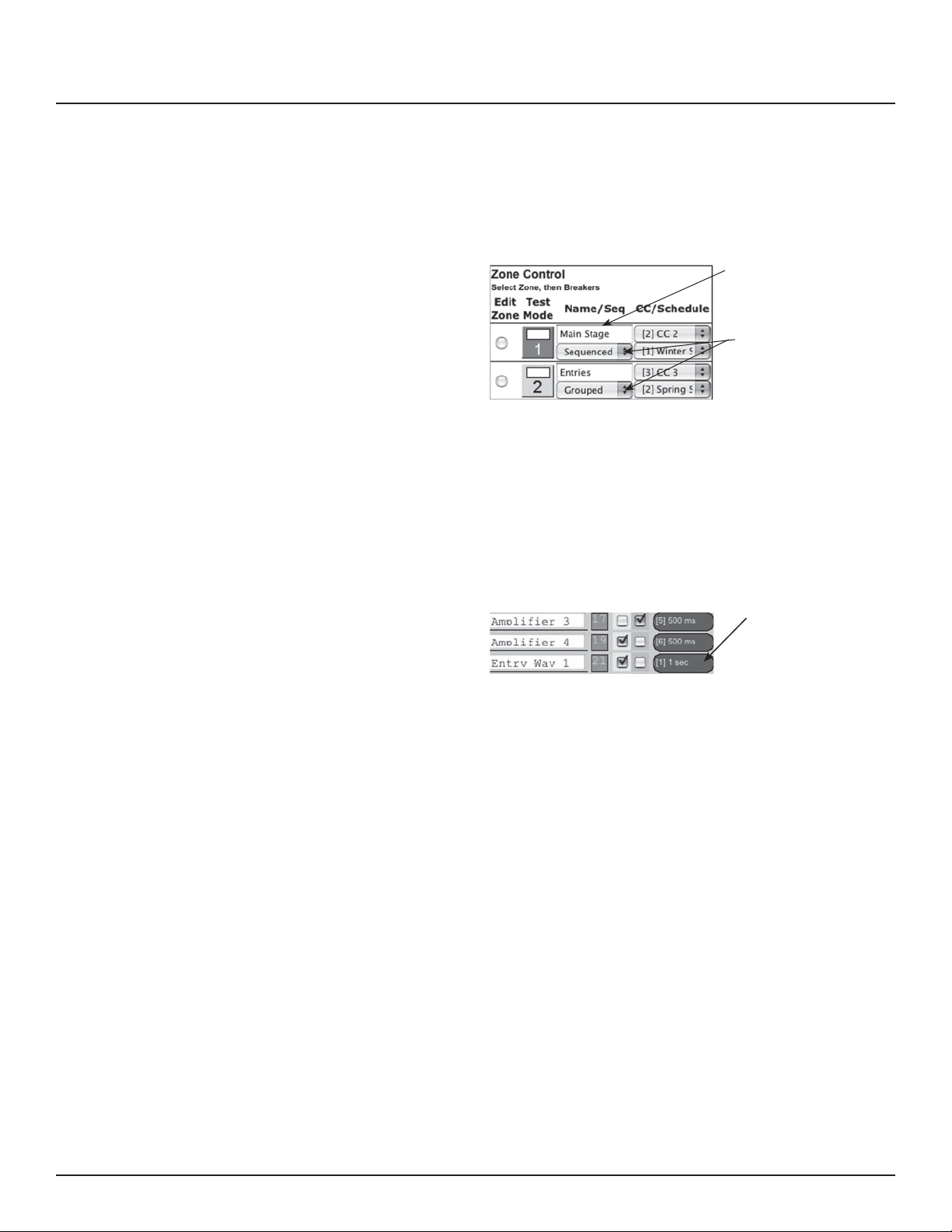
2. Name the Zone. (Figure 5-7)
3. Choose Grouped or Sequenced operation. (Figure 5-7)
Figure 5-7
Name the Zone
Choose grouped or
sequenced from the
dropdown
5. Select a breaker to add to the zone by clicking on the
breaker you want to add. Only motorized breakers
(indicated in green) may be added to zones. (Figure 5-8)
Scroll down to add breakers from additional panels.
Figure 5-8
Click on the green oval
to add a breaker to a
zone.
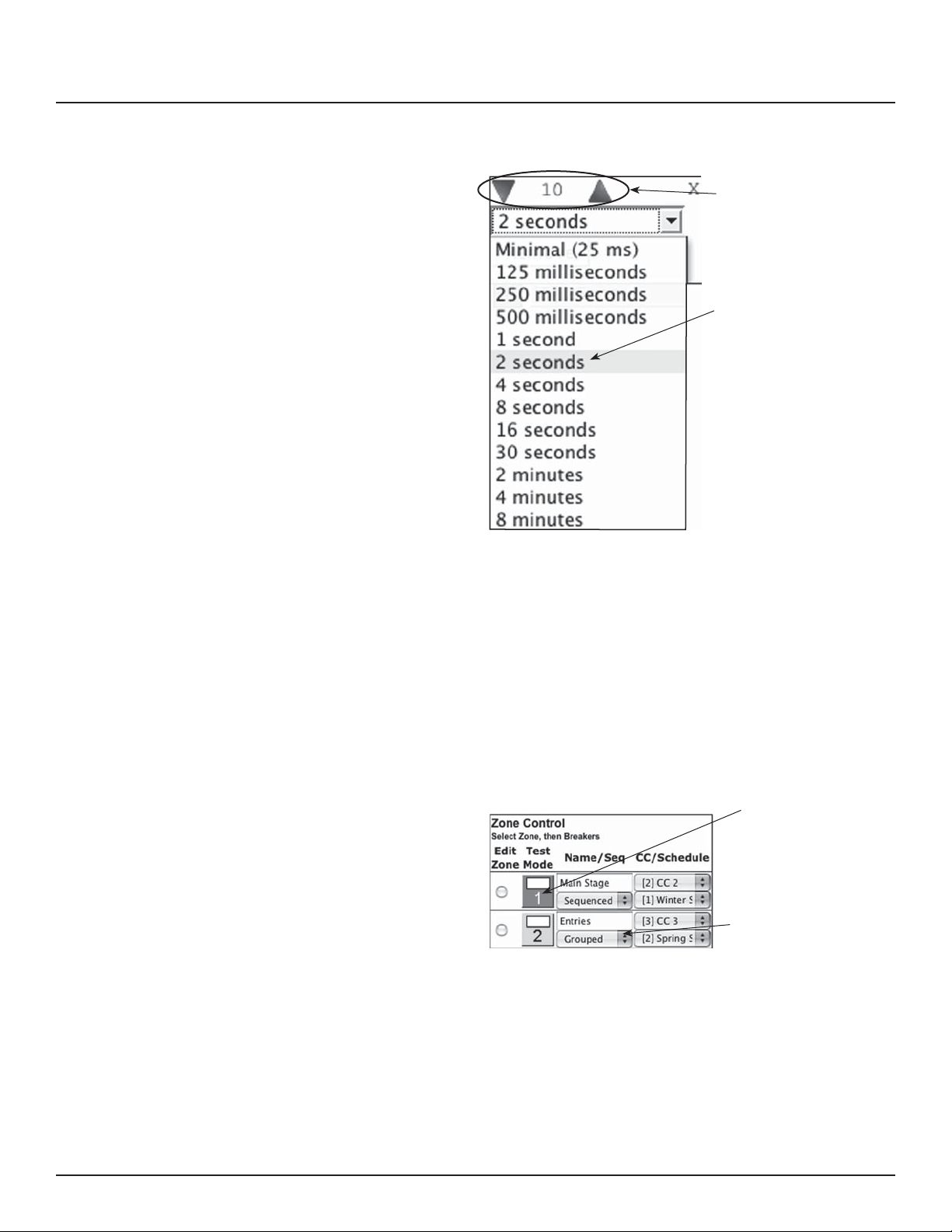
6. Select the position of the breaker in the zone. This set
the order in which they turn on and o . (Figure 5-9)
7. For sequenced operation, select a delay time from the
dropdown. Breakers in grouped zones toggle in 25ms
intervals. (Figure 5-9) Delay time is the amount of time
after a breaker changes state, before the new breaker
in sequence changes state.
139-0498-01.29 29
Page 30
Chapter Five--Control Setup
Figure 5-9
Click the up/down
arrows to change the
breaker’s position in the
zone.
Select a delay time for the
breaker.
8. Click the “Close” button when nished to save. OR, click
“Remove” to remove the breaker from the zone.
9. When nished adding breakers to the zone, click the “Test
Mode” (Figure 5-10) button to do a blind test (breakers will
not actually toggle). Please note that delay times larger
than one second are reduced to one second in Test Mode
for expediency.
Figure 5-10
Click to test zone
operation.
Change drop down to
“Disabled” to disable
zones.
10. Disable zones that are not in use so they do not appear in
the status and control pages (Figure 5-10).
30
11. Click “Save Changes” (Figure 5-11) to save zone information
when nished.
139-0498-01.30
Page 31
Figure 5-11
Chapter Five--Control Setup
GLOBAL PREFERENCES
SETUP
Labeling In addition to labeling breakers, each panel in your RPC system
Numbering and addressing
This section guides you through the setup process for the
many features and preferences in your RPC system.
can be named (up to 16 characters) and the changes dated
(Figure 5-12). For multi-panel systems, scroll down to see
additional panels.
Figure 5-12
The RPC system allows the user to choose top/bottom panel
numbering or left/right panel numbering. (Figure 5-13) It also
allows you to select the direction for addressing.
Figure 5-13
139-0498-01.31 31
Page 32
Chapter Five--Control Setup
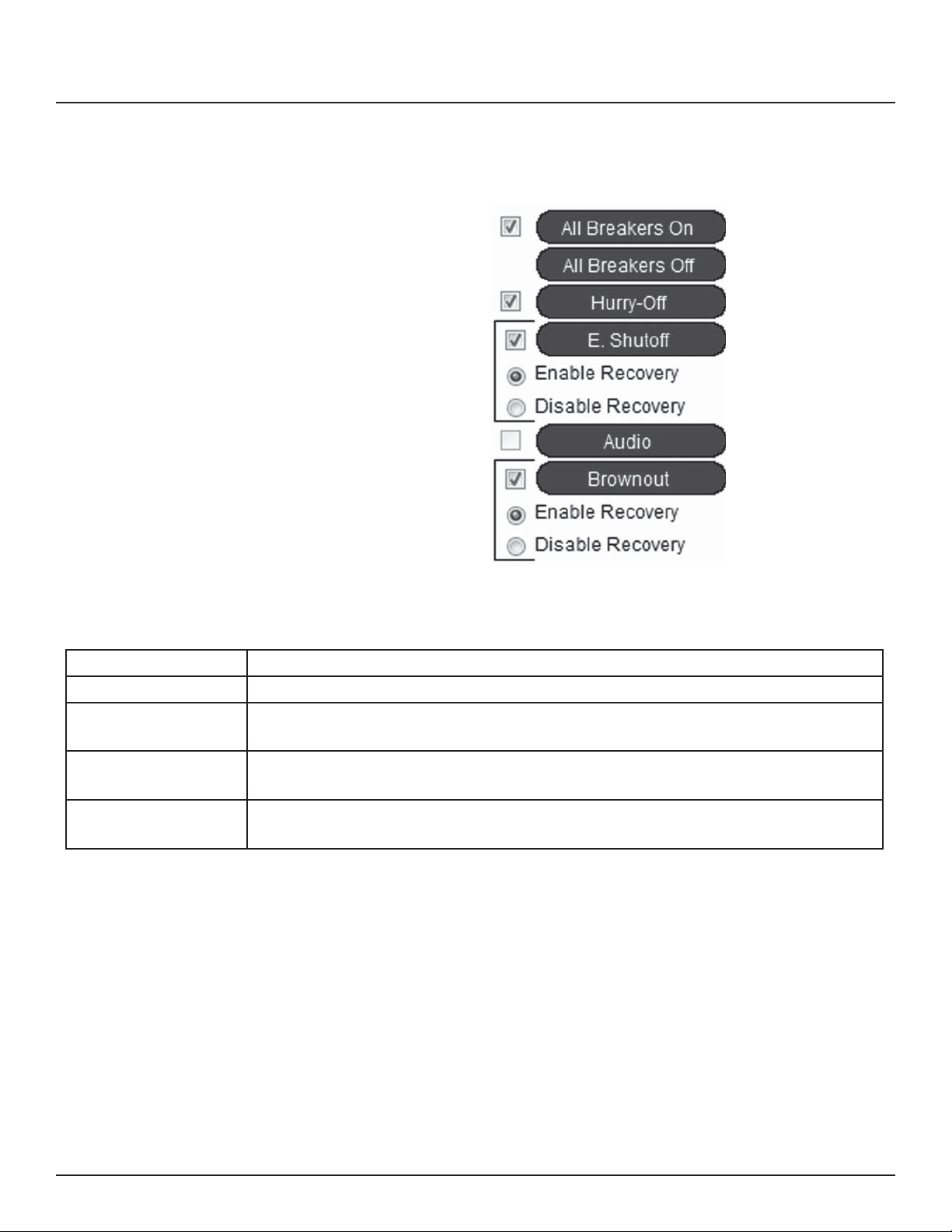
Global Control Preferences The following features can be selected for additional system
exibility
Figure 5-13
Table 5-1
All On/O Turns all the breakers on or o by order of zone and sequence.
Hurry-O Manually turns breakers o .
Emergency Shuto Turns Selected breakers o when the re alarm or emergency management
system engages. Must be connected to I/O position one.
Audio Activates the optional audio sensing timer. The timer monitors audio lines and
shuts the system down if there is no activity after a pre-determined interval.
Brownout Turns selected breakers o in the event of a brownout. Turns circuits back on
when voltage stabilizes.
32
139-0498-01.32
Page 33
Selecting breakers for Brownout or
Emergency Shutdown
Figure 5-14
Chapter Five--Control Setup
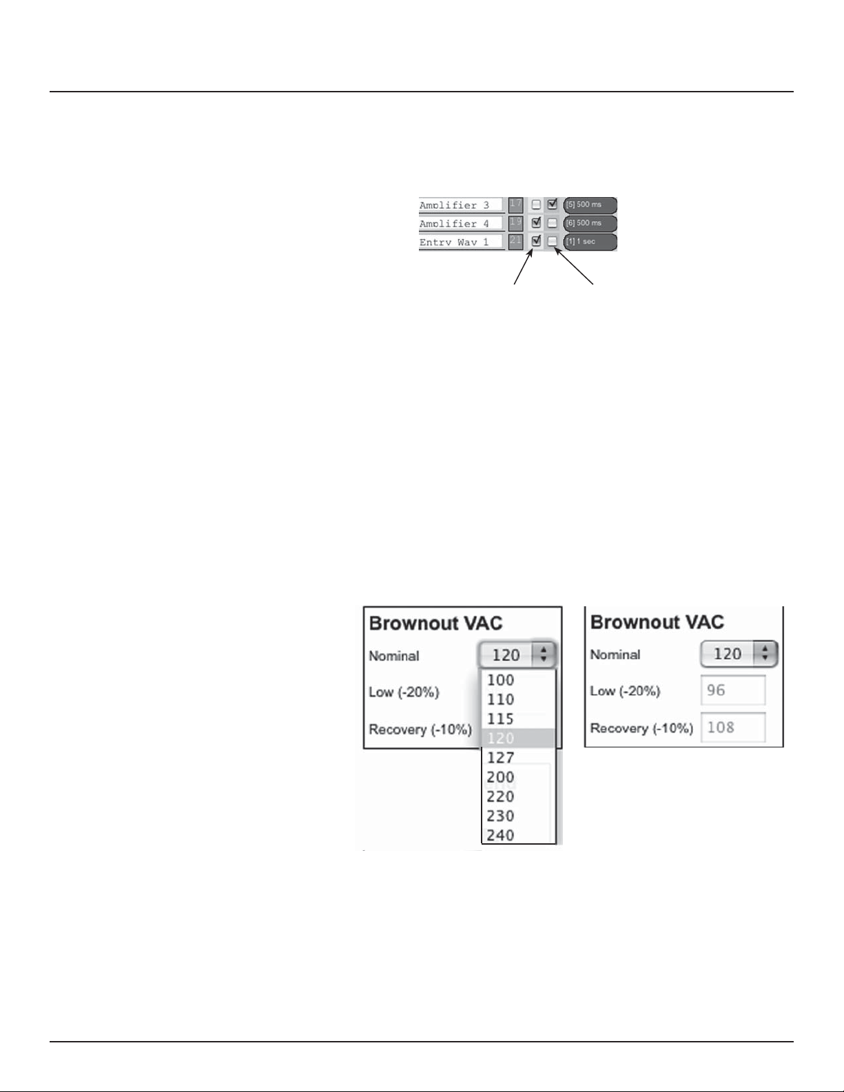
Select breakers to actuate in
the event of a brownout in
green outlined check boxes.
Select breakers for
emergency shutdown in
pink outlined check boxes.
Select breakers to actuate in the event of a brownout by
checking the green box next to the breaker. Select breakers to
turn o in the event of a re or other emergency by checking
the pink box next to the breaker. The status of unchecked
breakers will remain una ected.
Brownout Thresholds
Figure 5-15 Before: After:
If the brownout feature has been selected, the nominal AC
Voltage should be set for proper operation. Click the pull
down menu in the brownout VAC box and select the nominal
operation voltage for the panel (100-240 VAC) The brownout
thresholds will automatically adjust for shuto at nominal -20%
and recovery at nominal -10%..
139-0498-01.33 33
Page 34
Chapter Five--Control Setup
Schedule Setup
Figure 5-16
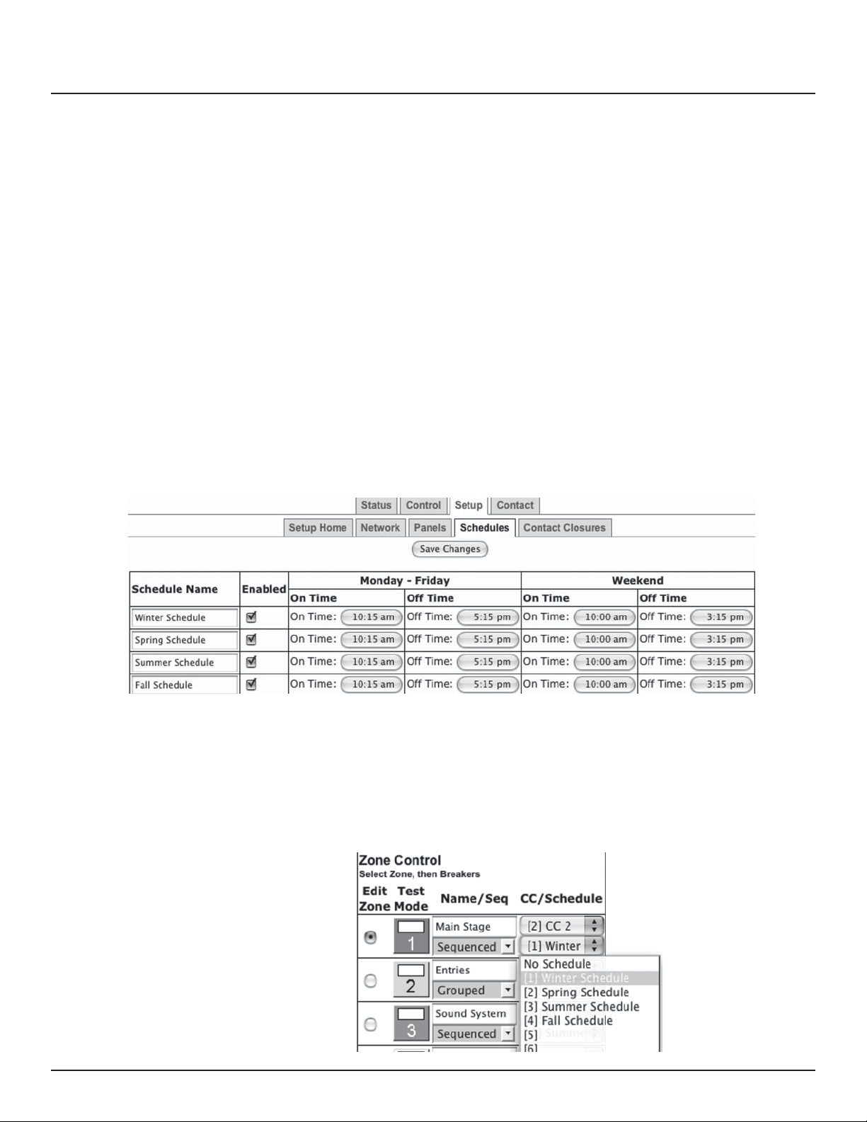
Follow these steps to set a schedule.
1. Rename each schedule as desired
2. Assign weekday (M-F) on and o times by clicking on time
and o time buttons, using pull-down menu and clicking the
pick button to select.
3. Assign weekend (S-S) on and o times by clicking on time
and o time buttons, using pull-down menu and clicking the
pick button to select.
4. Enable each schedule by clicking the checkbox for that line.
5. Click the Save Changes button at the top of the page to save
updated schedules.
Assigning Schedules to Zones To assign a schedule to a zone in the “Panel” screen:
1. Select the desired zone from the drop down box.
2. Save changes.
Figure 5-17
34
139-0498-01.34
Page 35
Chapter Five--Control Setup
Contact Closure Setup
Figure 5-18
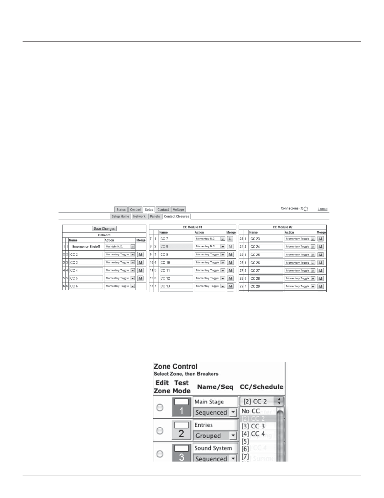
Con gure the digital I/O port and link it to a zone as follows:
Note: If the Emergency Shuto feature is selected, the rst
position in the Onboard eld (on the Controller) is automatically
assigned to that.
1. Rename each contact closure as desired
2. Select contact closure action type
3. Use CC Module 1 and CC Module 2 only if I/O Expander
boards are installed.
4. Save Changes
Assigning Contact Closures to Zones To assign a contact closure to a zone in the “Panel” screen:
1. Select the desired zone from the drop down box.
2. Save changes.
Figure 5-19
139-0498-01.35 35
Page 36

Chapter Five--Control Setup
Individual Momentary Contact ON and
OFF Pushbuttons
Using a standard LynTec SS-2 Switch Set with illuminated ON
switch or two illuminated pushbuttons:
Con gure the Digital I/O port and link it to a zone as follows:
1. Follow the previous instructions for naming the contact
closure and setting closure type.
2. Click the M button at the right side of the rst of the two
ports used. The name box and M button in the second port
should turn gray and the Action selections should default to
Momentary NO. (normally open)
3. Ensure that both of the Action selections for both ports are
set to Momentary NO.
4. Enter a name in the text eld of the CC used that is
indicative of the zone it will control.
5. Click the “Save Changes” button at the top of the Onboard
I/O box.
6. Follow the previous instructions for assigning a contact
closure to a zone, selecting the merged ports.
7. Click the Save Changes button in the upper left corner of
the Panels page.
Verify proper operation of your Switch Set:
1. Press the ON switch. Breakers in the selected zone should
immediately begin actuating.
2. The ON indicator should ash steadily until all of the
breakers are in the on state.
3. When the zone has completed, the ON indicator should
remain constantly lit.
4. Press the OFF switch. Breakers in the selected zone should
immediately begin actuating.
5. The ON indicator should ash steadily until all of the
breakers are in the o state.
6. When the zone has completed, the ON indicator should
remain constantly dark. Note: When using two illuminate
pushbuttons the OFF indicator will remain constantly
lit when the zone has completed. (OFF indicator will
extinguish immediately when ON is pressed again.)
36
139-0498-01.36
Page 37
Chapter Six: Operating your RPC
Figure 6-1
Chapter Six--Operation
Using the built-in web page
Using a secondary controller For DMX, follow the manufacturer’s instructions using the DMX
139-0498-01.37 37
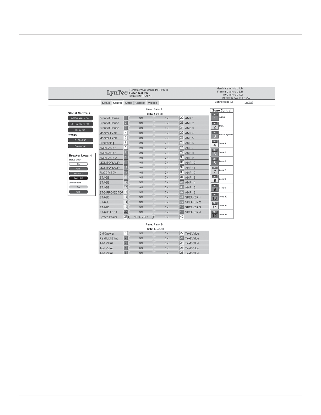
To operate the RPC using the built in web page, select the
control tab from the top of the page. Once on the CONTROL
page, simply click each breaker for individual control. Or,
click a zone for zone control. “All zones ON” and “Hurry-O ”
commands can also be executed from this page.
addresses entered in the NETWORK page ( see pang 26).
RS-232 and TCP/IP schemes are in Appendix B (page 38).
Page 38
Appendix A
Appendix A--RPC Quick
Start Guides
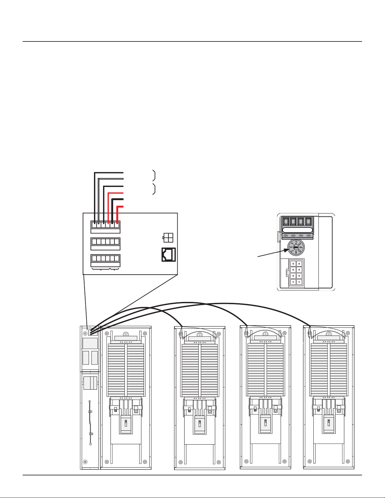
RPC to RPS Wiring Instructions
Figure A-1
Left Bus B
Left Bus A
Right Bus B
Right Bus A
Slave Common
Slave +24VDC
Slave Panel 2
Slave Panel 3
Slave Panel 4
Communication Power
Master Panel
Twisted Pair
Twisted Pair
Powe r
Controls
Slave Panel 2
B A +
Slave
address
selector
Slave Panel 3 Slave Panel 4
38
139-0498-01.38
Page 39

Appendix A
1. If RPS Slave panels are being used in conjunction with an
RPC Master panel, install and connect one 18 AWG six (6)
conductor (Belden 27600 A or equivalent) or two 18-24 AWG
twisted pairs for data and one 16-18 AWG for power per RPS
unit. Terminate the Left Bus B, Left Bus A, Right Bus B, Right
Bus A, Common (–) and 24VDC (+) in the screw-terminal
header for that RPS (Slave Panel 2 – 4) from left to right.
2. At the RPS Slave panels, strip the cable sheath back
approximately 20 inches. Cut the conductors for Left Bus
B, Left Bus A, – and + down to approximately 4 inches and
terminate them in the Left Bus screw-terminal header from
left to right. Terminate the remaining two conductors in
the Right Bus B and Right Bus A positions of the Right Bus
screw-terminal header.
3. Using two cut lengths of 18 AWG wire, install jumpers from
Left Bus – and + to Right Bus – and +. Right Bus will not
operate without these jumpers installed to provide 24VDC
power and common.
Table A-1
4. Set the slave address selectors as follows:
Left Control Bus Right Control Bus
Panel #2 2 3
Panel #3 4 5
Panel #4 6 7
139-0498-01.39 39
Page 40
Appendix A
RPC Quickstart Guide
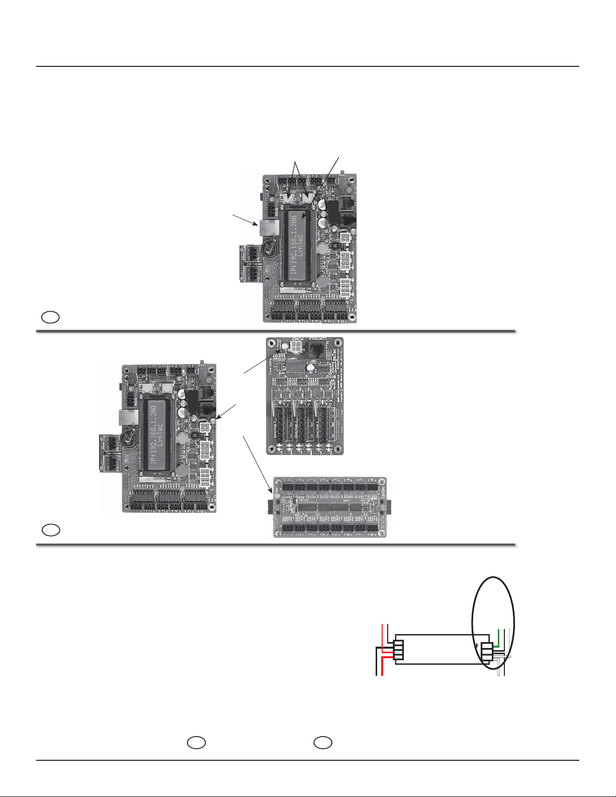
Connect a computer to the control
board using a CAT5 crossover
cable OR connect the RPC to your
network.
4
If connecting via a crossover cable:
With a computer directly connected
to the RPC through the Ethernet
port, change the computer’s IP
address manually so it is in the same
default IP subnet that the RPC uses:
192.168.1. The default IP address of
the RPC is 192.168.1.250.
Ethernet Port
POWER LEDS
Yellow
Buttons
LCD
Screen
If connecting via a network:
Connect the RPC to the network via
the Ethernet port. Push the upper
yellow button twice or until the IP
address appears on the LCD screen.
Once the 15A breaker is connected
and switched on, confi rm that the
orange power LEDs on each circuit
board are lit.
3
LynTec
RPC
Quick Start Guide
Control Board
Make sure that the panel(s) have
been wired by a qualifi ed electrician
and that there is power to the
panel(s).
Confi rm that RPS (slave) panels
are connected to the master as
indicated in the “RPC to RPS Wiring
Instructions” bulletin.
1
Multi-Panel Expander
Board
If LEDs do not light, check chapter
I/O Expander
Board
Controller Cable
Controller Cable
+ + – –
Power Supply DC –
Confi rm that the electrician has
connected the 15A breaker in the
master panel (position 21) to the
Power Supply DC +
power supply in the lower sidecar.
2
4 of the RPC manual to see that
circuit boards are connected
properly.
139-0522-00 RPC Quicksheet
15A Breaker
Panel Neutral Bus
Panel Ground Bar
N L
Transducer Load
Transducer Neutral
40
139-0498-01.40
Page 41
Appendix A
Open a web browser and access the status page via the IP address of the RPC.
(ex. http://192.168.1.250)
The default username is “admin” and the initial password is
“pw”.
If desired, set your username and password on the “Setup Home” page under
the “Setup” tab.
5
139-0498-01.41 41
Complete the RPC setup by following the steps in Chapter 5.
6
Page 42
Appendix A
RPC Contact Closure Wiring Instructions
Left Bus
OFF
IN
OUT
24V
Digital I/O
1
2
3
4
5
6
–
NO
C
NC
+
ON
NC
OFF
NO
C
the contact closure page.
(SETUP==> CONTACT CLOSURES)
On the RPC web page, go to
Note: If using emergency override
features, fi re alarm contact closures
must be wired into port 1.
5
(center terminal of the I/O port)
to the C pin of the ON switch.
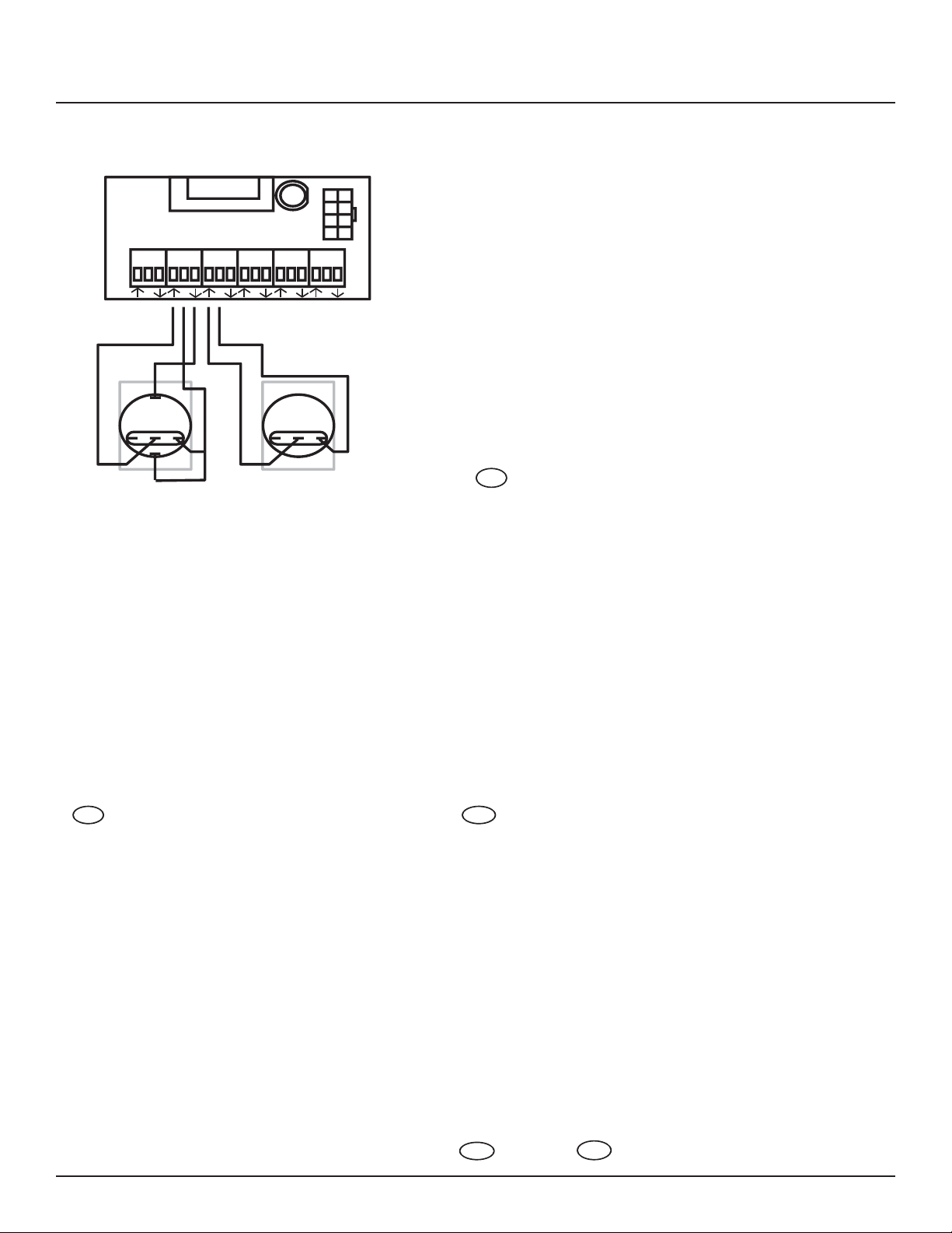
Wire the ON switch to a digital
I/O port on the left edge of the
Controller board as follows:
A. Connect the 24VDC Common
3
LynTec
42
(arrow pointing towards header)
B. Connect the Input terminal
RPC
Contact
to the NO pin of the ON switch.
(arrow pointing away from
header) to the – pin of the ON
switch.
C. Connect the Output terminal
Closure Wiring
Instructions
Using a standard LynTec SS-2 Switch
C pin and the + pin of the ON
switch.
D. Connect a jumper between the
Set with illuminated ON switch. (For
other types of switches, consult CH 4
of the instruction bulletin for wiring
Wire the OFF switch to a digital
I/O port on the left edge of the
4
Confi rm that RPS (slave) panels are
1
diagrams.)
terminal to the C pin of the OFF
switch.
Controller board as follows:
A. Connect the 24VDC Common
properly connected to the master as
indicated in the “RPC to RPS Wiring
Instructions” bulletin.
NO pin of the OFF switch
B. Connect the Input terminal to the
Complete all the steps in the “RPC
Quick Start Guide”.
2
139-0498-01.42
Page 43
Verify proper operation of your
Switch Set:
A. Press the ON switch. Breakers in
8
the selected zone should immedi-
ately begin actuating.
steadily until all of the breakers
are in the on state.
B. The ON indicator should fl ash
the ON indicator should remain
C. When the zone has completed,
constantly lit.
the selected zone should immedi-
ately begin actuating.
D. Press the OFF switch. Breakers in
steadily until all of the breakers
are in the off state.
E. The ON indicator should fl ash
the ON indicator should remain
F. When the zone has completed,
constantly dark. Note: When
using two illuminate pushbut-
tons the OFF indicator will remain
constantly lit when the zone has
completed. (OFF indicator will
extinguish immediately when ON
is pressed again.)
Appendix A
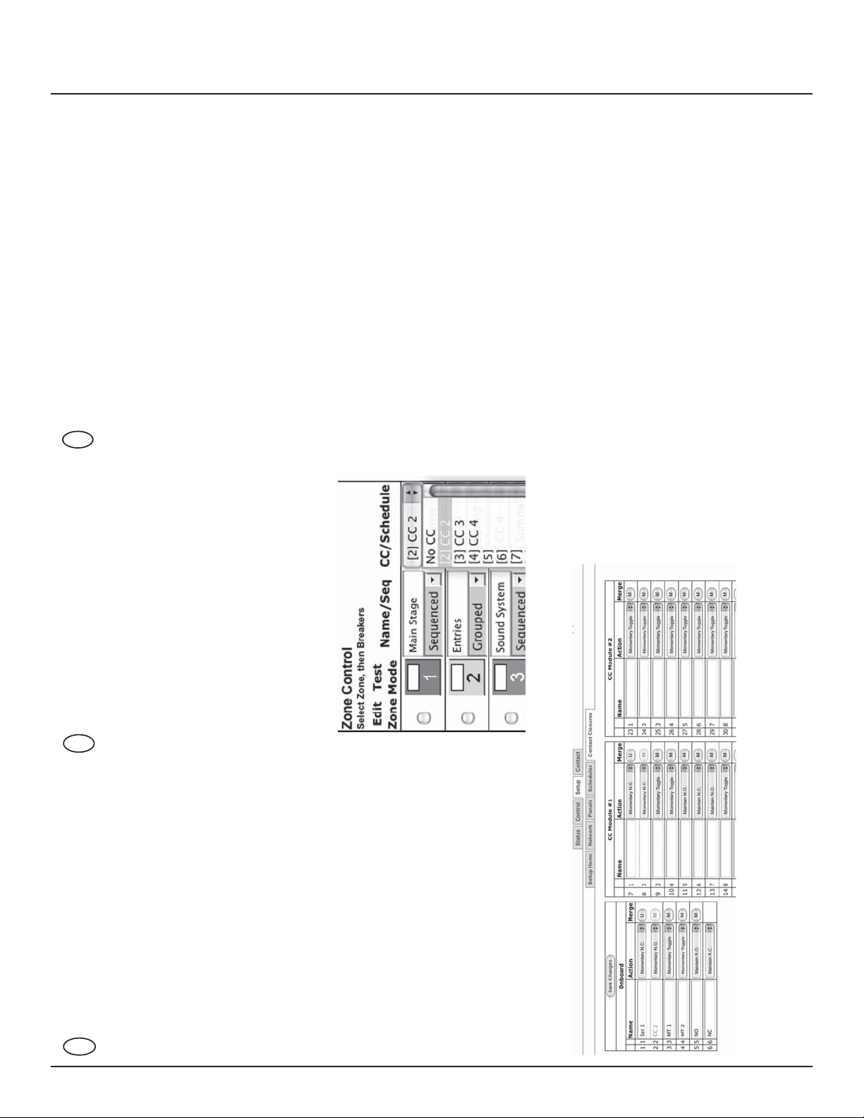
“CC/Schedule”, choose which
contact closure to assign to any
Assign the contact closure to a zone
in the “Panel” (SETUP==>PANELS)
screen:
A. In the ZONE CONTROL box under
zone using the drop down box.
Sequenced or Grouped operation
under “Name/Seq”.
B. Enable the zone by selecting
C. Save changes.
7
desired
Confi gure the digital I/O port.
Note: If the Emergency Shutoff
feature is selected, the fi rst
position in the Onboard fi eld (on
the Controller) is automatically
assigned to that.
A. Rename each contact closure as
the right side of the fi rst of the
two ports used. The name box
and M button in the second port
should turn gray and the Action
selections should default to
Momentary NO. (normally open)
B. Click the M (merge) button at
selections for both ports are set
to Momentary NO.
C. Ensure that both of the Action
D. Click the “Save Changes” button
at the top of the Onboard I/O
box.
6
139-0498-01.43 43
Page 44
Appendix B
Appendix B--RS-232 and TCP/IP
Protocols
RS232 PROTOCOL
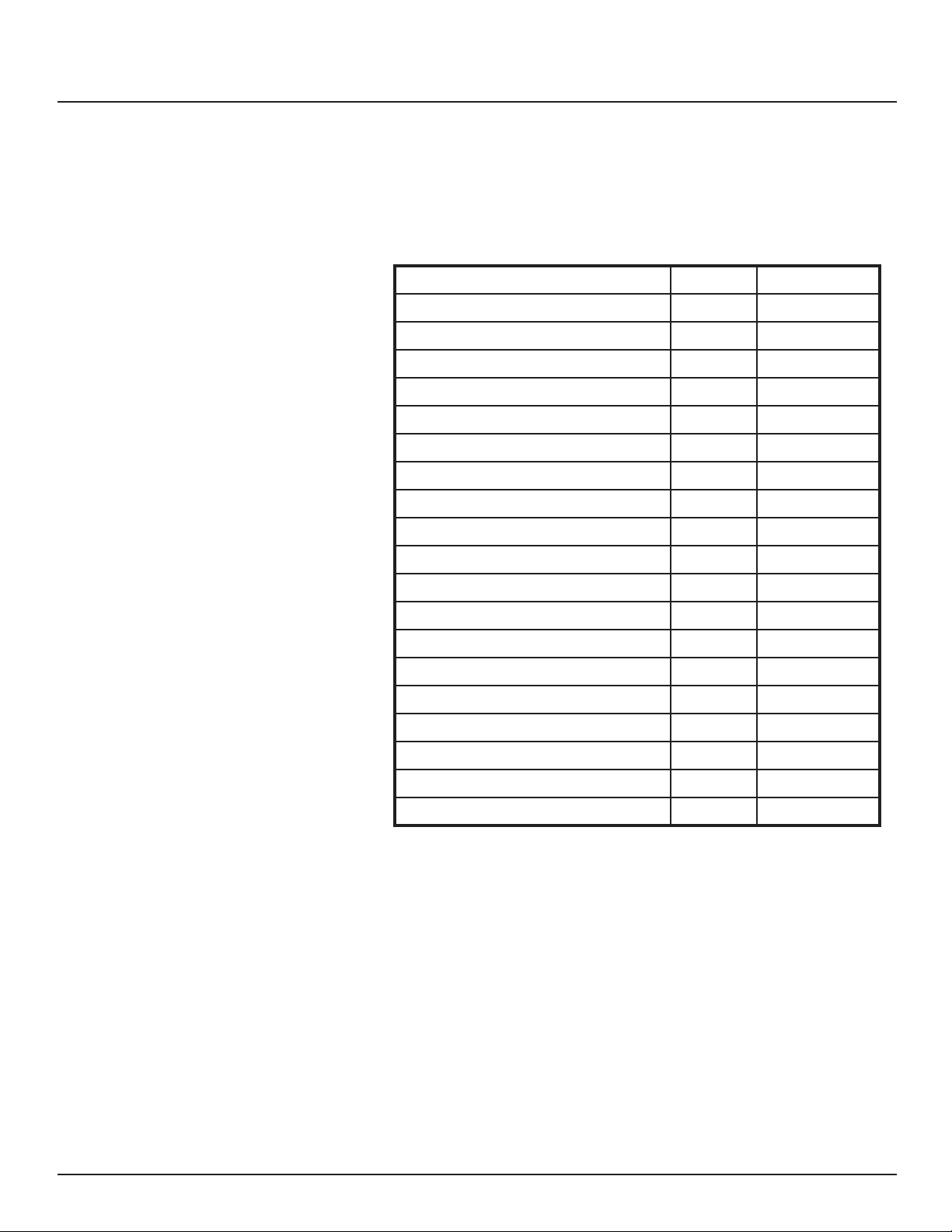
Table B-1 Command Codes
Command Decimal Hexidecimal
Start Byte 176 0xB0
Activate breakers 180 0xB4
Deactivate breakers 181 0xB5
Request all breakers status 183 0xB6
Activate zones 183 0xB7
Deactivate zones 184 0xB8
Request zones status 185 0xB9
Event ON 186 0xBA
Event OFF 187 0xBB
Event status 188 0xBC
Request breakers status 189 0xBD
Request bus status 190 0xBE
Breaker status identi er 200 0xC8
Zone status identi er 201 0xC9
Event status identi er 202 0xCA
Addressing Scheme
Breaker Related Commands
Emergency override identi er 203 0xCB
Checksum identi er 204 0xCC
Checksum digits 205-214 0xCD - 0xD6
Stop byte 240 0xF0
Breaker address:
1 byte. Numbers 1 through 168 (0x01 – 0xA8) are assigned to
populated breakers in sequential order
Zone number: 1 byte (1-12)
Activate breakers
0xB0, 0XB4, breaker_address_1, …, breaker_address_m, 0xF0
breaker_address_1, …, breaker_address_m – addresses of
breakers to be activated m<=168
44
139-0498-01.44
Page 45

Appendix B
Deactivate breakers
0xB0, 0xB5, breaker_address_1, …, breaker_address_n, 0xF0
breaker_address_1, …, breaker_address_n – addresses of reakers
to be deactivated n<=168
Activate/deactivate breakers
0xB0, 0XB5, breaker_address_1, …, breaker_address_m, 0xB6,
breaker_address_1, …, breaker_address_n, 0xF0
breaker_address_1, …, breaker_address_m – addresses of
breakers to be activated breaker_address_1, …, breaker_
address_n – addresses of breakers to be deactivated m+n<=168
Request all breakers status
0xB0, 0xB6, 0xF0
Request breakers status
0xB0, 0xBD, breaker _address_i, breaker _address_j, …, breaker
_address_n, 0xF0
breaker_address_1, …, breaker_address_n – addresses of
breakers, status of which is requested
Request bus status
0xB0, 0xBE, bus, 0xF0
bus=0-7 – number of bus, status of which is requested
Reply to activate/deactivate breakers command: status of
updated breakers
0xB0, 0xC8, breaker_address_i, breaker_status_i, breaker_address_j,
breaker_status_j, …, breaker_address_n, breaker_status_n, 0xF0
breaker_address_i, breaker_status_i, breaker_address_j,
breaker_status_j, …, breaker_address_n, breaker_status_n
Addresses and status of breakers updated by the command reply
is generated for
139-0498-01.45 45
Page 46
Appendix B
Reply to request breakers status command:
Same format as “Request Bus Status”; contains addresses and
status of the breakers speci ed in the request command
Reply to request all breakers status command: status of
all breakers
0xB0, 0xB6, byte_1, …, byte_84, 0xF0
byte_i: bits 7-4: status of breaker # 2i, bits 3-0: status of breaker
# 2i-1, i=1-84
Reply to request bus status command: status of all
breakers of the requested bus
0xB0, 0xBE, byte_1, …, byte_11, 0xF0
byte_i format is identical to 3.9, except i=1-11
Zone Related Commands
Breaker status description (4 bits)
Value
Status
12345
O On Tripped Faulty Empty
Activate zone
0xB0, 0xB7, zone_number_1, …, zone_number_m, 0xF0
zone_number_1, … zone_number_m – numbers of zones to
be activated m<=12
Deactivate zone
0xB0, 0xB8, zone_number_1, …, zone_number_n, 0xF0
zone_number_1, … zone_number_n – numbers of zones to be
deactivated n<=12
Activate/deactivate zone
0xB0, 0xB7, zone_number_1, … zone_number_m, 0xB8, zone_
number_1, …, zone_number_n, 0xF0
46
zone_number_1, … zone_number_m – numbers of zones to
be activatedzone_number_1, … zone_number_n – numbers of
zones to be deactivatedm+n<=12
Request zones status
0xB0, 0xB9, 0xF0
139-0498-01.46
Page 47

Appendix B
Reply to activate/deactivate zone command: status of
updated zones
0xB0, 0xC9, zone_address_i, zone_status_i, zone_address_j, zone_
status_j, …, zone_address_n, zone_status_n, 0xF0
zone_address_i, zone_status_i, zone_address_j, zone_status_j,
…, zone_address_n, zone_status_n – addresses and status of
zones updated by the command reply is generated for
Reply to request zone status command: status of all 12
zones
0x40, 0xB9, byte_1, byte_2, byte_3, 0x80
byte_i: bits 7-6: status of zone # 4i, bits 5-4: status of zone 4i-1,
bits 3-2: status of zone 4i-2, bits 1-0: status of zone 4i-3, i=1-3
Event Related Commands
Zone status description (2 bits)
Value
Status
123
O On Sequencing
Event ON
0xB0, 0xBA, event_number_1, …, event_number_m, 0xF0
event_number_1, … event _number_m – numbers of events to
be turned on
m<=2
Event OFF
0xB0, 0xBB, event_number_1, …, event_number_n, 0xF0
event_number_1, … event_number_n – numbers of events to
be turned o
n<=2
Event ON/OFF
0xB0, 0xBA, event_number_1, … event_number_m, 0xBB, event_
number_1, …, event_number_n, 0xF0
event_number_1, … event_number_m – numbers of events to
be activated
event_number_1, … event_number_n – numbers of events to
be deactivated
m+n<=2
139-0498-01.47 47
Page 48
Appendix B
Request event status
0xB0, 0xBC, 0xF0
Reply to activate/deactivate event command: status of
updated events
0xB0, 0xCA, event_address_i, event_status_i, < event_address_j,
event_status_j>, 0xF0
event_address_i, event_status_i, < event_address_j, event_
status_j>– addresses and status of events updated by the
command reply is generated for
Reply to request event status command: status of all 2
events
0xB0, 0xBC, status_byte, 0xF0
Device Discovery
Emergency override response
to breaker, zone, or event on/o
command
status_byte: bits 3-2: status of event #2, bits 1-0: status of event
#1
Event status description (1 bit)
Value
Status
123
O On Processing
Beacon request
“AMX\r”
Beacon
“AMXB<-SDKClass=Utility><-Make=Lyntec><-Model=RPC><Revision=1.1.4>\r”
(rev changed from 1.1.3; 1.1.3 supported old protocol)
If system is in Emergency Override mode, it replies to breaker,
zone or event on/o command with emergency override
response
48
0xB0, 0xCB, 0xF0
139-0498-01.48
Page 49

Appendix B
Checksum Checksum is optional. It is calculated as a sum of all bytes of the
message starting with start byte and ending with checksum
identi er. Checksum is transmitted as a sequence of 3 bytes,
where 1st byte is (hundreds+0xCD), 2nd byte is (tens+0xCD) and
3rd byte is (units+0xCD). For example, checksum=137 will be
transmitted as:
0xCE, 0xD0, 0xD4
TCP/IP PROTOCOL
Breaker Control = B
Notice: Lyntec RPC fi rmware version 1.18a or later
is required to implement this scheme. For technical
assistance please call 800-724-4047.
TCP/IP communications and control via a third party control
system is facilitated by the use of the HTTP GET command.
Example of GET command:
GET /p2.rpc?IPB002=1
Three modes of control are:
Breaker control = “B” Zone control = “Z” Event Control = “E”
Refer to LynTec RPC browser set-up for breaker numbering
GET /p2.rpc?IPB002=1
This control string will turn breaker #2 on.
GET /p2.rpc?IPB002=0
This control string will turn breaker #2 o .
Control of up to 167 breakers (4 panel system) is possible.
Zone Control = Z
Con gure your zones (breaker groups) using the LynTec RPC
browser set-up when connected to the LynTec RPC panel.
GET /p2.rpc?IPZ002=1
This control string will turn zone #2 on.
GET /p2.rpc?IPZ002=0
This control string will turn zone #2 o .
139-0498-01.49 49
Page 50
Appendix B
Events Control = E
GET /p2.rpc?IPE001=1
This control string will turn event #1 on.
GET /p2.rpc?IPE001=0
This control string will turn event #1 o .
Events include:
Event 1 = “All Breakers ON”
Event 2 = “All Breakers OFF”
Event 3 = “Hurry OFF” zips all breakers o fast.
Event 4 = “EO” Emergency override
Event 5 = “Audio Timer” (future)
Event 6 = “BO” Brown-Out
Event 7 = “DMX”
Veri cation Scheme:
The following GET command will return the current status of all
breakers, zones and events in the RPC system.
GET /p2.rpc
The system will return the following:
breakers=10110111111111111111
zones=111111111011 events=1000000
The above return is displaying the status of a 20 circuit breakers
system in which all are presently ON, with the exceptions of
breaker #2 and breaker #5, which are OFF.
The above return is also showing the status of 12 zones, all are
ON with the exception of zone #10, which is OFF.
The events return is showing that event #1 is active = “All
Breakers ON”
Status returns for
Breakers:
Status returns for Zones
and Events:
0 = OFF 0 = OFF
1 = ON 1 = ON
2 = Breaker Tripped 2 = Processing
3 = Faulty
50
4 = Empty
139-0498-01.50
Page 51
Appendix C--Troubleshooting
Appendix C--Troubleshooting/FAQ
TROUBLESHOOTING THE
CONTROLLER
Use the following table if you need to troubleshoot the RPC
controller.
!
HAZARD OF ELECTRIC SHOCK, EXPLOSION, OR ARC FLASH
• This equipment must be installed and serviced only by
quali ed electrical personnel.
• Apply appropriate personal protective equipment (PPE) and
follow safe electrical work practices. See NFPA 70E.
• Carefully inspect the work area for tools and objects that
may have been left inside the equipment.
• Use caution while removing or installing panels so that they
do not extend into the energized bus; avoid handling the
panels, which could cause personal injury.
Failure to follow this instruction will result in death or
DANGER
serious injury.
139-0498-01.51 51
Page 52
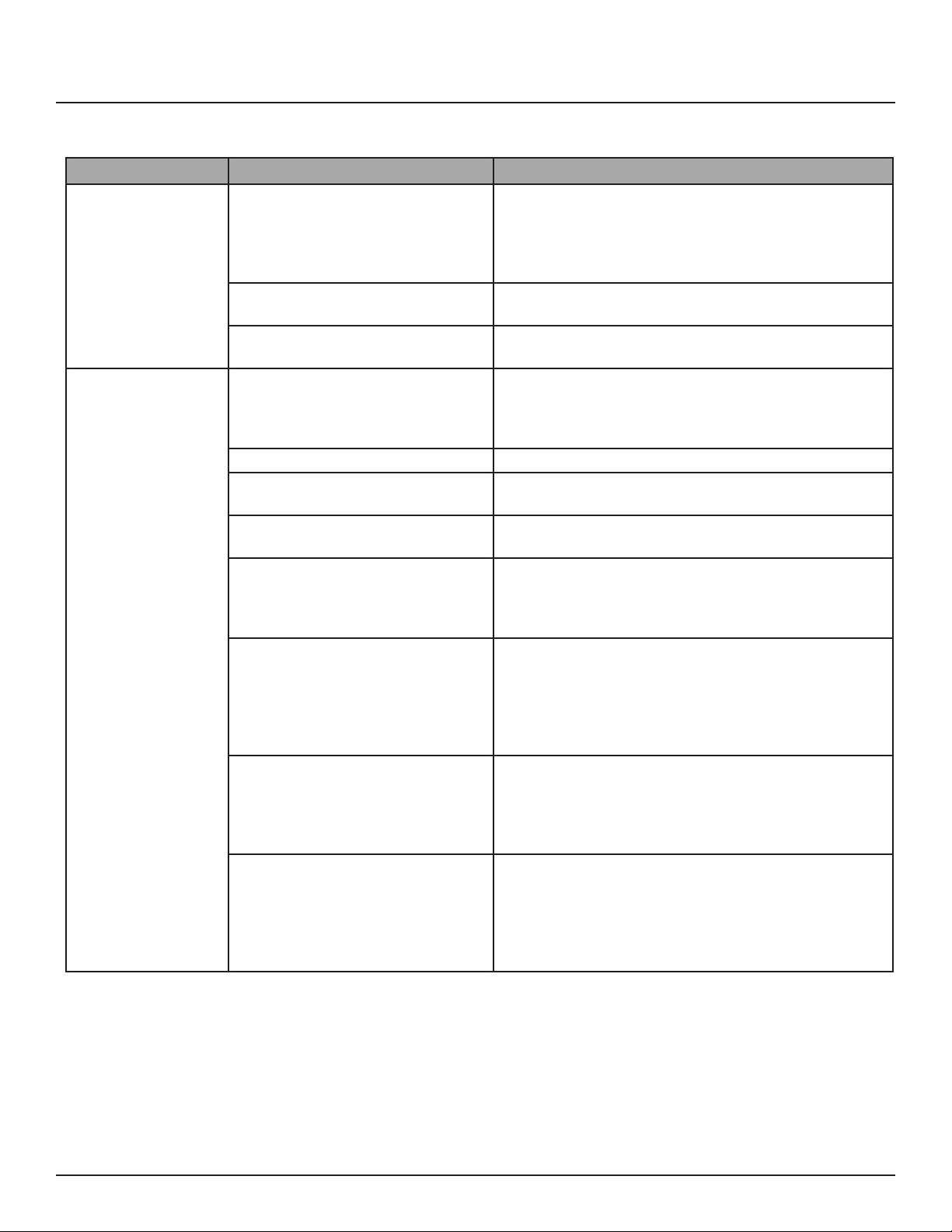
Appendix C--Troubleshooting/FAQ
Table C-1: RPC Controller Troubleshooting
Condition Possible Causes Solutions
Verify that the power supply’s LED status indicators are
ON. Make sure the 15A breaker that provides power to the
Controller LEDs and
status indicators do
not illuminate.
Motorized circuit
breaker does not
respond to input
change or does not
respond as desired.
Power supply is not energized.
Controller is not receiving power from
the power supply.
The power supply is not operating.
Controller or power supply is not
powered or operating properly.
Circuit breaker handle is OFF. Turn circuit breaker handle to ON.
Circuit breaker is tripped.
Circuit breaker Manual mode is
engaged.
Input is not connected or wired
properly.
Circuit breaker is not included in zone,
or an incorrect circuit breaker is
included in zone.
Sub-net wiring error.
Sub-net addressing error.
power supply is on. Also, verify that the power supply line
terminal is secured. Refer to the Power Supply instruction
bulletin for installation and safety information.
Make sure the 15A breaker that provides power to the
power supply is on.
Verify that the power supply is wired correctly. See Chapter
4.
Verify that both the controller and power supply are
energized by observing that all power LEDs are illuminated.
Verify that the controller is operating by
observing that the CPU LED is blinking.
Reset the circuit breaker by turning it OFF and then back
ON.
Restore the circuit breaker to Auto mode by engaging the
white button located on the face of the circuit breaker.
Verify that the input wiring is properly connected. Wiring
speci cs depend on the type of external switching
device being used. Refer to Chapter 4--Wiring for more
information.
To test all circuit breakers assigned to a zone, rst verify that
all circuit breakers are in Auto mode. Enter the Setup page
and verify that the breaker is assigned to the correct zone.
If the circuit breakers are not responding as desired, refer to
Chapter 5--Control Setup for more information on how to
add or delete a circuit breaker in a zone.
Circuit breakers in slave panels must have properly wired
sub-net communications and power. Refer to Chapter
5--Control Setup, as well as instruction bulletins for the
control bus, power supply, and slave address selector, for
more information.
Each slave panel must have a unique address. Verify that no
two slave address selectors have the same address setting
and that no slave address selector is set to zero, unless the
power supply and controller are remotely mounted with no
control bus attached. Refer to the Slave Address Selector
instruction bulletin for more information.
52
139-0498-01.52
Page 53
Appendix D
Appendix D--RPC System
Components
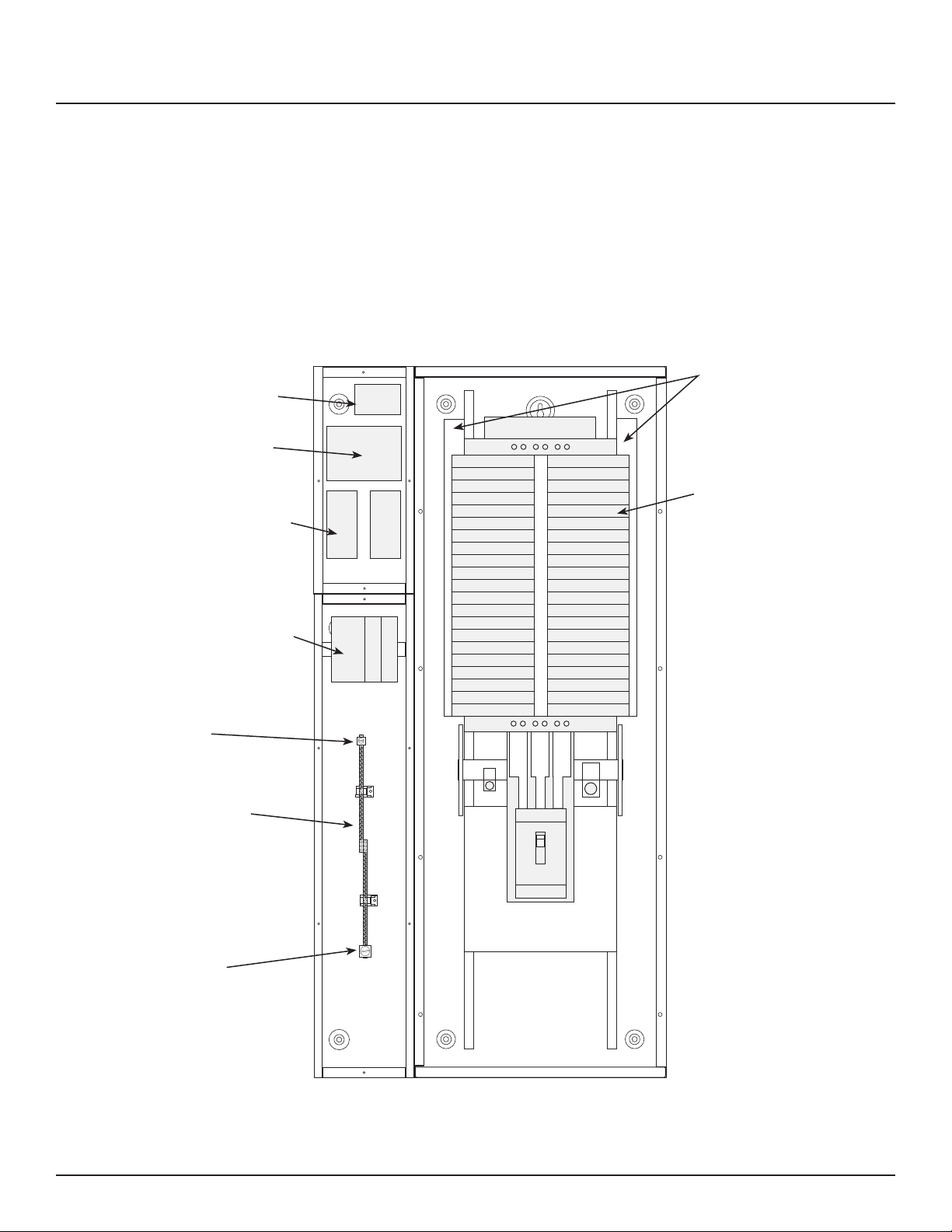
Figure D-1
Multi-Panel
Expander Board
Master Controller
Optional - Digital I/O
Expander Boards
The LynTec system consists of control buses, a panelboard,
remotely operated circuit breakers, a power supply, a bu er,
a transducer and a controller. Optional expansion boards
are available to add up to three additional panels or 16 or 32
additional I/o outputs. Figure B–1 identi es main components
which are described in this appendix.
Breaker
Control
Busses
Remotely Operated circuit
Breakers
Power Supply, Bu er
and Voltage Trans-
ducer
Feed
2/0 max.
Isolated
Technical
Ground
Bar
46 positions
14 - 4 ga.
Feed
4/0 max.
Square D NF MB Panel
with LynTec sidecars.
Outside dimensions
28” w x 56” h x 6” d
139-0500-00 RPC 341 Mechanical 9/25/08
139-0498-01.53 53
Standard RPC Main Breaker:
225 Amp - 65k AIR -
MJG32225
Main Breaker options - Part
# su x
-MHG3110, MHG3125,
-MJG3150, -MJG3175,
-MJG3200
(all 65k Amp Interrupt Rat-
ing)
Main Breaker wire:
3/0-350 kcmil Aluminum or
Copper
200% Neutral has one feed
lug that accepts two 350
kcmil wires.
Page 54
Appendix D
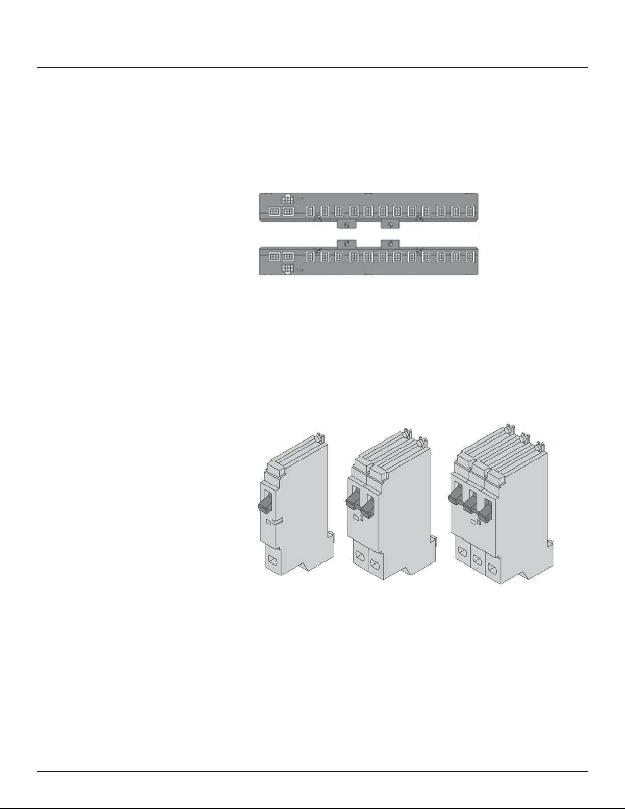
Control Bus
Figure D-2
Remotely Operated
Circuit Breakers
The control buses provide control and data monitoring for
remotely operated circuit breakers and are connected to the
power supply and controller. Installed control buses will not
interfere with the installation of standard circuit breakers into
the panelboard.
Remotely Operated Circuit Breakers provide the same
overcurrent protection as standard circuit breakers, and have an
integral operator that can remotely switch the circuit breaker
ON and OFF. The circuit breaker works with the RPC controller,
power supply, and control buses to provide a remote power
switching system in a panelboard.
Figure D-3
Part Numbers:
MBR-15
MBR-20
MBR-30
Part Numbers:
MBR-215
MBR-220
MBR-230
Part Numbers:
MBR-315
MBR-320
MBR-330
54
139-0498-01.54
Page 55
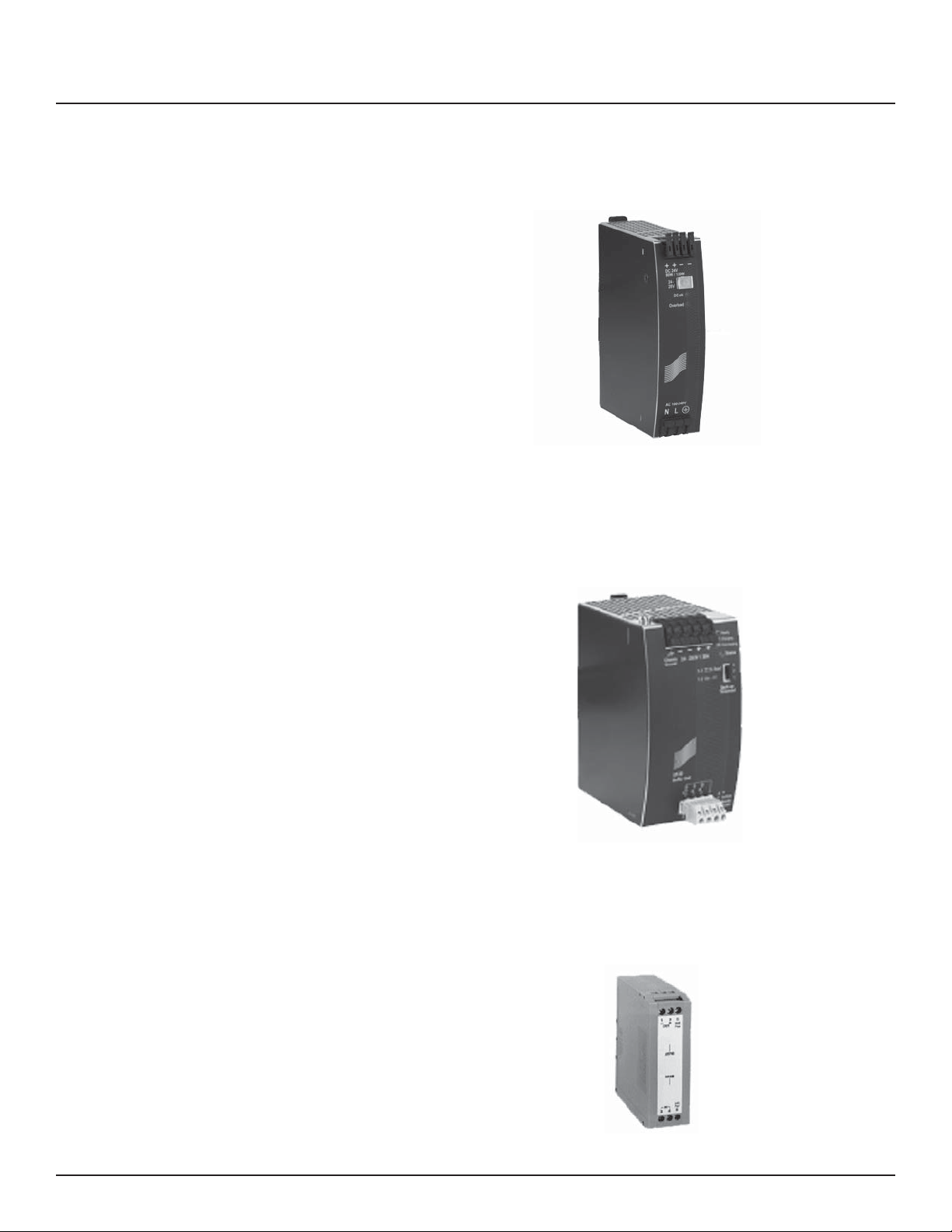
Appendix D
Power Supply The Power Supply connects to a 15A non-motorized breaker
and provides 24VDC, 3A power to the RPC controller.
Figure D-4
Bu er The bu er stores DC power and discharges it during a
brownout or power loss condition to turn o selected breakers
(up to four panels). This is a capacitive bu er and is lead and
acid free.
Figure D-5
Transducer The transducer converts incoming AC line voltage to a varying
DC output, allowing the RPC to monitor line voltage.
Figure D-6
139-0498-01.55 55
Page 56
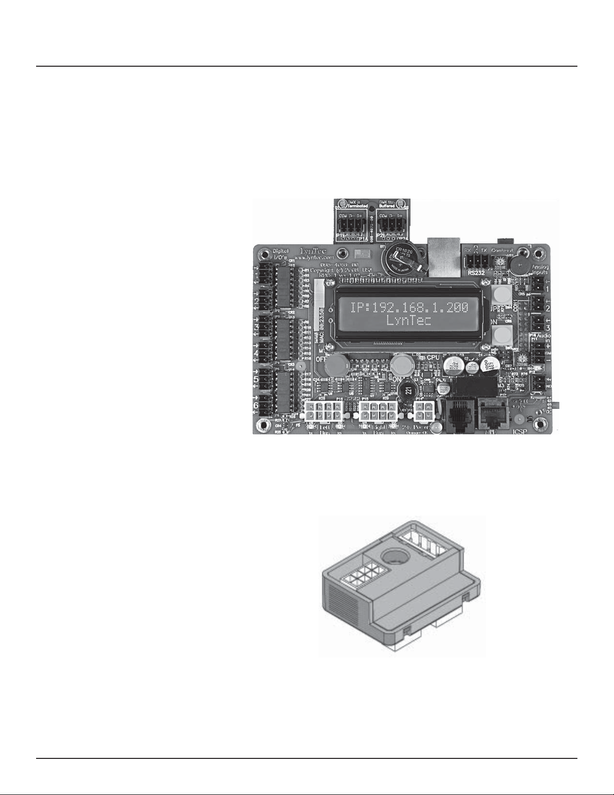
Appendix D
Controller The RPC Controller provides control logic for the
operation of a RPC system. The controller uses remotely
operated circuit breakers to control up to 167 remotely
operated branch circuits. The built in web server allows for
easy setup and operation. Also, it provides input channels for
connecting external dry-contact control devices.
Figure D-7
Slave Address Selector The slave address selector is used to set an address for a control
bus on a slave panelboard.
Figure D-8
56
139-0498-01.56
Page 57
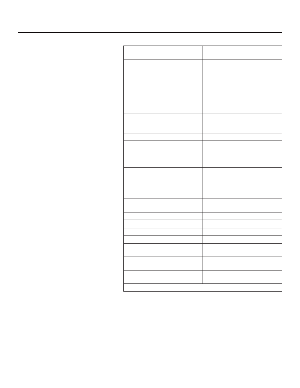
Appendix D
Inputs Six (6) independently con gurable
digital inputs/outputs
Input Types Maintained N.O.
Maintained N.C.
Momentary N.O.
Momentary N.C.
Momentary toggle
Three (3) analog inputs 0-5 or
0-10VDC
Thirty-two (32) I/O ports on optional
expander boards
Status Output 24 Vdc (60mA maximum load for all
outputs combined)
Indicator output on each I/O port
Auxiliary Power Supply 24 Vdc (200mA maximum Current)
Communication Interface RJ-45 (8P8C) Ethernet/Web Server
DMX in/thru 3-wire
RS-232 3-wire
Circuit breaker delay 0.025 sec to 8 min (selectable)
Environmental Standards Operating Temperature: –5°C to
+65°C (internal panelboard temperature)
Storage Temperature: –20°C to 85°C
Operating Humidity: 5% to 95%
Time Clock Operation during absence of power
= 30 days
Memory Retention Program: > 20 years
Standards 916 Energy Management Equipment
ESD Immunity IEC 1000, Level 4
RF Susceptibility IEC 1000, Level 3
Electrical Fast Transient Susceptibility
Electrical Surge Suceptibility--power
line
Electrical Surge Suceptibility--data
line
FCC--Part 15, Class A
IEC 1000, Level 3
IEC 1000, Level 4
IEC 1000, Level 3
139-0498-01.57 57
 Loading...