

Page 1
LynTec
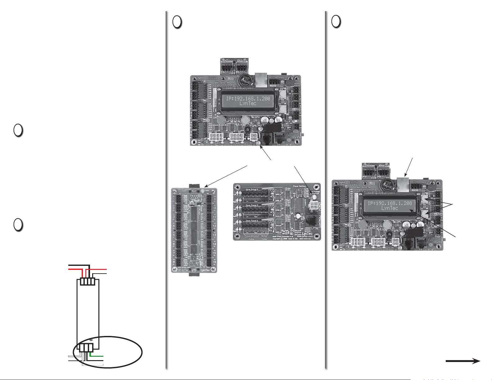
Once the 15A breaker is connected
3
and switched on, confi rm that the
orange power LEDs on each circuit
board are lit.
Connect a computer to the control
4
board using a CAT5 crossover
cable OR connect the RPC to your
network.
If connecting via a crossover cable:
RPC
Quick Start Guide
1
Make sure that the panel(s) have
been wired by a certifi ed electrician
and that there is power to the
panel(s).
Confi rm that RPS (slave) panels
are connected to the master as
indicated in the “RPC to RPS Wiring
Instructions” bulletin.
Confi rm that the electrician has
2
connected the 15A breaker in the
master panel (position 21) to the
power supply in the lower sidecar.
Power Supply DC –
Power Supply DC +
Controller Cable
Controller Cable
Control Board
With a computer directly connected
to the RPC through the Ethernet
port, change the computer’s IP
address manually so it is in the same
default IP subnet that the RPC uses:
192.168.1. The default IP address of
the RPC is 192.168.1.250.
Ethernet Port
POWER LEDS
Yellow
Buttons
LCD
Screen
Multi-Panel Expander
Board
If connecting via a network:
Transducer Neutral
Transducer Load
+ + – –
N L
Panel Ground Bar
15A Breaker
Panel Neutral Bus
I/O Expander
Board
If LEDs do not light, check chapter
4 of the RPC manual to see that
circuit boards are connected
properly.
139-0522-00 RPC Quicksheet
Connect the RPC to the network via
the Ethernet port. Push the upper
yellow button twice or until the IP
address appears on the LCD screen.
OVER
Page 2
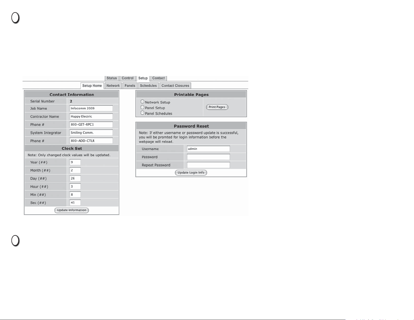
Open a web browser and access the status page via the IP address of the RPC.
5
(ex. http://192.168.1.250)
The default username is “admin” and the initial password is
“pw”.
If desired, set your username and password on the “Setup Home” page under
the “Setup” tab.
Complete the RPC setup by following the steps in Chapter 5.
6
 Loading...