

Page 1
User Manual
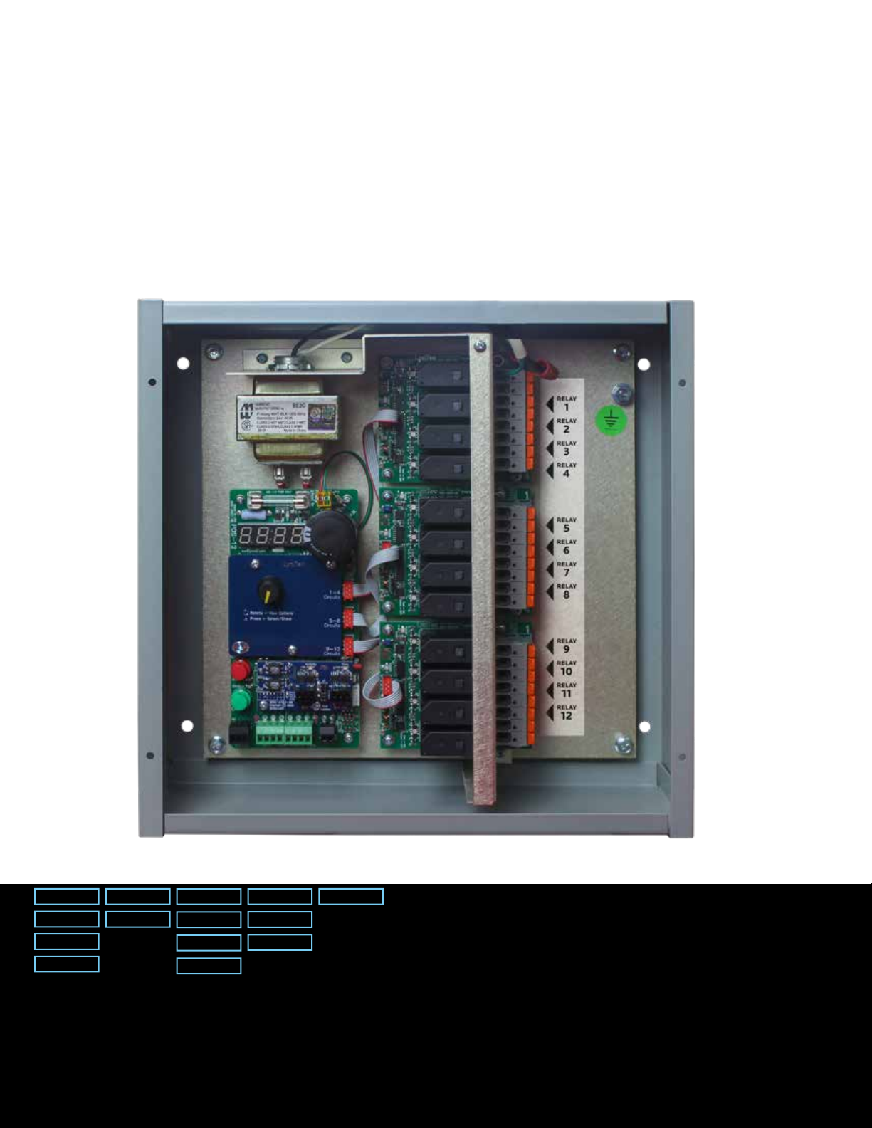
LCRP-12
Series Relay Panels
LynTec
LynTec.com I 800.724.4047
Power Control Simplied
Page 2
HAZARD CATEGORIES AND
SPECIAL SYMBOLS
Read these instructions carefully and look at the equipment to become familiar
with the device before trying to install, operate, service, or maintain it. The
following special messages may appear throughout this bulletin or on the
equipment to warn of potential hazards or to call attention to information that
clarifies or simplifies a procedure.
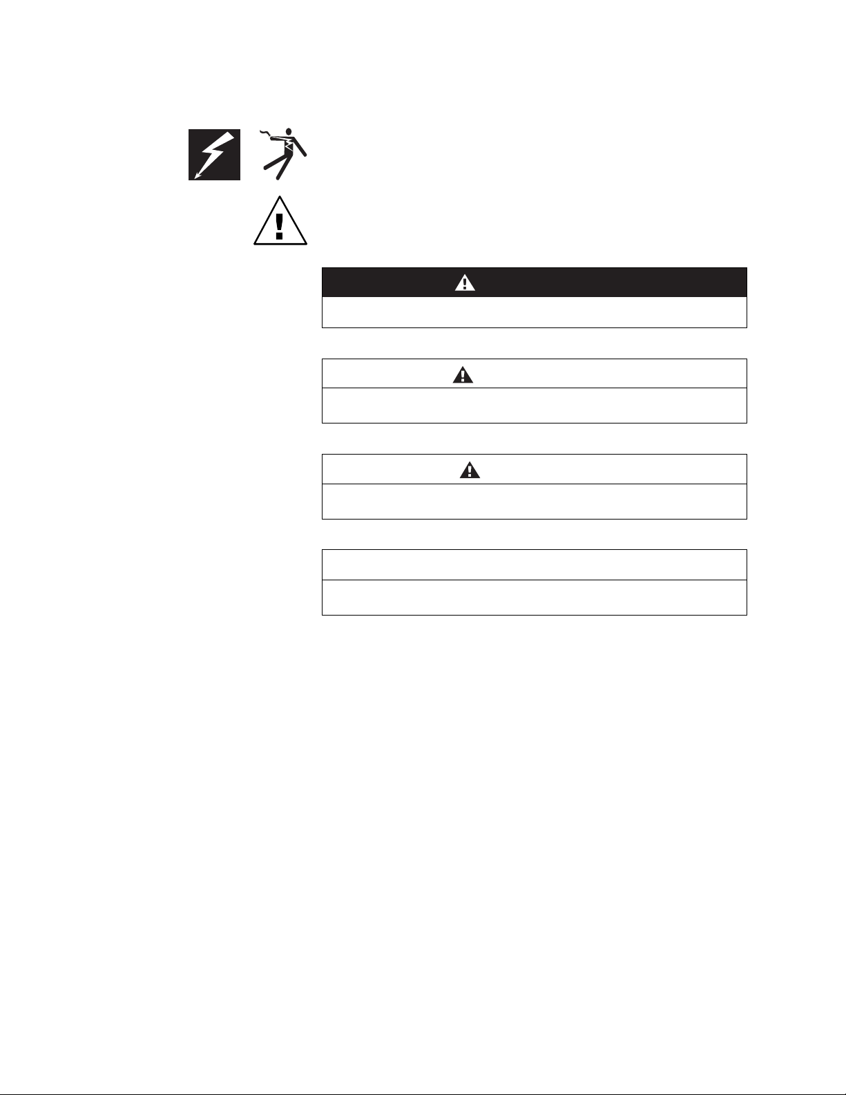
The addition of either symbol to a “Danger” or “Warning” safety label indicates
that an electrical hazard exists which will result in personal injury if the
instructions are not followed.
This is the safety alert symbol. It is used to alert you to potential personal injury
hazards. Obey all safety messages that follow this symbol to avoid possible
injury or death.
DANGER
DANGER indicates an immediately hazardous situation which, if not
avoided, will result in death or serious injury.
WARNING
WARNING indicates a potentially hazardous situation which, if not
avoided, can result in death or serious injury.
PLEASE NOTE
Class A FCC Statement
CAUTION
CAUTION indicates a potentially hazardous situation which, if not
avoided, can result in minor or moderate injury.
CAUTION
CAUTION, used without the safety alert symbol, indicates a potentially
hazardous situation which, if not avoided, can result in property damage.
NOTE: Provides additional information to clarify or simplify a procedure.
Electrical equipment should be installed, operated, serviced, and maintained
Electrical equipment should be installed, operated, serviced and main-
only by qualified electrical personnel. This document is not intended as an
tained only by qualified electrical personnel. This document is not intend-
instruction manual for untrained persons. No responsibility is assumed by
ed as an instruction manual for untrained persons. No responsibility is
Square D for any consequences arising out of the use of this manual.
assumed by LynTec for any consequences arising out of the use of this
manual.
This equipment has been tested and found to comply with the limits for a Class
Page 3

Table of Contents
LynTec
Chapter 1--Introduction ������������������������������������������������������������������������������ 1
Overview
Contents
����������������������������������������������������������������������������������������������������������
����������������������������������������������������������������������������������������������������������
1
1
Chapter 2--Safety Precautions ����������������������������������������������������������������������� 2
Chapter 3--Quick Start Guide
Introduction
������������������������������������������������������������������������������������������������������
������������������������������������������������������������������������ 3
3
Chapter 4--Wiring ������������������������������������������������������������������������������������� 4
Power Wiring
Relay Wiring
���������������������������������������������������������������������������������������������������
����������������������������������������������������������������������������������������������������
5
5
Emergency Lighting Wiring ���������������������������������������������������������������������������������� 6
Completion Contact Wiring
Chapter 5--Setup
Menu Options
������������������������������������������������������������������������������������� 8
��������������������������������������������������������������������������������������������������
���������������������������������������������������������������������������������� 6
8
Circuit Select Menu ������������������������������������������������������������������������������������������� 8
Address Menu (Addr)
On Threshold Menu (t on)
����������������������������������������������������������������������������������������� 9
����������������������������������������������������������������������������������� 9
OFF Threshold Menu (toff)
DMX Sense Menu (dSnS)
DMX Sense Timeout Menu (Sout)
Brownout Menu (bo)
����������������������������������������������������������������������������������������� 10
Emergency Lighting Menu (El)
Completion Relay Menus (C on & CoFF)
���������������������������������������������������������������������������������� 9
������������������������������������������������������������������������������������ 9
������������������������������������������������������������������������� 10
���������������������������������������������������������������������������� 10
����������������������������������������������������������������� 11
Nominal Voltage Selection Menus (VrnG & VoLt)
Emergency Relay Menus (EoCC & ELCC)
Brownout Enable/Disable (boEn)
Display Brightness (brGt)
Factory Reset (rSEt)
Information Menu (InFo)
Test Menu (teSt)
��������������������������������������������������������������������������������������������� 13
����������������������������������������������������������������������������������� 13
����������������������������������������������������������������������������������������� 13
������������������������������������������������������������������������������������ 13
������������������������������������������������������������������������� 12
���������������������������������������������������������������� 12
������������������������������������������������������� 11
LCRP-12 User Manuali
Page 4

Introduction
Chapter 1--Introduction
LynTec
OVERVIEW
CONTENTS
This bulletin explains how to install and operate the LynTec
Lighting Control (LCRP) relay panel� The LCRP-12 can
control up to 12 relays� Control signals originate externally
from a DMX source�
Each LCRP comes standard with the following components
installed:
• LCRP Controller
• Transformer
• Relay Driver to control 4, 8 or 12 relays
LCRP-12 User Manual1
Page 5

LynTec
Chapter 2--Safety Precautions
This chapter contains important safety precautions that must be followed
before attempting to install, service, or maintain electrical equipment�
Carefully read and follow the safety precautions below�
READ AND FOLLOW ALL SAFETY INSTRUCTIONS
Safety Precautions
!
HAZARD OF ELECTRIC SHOCK, EXPLOSION, OR ARC FLASH
This equipment must be installed and serviced only by
qualified electrical personnel�
• Apply appropriate personal protective equipment (PPE)
and follow safe electrical work practices� See NFPA 70E�
• Turn off all power supplying this equipment before working
on or inside equipment�
• Always use a properly rated voltage sensing device to
confirm that power is off�
• Replace all devices, doors, and covers before turning on
power to this equipment�
Failure to follow this instruction will result in
death or serious injury�
IMPORTANT SAFEGUARDS
When using electrical equipment, basic safety precautions should always be
followed including the following:
DANGER
READ AND FOLLOW ALL SAFETY INSTRUCTIONS�
• Do not use outdoors unless the enclosure is rated for outdoor use
• Do not mount near gas or electric heaters�
• Equipment should be mounted in locations and at heights where it will not
readily be subjected to tampering by unauthorized personnel�
• The use of accessory equipment not recommended by the manufacturer
may cause an unsafe condition�
• Do not use this equipment for other than intended use�
SAVE THESE INSTRUCTIONS
LCRP-12 User Manual 2
Page 6
Quick Start Guide
Chapter 3--Quick Start Guide
LynTec
INTRODUCTION
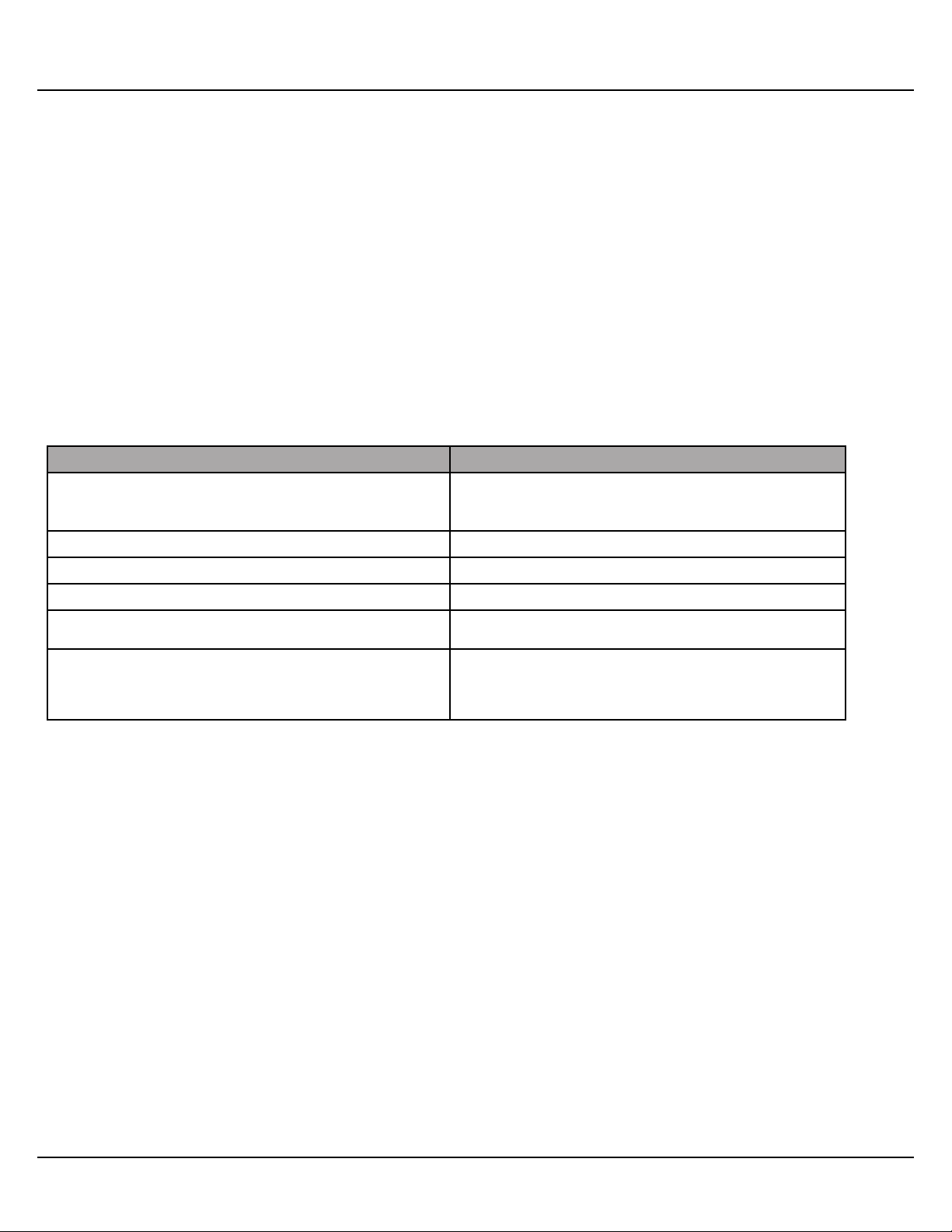
Steps Reference
1� Mount the LCRP at your preferred location as
allowed by code�
2� Wire the power transformer� Chapter 4--Wiring
3� Wire each individual circuit� Chapter 4--Wiring
4� Connect the DMX source� Chapter 4--Wiring
5� Complete the relay panel setup� Chapter 5--Control Setup
6� If your LCRP system does not operate as
expected, verify that everything is installed
and programmed correctly�
This chapter is a quick reference listing the steps necessary
to install the LCRP system� The steps in this chapter are
provided as an installation checklist� For complete installation
instructions, refer the chapter listed�
Local Electrical Code
Appendix A--Troubleshooting
LCRP-12 User Manual3
Page 7
LynTec
Chapter 4--Wiring
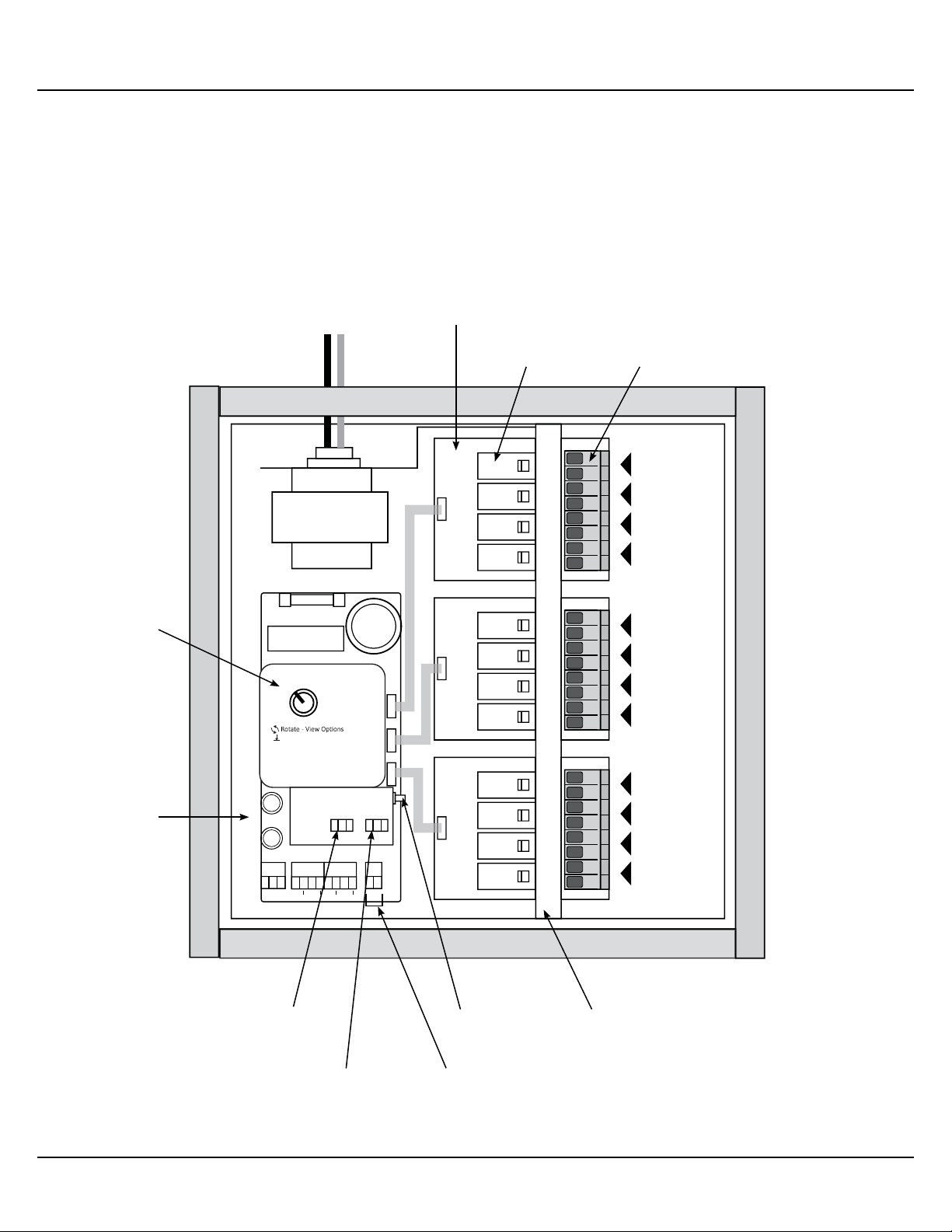
Figure 4-1: LCRP-12
24V XFMR
Relay Driver Board
Panasonic Relay
(rated up to 30A)
Wiring
Relay Connection
RELAY
1
RELAY
2
RELAY
3
RELAY
4
LCRP Controller
Test Buttons
Press - Select/Store
DMX In
RELAY
5
RELAY
LynTec
1 - 4
Circuits
5 - 8
Circuits
9 - 12
Circuits
6
RELAY
7
RELAY
8
RELAY
9
RELAY
10
RELAY
11
RELAY
12
Pilot 2
CC
CC
EO
Com
Reset Button
Voltage Barrier
OFF
ON
EL
Pilot
Com
DMX Thru
Outbound Relay
Connection
LCRP-12 User Manual 4
Page 8
Wiring
LynTec
POWER WIRING
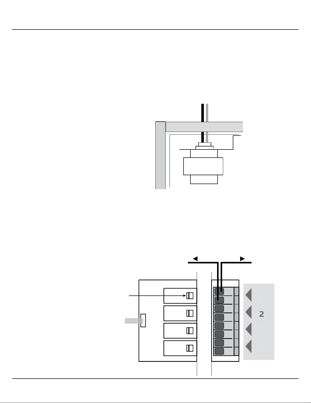
Figure 4-2: 24V Power Transformer
To initially wire the LCRP, connect the power breaker in your
panel to the transformer in the LCRP�
Connect to suitable
unswitched power source
24V XFMR
RELAY WIRING
Figure 4-3: Relay Driver Board
Manual Override
To wire individual relays, bring the hot from the breaker to
the first terminal for the desired relay� Then run another
conductor from the second relay terminal to the load�
From circuit
breakerTo load
Switch
LCRP-12 User Manual5
Page 9
LynTec
Wiring
Emergency Lighting Wiring
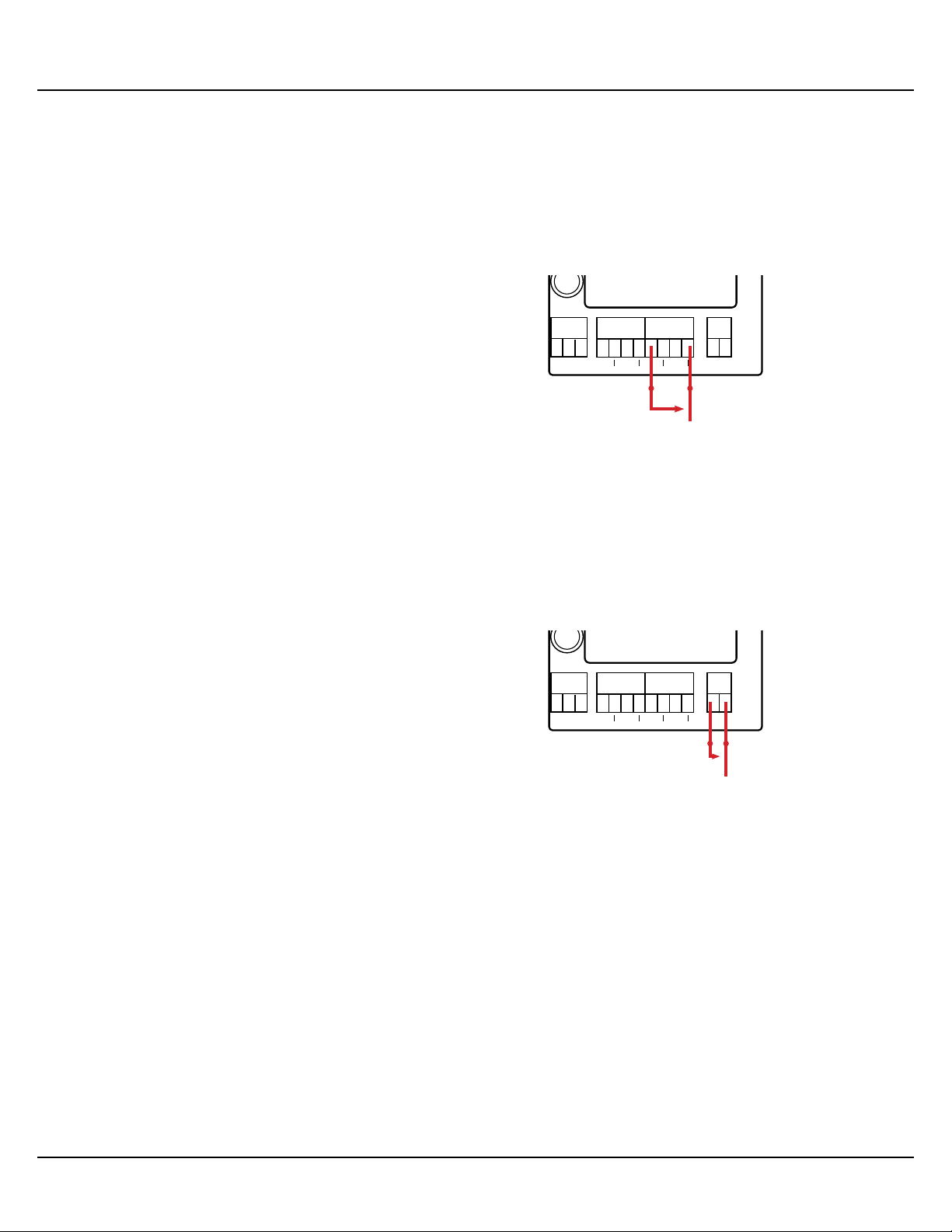
Figure 4-8: Wiring for Emergency
Lighting
Completion Contact Wiring
From the fire alarm unit or latching Emergency Lighting
switch, wire the Normally Open (NO) contacts to the “EL” and
“Com” positions on the LCRP Controller�
ON
ON
Pilot
OFF
Com
EL
Pilot 2
EO
Com
CC
CC
Normally Open
Emergency Contacts
From the desired unit, wire the Normally Open (NO) contacts
to the “CC” and “CC” positions on the LCRP Controller�
Figure 4-9: Wiring for Completion
Contacts
ON
ON
Pilot
OFF
Com
EL
Pilot 2
CC
CC
EO
Com
Normally Open Contacts
LCRP-12 User Manual 6
Page 10

Wiring
LynTec
INITIAL POWER UP
PROCEDURE
With the circuit breaker panel door open and breakers visible,
turn on the Controller Power 15 Amp circuit breaker�
The red “Status” LED should illuminate on the LCRP
Controller and “Lyntec LCRP-12” will scroll across the screen�
Use the red and green test buttons to test relay operation�
Please note that the test buttons and normal sequencing
signals are disabled when a DMX signal is detected regardless
of DMX sense settings�
EO/EL will override DMX signal settings, but individual circuit
settings allow customization of the response� BO is enable by
default, but can be disabled in the normal manner�
LCRP-12 User Manual7
Page 11
LynTec
Setup
Chapter 5--Setup
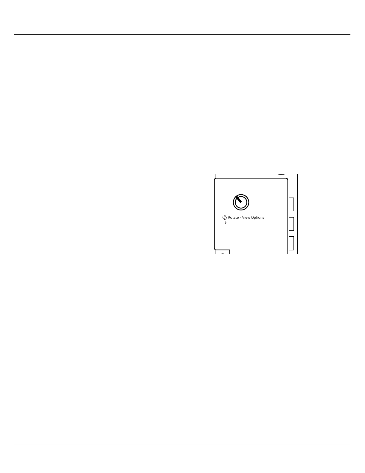
Figure 5-1: LCRP Controller Dial
LCRP-12 setup is achieved via a dial on the LCRP Controller�
The dial is rotated to view options and pressed to select and
store options� The dial can rotate left or right and also be
pressed in for menu selection and control� The screen will
timeout after 30 seconds and clear anything not saved�
Note: It is advised to not have DMX signal active during
setup� Having a DMX signal active during setup reduces the
responsiveness of the dial�
LynTec
1 - 4
Circuits
Press - Select/Store
5 - 8
Circuits
MENU OPTIONS
Circuit Select Menu
9 - 12
Circuits
The Circuit Select Menu will appear any time changes are
made to individual circuits� All circuit LEDs will go Green
except the selected circuit which will alternate between red
& green�
When the desired circuit has been selected, press the dial
to move to the next option for that circuit�
On menus where the circuit ON/OFF is selected, green
designates OFF & red designates ON�
To save changes, press the dial in for 2 seconds to ensure
all changes are saved to memory� “SAVd” will display on
the screen when saving is complete�
LCRP-12 User Manual 8
Page 12

Setup
LynTec
Address Menu (Addr)
On Threshold Menu (t on)
Changes the starting address for the sequential DMX
addressing� Valid range is from 1-512 minus the number
of circuits� For example a 12 circuit LCRP-12 would have
the highest valid starting address of 501� The address
is changed one digit at a time� Least significant first to
most significant� Encoder press will move to the next
digit until all digits are complete and saves the new
address� Default address is 001�
Changes the the threshold level for DMX to turn the circuit
ON� The on threshold is limited in range from 145 to 239�
The default value is 192 (75%)�
The threshold is changed one digit at a time� Least
significant first to most significant� Encoder press will move
to the next digit until all digits are complete and saves the
new threshold level�
OFF Threshold Menu (toff)
DMX Sense Menu (dSnS)
Changes the the threshold level for DMX to turn the circuit
OFF� The on threshold is limited in range from 17 to 111�
The default value is 64 (25%)�
The threshold is changed one digit at a time� Least
significant first to most significant� Encoder press will move
to the next digit until all digits are complete and saves the
new threshold level�
This menu enables or disables DMX sense� This will cause
ALL circuits to turn ON when a DMX signal is detected�
Circuits will turn OFF based on the next timeout setting�
There is no individual circuit control when DMX Sense is
enabled�
LCRP-12 User Manual9
Page 13

LynTec
Setup
DMX Sense Timeout Menu (Sout)
Brownout Menu (bo)
DMX Sense Timeout is the time without a DMX signal
before ALL circuits are automatically turned OFF�
Default is 5 minutes� Options are 1, 2, 5, 10 minutes� Press
to save the selection and return to main menu�
This feature changes the circuit state for circuits during a
under-voltage (brownout) or over-voltage condition� The
default setting is all circuits set to turn off during either
voltage condition�
Pressing the dial will activate the Circuit Select Menu� The
current setting for the selected circuit will be displayed�
Press the dial to change the state� Rotating left will select
“OFF” and right will select “ON”
Emergency Lighting Menu (El)
Press to save the selection and return to Circuit Select Menu�
When all changes to individual circuits have been made�
Press to save the selection and return to main menu�
This feature allows you to select which individual circuits
should turn on in the event of an emergency� This feature is
disabled by default�
Pressing the dial will activate the Circuit Select Menu� The
current setting for the selected circuit will be displayed�
Press the dial to change the state� Rotating left will select
“OFF” and right will select “ON”
Press to save the selection and return to Circuit Select Menu�
When all changes to individual circuits have been made�
Press to save the selection and return to main menu�
LCRP-12 User Manual 10
Page 14
Setup
LynTec
Completion Relay Menus
(C on & CoFF)
Nominal Voltage Selection Menus
(VrnG & VoLt)
These two menus allow you to select which individual circuits
trigger the completion relay� The default ON circuit is the
last circuit and the default OFF circuit is the first circuit�
Pressing the dial will activate the Circuit Select Menu� Rotate
the dial to select the desired circuit� The current setting
for the selected circuit will be displayed� Press the dial to
change the state�
Press to save the selection and return to Circuit Select Menu�
When all changes to individual circuits have been made�
Press to save the selection and return to main menu�
These menus allow you to set the nominal voltage for undervoltage (brownout) or over-voltage monitoring� Do not
change this setting without changing out the transformer
hardware�
The VrnG menu sets the voltage range� Exact voltages are
selected in the next menu� Press to open the VrnG menu
and turn the dial to select 120C, 240V or 277V as the voltage
range� The factory setting is based on the model ordered�
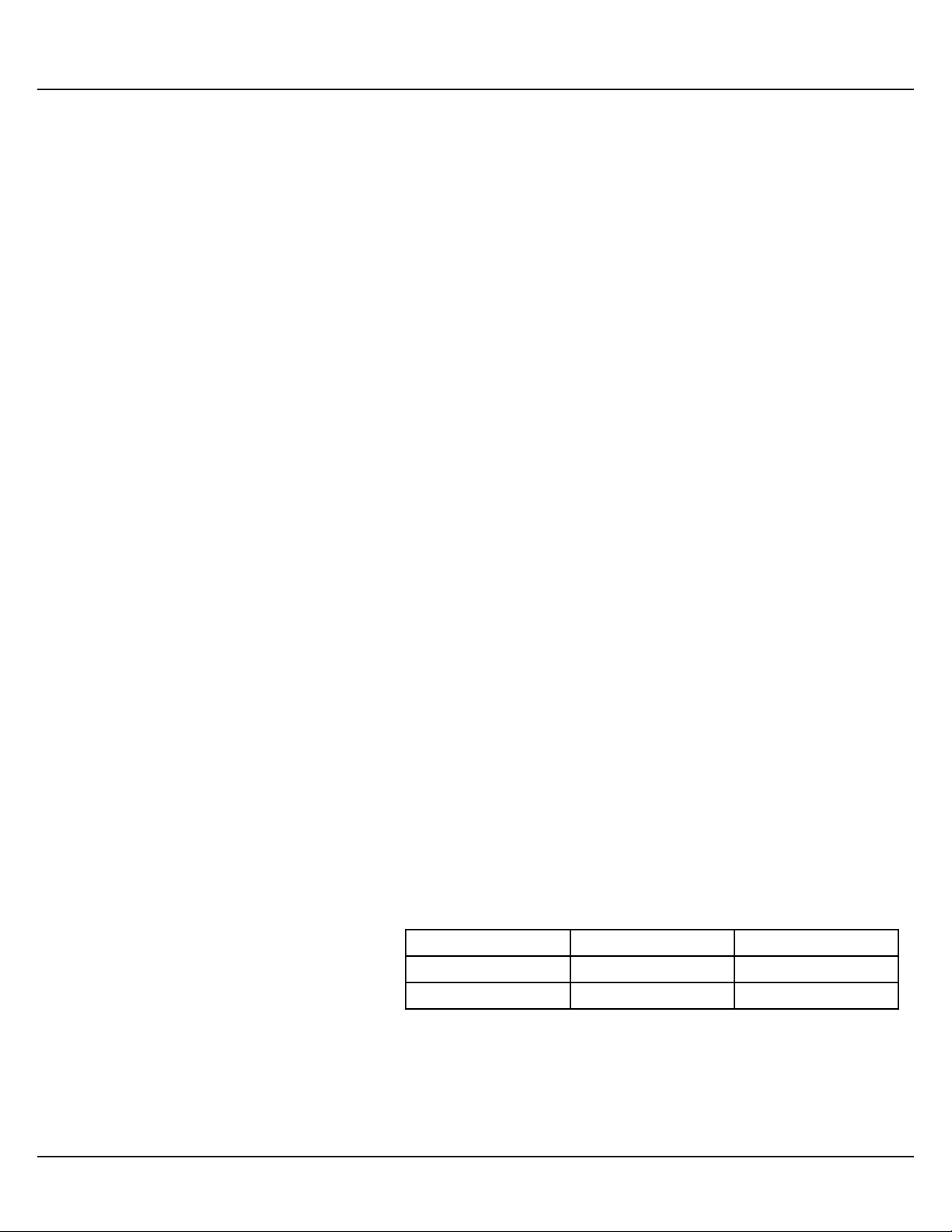
Table 5-1: Voltage Settings
Press to save the selection and return to main menu�
The VoLt menu allows to refine the nominal voltage within
the selected range� For example, in the 120V range, you may
choose any nominal voltage between 100V - 130V in 1 volt
increments� See table 5-1 for ranges and increments�
Press to save the selection and return to main menu�
Setting Range Increment
120V 100V - 130V 1 volt
240V 200V - 260V 5 volts
LCRP-12 User Manual11
Page 15

LynTec
Setup
Emergency Relay Menus
(EoCC & ELCC)
Brownout Enable/Disable (boEn)
The default input type for EL and EO features is Normally
Open� You may change the type to Normally Closed in these
menus�
Press the dial to display the current setting� Rotate to
change the setting�
Press to save the selection and return to main menu�
This feature allows you to enable or disable the brownout
(under or over-voltage) protection� The default setting is
ENABLED� To disable, press to open the menu, then rotate�
Press to save the selection and return to main menu�
PLEASE NOTE: If brownout is disabled, the start up voltage
check is also disabled� The normal start time requirement
for this is 5 seconds� Control is only possible after this check
is complete� Disabling Brown out removes this start up time
check, enabling it conversely ensures that voltage is good
before making changes�
LCRP-12 User Manual 12
Page 16

Setup
LynTec
Display Brightness (brGt)
Factory Reset (rSEt)
This menu changes the brightness of the display� The screen
will not blink, but left/right will decrease/increase the
brightness in real time�
Press to save the selection and return to main menu�
To reset the LCRP-12 to factory settings press the dial to
confirm�
CAUTION: This action restores everything to default
configuration� All settings will be lost� The LCRP-12
will automatically restart�
Information Menu (InFo)
Test Menu (teSt)
This menu shows the current firmware version of the LCRP12�
Press to return to main menu�
When pressed, circuit 1 will turn on� Turn the dial to the right
will turn OFF circuit 1 and then turn ON circuit 2 at a half
second interval� This will repeat for as many circuits as are
installed� Turn the dial to the left to reverse the circuit OFF /
ON sequence�
This will NOT time out� A second press of the encoder button
is required to end the TEST mode�
Press to return to main menu�
LCRP-12 User Manual13
 Loading...