


M1507_EVB User Manual
M1507_EVB User Manual
Smart Module Series
Version: V1.2
Date: 2016-10-28
Shanghai Mobiletek Communication Ltd
Copyright © Shanghai Mobiletek Communication Ltd 0

M1507_EVB User Manual
LYNQ
CONDENTIAL
Notice
Some features of the product and its accessories described herein rely on the software installed,
capacities and settings of local network, and therefore may not be activated or may be limited by local
network operators or network service providers.Thus, the descriptions herein may not exactly match
the product or its accessories which you purchase.Shanghai Mobiletek Communication Ltd reserves
the right to change or modify any information or specifications contained in this manual without prior
notice and without any liability.
Copyright
This document contains proprietary technical information which is the property of Shanghai Mobiletek
Communication Ltd. copying of this document and giving it to others and the using or communication
of the contents thereof, are forbidden without express authority. Offenders are liable to the payment of
damages. All rights reserved in the event of grant of patent or the registration of a utility model or
design. All specification supplied herein are subject to change without notice at any time.
DISCLAIMER
ALL CONTENTS OF THIS MANUAL ARE PROVIDED “AS IS”. EXCEPT AS REQUIRED BY
APPLICABLE LAWS, NO WARRANTIES OF ANY KIND, EITHER EXPRESS OR IMPLIED,
INCLUDINGBUT NOT LIMITED TO, THE IMPLIED WARRANTIES OF MERCHANTABILITY AND
FITNESS FOR A PARTICULAR PURPOSE, ARE MADE IN RELATION TO THE ACCURACY,
RELIABILITY OR CONTENTS OF THIS MANUAL.TO THE MAXIMUM EXTENT PERMITTED BY
APPLICABLE LAW, IN NO EVENT SHALL SHANGHAI MOBILETEKCOMMUNICATION LTD BE
LIABLE FOR ANY SPECIAL, INCIDENTAL, INDIRECT, OR CONSEQUENTIAL DAMAGES, OR
LOSS OF PROFITS, BUSINESS, REVENUE, DATA, GOODWILL SAVINGS OR ANTICIPATED
SAVINGS REGARDLESS OF WHETHER SUCH LOSSES ARE FORSEEABLE OR NOT.
Copyright © Shanghai Mobiletek Communication Ltd 1
M1507_EVB User Manual
Date
Version
Modify records
Author
2016-07-08
V1.0
Initial version
Rongchun.Dong
2016-08-22
V1.1
Delete AV_IN
Rongchun.Dong
2016-10-28
V1.2
The machine pictures and instructions.
Functional testing of instructions
Rongchun.Dong
LYNQ
CONDENTIAL
Version History
Copyright © Shanghai Mobiletek Communication Ltd 2
M1507_EVB User Manual
LYNQ
CONDENTIAL
CONTENT
1. Overview ................................................................................................................................................ 4
2. M1507_EVB and Interface Introduction ................................................................................................ 4
3. M1507_EVB External Device and Functional Test ................................................................................ 7
3.1 Power Supply ...................................................................................................................................... 7
3.2 Power Key and Hardware Reset ......................................................................................................... 7
3.3 UART Interface .................................................................................................................................... 8
3.4 SIM Card and TF Card ........................................................................................................................ 8
3.5 Audio interface ................................................................................................................................... 10
3.6 USB ................................................................................................................................................... 11
3.7 Functional Test .................................................................................................................................. 11
3.7.1 Machine test ............................................................................................................................... 11
3.7.2 A single test ................................................................................................................................ 13
Copyright © Shanghai Mobiletek Communication Ltd 3
M1507_EVB User Manual
LYNQ
CONDENTIAL
1. Overview
This document defines and specifies the usage of M1507_EVB. You can know how to use
M1507_EVB and tools from this document.
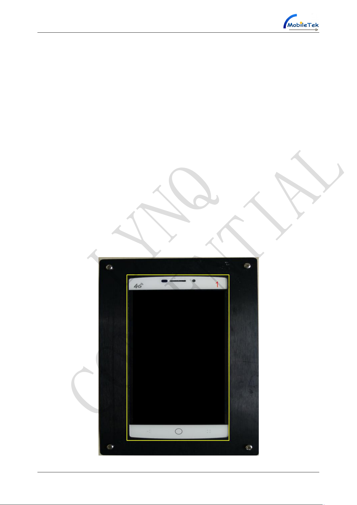
2. M1507_EVB and Interface Introduction
M1507_EVB is designed for the development of M1507 module to help developers to debug and test
M1507 module. The following figure shows the label of the main functions of M1507_EVB.This article
will describe the various parts of its functions in later chapters.
Copyright © Shanghai Mobiletek Communication Ltd 4

M1507_EVB User Manual
LYNQ
CONDENTIAL
Figure 1 M1507_EVB FRONT
Figure 2 M1507_EVB REAR
Figure 3 M1507_EVB PLANFORM
Figure 4 M1507_EVB REAR UPWARD
Copyright © Shanghai Mobiletek Communication Ltd 5

M1507_EVB User Manual
1.LCD(HD1280*720)
2.Speaker
3. Flashlight
4.Sub Camera(2MP)
5.Flashlight
6.Main Camera(5MP)
7.USB Interface
8.UART Interface
9.Battery
10. Headset Interface
11.SIM1
12.TF Card
13.SIM2
14. Main MIC
15.POWKEY
16.SYSRSTB
17.Volume+
18. Volume+
19. Volume-
20. Sub MIC
LYNQ
CONDENTIAL
Figure 5 M1507_EVB LEFT VIEW
Figure 6 M1507_EVB PLANFORM RIGHT VIEW
Table 1 Label Illustrate
Copyright © Shanghai Mobiletek Communication Ltd 6

M1507_EVB User Manual
LYNQ
CONDENTIAL
3. M1507_EVB External Device and
Functional Test
3.1 Power Supply
Such as figure 7, “9,Battery”,3.50-4.35V battery power supply.
Figure 7 M1507_EVB Battery
3.2 Power Key and Hardware Reset
Such as figure 8,Pressing the “15,POWKEY” key of the SOM with 3 to 5 seconds,it can open the
SOM(System on Module). In the boot state, pressing "15, POWKEY" can enter standby mode. In the
boot state, pressing "15, POWKEY" 2 to 3 seconds can choose to Shutdown/Restart SOM. If you
press the “16,SYSRSTB” key, you can make the SOM power off.
Figure 8 POWKEY And SYSRSTB
Copyright © Shanghai Mobiletek Communication Ltd 7

M1507_EVB User Manual
Note: In the boot state, press the SYSRSTB is power off, not restart;
Long press POWKEY for about 12 seconds to shutdown and restart the SOM.
LYNQ
CONDENTIAL
3.3 UART Interface
Such as figure 9, The M1507_EVB has a set of "8, UART Interface ". M1507_EVB can be connected
via a serial port line with PC or other devices for a serial port communication. The default support
Demo board 115200 baud rate.
Figure 9 M1507 UART Interface
3.4 SIM Card and TF Card
The M1507_EVB to provide two SIM interfaces and a TF interfaces, such as figure 10:
The "11, SIM1 ", support 4G FDD-LTE,TDD-LTE,CDMA/EVDO network,3G WCDMA, TD-SCDMA
network and GSM 2G network.
The "13, SIM2" , support 4G FDD-LTE,TDD-LTE network,3G WCDMA, TD-SCDMA network and
GSM 2G network.
The "12, TF Card" can support up to 128GB.
Copyright © Shanghai Mobiletek Communication Ltd 8

M1507_EVB User Manual
Note: When use less than 32 GB TF card, there is no compatibility problems. If TF cards
more than 32GB have been formatted by Windows system, they should be formatted
again by Android system before used. Under the Android system format of TF card, have
no this problem.
Note: SIM1 and SIM2 does not support hot plug SIM card;
SIM1 and SIM2 can’t support using 3G network at the same time. When the SIM1
uses 3G network, SIM2 can automatically switch to 2G network. When set the SIM
2 to use 3G network, SIM 1 switch to 2G network; SIM1 and SIM2 can support both
2G network.
SIM1 and SIM2 can’t support using 4G network at the same time. When the SIM1
uses 4G network, SIM2 can automatically switch to 2G network. When set the
SIM2 to use 4G network, SIM1 switch to 2G network; SIM1 and SIM2 can support
both 2G network.
LYNQ
CONDENTIAL
Figure 10 SIM Card And TF Card
Copyright © Shanghai Mobiletek Communication Ltd 9

M1507_EVB User Manual
LYNQ
CONDENTIAL
3.5 Audio interface
The audio interfaces include one headset interface and one SPK interface, two MIC interfaces:
Such as figure 11“10,Headset Interface”, can support the 3.5 mm earphone interface.
Figure 11 3.5mm Headset Interface
When pull out headphones, the M1507_EVB default use figure 12 "2, speaker".
Figure 12 Speaker
The M1507_EVB supports two MIC. There is noise reduction in handset mode, not in hands-free
mode. It is only stereo recording in recording mode.
Copyright © Shanghai Mobiletek Communication Ltd 10

M1507_EVB User Manual
LYNQ
CONDENTIAL
Figure 13 MIC Interface
3.6 USB
Such as figure 14, the 1507_EVB has a "7, micro USB interface" for USB download, Log capture,
OTG function and charge the battery.
Figure 14 USB Interface
3.7 Functional Test
In dial-up, input "* #*# 88 #* # *" and enter the test mode.
3.7.1 Machine test
Such as figure 15, clickable item at the top of the engine test, began to test.
Copyright © Shanghai Mobiletek Communication Ltd 11

M1507_EVB User Manual
LYNQ
CONDENTIAL
Figure 15 Test mode interface
Such as figure 16, if the factory of the test item is success, the test items displayed as blue. If the
function of the test item is failed, the test items shown in red.
Figure 16
Such as figure 17, in the process of test, touch the prompt dialog box to choose "success" or "failed",
and then enter the next test.
Copyright © Shanghai Mobiletek Communication Ltd 12

M1507_EVB User Manual
LYNQ
CONDENTIAL
Figure 17
3.7.2 A single test
Choose one option in individual test. Such as figure 18, click the Success interface if TF card is
normal.
Figure 18
Such as figure 19, if the test passes, the test items according to blue. If the test is failed, the test items
shown in red.
Copyright © Shanghai Mobiletek Communication Ltd 13

M1507_EVB User Manual
LYNQ
CONDENTIAL
Figure 19
Copyright © Shanghai Mobiletek Communication Ltd 14
 Loading...