

Lyngdorf Audio TDA 2200 User Manual
TDA 2200
RoomPerfect™
True Digital Amplifier
Owner’s Manual

1

Table of Contents
1. WARNINGS .............................................................................................................................................. 5
a. Explanation of graphical symbols ......................................................................................................... 5
i. Exclamation symbol ......................................................................................................................... 5
ii. Lightning symbol .............................................................................................................................. 5
b. Important safety instructions................................................................................................................. 6
2. Unpacking the TDA 2200 ........................................................................................................................ 7
a. Accessories .......................................................................................................................................... 7
b. Operating Voltage................................................................................................................................. 8
3. Product Registration .............................................................................................................................. 8
4. Introduction ............................................................................................................................................. 9
5. Front Panel ............................................................................................................................................ 10
a. Controls .............................................................................................................................................. 10
b. Display Indicators ............................................................................................................................... 11
6. Rear Panel.............................................................................................................................................. 12
7. Remote Control ..................................................................................................................................... 13
8. Menu System ......................................................................................................................................... 14
a. RoomPerfect™ ................................................................................................................................... 15
b. Voicing ................................................................................................................................................ 15
c. Crossover ........................................................................................................................................... 15
d. Delay................................................................................................................................................... 16
e. ADC Level - Otional ............................................................................................................................ 17
f. Communication................................................................................................................................... 17
g. Trigger Set-up..................................................................................................................................... 18
h. Remote Control................................................................................................................................... 18
i. Display ................................................................................................................................................ 18
j. Volume................................................................................................................................................ 19
k. Advanced set-up................................................................................................................................. 20
9. RoomPerfect™ ...................................................................................................................................... 21
a. The Guided Set-up – a Quick Guide .................................................................................................. 22
b. Setting the measurement volume level .............................................................................................. 23
c. Focus Measurement ........................................................................................................................... 25
d. Room Measurements ......................................................................................................................... 26
e. Adding more room measurements ..................................................................................................... 27
f. Calculation of Focus 1 and Global Filters........................................................................................... 28
3

10.
RoomPerfect™ Advanced Menu ..................................................................................................... 29
a. Selected Position ................................................................................................................................ 29
b. Adding a New Focus Position............................................................................................................. 29
c. Adding a New Room Position ............................................................................................................. 31
d. RoomKnowledge Index ...................................................................................................................... 32
e. RoomCorrection Index........................................................................................................................ 32
11.
Daily Use of RoomPerfect™ ............................................................................................................ 33
a. Global Listening .................................................................................................................................. 33
b. Focus Listening................................................................................................................................... 33
12.
RoomPerfect™ Troubleshooting .................................................................................................... 34
a. No microphone connected.................................................................................................................. 34
b. Fault - No signal.................................................................................................................................. 34
c. Fault - Signal clipping ......................................................................................................................... 35
d. Fault - Low signal................................................................................................................................ 35
13.
Software............................................................................................................................................. 36
14.
Connectors ........................................................................................................................................ 37
a. Mains Connector................................................................................................................................. 37
b. Loudspeaker Connectors ................................................................................................................... 37
15.
Optional AD Converter Board ......................................................................................................... 38
a. Balanced inputs .................................................................................................................................. 38
b. Unbalanced inputs .............................................................................................................................. 38
c. Trigger connector................................................................................................................................ 38
16.
Cleaning and Maintenance .............................................................................................................. 38
17.
Technical Specifications.................................................................................................................. 39
a. Audio................................................................................................................................................... 39
b. Protection............................................................................................................................................ 40
c. Mains .................................................................................................................................................. 40
d. Trigger ................................................................................................................................................ 40
e. Mechanical.......................................................................................................................................... 40
18.
Technical Assistance ....................................................................................................................... 41
a. Support ............................................................................................................................................... 41
19.
Appendix ........................................................................................................................................... 42
a. Menu Tree .......................................................................................................................................... 42
b. Voicing Curves.................................................................................................................................... 43
4
1. WARNINGS
CAUTION: TO REDUCE THE RISK OF ELECTRICAL SHOCK,
DO NOT REMOVE COVER. NO USER-SERVICEABLE PARTS
INSIDE. REFER SERVICING TO QUALIFIED PERSONNEL.
TO REDUCE RISK OF FIRE OR ELECTRIC SHOCK, DO NOT EXPOSE THIS APPLIANCE TO RAIN OR MOISTURE.
RISK OF ELECTRICAL
SHOCK. DO NOT OPEN
CAUTION
a. Explanation of graphical symbols
i.
Exclamation symbol
The exclamation point within an equilateral triangle is intended to alert the user
to the presence of important operating and maintenance (servicing) instructions
in the literature accompanying the product.
ii.
Lightning symbol
The lightning with arrowhead symbol within an equilateral triangle is intended to
alert the user to the presence of uninsulated “Dangerous Voltage” within the
products’ enclosure that may be of sufficient magnitude to constitute a risk of
electrical shock to a person.
5

b. Important safety instructions
Do not block any ventilation openings. Install in accordance with the manufacturer’s
heat sources such as radiators, heat registers, stoves, or other
type plug has
our safety. If the
provided plug does not fit into your outlet, consult an electrician for replacement of the
Protect the power cord from being walked on or pinched, particularly at plugs,
they exit from the apparatus. Do not use
Use only with cart, stand, bracket, or table specified by the manufacturer, or sold with the
atus. When a cart is used, use caution when moving the cart/apparatus
To completely disconnect this apparatus from the AC Mains, disconnect the power
Do not connect any output from the amplifier to any other amplifier's output or any other
this apparatus to dripping or splashing and ensure that no objects filled
To avoid electrical shock, make sure that no conductive part of the loudspeaker wiring is
s operating. Do not connect loudspeakers with uninsulated
Refer all servicing to qualified service personnel. Servicing is required when the
supply cord or plug
are damaged, liquid has been spilled or objects have fallen into the apparatus, the
apparatus has been exposed to rain or moisture, does not operate normally or has been
1: Read these instructions carefully before installing or operating this apparatus.
2: Keep these instructions.
3: Heed all warnings.
4: Follow all instructions.
5: Do not use this apparatus near water.
6: Clean only with a dry cloth.
7:
instructions.
8: Do not install near any
apparatus that produce heat.
9: Do not defeat the safety purpose of the grounding-type plug. A grounding-
two pins and a third grounding prong. The third prong is provided for y
obsolete outlet.
10:
convenience receptacles, and the point where
this unit with a damaged cord or plug.
11: Only use attachments and accessories specified by the manufacturer.
12:
appar
combination to avoid injury from tipping over.
13: Unplug this apparatus during lightning storms or when unused for long periods of time.
14: Connect only to the proper mains voltage.
15:
supply cord plug from the AC receptacle.
16:
voltage source.
17: Do not expose
with liquids, such as vases, are placed on the apparatus.
18:
exposed while the amplifier i
terminals to the amplifier.
19:
apparatus has been damaged in any way, such as when the power-
dropped.
6

2. Unpacking the TDA 2200
ON AND PACKING MATERIALS for future use or in the
unlikely event that the unit needs servicing. If this unit is shipped without the
Carefully remove the unit and accessory kit from the carton, visually check for shipping
damage. Contact both the shipper and Lyngdorf Audio immediately if the unit bears any
sign of damage from mishandling. All Lyngdorf Audio equipment is carefully inspected
before leaving our factory.
KEEP SHIPPING CART
original packing, damage could occur and void the warranty.
a. Accessories
You should find the following in the accessory kit:
1. One mains cord
2. Customer registration form
3. Remote control
4. Programming cable
5. Microphone
6. Microphone stand with Mic clamp
7. 200 mm (7.9 in) Mic cable
8. 8 m (26.25 feet) XLR – XLR cable
7

b. Operating Voltage
urce printed on the
label. The warranty will not cover any damage caused by connecting to the
The TDA 2200 is available in two versions: one for 115V mains voltage and another for
230V mains voltage.
Check the label on the TDA 2200 rear panel and verify you have the version with the
proper voltage for your area.
The 115V version requires a mains voltage of 100V-120V at 50-60Hz with a current rating
of 8A.
The 230V version requires a mains voltage of 200V-240V at 50-60Hz with a current rating
of 4A.
The mains voltage setting for your TDA 2200 can be changed ONLY BY A QUALIFIED
ENGINEER.
WARNING: Connect the power input only to the AC so
wrong type of AC mains.
The TDA 2200 has three power modes:
1. OFF – No circuitry is powered.
2. STANDBY – The mains transformer and amplifier section are powered off - only the
remote control input and the microprocessor is powered, so the unit can be
powered up using the remote control “STANDBY” button
3. ON – All circuits active
3. Product Registration
Please record the serial number of your amplifier here for future reference. The serial
number is printed on the label on the TDA 2200 rear panel. You will need this serial
number, should you ever require service for your TDA 2200 amplifier.
TDA 2200 serial number: _____________________
8
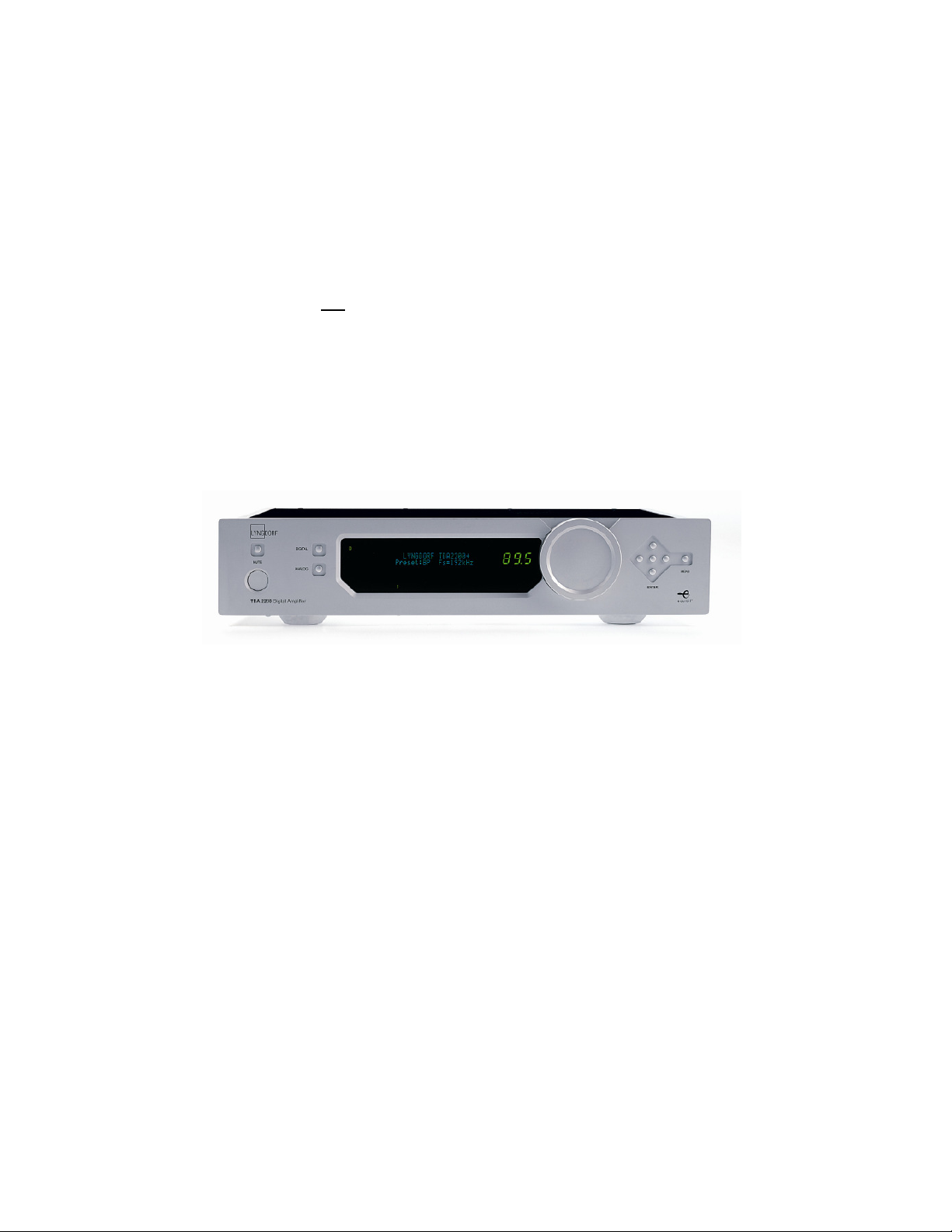
4. Introduction
Congratulations on your investment in the Lyngdorf Audio TDA 2200 with RoomPerfect™
The TDA 2200 is more than just a very good high-end amplifier, one that’s exceptionally
pure and natural sounding with even the most ‘demanding’ speaker loads. It also happens
to be a completely unique Digital Control Centre.
In fact we believe it to be the most versatile amplifier on the market today, a true state-ofthe-art device that sets new standards for what’s sonically possible to achieve in a real life
environment.
9
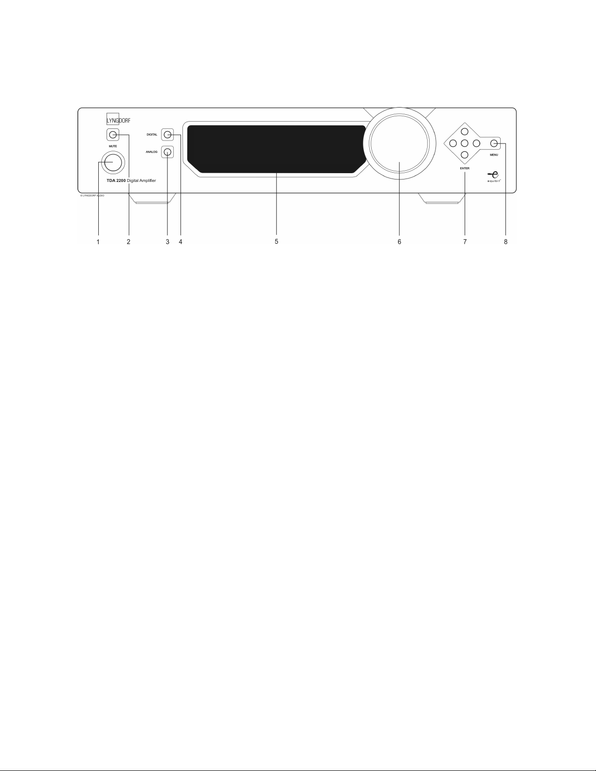
5. Front Panel
Fig 1: TDA 2200 front panel.
a. Controls
The buttons/controls on the front panel of the TDA 2200 can all be operated either with
direct presses or by operating the corresponding keys on the supplied remote control. All
the keys on the front panel [except the Mains switch (1)] are duplicated on the remote
control as well.
Mains switch (1)
Powers the TDA 2200 on/off.
Stand-by mode is selected by pressing the mute button (2) for 3 seconds or with the standby button on the remote control.
Mute (2)
Toggles Mute mode on/off. The Volume level indicator will change to “---“ when the outputs
are muted. If the volume control is changed while muted the present volume control setting
will be shown before reverting to “---”, but the outputs remain muted.
Pressing the Mute button for 3 seconds will set the TDA 2200 in stand-by mode.
Analog Input selector (3)
Changes to Analog input, or if already selected, cycles to the next Analog input.
Digital Input selector (4)
Changes to Digital input, or if already selected, cycles to the next Digital input.
Display (5)
Display with all information on menu system, status, active input selection and volume
control.
Volume wheel (6)
Optical encoded volume control wheel
Navigation keys (7)
Keys for operating the menu system: Up/Down, Left/Right & Enter
Menu button (8)
Toggles Menu mode on/off
10

b. Display Indicators
POWER
Power on is indicated with display showing all information on status and volume control,
Standby mode is indicated with the decimal dot from the volume control being lit only.
MENU
The Alphanumeric Display (2*20 Characters) is used for navigating the Menu system
1-5
Illuminates the active input
A-D
Illuminates to show whether the active input is Analog or Digital
VOLUME
3 digits indicating Volume control setting from 00.0 to 99.9 – in dB’s
MUTE
Mute is indicated by the Volume control setting “---”
11
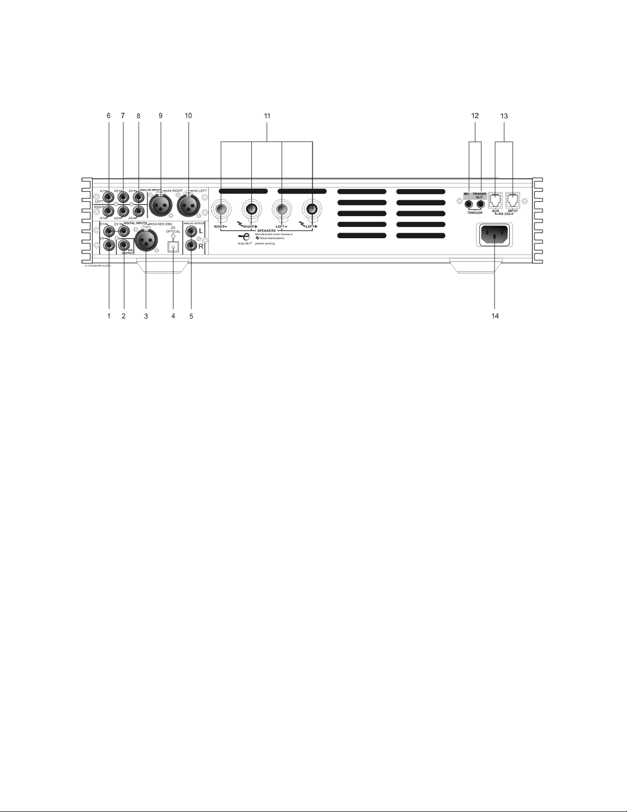
6. Rear Panel
Fig 2: TDA 2200 rear panel.
DIGITAL INPUT 1-3 (1)
RCA Connectors for SPDIF input
DIGITAL OUTPUT (2)
Selected digital input is sent – full range or filtered via the DSP - to the Digital Output
connector for daisy-chaining more than one TDA-2200. The sample rate is fixed at 96 kHz.
This output is also active when Analog input is selected.
DIGITAL INPUT 4 (3)
XLR Connector for AES input
OPTICAL DIGITAL INPUT 5 (4)
Connector for Toslink input
ANALOG OUTPUT (5)
DAC output from DSP Section
NOTE! The connectors from 6-10 are only available if the optional AD-Converter card is
mounted
INPUT (6-8)
Single-ended Analog input L/R pairs 1-3
INPUT (9-10)
Balanced Analog input L/R number 4
LOUDSPEAKER TERMINALS (11)
Loudspeaker output, NOTE! All Outputs are bridged and must never be connected to
ground because of the DC offset to Chassis
12

MIC IN(left) / TRIGGER OUT(right) (12)
DC Trigger out for remote start of SDA 2175 power amplifiers or similar equipment.
Mic. in for connection of RoomPerfect™ microphone.
RS232 INPUT/AUX (13)
RS232 communication connectors for communication with a PC, remote control from
Lyngdorf equipment with broadcast commands or linked control between amplifiers. Input
is looped to Aux out for daisy-chaining of amplifiers. The “INPUT” is used for connection to
a PC for software update, or as a control input from a Lyngdorf Master Amplifier. The
“AUX” connection is output in Master mode for controlling slave amplifiers, or bypasses
input from other master amplifiers to the next amplifier.
MAINS INPUT (14)
7. Remote Control
The remote control is used to access the menu system and replicate the buttons directly
accessible on the front panel. The buttons are as follows:The four buttons used for selecting which device to control are described below. To control
the TDA 2200 the AMP key should be pressed [please note the amplifier’s volume and
mute buttons still work when in CD mode].
• AMP – Selects the remote for operation with a Lyngdorf
Amplifier.
• RCS – No function.
• CD - Selects the remote for operation with a Lyngdorf CD
Player.
• Tuner – No function.
• Standby – The standby button toggles the TDA 2200 between
active and stand-by mode
• Digital – Changes to Digital input, or if already selected, cycles
to the next Digital input.
• Analog – Changes to Analog input, or if already selected,
cycles to the next Analog input.
• The numerical button 0 selects bypass listening mode (no
room correction filter selected)
• The numerical buttons 1-8 select focus listening mode (up to 8
different listening positions can be stored in RoomPerfect™)
• The numerical button 9 selects global listening mode.
• Info – shows the firmware version of TDA 2200
• Menu – activates or de-activates the Menu system on the
Main display
• Up / Down / Left / Right arrows – Navigation in the menu
system.
• Left / Right arrows – Toggles between voicing filters.
• Enter – Selection in menu system
• Channel -/+ - toggles down/up between inputs
• Volume Up/down – changes volume in the chosen direction
• Mute – Toggles Mute function on/off
13
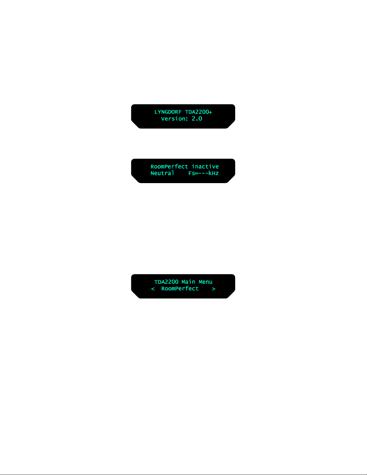
8. Menu System
The Main Display on the front panel of the TDA 2200 shows all functionality and current
status of the TDA 2200. An overview of the menu tree can be seen in the appendix.
When the amplifier is powered up the Main screen shows the current Software revision in
the Startup picture as:
After showing the initial screen, which can be used to identify the software version, the
main screen is shown.
Furthermore the Volume Control is set according to the standard settings which can be
altered in the menu system
In the display the current setting of RoomPerfect™, the voicing setting and the sample
frequency of the input are displayed. If a digital input is active the source sample rate is
detected and displayed. If the Analog option is mounted and selected the ADC sample rate
96 kHz will be displayed
Pressing the Menu button on the remote or the front panel access the top level of the
Menu system
Using the Left/right keys the Menu system settings can now be scrolled through. To
access a sub menu setting just scroll to it press the Enter button. The Sub menus
accessible in version 2.1 are:-
• RoomPerfect™
• Voicing
• Cross-over
• Delay
• ADC Level (Optional)
• Communication
• Trigger Set-up
• Remote Control
• Display
• Volume
• Advanced Set-up
The above options are described in detail as follows.
14
 Loading...