

Lyngdorf Audio SDAI 2175 User Manual
SDAI 2175
Semi Digital Integrated Amplifier
Owners Manual
- 1 -

Table of Contents
WARNINGS.........................................................................................................................................3
Explanation of graphical symbols .....................................................................................................3
Exclamation symbol.....................................................................................................................3
Lightning symbol.........................................................................................................................3
Important safety instructions.............................................................................................................4
Unpacking the SDAI 2175 ....................................................................................................................4
Accessories ......................................................................................................................................5
Operating voltage .............................................................................................................................5
Product Registration..............................................................................................................................5
Introduction ..........................................................................................................................................6
Front panel............................................................................................................................................7
Controls............................................................................................................................................7
Indicators .........................................................................................................................................8
Rear panel.............................................................................................................................................9
Menu system.......................................................................................................................................10
Software .............................................................................................................................................12
Connectors..........................................................................................................................................13
Mains Connector ............................................................................................................................13
Loudspeaker connectors .................................................................................................................14
Input connectors .............................................................................................................................14
Balanced inputs..........................................................................................................................14
Unbalanced inputs......................................................................................................................14
Trigger connectors..........................................................................................................................14
Cleaning and maintenance...................................................................................................................15
Technical specifications ......................................................................................................................15
Audio .............................................................................................................................................15
Protection .......................................................................................................................................16
Mains .............................................................................................................................................16
Trigger ...........................................................................................................................................16
Mechanical.....................................................................................................................................16
Technical assistance............................................................................................................................17
Support ...............................................................................................................................................17
- 2 -
WARNINGS
CAUTION
CAUTION: TO REDUCE THE RISK OF ELECTRICAL SHOCK,
DO NOT REMOVE COVER. NO USER-SERVICEABLE PARTS
INSIDE. REFER SERVICING TO QUALIFIED PERSONNEL.
TO REDUCE RISK OF FIRE OR ELECTRIC SHOCK, DO NOT EXPOSE THIS APPLIANCE TO RAIN OR MOISTURE.
RISK OF ELECTRICAL
SHOCK. DO NOT OPEN
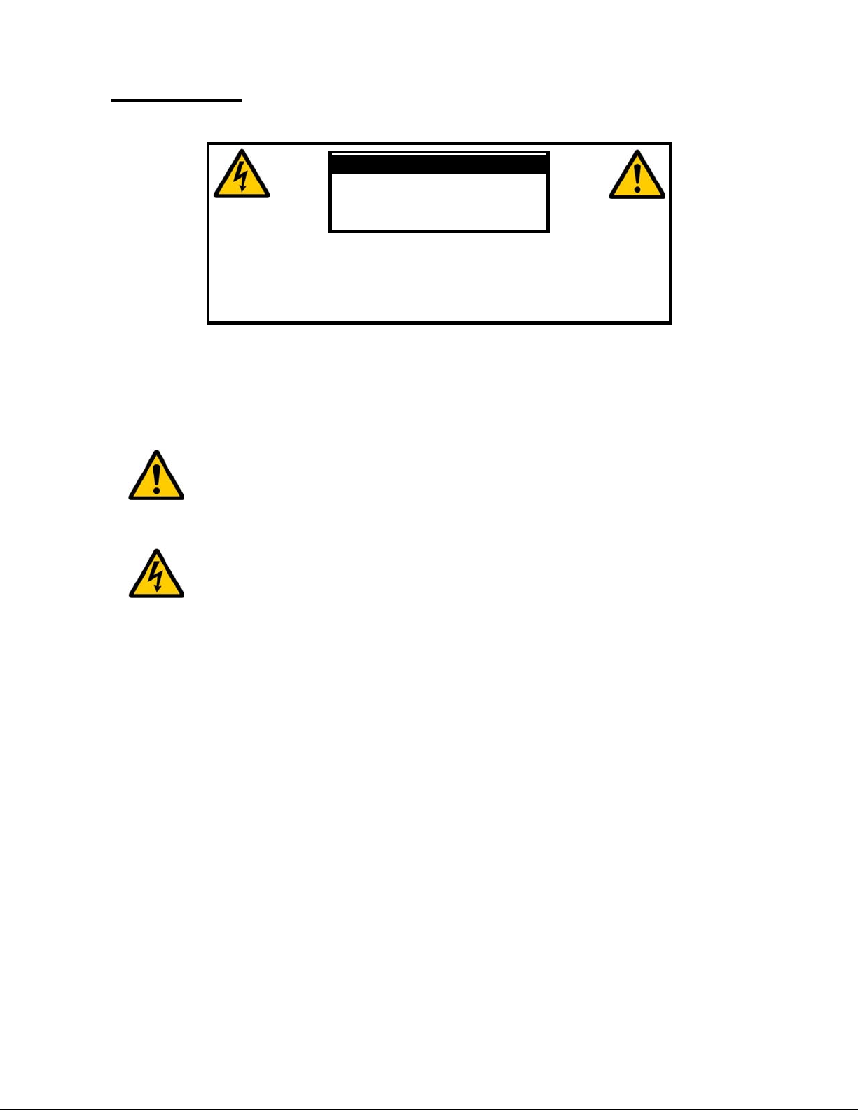
Explanation of graphical symbols
Exclamation symbol
The exclamation point within an equilateral triangle is intended to alert the user
to the presence of important operating and maintenance (servicing) instructions
in the literature accompanying the product.
Lightning symbol
The lightning with arrowhead symbol within an equilateral triangle is intended to
alert the user to the presence of uninsulated “Dangerous Voltage” within the
products’ enclosure that may be of sufficient magnitude to constitute a risk of
electrical shock to a person.
- 3 -

Important safety instructions
1:
2:
3:
4:
5:
6:
7:
8:
9:
10:
11:
12:
Use only with cart, stand, bracket, or table specified by the manufacturer, or sold with the
13:
14:
15:
15:
17:
Read these instructions carefully before installing or operating this apparatus.
Keep these instructions.
Heed all warnings.
Follow all instructions.
Do not use this apparatus near water.
Clean only with a dry cloth.
Do not block any ventilation openings. Install in accordance with the manufacturer’s
instructions.
Do not install near any heat sources such as radiators, heat registers, stoves, or other
apparatus that produce heat.
Do not defeat the safety purpose of the grounding-type plug. A grounding-type plug has
two pins and a third grounding prong. The third prong is provided for your safety. If the
provided plug does not fit into your outlet, consult an electrician for replacement of the
obsolete outlet.
Protect the power cord from being walked on or pinched, particularly at plugs,
convenience receptacles, and the point where they exit from the apparatus. Do not use
this unit with a damaged cord or plug.
Only use attachments and accessories specified by the manufacturer.
apparatus. When a cart is used, use caution when moving the cart/apparatus
combination to avoid injury from tipping-over.
Unplug this apparatus during lightning storms or when unused for long periods of time.
Connect only to the proper mains voltage.
Do not connect any output from the amplifier to any other amplifier's output or any other
voltage source.
To avoid electrical shock, make sure that no conductive part of the loudspeaker wiring is
exposed while the amplifier is operating. Do not connect loudspeakers with uninsulated
terminals to the amplifier.
Refer all servicing to qualified service personnel. Servicing is required when the
apparatus has been damaged in any way, such as when the power-supply cord or plug
are damaged, liquid has been spilled or objects have fallen into the apparatus, the
apparatus has been exposed to rain or moisture, does not operate normally or has been
dropped.
Unpacking the SDAI 2175
Carefully remove the unit and accessory kit from the carton, visually check for shipping
damage. Contact both the shipper and Lyngdorf Audio immediately if the unit bears any
sign of damage from mishandling. All Lyngdorf Audio equipment is carefully inspected
before leaving our factory.
KEEP SHIPPING CARTON AND PACKING MATERIALS for future use or in the
unlikely event that the unit needs servicing. If this unit is shipped without the
original packing, damage could occur and void the warranty.
- 4 -

Accessories
1:
2:
3:
label. The warranty will not cover any damage caused by connecting to the
You should find the following in the accessory kit:
One mains cord.
This manual.
Customer registration form.
Operating voltage
The SDAI 2175 is available in a version for 115V mains voltage and in a version for 230V
mains voltage.
Check the label on the SDAI 2175 rear panel and verify you have the version with the
proper voltage for your area.
The 115V version requires a mains voltage of 100V-120V at 50-60Hz with a current rating
of 8A.
The 230V version requires a mains voltage of 200V-240V at 50-60Hz with a current rating
of 4A.
The mains voltage setting for your SDAI 2175 can be changed ONLY BY A QUALIFIED
ENGINEER.
WARNING: Connect the power input only to the AC source printed on the
wrong type of AC mains.
Product Registration
Please record the serial number of your amplifier here for future reference. The serial
number is printed on the label on the SDAI 2175 rear panel. You will need this serial
number, should you ever require service for your SDAI 2175 power amplifier.
SDAI 2175 serial number: _____________________
Please fill in the enclosed Customer registration form and submit it to Lyngdorf
Audio so we can register you as owner of the unit and keep you informed on
future upgrades of the product.
- 5 -

Introduction
Lyngdorf SDAI 2175 is a compact, high-performance analog integrated switch-mode
amplifier utilizing some of the circuit topologies originally developed for the Lyngdorf
Millennium and M2150 amplifiers. Due to the switch-mode topology, with an efficiency of
up to 85%, the SDAI 2175 will provide its output power with minimal heat dissipation. A
massive power supply with a 650VA toroid transformer and more than 40000uF capacitors
ensures that the SDAI 2175 can deliver the current to drive even the most demanding
loudspeakers.
The SDAI 2175 has 2 gold-plated XLR connectors accepting balanced input signals and 6
stereo inputs with 2 gold-plated RCA connectors for unbalanced signals. The SDAI 2175
has a stereo tape out of the selected line level input signal and pre out of the selected
input signal after the volume control as either balanced signal from the gold-plated XLR
connectors or unbalanced from the gold-plated RCA connectors.
The volume control is implemented as a high precision digital controlled analog attenuation
in 0.1 dB steps over a 100 dB range. Input selection is performed via precision relays with
double gold plated construction of the contact set. These kind of relays are normally only
used in expensive measurement equipment for high linearity and low losses.
All controls can be operated from the front panel via the logical user interface or by use of
the remote control. Or as an option the setup can be performed via a PC interface and the
Lyngdorf SDAI2175 can be controlled from other Lyngdorf products capable of
broadcasting control codes.
The input signal is fed to the volume control circuit via an AC coupled true instrumentation
type input amplifier. Except for this AC coupling, the SDAI 2175 is fully DC coupled with no
bypass capacitors or DC servos to degrade the performance. The protection circuitry in the
SDAI 2175 shuts down the unit in case of over-temperature, DC voltage on the outputs
and too high output current. The amplifier will resume normal operation when the fault
condition is no longer present.
A trigger output on a 3.5mm jack connector allows the SDAI 2175 to control one or more
SDA2175’s power condition.
- 6 -
 Loading...