

LY International Electronics H-8700 Owner's Manual

OWNER'S MANUAL
INFRARED WIRELESS CONFERENCE
SYSTEM
Version: REV1.0 (2016)

1
[Table of Contents]
Overview
1. System configuration and description-----------------------------------------------3
1.1 System features-----------------------------------------------------------------------3
1.2 Infrared conference system main unit ----------------------------------------------3
1.2.1 Picture of the actual object -----------------------------------------------------------3
1.2.2 Features of infrared conference system main unit -----------------------------------3
1.2.3 Schematic diagram of infrared conference system main unit -----------------------4
1.2.4 Parameter of infrared conference system main unit----------------------------------5
1.3 Infrared conference system microphone unit ---------------------------------------5
1.3.1 Picture of the actual object -----------------------------------------------------------5
1.3.2 Features of infrared delegate microphone -------------------------------------------5
1.3.3 Features of infrared chairman microphone ------------------------------------------6
1.3.4 Schematic diagram of infrared microphone ------------------------------------------6
1.3.5 Parameter of infrared microphone unit -----------------------------------------------7
1.4 Distributor-----------------------------------------------------------------------------7
1.4.1 Picture of the actual object -----------------------------------------------------------7
1.4.2 Features of distributor ----------------------------------------------------------------7
1.4.3 Schematic diagram of distributor ----------------------------------------------------8
1.4.4 Parameter of distributor --------------------------------------------------------------8
1.5 Infrared transceiver unit -------------------------------------------------------------8
1.5.1 Picture of the actual object------------------------------------------------------------8
1.5.2 Features of transceiver unit-----------------------------------------------------------9
1.5.3 Schematic diagram of transceiver unit-----------------------------------------------9
1.5.4 Parameter of transceiver unit---------------------------------------------------------9
1.6 Battery charger ---------------------------------------------------------------------10
1.6.1 Picture of the actual object----------------------------------------------------------10
1.6.2 Features of battery charger----------------------------------------------------------10
1.6.3 Schematic diagram of battery charger----------------------------------------------10
1.6.4 Parameter of battery charger--------------------------------------------------------11
1.7 Infrared conference system LIP battery --------------------------------------------11
1.7.1 Picture of the actual object----------------------------------------------------------11
1.7.2 Features of LIP battery---------------------------------------------------------------11
1.7.3 Schematic diagram of LIP battery---------------------------------------------------11
1.7.4 Parameter of LIP battery-------------------------------------------------------------11
1.8 AC power adapter -------------------------------------------------------------------12
1.8.1 Picture of the actual object----------------------------------------------------------12
1.8.2 Schematic diagram of AC power adapter--------------------------------------------12
1.8.3 Parameter of AC power adapter-----------------------------------------------------12
2. System installation and setting-----------------------------------------------------13
2.1 System connection diagram---------------------------------------------------------13
2.2 Warning------------------------------------------------------------------------------14
2.2.1 CAUTION on handling of the microphone unit---------------------------------------14
2.2.2 CAUTION on installation-------------------------------------------------------------15
2.2.3 CAUTION on battery charger handling----------------------------------------------15
2.2.4 CAUTION on battery handing--------------------------------------------------------15

2
2.2.5 CAUTION on handling the AC adapter-----------------------------------------------15
2.3 Identify room layout-----------------------------------------------------------------16
2.3.1 Check coverage area-----------------------------------------------------------------16
2.3.2 The relationship between ceiling height and infrared emitting and receiving
coverage area------------------------------------------------------------------------16
2.3.3 Check quantity of transceiver unit---------------------------------------------------16
2.3.4 System configuration----------------------------------------------------------------17
2.4 Installation and connection of IR main unit-----------------------------------------17
2.4.1 IR main unit installation-------------------------------------------------------------17
2.4.2 IR main unit to IR transceiver unit---------------------------------------------------17
2.4.3 IR main unit to sound system--------------------------------------------------------18
2.4.4 IR main unit to video processor------------------------------------------------------18
2.5 Installation of IR transceiver unit---------------------------------------------------19
2.5.1 IR transceiver operating range------------------------------------------------------19
2.5.2 Installation diagram of IR transceiver unit------------------------------------------20
2.5.3 Wiring between IR transceiver unit and main unit when using distributors--------20
2.5.4 Caution item-------------------------------------------------------------------------21
2.6 Installation of IR microphone unit---------------------------------------------------22
2.6.1 Mounting and dismounting the battery----------------------------------------------22
2.6.2 Mounting and dismounting the microphone-----------------------------------------22
2.6.3 Examples of square arrangements--------------------------------------------------23
2.7 System setting-----------------------------------------------------------------------23
2.7.1 Main unit setting---------------------------------------------------------------------23
2.7.2 Microphone setting------------------------------------------------------------------28
2.7.3 Video camera tracking function-----------------------------------------------------29
3. How to use this system---------------------------------------------------------------29
3.1 How to use the main unit------------------------------------------------------------29
3.1.1 Powered on/off the main unit--------------------------------------------------------29
3.1.2 Main unit LCD display-----------------------------------------------------------------29
3.1.3 Panel indicator------------------------------------------------------------------------29
3.1.4 Warning-------------------------------------------------------------------------------30
3.2 How to use the microphone----------------------------------------------------------30
3.2.1 Powered on/off the microphone-----------------------------------------------------30
3.2.2 Microphone OLED display------------------------------------------------------------30
3.2.3 Turn on/off the microphone----------------------------------------------------------31
3.3 Charge the battery by DC power adapter-------------------------------------------32
3.4 Charge the battery by charge box---------------------------------------------------32
4. Troubleshooting---------------------------------------------------------------------34
3
Overview
The infrared conference system has all the advantages of infrared communication
complete with wireless transceiver microphone units. Wireless infrared technology
provides the user with greater flexible whilst configuring the system and freedom of
choice when placing microphones, it guarantees conference privacy and protects the
system from wiretapping and radio interference. It’s the best wireless conference
solutions for small-scale conferences.
1. System Configuration and description
Infrared conference system main unit, infrared transceiver unit, infrared chairman
microphone, infrared delegate microphone, distributor, battery charger, etc.
1.1 System features
a.
Infra-red transmission technology guarantees privacy.
b.
Perfect sound quality as CD from the microphone.
c.
IR communication system eliminates the need of connecting the conference units.
Installation can be done quick and smart without cumbersome arrangements.
d.
Fully functions (Discuss & Video tracing), support FIFO (1/2/3), Limit (1/2/3) and
chairman only mode, microphones in one system up to 127 units.
e.
Microphones can be operated on either their built-in rechargeable lithium-ion
batteries or AC power supply. Battery life approx. 6 hours during speech and approx.
30 hours when standby.
f.
Microphone LCD can display system and conference information.
g.
Excellent immunity to RF interference from mobile phones and RF devices.
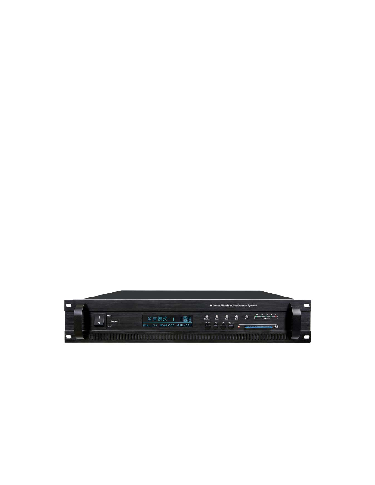
1.2 Infrared conference system main unit
1.2.1 Picture of the actual object
1.2.2 Features of infrared conference system main unit
a. Support Mode: Limit (1/2/3), FIFO (1/2/3), Chairman Only
b. Support video camera auto-track with video processor
c. 160x32 dot matrix LCD display system information
d. Two group audio output interface to support external audio system
e. Installation: 19-inch frame
f. Designed accordance to UL and CE standards
g. If main unit turn off power, microphone will shut off t he power within 60 seconds.
4
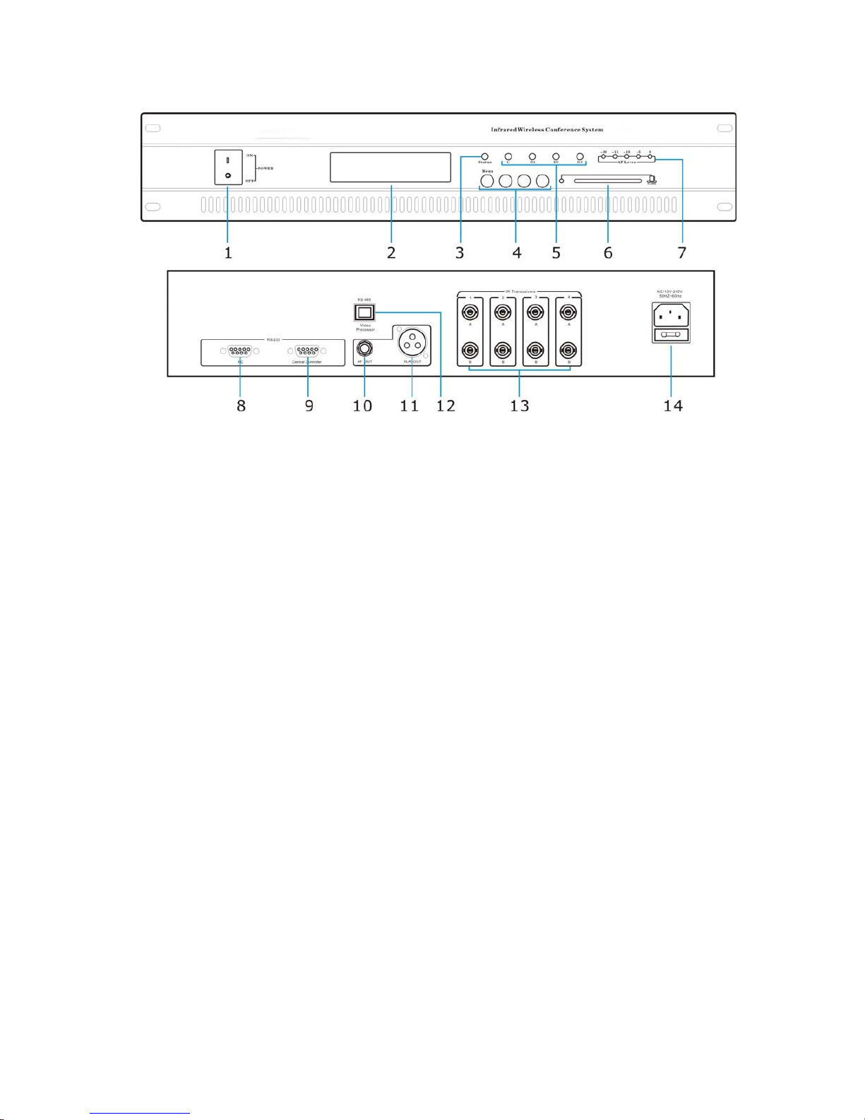
1.2.3 Schematic diagram of Infrared conference system main unit
1) Power switch (Press I to turn on the power, power indicator is lighting, press O to turn
off the power)
2) LCD (Display current mode, online microphone number, activity microphone number
and ID, etc)
3) LED indicator: Data communication indicator, if main unit data communication
properly, the blue LED will flashing rhythmically.
4) System menu and function key
5) Audio channel indicator (first channel for chairman mic, others for delegate)
6) Admin card interface
7) Audio Level indicator
8) RS232 data control interface---to PC
9) RS232 data control interface---to central control system
10) Audio out interface
11) XLR audio output interface
12) RS485: External video processor connection interface
13) IR transceiver connection interface A/B (1-4)
14) AC110V 50Hz-60Hz / AC220V 50Hz-60Hz
5
1.2.4 Parameter of infrared conference system main unit
Items Parameter
Transmission method Wireless infrared
Channels 4 audio+ 1 data
Carrier frequency band 4MHz-8MHz
Modulation method FM/FSK
Receiving sensitivity -100dBM
Output level 0dBV/+6dBV
Infrared operating distance >12M
Frequency response 100Hz-12KHz
S/N Ratio >82dB
T.H .D. <0.5%
Transmission consumption 0dBM
Communication rate 100KBPS
Signal covering range Radius 100M
Power supply AC110V 50Hz-60Hz / AC220V 50Hz-60Hz
Consumption Rating 10W
Operating temperature range 0-40 degree
Dimensions 484×377×85mm
N.W 8kg
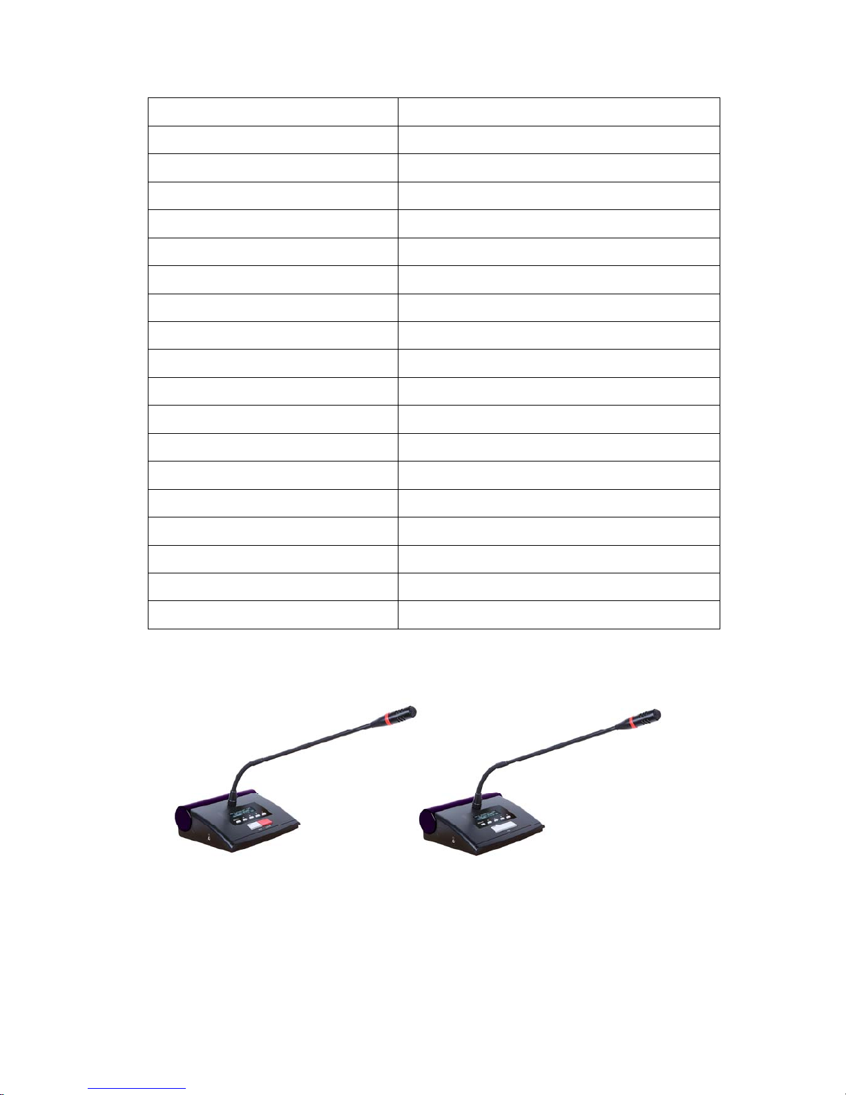
1.3 Infrared conference system microphone unit
1.3.1 Picture of the actual object
1.3.2 Features of infrared delegate microphone
a. Newly digital design
b. Portable table moving and microphone pipe can be pull out. Extended pipe optional.
c. Electric capacity type microphone, equipped with w indshield cover
d. LCD display microphone ID, signal level, battery level, microphone state, control
channel, etc.
e. Equipped with microphone on/off key and indicator.
6
f. Equipped with 5 function keys to support microphone id/LCD contrast/Language
setting and service calling function.
g. Microphone will shut off the power in 60 seconds to save battery power if system
communication is error.
h. LCD will display “IR Signal Weak/Error” if the IR signal is weak when microphone
working.
1.3.3 Features of infrared chairman microphone
Including the functions of the delegate unit, chairman unit has other following functions:
a. Chairman microphone can turn on any time.
b. In one system microphones just support one chairman microphone and the ID number
should be 1.
c. Priority function: chairman can turn off delegate microphones any time.
d. Chairman only mode: Delegate microphone can not be turned on again after chairman
microphone press priority button. The chairman need quit this mode first, and then
delegate microphone can be turned on again.
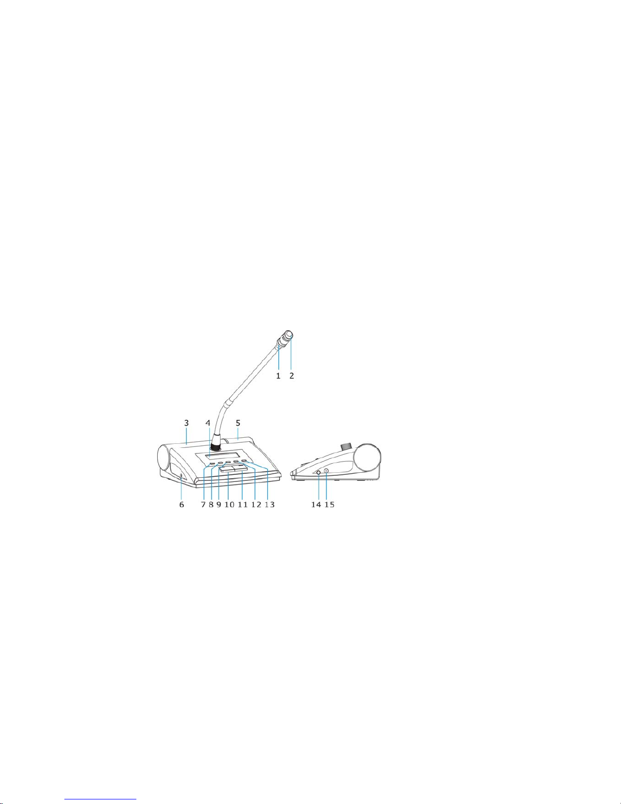
1.3.4 Schematic diagram of infrared microphone
1) Annular red indicator lamp to show the microphone state.
2) Unidirectional electret MIC
3) IR transmission sensor
4) LCD display
5) IR receiving sensor
6) Earphone monitor 3.5mm jack
7) Menu/Back key: Press this key to enter menu setting or back after setting
8) Monitor volume leave -
9) Monitor volume leave +
10) MIC ON/OFF key
11) Chairman Priority
12) Service Calling function key
13) Mute function key
14) Microphone power switch
15) DC power input
7
1.3.5 Parameter of infrared conference system microphone unit
Items Parameter
Transmission method Wireless infrared
Channels 4 audio+ 1 data
Carrier frequency band 4MHz-8MHz
Modulation method FM/FSK
Infrared radiator consumption +10dBM
Receiving sensitivity -100dBM
Mic sensitivity -44dB±2dB
Frequency response 100Hz-12KHz
S/N Ratio >82dB
T.H .D. <0.5%
Reference speaking distance 10~30cm
Consumption Rating 8W
Operating temperature range 0-40 degree
Dimensions 168×145×60mm
Length of gooseneck 400mm (optional)
N.W 1.2kg (with battery)
Battery LIP battery12V/4000MAH
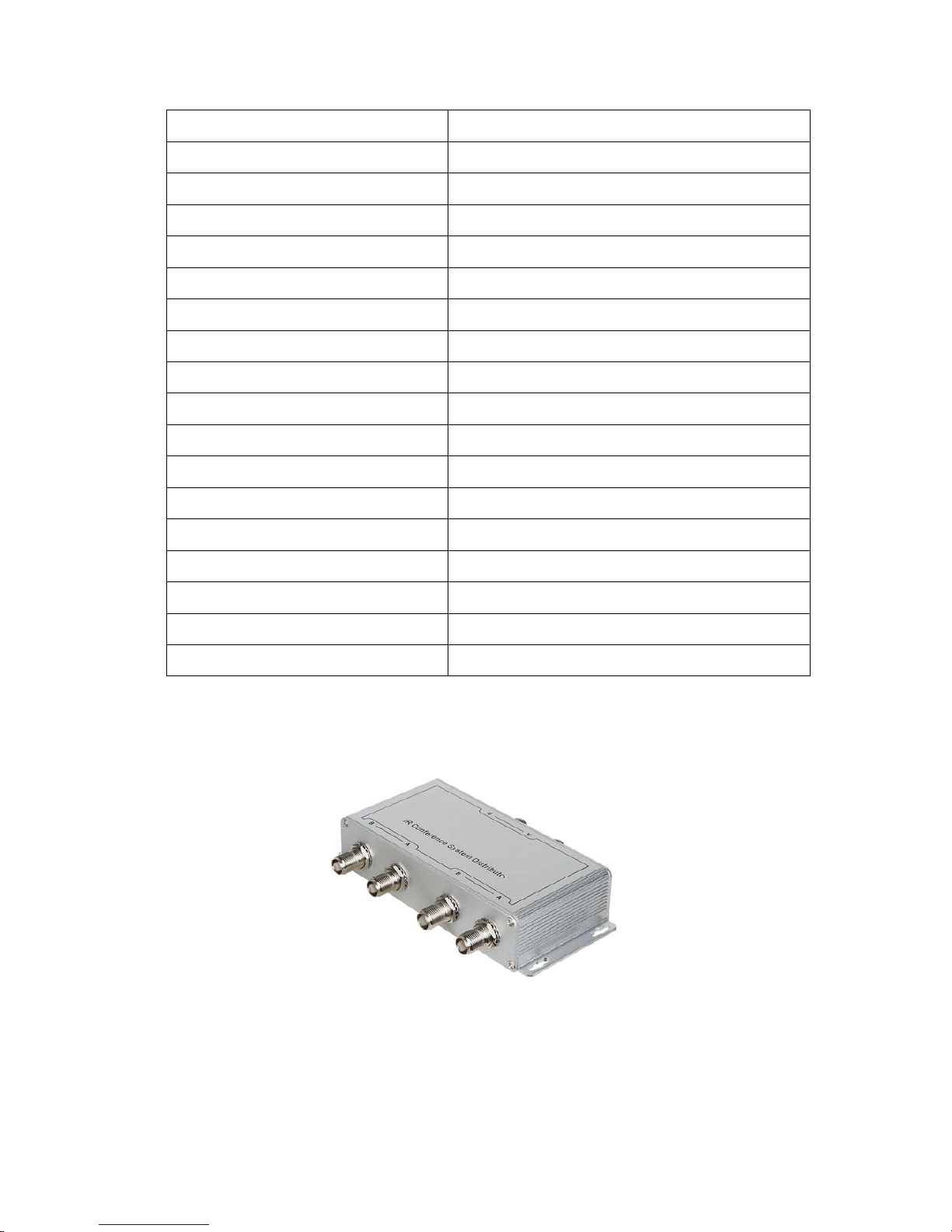
1.4 Distributor
1.4.1 Picture of the actual object
1.4.2 Features of distributor
a. Adopt impedance balancing branch connector (2 group input, 1 group output)
b. Low insertion loss computation
c. Perfect plating surface treatment with excellent shielded function
8
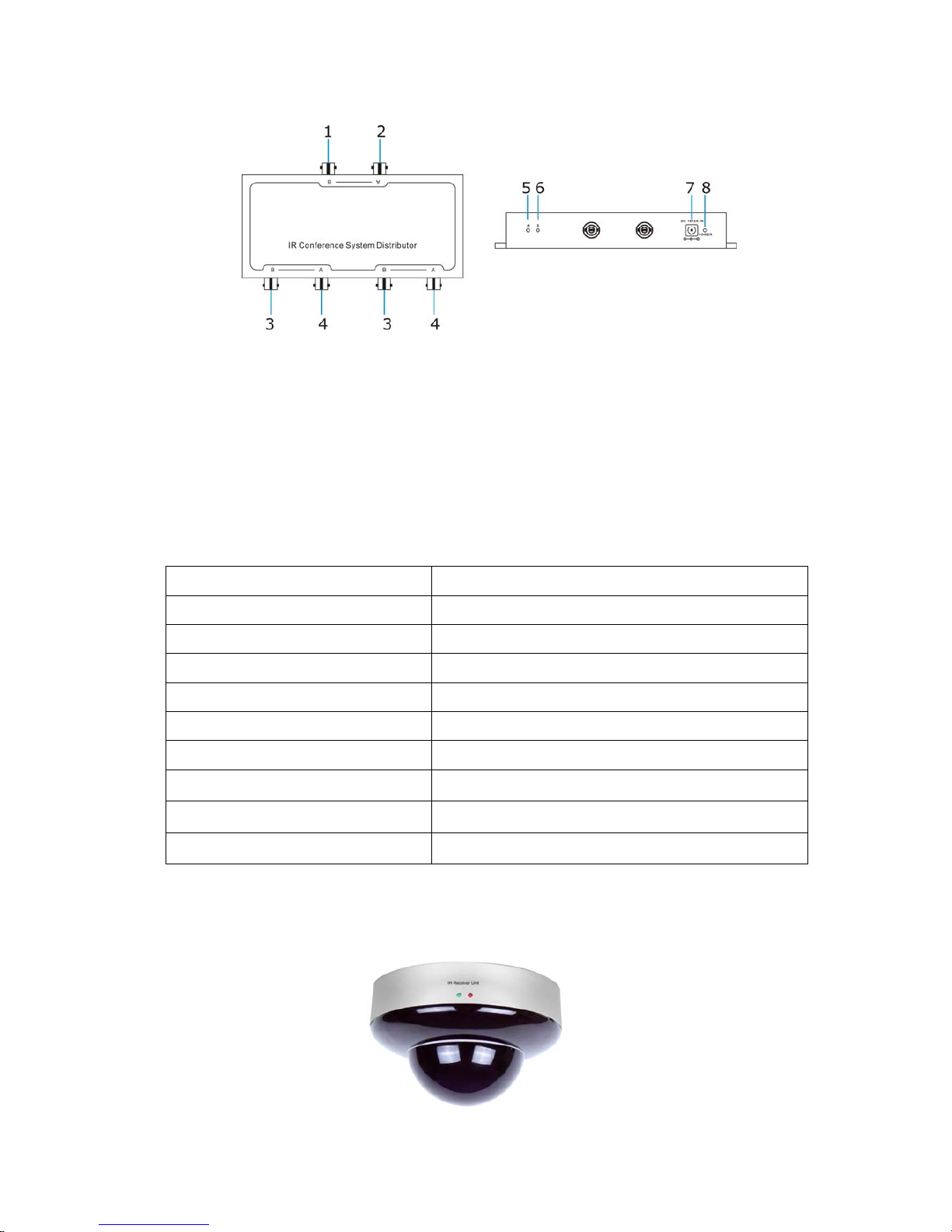
1.4.3 Schematic diagram of distributor
1) IR signal TNC terminal B: IN
2) IR signal TNC terminal A: IN
3) IR signal TNC terminal B: OUT
4) IR signal TNC terminal A: OUT
5) LED indicator for group A cable: Red
6) LED indicator for group B cable: Green
7) DC power jack
8) Power indicator LED
1.4.4 Parameter of distributor
Items Parameter
Carrier frequency band 4MHz-8MHz
Insertion loss computation
<1dBM
Input/Output Impedance 50Ω
Input terminal 2
Output terminal 4
Term i nal type TN C
Dimensions 80×65×20mm
Power Supply DC12V/2A
N.W 670g
1.5 Infrared transceiver unit
1.5.1 Picture of the actual object
9
1.5.2 Features of transceiver unit
a. Adopt mounting hook installation, easy to install.
b. Wide-angle, transceiving range is approximately 150 degrees.
c. Signal gain more than 35dBM
d. Adopt low consumption electro circuit
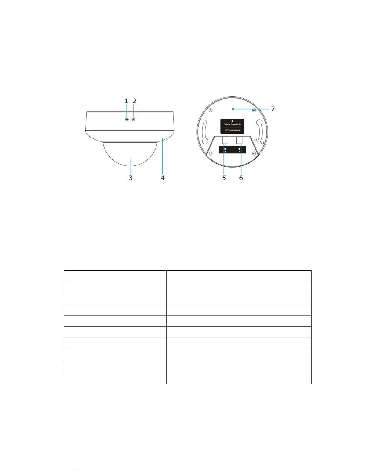
1.5.3 Schematic diagram of transceiver unit
1) LED indicator for group A cable: Red
2) LED indicator for group B cable: Green
3) IR signal receiving sensor
4) IR signal transmission sensor
5) IR signal output TNC terminal B
6) IR signal input TNC terminal A
7) Safety rope hole
1.5.4 Parameter of infrared conference system transceiver unit
Items Parameter
Carrier frequency band 4MHz-8MHz
Power supply DC24V from Main unit
Rated current 380mA
Receiving sensitivity -100dBM
Gain 40dBM
Input/Output Impedance 50Ω
Term i nal type TN C
Dimensions Φ145×100mm
N.W 1.71kg
10
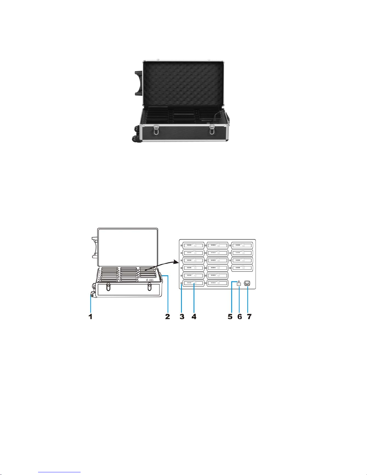
1.6 Battery charger
1.6.1 Picture of the actual object
1.6.2 Features of battery charger
a. Input Voltage: AC 110V~220V
b. Charges 10 PCS of LIP battery per charging
c. Intelligent charging management electro circuit to protect the LIP battery
d. Equipped with extendible handle and pulley, easy for moving.
1.6.3 Schematic diagram of battery charger
1) Pulley
2) Extendible handle
3) Charging status indicator LED
4) Battery holder
5) Power indicator
6) Power on/off switch
7) AC adapter jack (AC110V-220V~ 50Hz-60Hz)
 Loading...