

Page 1
CONFERENCE VIDEO PROCESSOR
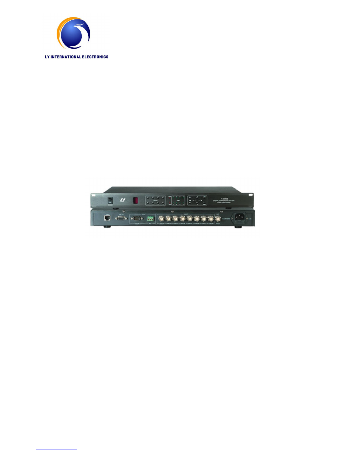
H-8008
INSTRUCTION MANUAL
Page 2
Video Camera Auto-Track Conference System
In modern society, the request of conference is not just limited on the simple sound, but
also requests the music, video backup records or remote transmission, this system is designed
for meeting this kind of requests. This system can implements connection between the
speaking and photography to implement the automatic tracking location photography function.
This system easy to operate, setting the photography spot through using the software, and it
can also setting the spot without the computer, so that to enhance the flexibility for using and
save the cost.
Function of Video Processor (H-8008)
1. Build-in video switching matrixes (8 input, 2 output).
2. 256 video camera auto-track control points. Multi-machine cascade
3. Support Pelco-D and VISCA protocol. (Pelco-D, Baud Rate: 9600, VISCA , Baud Rate:9600)
4. The processor can communicate with the equipments by RS232 interface, such computer or
video switching matrixes.
5. High speed dome follows the location for last opening of all speaking representative , when
the microphone which opened last was closed, the dome will follows back the last following
camera spot, and when all the speaking representative microphone were closed, the dome
will automatically moves back to the standby position.
6. When without the computer, set the camera spot advanced through pressing the button in
main unit board, and also set by the IR remote controller.
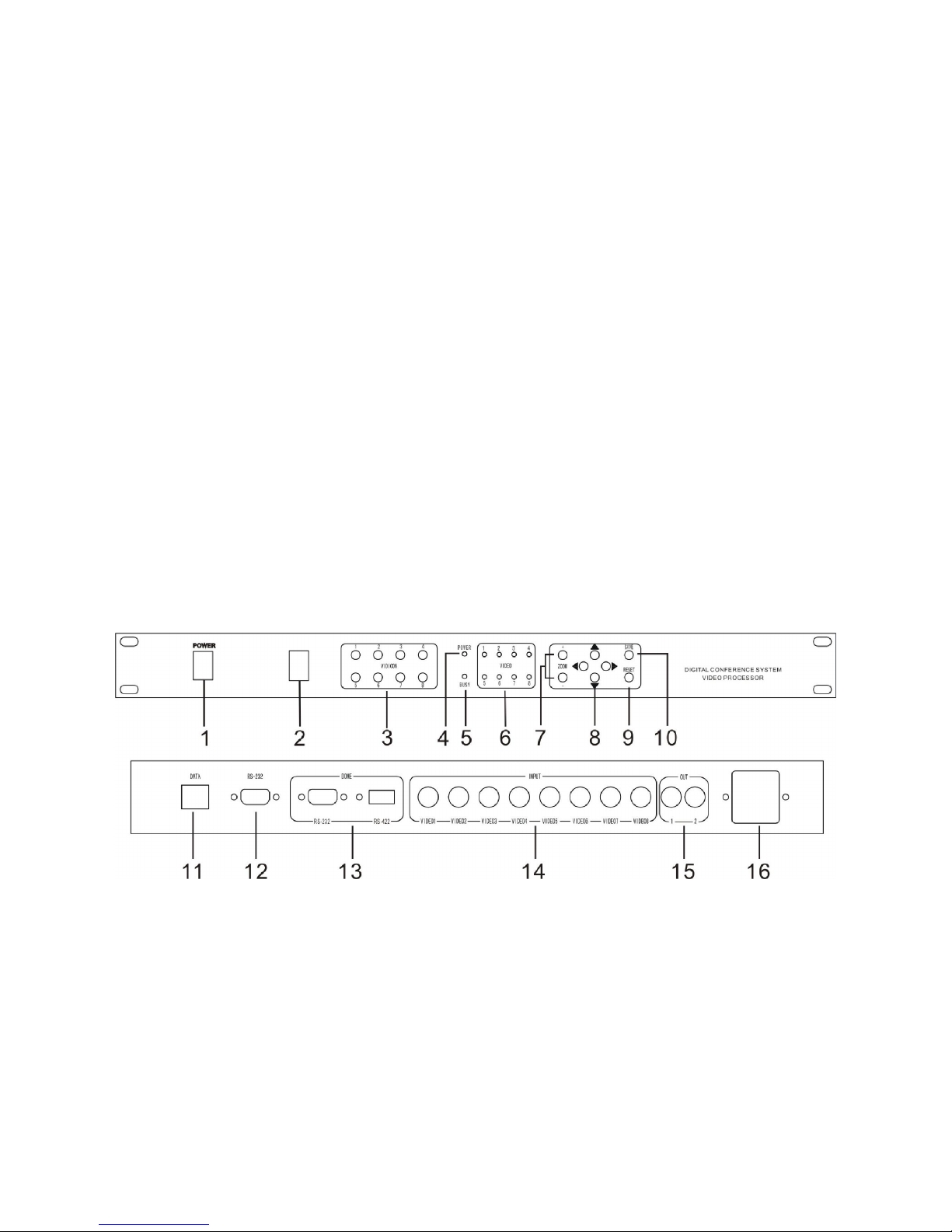
H-8008 Schematic diagram:
1. Power switch
2. IR Lens
3. Camera number selecting button (VIDICON 1-8), send the photography to the related
display screen through pressing this button
4. Power indicative lamp
5. Busy indicative lamp
6. Power indicator of each camera
7. Zoom setting
8. Camera direction set button (up, down, left, right)
9. Reset button (delete all the pre-setting spot)
Page 3

10. Save button (save the pre-setting spot)
11. Data port (connect the conference main unit)
12. RS232 port (connect the computer)
13. High speed dome control port, RS485/RS232 (connect to the high speed dome data control
line)
14. High speed dome video input port (connect the high speed dome video signal)
15. Video port (connect the monitor)
16. Power supply (AC220V)
High speed dome characteristics:
18 times auto-focus len, focusing distance: 4.1~73.8 mm.
The horizontal direction can be 360 degrees unrestricted rotation, running speed can be up to
254 degrees / sec, vertical direction speed can be moved 95 degrees, running speed can be up
to 80 degrees / sec.
64 preset spots, can be set with programs and save, and call the preset spot freely for
Checking
63 high speed domes can be connected
Full-features automatic or manual control. aperture white balance, gain compensation with
reversible light and automatic gained. Both automatic and manual control is work.
Camera components: 1/4 Inch interline transfer CCD
Action pixels: 380,000 768(H)X 494 (V)
Resolution: 480 TVL
Please refer details operation in the camera using manual
Remote control using instruction:
The remote control used in setting automatic location for following camera preset spot, open
and install AAA battery when using, and take it out if don’t used for long time. Make sure the
central processor in the working state when setting, it is better to point the remote control to
the IR Lens in the central processor; Remote control transmitting distance is about 15M. Turn
on the related microphone in manual operation when setting (in FIFO mode), after debug the
required image by saving button and then to the next point of a preset settings
1. Remote control on/off button
2. Protocol setting ( original Pelco-D)
3. Baud rate setting (original 9600)
4. High speed dome choosing button(1-8)
5. Focus near
6. Focus far
7. Camera dome direction adjustment button: up, down,
left, right
8. Zoom +
9. Zoom –
10. Camera speed setting +
11. Camera speed setting –
12. Save, press this button for one second after set the
preset, then it will save the data
Page 4

13. Reset, press this button for about 2 second, then it will delete all the camera preset, please
use it carefully.
14. Video-home, the video image will back to the video-home position when all mic off.
Connecting and operation instruction for camera central processor
1. Connect the data port in conference main unit to the data port in this unit with data cable
2. Connect the RS-232 port to the computer with computer cable
3. Install the software to the computer(optional)
4. Connect the high speed dome date cable to the dome port in this unit (if has many unit for
using, please use the multiple connecting), connect the high speed dome video cable
(within 8 sets) in to each input in the board behind the central processor (V1, V2, V3, V4,
V5, V6, V7, V8), the camera ID should be same as the video in port, it must configure
another distributor machine if over 8 sets, the high speed dome connect to the video
distributor
5. After confirmed the conference system is adjusted to normal, open the conference system
and this main unit, computer software; camera function setting and testing according to the
software instruction.
Port Schematic diagram
Name RJ45 DB9
Female
DB9
Male
RS485/RS422
BNC Power Data
Pic
Description
1.GND
2.GND
3.RS485A
+
4.RS485B-
5.NC
6.NC
7.GND
8.GND
1.NC
2.TXD
3.RXD
4.NC
5.GND
6.NC
7.NC
8.NC
9.NC
1.NC
2.RXD
3.TXD
4.NC
5.GND
6.NC
7.NC
8.NC
9.NC
1.RS485 A+
(TXD +)
2. RS485 B-
(TXD -)
3. RXD +
4. RXD –
5. GND
1.GND
2.VIDEO
1.POWER
2.GND
3.POWER
4.FUSE
1.RS485B-
2.RS485A+
3.AC24V
4.AC24V
Port name DATA RS232 DOME
(VISCA)
DOME
(PELCO-D)
INPUT/
OUTPUT
220V
POWER
DOME
DATA PORT
Page 5

Page 6

System connection:
 Loading...