

Page 1
OWNER'S MANUAL
DIGITAL CONFERENCE SYSTEM
H-7300 SERIES
Page 2

2
INDICE
1. IMPORTANT SAFETY INSTRUCTIONS..................................................................................................3
2. DESCRIPTION..........................................................................................................................................5
3. FRONT PANEL FUNCTIONS AND CONTROLS - H-7300....................................................................5
4. REAR PANEL FUNCTIONS AND CONTROLS - H-7300......................................................................6
5. PRESIDENT (H-7800c) AND DELEGATE (H-7800d) UNIT FUNCTIONS AND CONTROLS............7
6. CONNECTION..........................................................................................................................................8
7. HOW TO USE THE SYSTEM.................................................................................................................13
8. FRONT PANEL FUNCTIONS AND CONTROLS - H-08EX.................................................................15
9. REAR PANEL FUNCTIONS AND CONTROLS - H-08EX.................................................................15
10. EXPANSION UNIT CONNECTION....................................................................................................16
11. PACKAGE CONTENTS...................................................................................................................18
12. TECHNICAL FEATURES...................................................................................................................18
Page 3
3
1. IMPORTANT SAFETY INSTRUCTIONS
CAUTION:
To reduce the risk of electric shock do not remove cover (or back panel). No user serviceable parts
inside. Refer servicing to qualified personnel only.
WARNING:
To reduce the risk of fire or electric shock, do not expose this apparatus to rain or moisture.
This symbol is intended to alert the user of the presence of uninsulated dangerous voltage within the
product enclosure that may be of sufficient magnitude to constitute a risk of electric shock to persons.
This symbol is intended to alert the user of the presence of important operating and maintenance
(servicing) instruction in the literature accompanying the appliance. Please carefully read the owner’s
manual.
INSTRUCTIONS:
All safety and operating instructions should be read before the product is operated.
Retain these instructions:
All safety and operating instructions should be retained for future reference.
This owner’s manual should be considered as a part of the product, it must accompany it at all times, and it needs to be
delivered to the new user when this product is sold. In this way the new owner will be aware of all the installation,
operating and safety instructions.
Heed all warnings:
All warnings on the product and in owner’s manual should be adhered to.
Heed all warnings.
Follow all instructions:
All operating and user’s instructions must be followed.
Sentences preceded by symbol contain important safety instruction. Please read it carefully.
DETAILED SAFETY INSTRUCTIONS.
Water and moisture:
This apparatus should not be used near water (i.e. bathtub, kitchen sink, swimming pools, etc.)
Ventilation:
This apparatus should be placed in a position that doesn’t interfere with its correct ventilation. This unit, for example,
should not be placed on a bed, sofa cover o similar surfaces that could cover ventilation openings, or placed in a
built-in installation, such a bookcase or a cabinet that could block air flow trough ventilation openings.
Heat:
This apparatus should be placed away from sources of heat, like radiators, heat registers, stoves or other products
(including amplifiers) that produce heat.
Power sources:
This apparatus should only be connected to a power source of type specified in this owner’s manual or on the
unit.
If the supplied AC power cable plug is different from wall socket, please contact an electrician to change the AC
power plug.
Grounding or Polarization:
All precautions must be observed in order to avoid defeating grounding or polarization.
Unit metal parts are grounded through the AC power cord.
If the AC power outlet doesn’t have grounding, consult an electrician for outlet grounding.
Power cable protection:
The power cable should be routed in such a way that it will not be walked on or pinched by items placed upon or
against it, paying particular attention to cables at their connections, receptacles and wall outlet.
Page 4

4
Cleaning:
You can clean the exterior of the unit with compressed air or a damp cloth.
Don’t clean the unit using solvents like trichloroethylene, thinners, alcohol, or other volatile or flammable fluids.
Non use periods:
The unit AC power cable should be unplugged from the outlet if it’s unused for long periods.
Objects or liquid entry into the unit:
Be careful that no objects fall into the unit or that no liquid is spilled inside the unit through ventilation openings.
Safe power line use:
Hold the plug and the wall outlet firmly while disconnecting the unit from AC power.
When the unit will not be used for a long period of time, please unplug the power cord from AC power outlet.
To avoid power cable damage, don’t strain the AC power cable and don’t bundle it.
In order to avoid damage to the unit's power cable, be sure that the power cable is not walked on or pinched by
heavy objects.
Unit relocation:
Before relocating the unit, please control the unit is turned off. The power cord must be unplugged from the wall
outlet, and all the connecting cables should be disconnected as well.
Do not open this unit:
Do not attempt to open or repair this unit yourself. For any problem not described in this owner’s manual, please
refer to qualified personnel only or consult us or your National Distributor. Any improper operation could result in fire
or electric shock.
Damages requiring services:
Do not attempt to perform operations not described in this user’s manual.
In the following cases please refer to an authorized service center or skilled personnel:
- When the unit works improperly or it doesn’t work at all.
- If power cord or plug is damaged.
- If liquid has spilled, or objects have fallen into the unit.
- The unit has been exposed to rain.
- The unit doesn’t operate normally or exhibits a marked change in performance.
- If the product has been dropped or has been damaged in any way.
Maintenance:
The user shouldn’t attempt maintenance not described in this user’s manual. All maintenance should be performed
by qualified personnel only.
IMPORTANT SAFETY INSTRUCTIONS:
Install this unit following owner’s manual instructions.
Do not install, connect or disconnect power supply when the unit is powered, otherwise there is a high risk of
electric shock.
Do not open the unit, there are no user serviceable parts inside.
If you detect a particular smell from the unit, please immediately turn it off and disconnect the AC power cord.
Don’t block the unit's ventilation openings.
Avoid using this unit in overload for a long period.
Don’t force commands (switches, controls, etc.)
To obtain good speaker wire contact, please tighten the screw terminals firmly.
For safety reasons, do not defeat the grounding connection. Grounding is for user safety.
Use only connectors and accessories suggested by the manufacturer. .
This unit should be fitted in an equipment rack (see INSTALLATION) and kept far from:
Wet places
Direct exposure to heat sources (like sun light)
Improperly ventilated places
Disconnect the power cord during storms or when the unit is not in use.
In order to prevent fire and reduce risk of electric shock, it is necessary to keep the unit far from dripping
water. Please don’t put cups, vases or other object containing liquids over the unit. In case of interference from
source signal, THD value will raise over 10%. Don’t place this unit in a bookshelf or in other enclosed spaces.
We are not responsible for any damage that occurs due to a incorrect installation of the unit.
Page 5
5
Thank you for choosing this product and for trusting our brand, which strives to be synonymous with
professionalism, precision, high quality and reliability. All of our products comply with EC regulations
regarding audio equipment for continuous use.
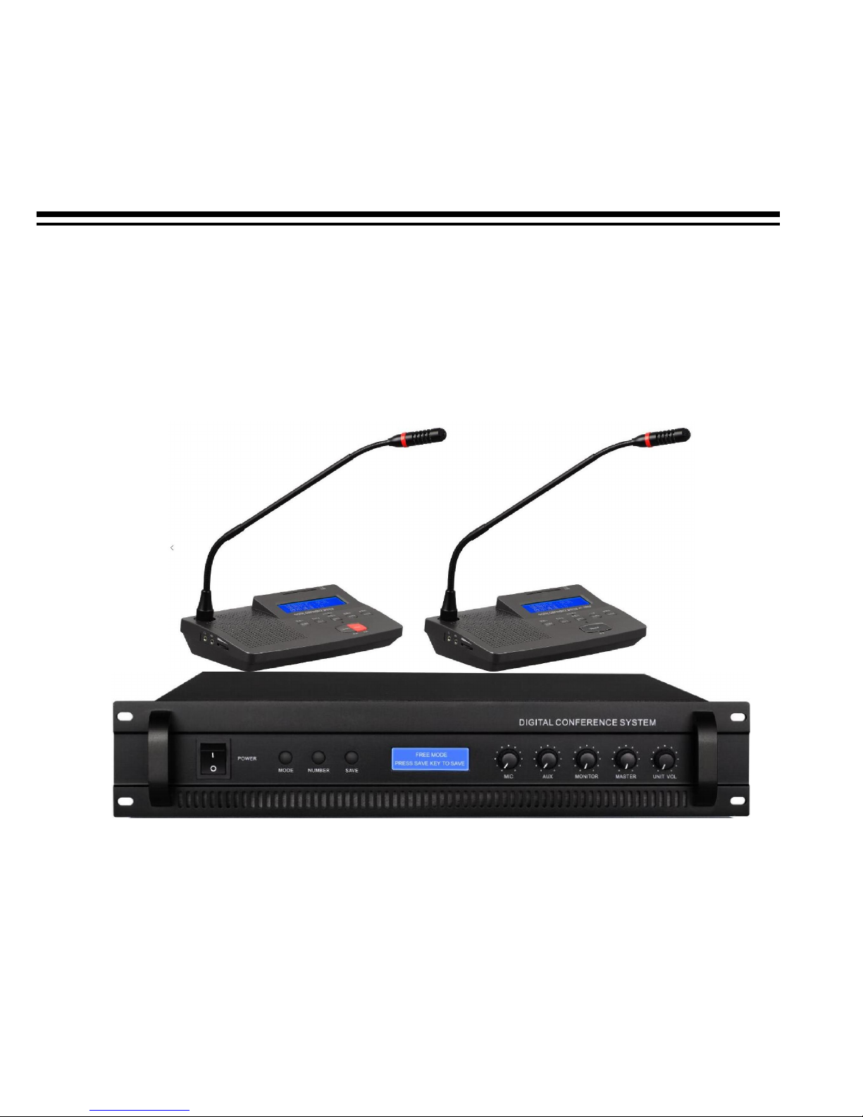
2. DESCRIPTION
This conference system uses digital technologies according to the European Community's IEC914 and ISO
standards.
It is composed of a main unit – H-7300 – and two microphone units – Delegate (H-7800d) and President (H7800c) – that feature high sensitivity, a wide frequency response, an internal loudspeaker and a cardioid
electret microphone with a lighted ring for the visual identification of the microphone in use. The system is
precabled to ensure fast and easy installation.
The device may include up to 64 microphone stations, daisy-chained on four independent lines (or a
maximum of 30 stations on each line).
The system involves the use of several expansion units – H-08EX. Every expansion unit can support up to
60 stations divided on six lines (never use more than 30 stations on each line).
Adding four expansion units, the system can control up to 254 stations.
The serial connection of each station is achieved through single multicore, prerouted cables that may be
used either for fixed or mobile systems.
Main Functions:
It directly powers and controls 64 microphone stations.
President station has priority on others.
Three operating modes: FREE MODE, LIMIT MODE and FIFO MODE
One microphone input (MIC) and one line input (LINE) for external units.
TAPE output for recordings and line output (LINE) for amplification (balanced and unbalanced).
It allows insertion of an audio processor to the chain.
Microphone sensitivity level control.
Loudspeaker level control for the unit monitors
Support video camera tracking and voting function
Product complies with CE regulations
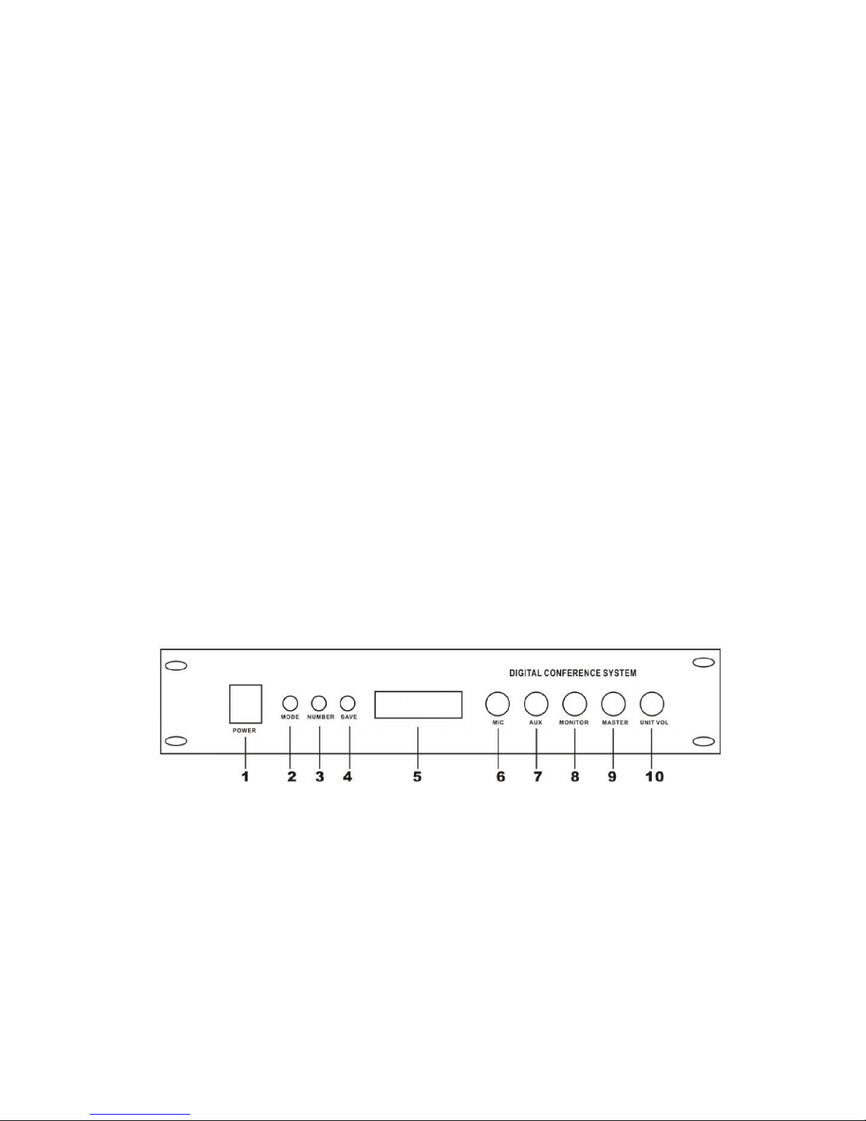
3. FRONT PANEL FUNCTIONS AND CONTROLS – H-7300
fig.1
1. POWER
Main power switch
2. MODE
Allows selection of one of the following modes:
FREE MODE, LIMIT MODE, FIFO MODE, C.ONLY MODE, MUSIC MODE and A.OFF MODE
3. SET
When LIMIT MODE or FIFO MODE are selected, it allows the user to limit the number of
simultaneous speakers taking part in the conference in addition to the President. Set a value
between 1 and 9
4. SAVE
Enables all selected settings
5. DISPLAY
Page 6
6
6. MIC
Sets the audio level of any dynamic microphone connected to MIC IN (fig. 2 – ref. 6)
7. AUX
Sets the audio level of any audio source (wireless microphone, CD player, etc.) connected to AUX
IN (figure 2 – ref. 7)
8. MONITOR
Sets the audio level of the monitor speaker on board the main unit
9. MASTER
Sets the level on MASTER OUT (figure 2 ref. 4, 5 )
10. UNIT VOL
Sets the audio level of the monitoring loudspeaker of the stations
(figure 3 – ref. 5 )
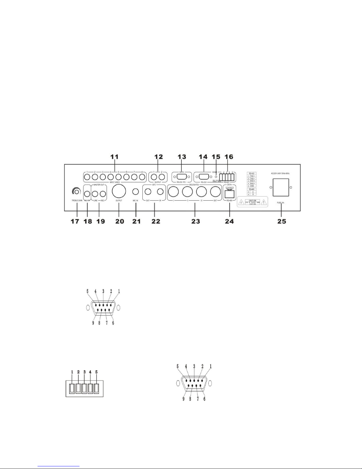
4. REAR PANEL FUNCTIONS AND CONTROLS - H-7300
fig.2
11. VIDEO CAMERA INPUTS
Connect these inputs to your camera. Up to 8 cameras max
12. VIDEO OUTPUT
Use this output to display camera video on an external video screen.
13. PC CONNECTOR
Connect this socket to your computer to setup the software function.
14-16.CAMERA CONTROL CONNECTOR RS-422
If you use dome in place of camera you can control pan and tilt move directly from software. Connect
this socket to the control connector of domes..
Note : To know connections, read the user manual of the dome.
RS-232
(PC)
female
1- NC
2- TXD
3- RXD
4- NC
5- GND
6- NC
7- NC
8- NC
9- NC
RS-4
22 (Green LED)
1- TXD +
2- TXD 3- RXD +
4- RXD –
5-
GND
RS-232 Male (Red LED)
1.NC
2.TXD
3.RXD
4.NC
5.GND
6.NC
7.NC
8.NC
9.NC
Page 7

7
17. TREBLE GAIN
Rotate this control counterclockwise to emphasize high frequencies
18. AUX IN
Line level input (RCA). Connect this input to an audio source such as a CD player, etc.
19. MASTER OUT LINE
Unbalanced line level output
20. MASTER OUT REG
Recording output (RCA). To record a conference, connect a recorder to this output
21. MIC IN
Microphone input (TRS Jack 6,3 mm)
22. EFXOUT / EFXIN
Balanced insert loop for any signal processor. p (TRS Jack 6,3 mm). Connect EFXOUT to the
PROCESSOR input and the PROCESSOR output to the EFXIN input
23. BASES
N° 4 input per President/Speaker unit. Up to 30 units can be connected to each line (do not exceed
this quantity), or up to 64 units total
24. DATA
Connect to this socket a central control system
25. AC POWER SOCKET
Power 230VAC 50/60Hz , FUSE 8A
5. PRESIDENT (H-7800c) AND DELEGATE (H-7800d) UNIT FUNCTIONS AND CONTROLS
fig.3
RJ-45
1- GND
2- GND
3- RS-485A+
4- RS-485B-
5- NC
6- NC
7- GND
8- GND
Page 8

8
1. Mono headset output (3,5 mm stereo jack)
When using the included mono headset, plug it into this output
2. REC output jack. 3.5mm jack, lavalier MIC jack of prisident unit
3. Vol knob
When using the knob, you can decrease or increase speaker monitor volume
4. Speaker Monitor
5. Candidate 1/Yes/LCD contrast +
6. Candidate 2/No/LCD contrast -
7. MIC ON/OFF
Press this button to speak (the station will be immediately enabled unless the limit of
simultaneously enabled stations has been reached), Press again to turn off microphone
8. PRIORITY
Press this button on the PRESIDENT station to disable all other speaker stations
9. --/Candidate 5/start vote( on chairman unit)
10. Sign-in IC card insert interface
11. 8-pin connection port
Connect the included cable to this port according to the following patterns
12. Microphone LCD display
13. Attend/Vote indicator
14. Candidate 3/ Abstain button
15. -/Candidate 4 /language select/LCD contrast/Reset( on chairman unit)
16. Power indicator
17. Indicator light on active microphone
When microphone is active, indicator light switches on
18. Microphone capsule
6. CONNECTION
Connect the unit to 230 V AC 50/60 Hz mains . Use the connection cables provided to connect the daisychained stations to the 4 BASE INPUTs (figure 2, ref. 23) as shown in figure 5, paying attention not to
connect more than 30 stations to each line and no more than 64 stations altogether.
Closed-loop lines can be created with the optional 3 m cable, as shown in figure 6. In this way no station
will be isolated in case of interruption one of the lines. The configuration shown in figure 6 cannot allow more
than 30 stations on each loop.
In any case, the maximum limit of 64 stations cannot be exceeded.
The system can host more than one PRESIDENT station. They can be inserted at any position on the chain.
If the system should support video camera track the conference management function, please connect the
system as per figure 7.
Page 9

9
fig.5
Page 10

10
fig.6
Page 11

11
Fig.7
Page 12

12
TYPE OF CONNECTIONS
Balanced connection:
Unbalanced connection:
Balanced connection with TRS jack
Unbalanced connection with TRS jack
Balanced connection on EUROBLOC connector
Unbalanced connection on EUROBLOC connector
RCA Connection
Page 13

13
7. HOW TO USE THE SYSTEM
Turn on H-7300, the controller LCD will display current working mode (fig1. ref.5)
MODES OF OPERATION:
FREE MODE
When this mode is selected, the display will read FREE MODE. In this mode, an unlimited number of
participants can speak simultaneously.
LIMIT MODE
When this mode is selected, this display will show LIMIT MODE, plus the number of delegates that
can speak simultaneously. Once this number of delegates is reached, no further delegates will be
allowed to intervene until the number of active delegate stations again falls below this limit.
FIFO MODE
When this mode is selected, the display will read FIFO MODE (First In-First Out), plus the number of
delegates who can speak simultaneously. In this mode, the H-7300 keeps track of the order in which
the delegate stations are activated. Once the preset limit of simultaneous delegates has been reached,
and a new delegate presses the MIC ON/OFF key (fig. 3 ref. 5) on his microphone base, the FIRST
station that was active when this limit was reached will be made inactive, and the new delegate station
will be activated.
Activation and Deactivation of previous Operating Modes
Using the MODE button (fig. 1 ref. 2), select the desired operating mode and press SAVE (fig. 1, ref. 4). If
the mode requires a numeric limit of delegates, this can be selected pressing the SET button (fig. 1, ref. 3)
and pressing SAVE to complete the setup.
FUNCTIONS:
C. ONLY MODE
When this function is activated, the display will show “C.ONLY MODE” followed by the check mark “√”.
When deactivated, the display will show “X” beside this function.
C.ONLY MODE √:
When the PRESIDENT presses the PRIORITY key (fig. 3, ref. 6), all DELEGATES will be
excluded, and the DELEGATE microphones will not reactivate when their MIC ON/OFF key is
pressed. These will remain excluded until the PRESIDENT again presses the MIC ON/OFF key.
C.ONLY MODE X:
When the PRESIDENT presses the PRIORITY key (fig. 3, ref. 6), all DELEGATES will be
excluded, but the DELEGATE microphones will be reactivated normally when their MIC ON/OFF
keys are pushed.
In either case (C.ONLY MODE “√” or “X”), the number of DELEGATES who can speak simultaneously
will be determined by the previously selected limit.
A. OFF MODE
When this function is activated, the display will read A.OFF MODE followed by the check mark “√”.
When deactivated, the display will show “X” beside this function.
A.OFF MODE √:
All activated DELEGATE stations will be automatically disactivated after 45 seconds of inactivity.
In order to speak again the delegate will have to press MIC ON/OFF again (fig. 3, ref. 5)
A.OFF MODE X:
There are no time limits for the activated DELEGATE bases
This function does not affect the PRESIDENT base
Page 14

14
MUSIC MODE
When this function is activated the display will read MUSIC MODE followed by the check mark “√”.
When deactivated, the display will show “X” beside this function.”
MUSIC MODE √:
When the PRESIDENT presses the PRIORITY button (fig. 3, ref. 6), the DELEGATE speaker
monitors will reproduce a warning tone.
MUSIC MODE X:
When the PRESIDENT presses the PRIORITY button (fig. 3, ref. 6), the DELEGATE speaker
monitor will not produce a warning tone
Activation/Deactivation of functions
Select a function using the scroll button MODE (fig. 1, ref. 2) and activate/disactivate pressing the SET
button (fig. 1, ref. 3)
Voting and Electing.
SIGN IN
The indicator lamp “ATTEND/VOTING” will flash when conference sign in start. Delegates sign in by IC
card and the “ATTEND” indicator in the vote unit will light, it means that delegates have sign in. Then
the vote unit can achieve other function.
VOTE
There are three buttons on the microphone unit for voting: yes/abstain/no. After voting starts, delegate
can press the corresponding button according to their willing. The delegate can re-vote before the
voting finishing if they want to revise their vote; the voting results are subject to last key-press. The
voting results will display in the LCD.
ELECT
There are five buttons on the microphone unit for electing: Candidate 1/2/3/4/5. After election starts,
delegate can press the corresponding button according to their willing. The delegate can re-elect before
the election finishing if they want to revise their elect; the election results are subject to last key-press.
Electing results will display in the LCD.
AUDIENCE RESPONSE
When conference start audience response, five button on the vote unit means: “--” (0), “-“(25), “0” (50),
“+” (75), “++” (100).
Voting and Electing can be organized by chairman microphone when system work without PC. The
chairman should press “Reset” button to finish and delete the data after voting and electing, then system
can be use other functions.
★
High-speed dome, video display card and software: Please read the camera and software manual
Page 15

15
8. FRONT PANEL FUNCTIONS AND CONTROLS - H-08EX
Fig.8
1. POWER
Main power switch
9. REAR PANEL FUNCTIONS AND CONTROLS - H-08EX
Fig.9
1. MAINS POWER INPUT
Connect main unit to 230 V AC 50/60 Hz mains.
8 A fuse socket.
2. EXPANDER OUTPUT
6 inputs for President/Delegate units. Each line can be connected to up to 30 stations (do not
connect more than 30). One H-08EX can manage up to 60 stations.
3. In-line Power Switches
After connecting the stations to the system, set the switches of the lines involved on the “I” position.
The LED light will indicate that the line is powered.
4. EXSPANDER LINK IN
Connect this input to one of the 4 H-7300 ouputs using the cable provided (fig. 2, ref. 2)
5. EXSPANDER LINK OUT
Connect this output to the next expansion unit input using the provided cable (fig. 9, ref. 4). There
is no limit to the number of expansion units that can be connected, yet the total number of
manageable microphone stations must not exceed 254.
Page 16

16
10. EXPANSION UNIT CONNECTION
Method 1:
fig.9
Note:
Be sure to keep the shortest possible distance between the central unit and the last microphone. For long
distances we advise opting for method 1.
Page 17

17
Method 2:
fig.10
Page 18

18
11. PACKAGE CONTENTS
H-7300: Central unit, Power cable, 13 meter main cable. RS232-USB cable, Software CD
H-08EX: Central unit, Power cable, 13 meter main cable (2 pieces), 3 meter main cable (2 pieces).
H-7800c: Base, connection cable, mono headset, IC card (option)
H-7800d: Base, connection cable, mono headset IC card (option)
12. TECHNICAL FEATURES
Model
H-
7300
H-
08EX
H-
7800
c/H-7800d
INPUT
BASES 8P-DIN socket/n°4 BUS 8P-DIN socket/n°6 BUS
MIC IN 6.3 TRS jack
AUX IN Unbalanced RCA
VIDEO IN RCA X8
OUTPUT
BAL OUT Balanced XLR3Male
LINE, REC Unbalanced RCA 3.5 mm stereo jack
HEADSET 3.5 mm stereo jack
VIDEO OUT RAC X2
S/N Radio >75 dB >75 dB >75 dB
Frequency
Response
20 Hz-18 kHz 20 Hz-18 kHz 20 Hz-18 kHz
T.H.D. <0.05% <0.05% <0.05%
Dimensions
(WxHxD)
482x90x353 mm
2U standard 19” rack
482x90x353 mm
2U standard 19” rack
Base: 205x55x150
Gooseneck: 390 mm
Weight 11.5 kg 10.2 kg 1.15 kg
Power
Consumption
350 W 350 W 2 W
Power supply
230 V AC 50/60 Hz
230 V AC 50/60 Hz
24 V DC by 8-PIN cable
This product complies with Directive 89/336/EEC (Electromagnetic Compatibility)
and later changes 92/31/EEC and 93/68/EEC, according to the following standards:
EN 50082-1:1997, EN 55013:1990, EN 55020:1994
furthermore, it complies with Directive 73/23/EEC (Low Voltage)
and later changes 93/68/CEE, according to the following standard:
EN 60065:1998
We maintains a policy of constant research and development, therefore we reserve the right to apply improvements to
existing equipment without prior notice
.
 Loading...