


2.4GHz Digital Wireless Receiver
Thank you for choosing our digital wireless surveillance product, which is the optimal choice to monitor those places like residences and offices.
The following are the brief introduction of main features of this product. Please read this user manual carefully before use.
I. Key Features:
*Digital Wireless Kit
100% Secure, Private Communication and Interference Free
*Work with 4 Cameras maximum
*One Channel View or Quad View
* Alarm-alert When Signal Dropout
*AV Output
VGA 30 frame(NTSC)/25 frame(PAL)
*Support DVR Connection for Recording
*
130m Outdoor/40m Indoor Transmission
II. Product Accessories Introduction
1. Camera (Bracket Included): 1pc (Support 4pcs Maximum)
2. Power Adapters: 2pcs (DC5V/1.5A)
3. Receiver (Receiver Stand Included) 1pc
4. AV Connection Cable: 1pc
5. User Manual: 1pc
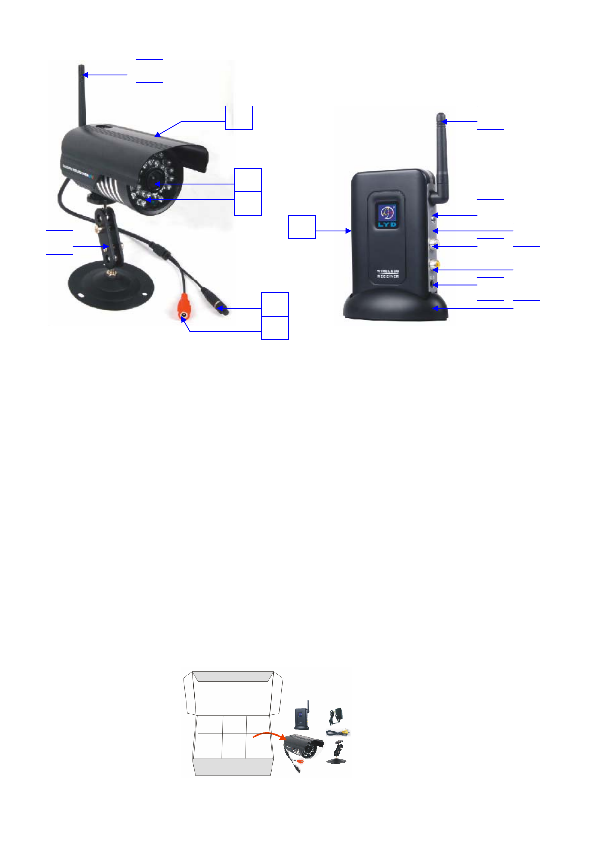
III. Product Structure:
1
1
2
8
3
4
11
7
9
10
12
13
14
5
1.Antenna for Wireless Camera, to strengthen the wireless signals.
2.Rainproof Housing of Camera, to enable the camera to be used outside the house.
3.Lens: the most important part of the camera. Please keep the lens clean so as to have better image. Please use special cleaning cloth to clean
the lens.
4.Night Vision LED: they help to get the image at night time.
5.Pairing Button: This button is used for code pairing with its receiver.
6.Power Adapter Plug for Camera: input 5V/1.5A Power Supply.
7.Bracket of the Camera
8.Antenna of the wireless receiver.
9.Channel Switching Button: Click for Channel Switching from Cam1 to Cam2, Cam3, Cam4, and Quad Image View. Press the Channel
Switching Button for 3 seconds for Code Pairing over this channel.
10.TV System (NTSC/PAL) Switching Hole: It is used for switching the TV system of the Camera kit. Because TV systems are various from
each country, you may need to set the TV system of the wireless camera kit to get a clear image.
11.Signal Indicator of the Receiver
12.Audio Out Plug of the Receiver
13.Video Out Plug of the Receiver
14.Power Adapter Plug for Receiver: Input 5V1.5A Power Supply
15.Stand for Receiver
6
15
IV. Product Installation
2
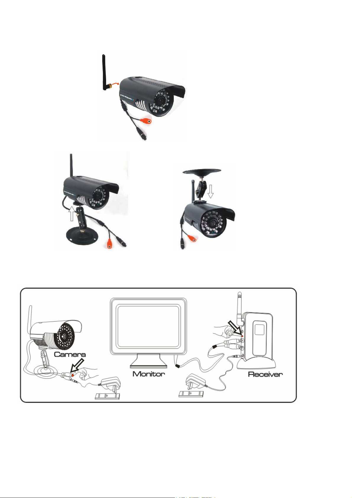
1. Take out the Camera, Receiver, Power Adapters and all the accessories from the package. (As shown below)
2. Install the antenna of the camera. (As shown below)
3. Install the bracket of the camera. There are two ways of bracket installation for your reference (A and B as shown below).
A B
4. Plug in the Power Adapters for the camera and receiver, and connect the AV cable between the receiver and the monitor. Then pair the code of the
camera and receiver to display the real-time i mage on the monitor. (As shown below). Please refer to “Code Matching Instructions” in Operation
Instruction 3.
5.After the Code Pairing is done, disconnect the power adapter of the camera and install the camera anywhere you like. You may need to contact
your local distributor to buy extended power cable in order to install the camera to more places.
3

6. Please make sure the Camera Power Adapter is well connected and the Receiver is well connected with the Monitor.
V. Operation Instruction:
1. Power On Instruction
Please connected the Receiver with the Monitor, and plug in the power adapter of the receiver, then you can view the following
image on the monitor.
1 2 3 4
1: Signal Bar
2. Wireless Camera Indication
3. FPS of wireless transmission
4. TV System Indication.
4

2. TV System Switching
It is used for switching the TV system of the Camera kit. Because TV sy stems are various from each country, you may need to set the TV system of
the wireless camera kit to get a clear image.
NTSC 制
PAL 制
3. Code Matching Instruction
1) Click the Channel Switching Button and Switch the Channel to Camera 1, and then press the Channel Switching Button for
3 seconds, then you will see the code matching notification on the monitor. (Shown as below)
2) Press the Pair Key of the camera within 30 seconds. (Shown as below)
5

3) The notification will disappear if the Code Pairing is successful, and the receiver starts to decode the image signal(usually
takes 5 seconds). (Shown as below)
You are going to view the image after the code pairing process is successfully done. (Shown as below)
4) Use the Same Method to complete the code pairing for Camera 2, Camera 3, or Camera 4. (If you have)
4. Image Display Switching.
After the code pairing process is completed, you can switch the viewing image by click the channel switching button from Cam1, Cam2,
Cam3, Cam4 and Quad View. (As shown below)
6

VI. Product Parameters:
General
Transmission Frequency: ISM 2.400-2.480 GHz
Transmission Power: 15dBm
Unobstructed Effective Range: 130m Outdoor/40m Indoor
Spread Spectrum: FHSS
Modulation Mode: GFSK
Operating T emperat ure: 14-122 Fahrenheit/-10-+50 Celsius
Operating Humidity: 85%
Camera
Imaging Sensor Type: CMOS
Picture T otal Pixels: 640*480pxl[NTSC]
Minimum Illumination: 0lux[IR on]
Night Vision Distance: 10m
Lens: 6.0mm
View Angle:
Consumption Current[Ma x]: Max850mA
Power Supply: 5V DC
Dimensions[W*D*H] 95mm*122MM*122MM
Weight: 0.45kg
Receiver
Display Feature
Resolution Supported:
Receiving Sensitivity: -81dbm
Consumption Current[Ma x]: 350mA
Power Supply: 5V DC
Dimensions[L*W*H]: 350mm*275mm*200mm
50°
[with antenna]
Single / QUAD Display
VGA(640*480)(NTSC/30Frame rate PAL/25Frame
rate )
7

Weight:
[with antenna attached]
VII. Troubleshooting:
1. Monitor Cannot display image:
Please make sure the AV cable is well connected between the monitor and receiver, and make sure the power adapters
for the receiver and the monitor are well connected too.
2. Flickering Image:
Please check if the TV System of the camera kit is set same with your local TV system.
3. Pause Display
A. The distance between the camera and receiver is beyond reception, or there are electromagnetic shield structures in
between.
B. High Power Transmitter for industrial use may cause interference of the wireless reception.
VIII. Safety Notice:
1.This product has micro-computer chip inside. Before using this product, please operating instructions carefully to know the functions clearly. It
will make you use it conveniently.
2.This product is designed for Home and Office Surveillance, any illegal operations are not allowed.
3.Do NOT remove the shell and housing of power adapter of the product, in case of the electric shock.
4. The front cover of the camera is made of glass, please use it with care, and place it out of the reach of children.
5. Please use the attached power adapters of this product.
6. Never make any conductive objects in touch with the front tip of power adapters, which otherwise might result in electric shock or fire hazard.
7. Please place all the accessories and Camera kit beyond the reach of children.
It states that this product is only for the use of normal monitoring, and any illegal operations are not allowed. Our company
shall not be responsible for any harmful consequences arising from.
8

9
 Loading...