

Lycoming IO-360-N1A Installation And Operation Manual

Engine Installation and Operation Manual
IO-360-N1A Engine
February 2016
Part No. IOM-IO-360-N1A
© 2016 Avco Corporation. All Rights Reserved.

Factory
U.S. and Canada Toll Free:
Direct:
+1 (800) 258-3279
+1 (570) 323-6181
Installation and Operation Manual
Lycoming Part Number: IOM-IO-360-N1A
Contact Us:
Mailing Address:
Lycoming Engines
652 Oliver Street
Williamsport, PA 17701 USA
IO-360-N1A Engine
Phone:
Lycoming’s regular business hours are Monday through Friday from 8:00AM through 5:00PM
Eastern Time (-5 GMT).
Visit us Online: www.Lycoming.com

IO-360-N1A Engine Installation and Operation Manual
Revision
Revision
Date
Revised
By
Revision Description
Original
Original Release of Installation and Operation Manual - Part No.
IOM-IO-360-N1A
RECORD OF REVISIONS
© 2016 Avco Corporation. All Rights Reserved Record of Revisions
February 2016 Page i

IO-360-N1A Engine Installation and Operation Manual
This page intentionally left blank.
Record of Revisions © 2016 Avco Corporation. All Rights Reserved
Page ii February 2016

IO-360-N1A Engine Installation and Operation Manual
Number
Incorporation
Date
Subject
S.B. 369
02/16
Engine Inspection after Overspeed
S.B. 480
02/16
I. Oil and Filter Change and Screen Cleaning
II. Oil Filter Screen Content Inspection
S.B. 533
02/16
Recommended Action for Sudden Engine Stoppage,
Propeller/Rotor Strike or Loss of Propeller/Rotor
Blade or Tip
S.I. 1009
02/16
Recommended Time Between Overhaul Periods
S.I. 1014
02/16
Lubricating Oil Recommendations
S.I. 1070
02/16
Specified Fuels
S.I. 1098
02/16
Propeller Flange Bushing Location
S.I. 1132
02/16
Magneto Drop-off
S.I. 1154
02/16
FAA Approved Starter and Alternators
S.I. 1241
02/16
Pre-oil the Engine Prior to Initial Start
S.I. 1409
02/16
Lycoming Engines P/N LW-16702, Oil Additive
S.I. 1427
02/16
Lycoming Reciprocating Engine Run-In and Oil
Consumption
S.I. 1443
02/16
Approved Slick Magnetos on Lycoming Engines
S.I. 1472
02/16
Removal of Preservative Oil from Engine
S.I. 1481
02/16
Factory Engine Preservation
S.I. 1505
02/16
Cold Weather Starting
S.I. 1528
02/16
Aircraft Engine Starter Recommendations
S.I. 1530
02/16
Engine Inspection in a Particulate Laden
Environment (Volcanic Ash, Sand, Dust, Airborne
Debris)
L 114
02/16
Reciprocating Engine and Accessory Maintenance
Publications
L180
02/16
Engine Preservation for Active and Stored Aircraft
SERVICE DOCUMENT LIST
NOTICE: The following is a list of service documents referenced in or incorporated into the
information in this manual. Always refer to the latest revision of any service document
for changes or additional information.
© 2016 Avco Corporation. All Rights Reserved Service Document List
February 2016 Page iii

IO-360-N1A Engine Installation and Operation Manual
This page intentionally left blank.
Service Document List © 2016 Avco Corporation. All Rights Reserved
Page iv February 2016

IO-360-N1A Engine Installation and Operation Manual
TABLE OF CONTENTS
Section Page
Frontal __________________________________________________________________________
Record of Revisions .............................................................................................................................. i
Service Document List ....................................................................................................................... iii
Table of Contents ................................................................................................................................ v
List of Figures ..................................................................................................................................... ix
List of Tables ...................................................................................................................................... xi
Abbreviations and Acronyms ......................................................................................................... xiii
Introduction ....................................................................................................................................... xv
System Description ________________________________________________________________
— System Description ................................................................................................................... 1
— Cylinders ................................................................................................................................... 1
— Crankcase .................................................................................................................................. 2
— Ignition System ......................................................................................................................... 2
— Starter ........................................................................................................................................ 3
— Fuel Injection System................................................................................................................ 4
— Lubrication System ................................................................................................................... 4
— Cylinder Number Designations ................................................................................................. 5
Engine Reception and Lift __________________________________________________________
— Uncrate Procedure for a New, Rebuilt, or Overhauled Engine ................................................. 7
— Acceptance Check ..................................................................................................................... 7
— Engine Preservative Oil Removal ............................................................................................. 8
— Lift the Engine .......................................................................................................................... 8
Requirements for Engine Installation ________________________________________________
— Overview ................................................................................................................................... 9
— Step 1. Prepare the Engine ........................................................................................................ 9
— Step 2. Supply Interface Items ................................................................................................ 14
— Step 3. Remove Components .................................................................................................. 15
— Step 4. Install Aircraft-Supplied Engine Mounts .................................................................... 15
— Step 5. Prepare the Aircraft Engine Harness ........................................................................... 15
— Step 6. Make Electrical Interface Connections ....................................................................... 15
© 2016 Avco Corporation. All Rights Reserved Table of Contents
February 2016 Page v

IO-360-N1A Engine Installation and Operation Manual
Section Page
Engine Installation ________________________________________________________________
— Engine Installation Overview .................................................................................................. 17
— Step 1. Install the Engine on Mounts ...................................................................................... 18
— Step 2. Connect the Wiring Harness ....................................................................................... 18
— Step 3. Connect the Linkages .................................................................................................. 18
— Step 4. Install External Accessories (as necessary) ................................................................ 18
— Step 5. Install Baffling ............................................................................................................ 18
— Step 6. Install the Compressor Belt (as necessary) ................................................................. 18
— Step 7. Install the Propeller ..................................................................................................... 18
— Step 8. Connect Fuel Lines ..................................................................................................... 19
— Step 9. Connect Oil Lines ....................................................................................................... 19
— Step 10. Install Components That Had Been Removed Before Engine Installation............... 20
— Step 11. Add Oil...................................................................................................................... 20
— Step 12. Add Fuel.................................................................................................................... 21
— Step 13. Engine Pre-Oil Procedure ......................................................................................... 21
Engine Start and Operation ________________________________________________________
— Warranty Requirement ............................................................................................................ 23
— Before Engine Start ................................................................................................................. 23
— Engine Run-In / Engine Break-In ........................................................................................... 23
— Step 1. Prepare an Engine for First Time Operation ............................................................... 24
—Pre-Flight Inspection for First Time Operation Checklist .................................................. 25
— Step 2. Start the Engine ........................................................................................................... 26
—Magnetic Drop-Off Check .................................................................................................. 28
— Step 3. Complete the Engine Run-Up ..................................................................................... 28
— Step 4. Operate the Engine ...................................................................................................... 29
—Operation in Flight .............................................................................................................. 29
—Fuel Mixture Leaning.......................................................................................................... 29
— Step 5. Stop the Engine ........................................................................................................... 30
Table of Contents © 2016 Avco Corporation. All Rights Reserved
Page vi February 2016

IO-360-N1A Engine Installation and Operation Manual
Section Page
Engine Conditions ________________________________________________________________
— Action for Engine Conditions ................................................................................................. 31
—Apply Heat to a Cold Engine .............................................................................................. 32
—Cold Weather Start .............................................................................................................. 33
—Engine Operation in Hot Weather ....................................................................................... 34
—Volcanic Ash ....................................................................................................................... 34
—Overspeed............................................................................................................................ 35
—Low Oil Pressure During Flight .......................................................................................... 35
Flight Test _______________________________________________________________________
— Flight Test ............................................................................................................................... 37
Engine Preservation and Storage ____________________________________________________
— Engine Corrosion and Prevention ........................................................................................... 39
— Engine Preservation - 30 to 60 Days ....................................................................................... 40
— Fuel Injector Preservation ....................................................................................................... 42
— Engine Preservation - 61 to 180 Days ..................................................................................... 42
— Engine Preservation - 181 Days or More ................................................................................ 43
— Cold Weather Storage ............................................................................................................. 43
— Long-Term Storage of Engines that Use Automotive Fuel .................................................... 43
Appendix ________________________________________________________________________
— Appendix A - Engine Specifications and Operating Limits ................................................... 45
— Appendix B - Installation and Wiring Diagrams .................................................................... 49
— Appendix C - Performance Data ............................................................................................. 51
© 2016 Avco Corporation. All Rights Reserved Table of Contents
February 2016 Page vii

IO-360-N1A Engine Installation and Operation Manual
This page intentionally left blank.
Table of Contents © 2016 Avco Corporation. All Rights Reserved
Page viii February 2016

IO-360-N1A Engine Installation and Operation Manual
Fig. No.
Figure Title
Page
System Description Section
1
IO-360-N1A Engine
1 2 Engine Cylinder
1 3 Crankcase
2 4 Crankshaft
2 5 Ignition System
3 6 Starter
3 7 Fuel Injection System
4 8 Lubrication System
4 9 Cylinder Number Designation
5
Engine Reception and Lift Section
1
Engine Data Plate
7 2 Engine Lift
8
Engine Installation
1
Oil Fill Tube and Oil Level Gage (Dipstick)
20
Appendix C - Performance Data
C-1
Sea Level and Altitude Performance
51
C-2
Minimum Fuel Flow vs. Nozzle Pressure
52
C-3
Fuel Consumption vs. Actual Brake Horsepower
53
C-4
Cooling Air Requirements
54
LIST OF FIGURES
© 2016 Avco Corporation. All Rights Reserved List of Figures
February 2016 Page ix

IO-360-N1A Engine Installation and Operation Manual
This page intentionally left blank.
List of Figures © 2016 Avco Corporation. All Rights Reserved
Page x February 2016

IO-360-N1A Engine Installation and Operation Manual
Table
No.
Table Title
Page
Requirements for Engine Installation Section
1
Prerequisites for Engine Installation
9
2
Optional Equipment, Recommendations, and Requirements to Prepare
the Engine for Installation
14
Engine Installation Section
1
Aircraft Where IO-360-N1A Engines Can Be Installed
17 2 Aircraft Where IO-360-N1A Engines Cannot be Installed
17 3 Engine Installation Steps and References
17
Engine Start and Operation Section
1
Prerequisite Requirements for Engine Operation
23
Engine Conditions Section
1
Action for Engine Conditions
31
Appendix A - Engine Specifications and Operating Limits
A-1
IO-360-N1A Engine Specifications
45
A-2
Table of Operating Limits for IO-360-N1A Engine
47
A-3
Accessory Drives for IO-360-N1A Engines
48
LIST OF TABLES
© 2016 Avco Corporation. All Rights Reserved List of Tables
February 2016 Page xi

IO-360-N1A Engine Installation and Operation Manual
This page intentionally left blank.
List of Tables © 2016 Avco Corporation. All Rights Reserved
Page xii February 2016

IO-360-N1A Engine Installation and Operation Manual
A
Amp
Ampere
B
BHP
Brake Horsepower
BSFC
Brake Specific Fuel Consumption
Btu
British Thermal Unit
C
C
Celsius
CHT
Cylinder Head Temperature
cm
Centimeter
E
EGT
Exhaust Gas Temperature
EPA
Environmental Protection Agency
F
F
Fahrenheit
FAA
Federal Aviation Administration
FAR
Federal Aviation (and Space) Regulation
FOD
Foreign Object Debris
Ft.-lb
Foot Pound (torque)
G
G
Force of Gravity
H
HET
Hartzell Engine Technologies
Hg
Mercury
HP
Horsepower
I
ICA
Instructions for Continued Airworthiness
in.-lb
Inch Pound (torque)
in.
Inch, inches
In-Hg
Inches of Mercury
L
lb
Pound
LL
Low Lead (fuel)
ABBREVIATIONS AND ACRONYMS
© 2016 Avco Corporation. All Rights Reserved Abbreviations and Acronyms
February 2016 Page xiii

IO-360-N1A Engine Installation and Operation Manual
M
mm
Millimeter
MSB
Mandatory Service Bulletin
N
Nm
Newton Meter
P
P/N
Part Number
POH
Pilot’s Operating Handbook
ppm
Particles per Million
psi
Pounds per Square Inch
R
rpm
Revolutions per Minute
S
SAE
Society of Automotive Engineers (oil viscosity)
SB
Service Bulletin
SI
Service Instruction
STC
Supplemental Type Certificate
T
TCM
Teledyne Continental Motors
TR
Temporary Revision
V
V
Volt, Voltage
ABBREVIATIONS AND ACRONYMS (CONT.)
Abbreviations and Acronyms © 2016 Avco Corporation. All Rights Reserved
Page xiv February 2016
IO-360-N1A Engine Installation and Operation Manual
Model Number
Meaning
I
Fuel Injected
O
Horizontally Opposed
360
Displacement in cubic inches
INTRODUCTION
Engine Model Nomenclature
The tables below show the definition of each letter and number for IO-360-N1A engines.
Scope of this Manual
This manual supplies instructions (in compliance with FAR 33.5 and 21.50) for engine preparation,
installation, and operation of the IO-360-N1A Lycoming aircraft engines. The installation
instructions in this manual are basic guidelines. When installing the engine in the airframe, follow
the airframe manufacturer’s installation instructions.
Refer to the IO-360-N1A Engine Service Manual for required maintenance (service information)
such as: oil changes, oil addition, oil filter replacement, routine time-interval inspections, routine
service, spark plug replacement/inspection procedures, cylinder inspection, fuel system inspection,
and scheduled servicing procedures.
For airworthiness limitations, guidelines to isolate faults and for procedures to replace components,
disassemble and assemble the engine, refer to the IO-360-N1A Engine Maintenance Manual.
For spare parts information, refer to the IO-360-N1A Illustrated Parts Catalog.
Refer to the latest revision of the Service Table of Limits - SSP-1776, for dimensions, clearances,
measurements, and torque values.
Service Bulletins, Service Instructions, and Service Letters
As advancements in technological applications on this engine continue, Lycoming will make future
revisions to this manual. However, if more timely distribution is necessary, Lycoming supplies
subscribers with up-to-date Service Bulletins (SBs), Service Instructions (SIs) and Service Letters
(which are abbreviated with a capital “L” followed by the number, example L180). Special
Advisories (SAs) are supplied as necessary without a subscription.
For subscription information, look on Lycoming’s website or speak to Lycoming by telephone: U.S.
and Canada toll free: 1-800-258-3279; International Customers: 570-323-6181.
Applicable information from Lycoming Service Bulletins, Service Instructions, and Service Letters
are included in this manual at the time of publication. Any new service information will be included
in the next update of the manual.
For reference and future updates, the Service Document List at the front of this manual shows the
editions of the service documents included in this manual.
Instructions for Continued Airworthiness
The IO-360-N1A Engine Service Manual, IO-360-N1A Engine Maintenance Manual, latest
revision of the Service Table of Limits - SSP-1776, service documents, and related publications
make up the complete set of Instructions for Continued Airworthiness (ICAs). The ICAs are
prepared by Lycoming Engines and are approved by the Federal Aviation Administration (FAA).
© 2016 Avco Corporation. All Rights Reserved Introduction
February 2016 Page xv
IO-360-N1A Engine Installation and Operation Manual
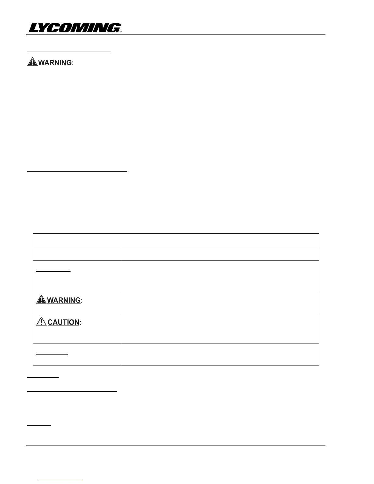
Safety Advisory Conventions
Advisory Word
Definition
DANGER:
Indicates a hazardous situation which, if not avoided, will result
in death or serious injury. This signal word is to be limited to the
most extreme situations.
Indicates a hazardous situation which, if not avoided, could
result in death or serious injury.
Indicates a hazardous situation which, if not avoided, could
result in minor or moderate injury. It can also be used without
the safety alert symbol as an alternative to "NOTICE."
NOTICE:
The preferred signal word to address practices not related to
personal injury.
Compliance Requirements
OPERATE THIS ENGINE IN ACCORDANCE WITH SPECIFICATIONS IN
APPENDIX A OF THIS MANUAL. OPERATING THE ENGINE BEYOND
SPECIFIED OPERATING LIMITS CAN CAUSE PERSONAL INJURY
AND/OR DAMAGE TO THE ENGINE.
YOU ALSO MUST COMPLETE THE NECESSARY SERVICE
PROCEDURES IDENTIFIED IN LYCOMING ENGINES' SERVICE
MANUAL FOR THIS ENGINE AS WELL AS ANY APPLICABLE SERVICE
DOCUMENTS. LYCOMING ENGINES' SERVICE DOCUMENTS
OVERRIDE PROCEDURES IN THIS MANUAL.
PROCEDURES IN THE SERVICE MANUALS MUST BE DONE BY
QUALIFIED PERSONNEL WITH THE REQUISITE CERTIFICATIONS.
Warning, Cautions, and Notices
Be sure to read and obey the Warnings, Cautions and Notices in this manual and in service
documents. Although Lycoming cannot know all possible hazards or damages, it makes a reasonable
effort to supply the best possible guidance and recommended practices for safe operation of its
engines.
The table below defines the four types of safety advisory messages used in this manual per the
American National Standard and ANSI Z535-6-2006.
NOTICE: In this manual, the word "recommended" refers to "best practices."
Simplified Technical English
The text in the manual is written in the form of Simplified Technical English in compliance with
FAA requirements and to make translation into other languages easier.
Figures
Figures in this manual are for conceptual illustrative purposes only.
Introduction © 2016 Avco Corporation. All Rights Reserved
Page xvi February 2016

IO-360-N1A Engine Installation and Operation Manual
Copyright
This publication is a copyrighted work. All rights reserved by Lycoming Engines. Content in this
manual cannot be changed or released as a reprint, electronic media output, or web communiqué
without written permission from Lycoming Engines.
Environmental Compliance
Lycoming Engines recommends that engine owners and engine service personnel be in compliance
with all federal, state, and local environmental regulations when solvents, paint, fuel, oil, chemicals,
or other consumables are used in engine service.
Supplemental Service Information
Refer to the latest revision of Service Letter No. L114 for a list of Lycoming publications available
for purchase.
Feedback
To supply comments, suggestions, or corrections to this manual, either make a call to customer
service or use the Lycoming.com website.
Customer Service
Lycoming has a Customer Service Hot Line to supply information and assistance to owners,
operators, and maintenance personnel servicing Lycoming engines.
Phone:
Factory: U.S. and Canada toll free - +1 (800) 258-3279
International Customers - +1 (570) 323-6181
Sales Department: +1 (570) 327-7278
Fax: +1 (570) 327-7101
Lycoming’s regular business hours are Monday through Friday from 8:00 A.M. through 5:00
P.M. Eastern Time (-5 GMT)
Change of Address Notification
The owner of the manual is responsible to supply of a change of address to Lycoming Engines.
© 2016 Avco Corporation. All Rights Reserved Introduction
February 2016 Page xvii

IO-360-N1A Engine Installation and Operation Manual
This page intentionally left blank.
Introduction © 2016 Avco Corporation. All Rights Reserved
Page xviii February 2016
IO-360-N1A Engine Installation and Operation Manual
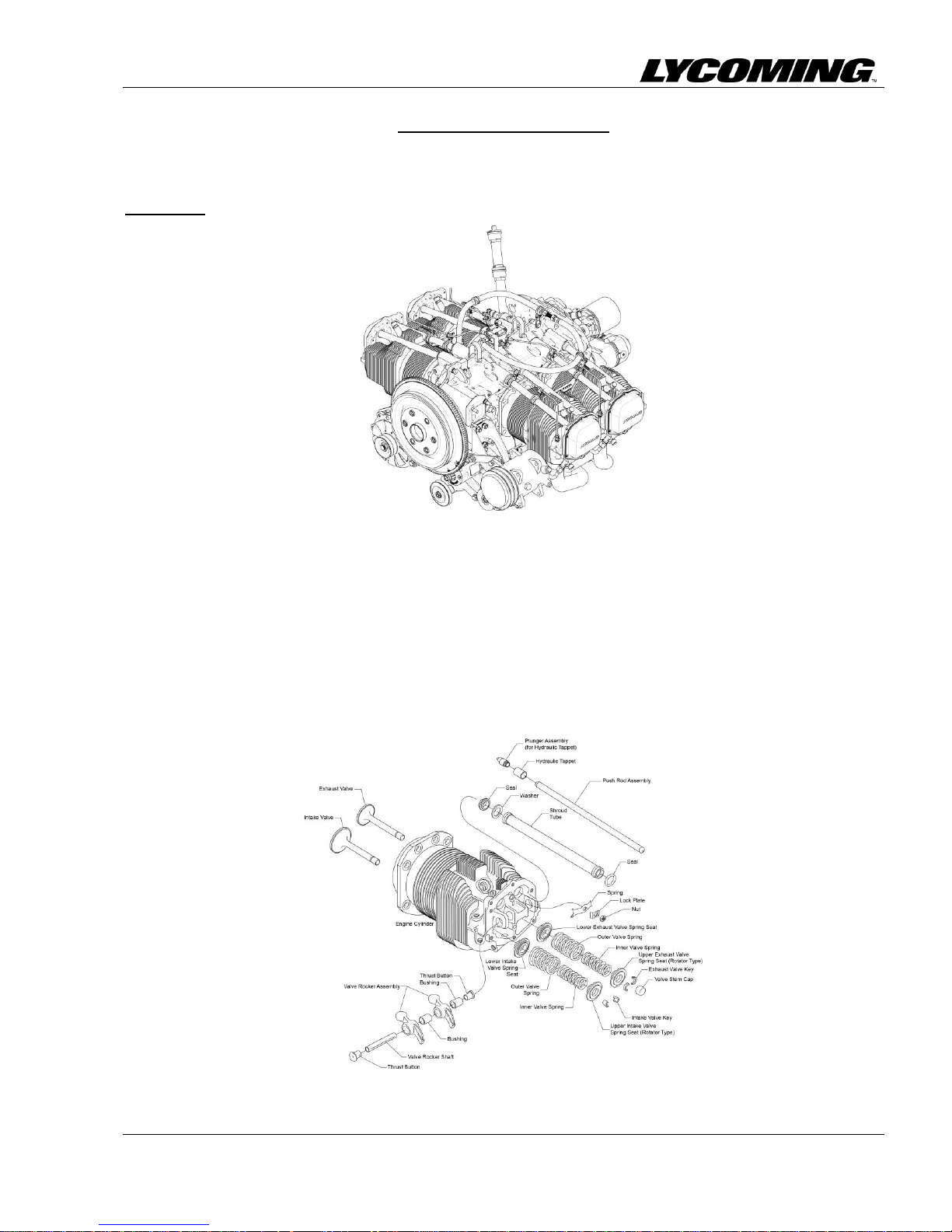
SYSTEM DESCRIPTION
The Lycoming IO-360-N1A engine (Figure 1) is a direct-drive four-cylinder, horizontally opposed,
fuel-injected, air-cooled engine. It has tuned induction, and a down exhaust.
NOTICE: Refer to Appendix C for engine performance data.
Figure 1
IO-360-N1A
Cylinders
There are four cylinders on this engine. Each cylinder (Figure 2) contains a cylinder head, barrel,
piston, parallel intake and exhaust valve guides and valve seats, rocker shafts, rocker covers, and
fins.
Fuel and air enter the cylinder through the cylinder head for mixing and combustion within the
cylinder.
The engine has intercylinder cooling baffles.
Figure 2
Engine Cylinder
© 2016 Avco Corporation. All Rights Reserved System Description
February 2016 Page 1
IO-360-N1A Engine Installation and Operation Manual
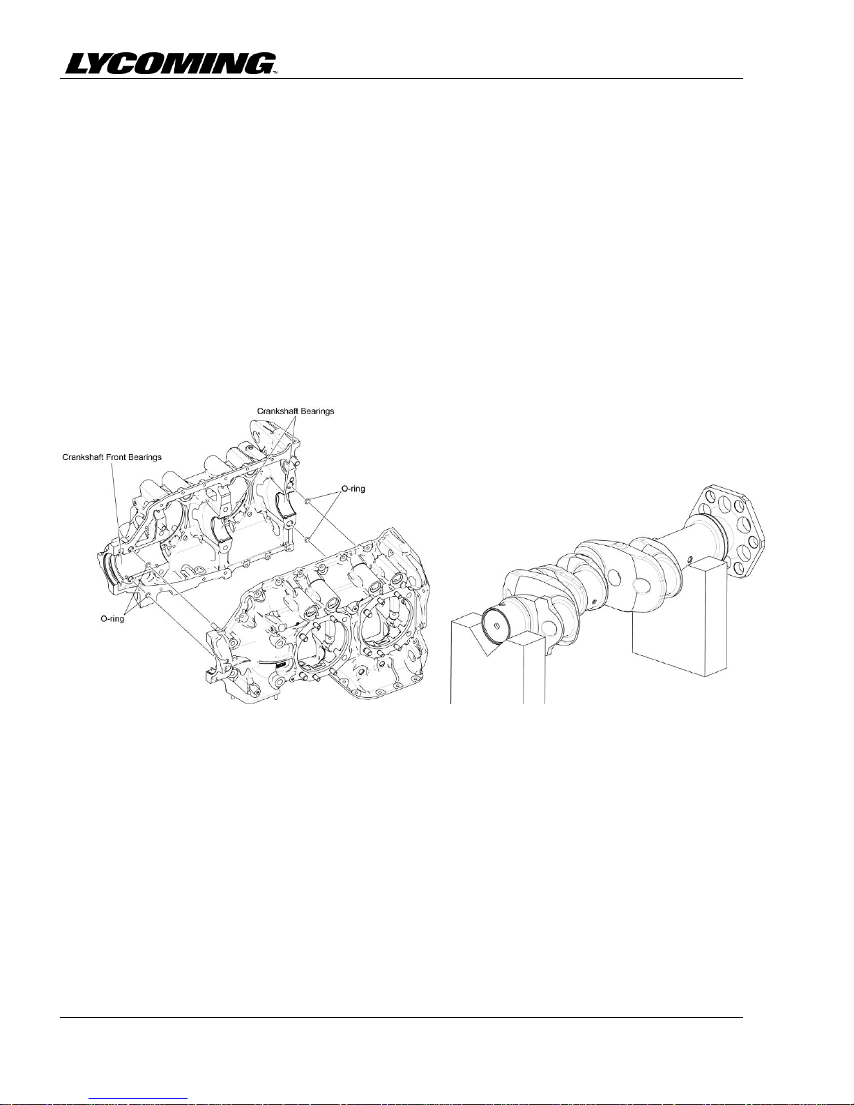
Figure 3
Crankcase
Figure 4
Crankshaft
Crankcase
The crankcase (Figure 3) is made up of two casting halves attached by a series of through-studs,
bolts and nuts.
The crankcase forms the bearings for the camshaft. The camshaft operates the tappets which control
opening and closing of the intake and exhaust valves. The camshaft has an integral spur gear that
drives the propeller governor output shaft.
The main bearing bores are machined for precision-type main bearing inserts. The crankshaft mainbearings are pairs of inserts installed in the crankcase at each journal.
The crankshaft (Figure 4) is within the crankcase. The crankshaft has journals to attach connecting
rods and pistons.
Oil is supplied through the propeller flange for a single-acting controllable pitch propeller.
Four oil nozzles supply oil for internal piston cooling
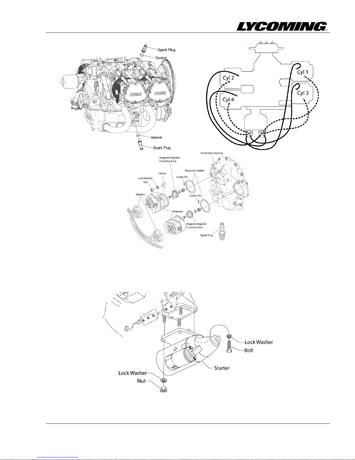
Ignition System
The all weather-shielded ignition system (Figure 5) includes:
Eight spark plugs (two per cylinder)
Ignition harness
Two magnetos (identified in Appendix A).
One magneto can have one retard breaker magneto and one plain magneto. The plain magneto must
be grounded during the start cycle. The shafts in both magnetos rotate clockwise (when facing the
drive pad).
System Description © 2016 Avco Corporation. All Rights Reserved
Page 2 February 2016
IO-360-N1A Engine Installation and Operation Manual
Figure 5
Ignition System
Starter
The engine can have either a 12V or 24V starter (Figure 6). Refer to Appendix A.
© 2016 Avco Corporation. All Rights Reserved System Description
February 2016 Page 3
Figure 6
Starter
 Loading...