

Page 1

NOTE
In order to accommodate clearer type, larger charts and graphs, and more
detailed illustrations, this edition of the O-360, HO-360, IO-360, AIO-360,
HIO-360 and TIO-360 Operator’s Manual, Lycoming Part Number
60297-12, is presented in an 8-1/2 x 11 inch format. This edition is a
complete manual, current as of the date of issue. The manual incorporates
all previously issued revisions.
This manual will be kept current by revisions available from Lycoming
distributors or from the factory. All revisions will be accompanied by an
Operator’s Manual Revision page which will identify the revision level, the
date of the revision, and the pages revised, added or deleted. All revisions
will be supplied in the 8-1/2 x 11 inch format.
Page 2
Operator’s Manual
Lycoming
O-360, HO-360,
IO-360, AIO-360,
HIO-360 & TIO-360 Series
Approved by FAA
8thEdition Part No. 60297-12
652 Oliver Street
Williamsport, PA. 17701 U.S.A.
October 2005
570/323-6181
Page 3

OPERATORS MANUAL
REVISION
REVISION NO. PUBLICATION PUBLICATION NO. PUBLICATION DATE
60297-12-4
O-360, HO-360, IO-360,
AIO-360, HIO-360 &
TIO-360 Series
60297-12 October 2005
The page(s) in this revision replace, add to, or delete current pages in the operators manual.
PREVIOUS REVISION CURRENT REVISION
June 2007
Web Page; 3-38
September 2007
3-8, 3-9, 3-11
December 2007
3-4, 3-5
March 2009
1-5; Section 2 Index, 2-3, 2-8, 2-11; 3-5, 3-21, 3-41
©2009 by Lycoming All Rights Reserved
Lycoming Engines, a division of AVCO Corporation, a wholly owned subsidiary of Textron Inc.
Page 4

OPERATOR’S MANUAL
REVISION
REVISION NO. PUBLICATION PUBLICATION NO. PUBLICATION DATE
60297-12-3
O-360, HO-360, IO-360,
AIO-360, HIO-360 &
TIO-360 Series
60297-12 October 2005
The page(s) in this revision replace, add to, or delete current pages in the operator’s manual.
PREVIOUS REVISION CURRENT REVISION
June 2007
Web Page; 3-38
September 2007
3-8, 3-9, 3-11
December 2007
3-4, 3-5
Page 5

OPERATOR’S MANUAL
REVISION
REVISION NO. PUBLICATION PUBLICATION NO. PUBLICATION DATE
60297-12-2
O-360, HO-360, IO-360,
AIO-360, HIO-360 &
TIO-360 Series
60297-12 October 2005
The page(s) in this revision replace, add to, or delete current pages in the operator’s manual.
PREVIOUS REVISION CURRENT REVISION
June 2007
Web Page; 3-38
September 2007
3-8, 3-9, 3-11
Page 6

OPERATOR’S MANUAL
REVISION
REVISION NO. PUBLICATION PUBLICATION NO. PUBLICATION DATE
60297-12-1
O-360, HO-360, IO-360,
AIO-360, HIO-360 &
TIO-360 Series
60297-12 October 2005
The page(s) in this revision replace, add to, or delete current pages in the operator’s manual.
PREVIOUS REVISION CURRENT REVISION
None
June 2007
Web Page; 3-38
Page 7

O, HO, IO, AIO, HIO, TIO-360 Series Operator’s Manual
Lycoming Part Number: 60297-12
©2005 by Lycoming. All rights reserved.
Lycoming and “Powered by Lycoming” are trademarks or registered trademarks of
Lycoming.
All brand and product names referenced in this publication are trademarks or registered
trademarks of their respective companies.
For additional information:
Mailing address:
Lycoming Engines
652 Oliver Street
Williamsport, PA 17701 U.S.A.
Phone:
Factory: 570-323-6181
Sales Department: 570-327-7268
Fax: 570-327-7101
Lycoming’s regular business hours are Monday through Friday from 8:00 AM
through 5:00 PM Eastern Time (-5 GMT)
Visit us on the World Wide Web at:
http://www.lycoming.com
Revised June 2007
Page 8

LYCOMING OPERATOR’S MANUAL
ATTENTION
OWNERS, OPERATORS, AND MAINTENANCE PERSONNEL
This operators manual contains a description of the engine, its specifications, and detailed information on
how to operate and maintain it. Such maintenance procedures that may be required in conjunction with
periodic inspections are also included. This manual is intended for use by owners, pilots and maintenance
personnel responsible for care of Lycoming powered aircraft. Modifications and repair procedures are
contained in Lycoming overhaul manuals; maintenance personnel should refer to these for such procedures.
SAFETY WARNING
NEGLECTING TO FOLLOW THE OPERATING INSTRUCTIONS AND TO CARRY OUT PERIODIC
MAINTENANCE PROCEDURES CAN RESULT IN POOR ENGINE PERFORMANCE AND POWER
LOSS. ALSO, IF POWER AND SPEED LIMITATIONS SPECIFIED IN THIS MANUAL ARE EXCEEDED,
FOR ANY REASON; DAMAGE TO THE ENGINE AND PERSONAL INJURY CAN HAPPEN. CONSULT
YOUR LOCAL FAA APPROVED MAINTENANCE FACILITY.
SERVICE BULLETINS, INSTRUCTIONS, AND LETTERS
Although the information contained in this manual is up-to-date at time of publication, users are urged to
keep abreast of later information through Lycoming Service Bulletins, Instructions and Service Letters
which are available from all Lycoming distributors or from the factory by subscription. Consult the latest
revision of Service Letter No. L114 for subscription information.
SPECIAL NOTE
The illustrations, pictures and drawings shown in this publication are typical of the subject matter they
portray; in no instance are they to be interpreted as examples of any specific engine, equipment or part
thereof.
iii
Page 9

LYCOMING OPERATOR’S MANUAL
IMPORTANT SAFETY NOTICE
Proper service and repair is essential to increase the safe, reliable operation of all aircraft engines. The
service procedures recommended by Lycoming are effective methods for performing service operations.
Some of these operations require the use of tools specially designed for the task. These special tools must be
used when and as recommended.
It is important to note that most Lycoming publications contain various Warnings and Cautions which
must be carefully read in order to minimize the risk of personal injury or the use of improper service
methods that may damage the engine or render it unsafe.
It is also important to understand that these Warnings and Cautions are not all inclusive. Lycoming could
not possibly know, evaluate or advise the service trade of all conceivable ways in which service might be
done or of the possible hazardous consequences that may be involved. Accordingly, anyone who uses a
service procedure must first satisfy themselves thoroughly that neither their safety nor aircraft safety will be
jeopardized by the service procedure they select.
iv
Page 10

WARRANTY
NEW AND REBUILT ENGINES
(1) WARRANTY AND REMEDY: Lycoming Engines, a division of Avco Corporation (hereinafter “Lycoming”)
warrants each new Lycoming reciprocating engine to be free from defect in material or workmanship under normal
use and service. Lycoming’s sole obligation under this warranty is limited to replacement or repair of parts which
are determined by Lycoming to have been defective within a period of twenty-four (24) months after new aircraft
delivery to the original retail purchaser or first user, or twenty-four (24) months from the date of first operation. The
warranty period of twenty-four (24) months commences on the earlier of the date of first operation after new aircraft
delivery to the original retail purchaser or first user, or twenty-four (24) months from the date of shipment from
Lycoming. Lycoming will, in connection with the foregoing warranty, cover reimbursement of reasonable freight
charges with respect to any such warranty replacement or repair.
(2) Within the warranty period, Lycoming will reimburse the Purchaser for labor charges associated with warranty
related issues. Lycoming will only reimburse the cost of such labor charges in connection with repair or
replacement of parts as provided in Lycoming’s then current Removal and Installation Labor and Allowance
Guidebook. Spare parts installed as warranty replacement on engines which are covered by this New Engine
Warranty will be warranted for the balance of the original warranty period or for the spare part warranty, whichever
is the greater. Replacement of parts may be with either new or reconditioned parts, at Lycoming’s election. A claim
for warranty on any part claimed to be defective must be reported in writing to Lycoming’s Warranty
Administration within 60 days of being found to require repair or replacement by the purchaser or service facility.
Warranty adjustment is contingent upon the Purchaser complying with the Lycoming’s Warranty Administration
disposition instructions for defective parts. Failure to comply with all of the terms of this paragraph may, at
Lycoming’s sole option, void this warranty.
(3) THIS WARRANTY IS GIVEN AND ACCEPTED IN PLACE OF (i) ALL OTHER WARRANTIES OR
CONDITIONS, EXPRESS OR IMPLIED, INCLUDING BUT NOT LIMITED TO THE IMPLIED WARRANTIES
OR CONDITION OF MERCHANTABILITY AND FITNESS FOR A PARTICULAR PURPOSE AND (ii) ANY
OBLIGATION, LIABILITY, RIGHT, CLAIM OR REMEDY IN CONTRACT OR IN TORT (DELICT),
INCLUDING PRODUCT LIABILITIES BASED UPON STRICT LIABILITY, NEGLIGENCE, OR IMPLIED
WARRANTY IN LAW AND PURCHASER HEREBY WAIVES SUCH RIGHTS AND CLAIMS.
(4) THIS WARRANTY IS THE ONLY WARRANTY MADE BY LYCOMING. THE PURCHASER’S SOLE
REMEDY FOR A BREACH OF THIS WARRANTY OR ANY DEFECT IN A PART IS THE REPAIR OR
REPLACEMENT OF ENGINE PARTS AND REIMBURSEMENT OF REASONABLE FREIGHT CHARGES AS
PROVIDED HEREIN. LYCOMING EXCLUDES LIABILITY, WHETHER AS A RESULT OF A BREACH OF
CONSEQUENTIAL DAMAGES, INCLUDING, BUT NOT LIMITED TO, DAMAGE TO THE ENGINE OR
OTHER PROPERTY (INCLUDING THE AIRCRAFT IN WHICH THE ENGINE IS INSTALLED), COSTS AND
EXPENSES RESULTING FROM REQUIRED CHANGES OR MODIFICATIONS TO ENGINE COMPONENTS
AND ASSEMBLIES, CHANGES IN RETIREMENT LIVES AND OVERHAUL PERIODS, LOCAL CUSTOMS
FEES AND TAXES, AND COSTS OR EXPENSES FOR COMMERCIAL LOSSES OR LOST PROFITS DUE TO
LOSS OF USE OR GROUNDING OF THE AIRCRAFT IN WHICH THE ENGINE IS INSTALLED OR
OTHERWISE. LYCOMING’S TOTAL LIABILITY FOR ANY AND ALL CLAIMS RELATED TO ANY
ENGINE SHALL IN NO CASE EXCEED THE ORIGINAL SALES PRICE OF THE ENGINE. SELLER MAKES
NO WARRANTY AND DISCLAIMS ALL LIABILITY WITH RESPECT TO COMPONENTS OR PARTS
DAMAGED BY, OR WORN DUE TO, CORROSION.
Page 11

(5) This warranty shall not apply to any engine or part thereof which has been repaired or altered outside
Lycoming’s factory in any way so as, in Lycoming’s sole judgment, to affect its durability, safety or reliability, or
which has been subject to misuse, negligence or accident. Repairs and alterations which use or incorporate parts and
components other than genuine Lycoming parts or parts approved by Lycoming for direct acquisition from sources
other than Lycoming itself are not warranted by Lycoming, and this warranty shall be void to the extent that such
repairs and alterations, in Lycoming’s sole judgment, affect the durability, safety or reliability of the engine or any
part thereof, or damage genuine Lycoming or Lycoming-approved parts. No person, corporation or organization,
including Distributors of Lycoming engines, is authorized by Lycoming to assume for it any other liability in
connection with the sale of its engines or parts, nor to make any warranties beyond the foregoing warranty nor to
change any of the terms hereof. NO STATEMENT, WHETHER WRITTEN OR ORAL, MADE BY ANY
PERSON, CORPORATION OR ORGANIZATION, INCLUDING DISTRIBUTORS OF LYCOMING ENGINES
MAY BE TAKEN AS A WARRANTY NOR WILL IT BIND LYCOMING. NO AGREEMENT VARYING THE
TERMS OF THIS WARRANTY OR LYCOMING’S OBLIGATIONS UNDER IT IS BINDING UPON
LYCOMING UNLESS IN WRITING AND SIGNED BY A DULY AUTHORIZED REPRESENTATIVE OF
LYCOMING.
(6) All legal actions based upon claims or disputes pertaining to or involving this warranty including, but not limited
to, Lycoming’s denial of any claim or portion thereof under this warranty, must be filed in the courts of general
jurisdiction of Lycoming County, Commonwealth of Pennsylvania or in the United States District Court for the
Middle District of Pennsylvania located in Williamsport, Pennsylvania. In the event that Purchaser files such an
action in either of the court systems identified above, and a final judgment in Lycoming’s favor is rendered by such
court, then Purchaser shall indemnify Lycoming for all costs, expenses and attorneys’ fee incurred by Lycoming in
defense of such claims. In the event Purchaser files such a legal action in a court other than those specified, and
Lycoming successfully obtains dismissal of that action or transfer thereof to the above described court systems, then
Purchaser shall indemnify Lycoming for all costs, expenses and attorneys’ fees incurred by Lycoming in obtaining
such dismissal or transfer.
(7) Any invalidity of a provision of this Warranty shall not affect any other provision, and in the event of a judicial
finding of such invalidity, this Agreement shall remain in force in all other respects.
Effective September 2006 Revision “M”
Ô§½±³·²¹ Û²¹·²»-
652 Oliver Street
Williamsport, Pennsylvania
17701
(570) 323-6181
www.lycoming.textron.com
Page 12

LYCOMING OPERATOR’S MANUAL
TABLE OF CONTENTS
Page
SECTION 1 DESCRIPTION 1-1
SECTION 2 SPECIFICATIONS 2-1
SECTION 3 OPERATING INSTRUCTIONS 3-1
SECTION 4 PERIODIC INSPECTIONS 4-1
SECTION 5 MAINTENANCE PROCEDURES 5-1
SECTION 6 TROUBLE-SHOOTING 6-1
SECTION 7 INSTALLATION AND STORAGE 7-1
SECTION 8 TABLES 8-1
Page 13

This Page Intentionally Left Blank
Page 14

LYCOMING OPERATOR’S MANUAL
SECTION 1
DESCRIPTION
Page
General..........................................................................................................................................................1-1
Cylinders....................................................................................................................................................... 1-1
Valve Operating Mechanism ......................................................................................................................1-1
Crankcase ..................................................................................................................................................... 1-1
Crankshaft....................................................................................................................................................1-1
Connecting Rods ..........................................................................................................................................1-2
Pistons ...........................................................................................................................................................1-2
Accessory Housing....................................................................................................................................... 1-2
Oil Sump....................................................................................................................................................... 1-2
Cooling System............................................................................................................................................. 1-2
Induction System.......................................................................................................................................... 1-2
Lubrication System......................................................................................................................................1-3
Priming System............................................................................................................................................1-3
Ignition System............................................................................................................................................. 1-3
Counterweight System.................................................................................................................................1-3
Model Application Table.............................................................................................................................1-3
Page 15

This Page Intentionally Left Blank
Page 16

LYCOMING OPERATOR’S MANUAL SECTION 1
O-360 AND ASSOCIATED MODELS DESCRIPTION
SECTION 1
DESCRIPTION
The O. HO, IO, AIO, HIO, LIO and TIO-360 series are four cylinder, direct drive, horizontally opposed,
air-cooled engines.
In referring to the location of the various engine components, the parts are described as installed in the
airframe. Thus, the power take-off end is the front and the accessory drive end the rear. The sump section is
the bottom and the opposite side of the engine where the shroud tubes are located the top. Reference to the
left and right side is made with the observer facing the rear of the engine. The cylinders are numbered from
front to rear, odd numbers on the right. The direction of rotation of the crankshaft, viewed from the rear, is
clockwise. Rotation for accessory drives is determined with the observer facing the drive pad.
NOTE
The letter “L” in the model prefix denotes the reverse rotation of the basic model. Example:
model IO-360-C has clockwise rotation of the crankshaft. Therefore, LIO-360-C has
counterclockwise rotation of the crankshaft. Likewise, the rotation of the accessory drives of
the LIO-360-C is opposite those of the basic model as listed in Section 2 of this manual.
The letter “D” used as the 4thor 5thcharacter in the model suffix denotes that the particular
model employs dual magnetos housed in a single housing. Example: All information
pertinent to the O-360-A1F6 will apply to the O-360-A1F6D.
Operational aspects of engines are the same and performance curves and specifications for
the basic model will apply.
Cylinders – The cylinders are of conventional air-cooled construction with the two major parts, head and
barrel, screwed and shrunk together. The heads are made from an aluminum alloy casting with a fully
machined combustion chamber. Rocker shaft bearing supports are cast integral with the head along with
housings to form the rocker boxes. The cylinder barrels have deep integral cooling fins and the inside of the
barrels are ground and honed to a specified finish.
Valve Operating Mechanism – A conventional type camshaft is located above and parallel to the crankshaft.
The camshaft actuates hydraulic tappets, which operate the valves through push rods and valve rockers. The
valve rockers are supported on full floating steel shafts. The valve springs bear against hardened steel seats
and are retained on the valve stems by means of split keys.
Crankcase – The crankcase assembly consists of two reinforced aluminum alloy castings, fastened together
by means of studs, bolts and nuts. The mating surfaces of the two castings are joined without the use of a
gasket, and the main bearing bores are machined for use of precision type main bearing inserts.
Crankshaft – The crankshaft is made from a chrome nickel molybdenum steel forging. All bearing journal
surfaces are nitrided.
1-1
Page 17

SECTION 1 LYCOMING OPERATOR’S MANUAL
DESCRIPTION O-360 AND ASSOCIATED MODELS
Connecting Rods – The connecting rods are made in the form of H sections from alloy steel forgings.
They have replaceable bearing inserts in the crankshaft ends and bronze bushings in the piston ends. Two
bolts and nuts through each cap retain the bearing caps on the crankshaft ends.
Pistons – The pistons are machined from an aluminum alloy. The piston pin is of a full floating type with a
plug located in each end of the pin. Depending on the cylinder assembly, pistons may be machined for either
three or four rings and may employ either half wedge or full wedge rings. Consult the latest revision of
Service Instruction No. 1037 for proper piston and ring combinations.
Accessory Housing – The accessory housing is made from an aluminum casting and is fastened to the rear of
the crankcase and the top rear of the sump. If forms a housing for the oil pump and the various accessory
drives.
Oil Sump (Except AIO Series) – The sump incorporates an oil drain plug, oil suction screen, mounting pad
for carburetor or fuel injector, the intake riser and intake pipe connections.
Crankcase Covers (AIO Series) – Crankcase covers are employed on the top and bottom of the engine.
These covers incorporate oil suction screens, oil scavenge line connections. The top cover incorporates a
connection for a breather line and the lower cover a connection for an oil suction line.
Cooling System – These engines are designed to be cooled by air pressure. Baffles are provided to build up a
pressure and force the air through the cylinder fins. The air is then exhausted to the atmosphere through gills
or augmentor tubes usually located at the rear of the cowling.
Induction System – Lycoming O-360 and HO-360 series engines are equipped with either a float type or
pressure type carburetor. See Table 1 for model application. Particularly good distribution of the fuel-air
mixture to each cylinder is obtained through the center zone induction system, which is integral with the oil
sump and is submerged in oil, insuring a more uniform vaporization of fuel and aiding in cooling the oil in
the sump. From the riser the fuel-air mixture is distributed to each cylinder by individual intake pipes.
Lycoming IO-360, AIO-360, HIO-360 and TIO-360 series engines are equipped with a Bendix type RSA
fuel injector, with the exception of model IO-360-B1A that is equipped with a Simmonds type 530 fuel
injector. (See Table 1 of model application.) The fuel injection system schedules fuel flow in proportion to
air flow and fuel vaporization takes place at the intake ports. A turbocharger is mounted as an integral part
of the TIO-360 series engines. Automatic waste gate control of the turbocharger provides constant air
density to the fuel injector inlet from sea level to critical altitude.
A brief description of the carburetors and fuel injectors follows:
The Marvel-Schebler MA-4-5 and HA-6 carburetors are of the single barrel float type equipped with a
manual mixture control and an idle cut-off.
The Marvel-Schebler MA-4-5AA carburetor is of the single barrel float type with automatic pressure
altitude mixture control. This carburetor is equipped with idle cut-off but does not have a manual mixture
control.
The Bendix-Stromberg PSH-5BD is a pressure operated, single barrel horizontal carburetor, incorporating
an airflow operated power enrichment valve and an automatic mixture control unit. It is equipped with an
idle cut-off and a manual mixture control. The AMC unit works independently of, and in parallel with, the
manual mixture control.
1-2
Page 18
LYCOMING OPERATOR’S MANUAL SECTION 1
O-360 AND ASSOCIATED MODELS DESCRIPTION
The Bendix RSA type fuel injection system is based on the principle of measuring air flow and using the
air flow signal in a stem type regulator to convert the air force into a fuel force. This fuel force (fuel
pressure differential) when applied across the fuel metering section (jetting system) makes fuel flow
proportional to airflow.
The Simmonds type 530 is a continuous flow fuel injection system. This continuous flow system has three
separate components:
1. A fuel pump assembly.
2. A throttle body assembly.
3. Four fuel flow nozzles.
This system is throttle actuated. Fuel is injected into the engine intake valve ports by the nozzles. The
system continuously delivers metered fuel to each intake valve port in response to throttle position, engine
speed and mixture control position. Complete flexibility of operation is provided by the manual mixture
control, which permits the adjustment of the amount of injected fuel to suit all operating conditions. Moving
the mixture control to Idle Cut-Off results in a complete cut-off of fuel to the engine.
Lubrication System – (All models except AIO-360 series). An impeller type pump contained within the
accessory housing actuates the full pressure wet sump lubrication system.
AIO-360 Series – The AIO-360 series is designed for aerobatic flying and is of the dry sump type. A double
scavenge pump is installed on the accessory housing.
Priming System – Provision for a primer system is provided on all engines employing a carburetor. Fuel
injected engines do not require a priming system.
Ignition System – Dual ignition is furnished by two Bendix magnetos. Consult Table 1 for model
application.
Counterweight System – Models designated by the numeral 6 in the suffix of the model number (Example:
O-360-A1G6) are equipped with crankshafts with pendulum type counterweights attached.
TABLE 1
MODEL APPLICATION
Model Left** Right** Carburetor
O-360
-A1A, -A2A, -A3A, -A4A
-A1C, -C2D
-A1D, -A2D, -A3D, -A4D, -A2E
-A1F, -A2F, -A1F6
-A1G, -A2G, -A4G, -A1G6
-A1H, -A2H, -A4J
-A1H6
-A1P, -A4P, -B2C, -C4P
-A4K, -C1F, -C4F
-A4M
S4LN-21
S4LN-200
S4LN-200
S4LN-1227
S4LN-1227
S4LN-21
4273
4373
4371
4371
S4LN-20
S4LN-204
S4LN-204
S4LN-1209
S4LN-1209
S4LN-204
4270
4370
4370
4370
MA-4-5
PSH-5BD
MA-4-5
MA-4-5
HA-6
HA-6
HA-6
MA-4-5
HA-6
MA-4-5
* - Models with counterclockwise rotation employ S4RN series.
** - See latest revision of Service Instruction No. 1443 for alternate magnetos.
1-3
Page 19

SECTION 1 LYCOMING OPERATOR’S MANUAL
DESCRIPTION O-360 AND ASSOCIATED MODELS
TABLE 1 (CONT.)
MODEL APPLICATION
Model Left** Right** Carburetor
O-360 (Cont.)
-A4N
-B1A, -B2A, -C1A, -C1G, -C2A
-B1B, -B2B, -C1C, -C2C
-C1E, -C2E, -A4M
-C2B
-D1A, -D2A
-D2B
-F1A6
-G1A6
-J2A
4251
S4LN-21
S4LN-200
4051
S4LN-21
S4LN-21
S4LN-200
4191
4251
4347
4251
S4LN-20
S4LN-204
4050
S4LN-20
S4LN-20
S4LN-204
4191
4251
4370
MA-4-5
MA-4-5
MA-4-5
MA-4-5
PSH-5BD
MA-4-5
MA-4-5
HA-6
HA-6
MA-4SPA
O-360 Dual Magneto
-A1AD, -A3AD, -A5AD
-A1F6D, -A1LD
-A1G6D
D4LN-3021
D4LN-3021
D4LN-3021
MA-4-5
MA-4-5
HA-6
HO-360
-A1A
-B1A
-B1B
-C1A
S4LN-200
S4LN-200
S4LN-200
4347
S4LN-204
S4LN-204
S4LN-200
4370
MA-4-5AA
PSH-5BD
PSH-5BD
HA-6
HIO-360
-A1A, -B1A, -B1B
-A1B, -C1A
-C1B
-D1A
-G1A
S4LN-200
S4LN-200
S4LN-1208
S4LN-1208
4347
S4LN-200
S4LN-204
S4LN-1209
S4LN-1208
4370
Fuel Injector
RSA-5AB1
RSA-5AD1
RSA-5AD1
RSA-7AA1
RSA-5AD1
HIO-360 Dual Magneto
-E1AD
-E1BD, -F1AD
D4LN-3021
D4LN-3200
RSA-5AB1
RSA-5AB1
IO-360
-A1A, -A2A, -B1B, -B1C
-A1B, -A2B, -A1B6
-A1C, -A2C, -C1B
-A1D6, -B1E, -B2E
-A3B6
S4LN-200
S4LN-1227
S4LN-1208
S4LN-1227
4372
S4LN-204
S4LN-1209
S4LN-1209
S4LN-1209
4370
RSA-5AD1
RSA-5AD1
RSA-5AD1
RSA-5AD1
RSA-5AD1
* - Models with counterclockwise rotation employ S4RN series.
** - See latest revision of Service Instruction No. 1443 for alternate magnetos.
1-4
Page 20

LYCOMING OPERATORS MANUAL SECTION 1
O-360 AND ASSOCIATED MODELS DESCRIPTION
TABLE 1 (CONT.)
MODEL APPLICATION
Model Left** Right** Fuel Injector
IO-360 (Cont.)
-B1A
-B1D, -C1A
-B1F, -B2F, -B2F6
-B4A, -K2A
-C1C, -C1C6, -C1D6
-C1E6, -C1F, -F1A
-D1A, -E1A
-A1D
-L2A
, -M1B, -B1G6
-C1G6
S4LN-200
S4LN-200
S4LN-1227
S4LN-21
S4LN-1227
S4LN-1227
S4LN-1208
S4LN-21
4371
4371
4345
S4LN-204
S4LN-204
S4LN-1227
S4LN-20
S4LN-1209
S4LN-1209
S4LN-1209
S4LN-204
4371
4370
4345
530
RSA-5AD1
RSA-5AD1
RSA-5AD1
RSA-5AD1
RSA-5AD1
RSA-5AD1
RSA-5AD1
RSA-5AD1
RSA-5AD1
RSA-5AD1
IO-360 Dual Magneto
-A1B6D, -A3B6D, -J1AD, -J1A6D
-A1D6D, -A3D6D
D4LN-3021
D4LN-3000
RSA-5AD1
RSA-5AD1
AIO-360
-A1A, -A2A
-A1B, -A2B, -B1B
S4LN-1208
S4LN-1227
S4LN-1209
S4LN-1209
RSA-5AD1
RSA-5AD1
TIO-360
-A1A, -A1B, -A3B6 S4LN-1208 S4LN-1209 RSA-5AD1
TIO-360 Dual Magneto
-C1A6D D4LN-3021 RSA-5AD1
* - Models with counterclockwise rotation employ S4RN series.
** - See latest revision of Service Instruction No. 1443 for alternate magnetos.
- For information pertaining to engine model (L)IO-360-M1A, refer to Operation and Installation
Manual P/N 60297-36
Engine models with letter D as 4thor 5thcharacter in suffix denotes dual magnetos in single housing.
Basic models employing 21 or 1227 (impulse coupling magnetos) use D4LN or D4RN-3021. Basic
models employing 200 and 1208 (retard breaker magnetos) use D4LN or D4RN-3000. Example Basic
model IO-360-C1C uses S4LN-1227 and S4LN-1209, therefore model IO-360-C1CD would employ
D4LN-3021.
Revised March 2009 1-5
Page 21

This Page Intentionally Left Blank
Page 22

LYCOMING OPERATORS MANUAL
SECTION 2
SPECIFICATIONS
Page
Specifications
O-360-A, -C, -F.......................................................................................................................................... 2-1
O-360-B, -D................................................................................................................................................ 2-1
O-360-J2A.................................................................................................................................................. 2-1
HO-360-A, -C............................................................................................................................................. 2-2
HO-360-B ................................................................................................................................................... 2-2
IO-360-L2A................................................................................................................................................ 2-2
IO-360-B1G6, , -M1B.............................................................................................................................. 2-3
IO-360-A, -C, -D, -J, -K ............................................................................................................................ 2-3
IO-360-B, -E, -F......................................................................................................................................... 2-4
AIO-360-A, -B ........................................................................................................................................... 2-4
HIO-360-A, -B ........................................................................................................................................... 2-4
HIO-360-C ................................................................................................................................................. 2-5
HIO-360-D ................................................................................................................................................. 2-5
HIO-360-E ................................................................................................................................................. 2-5
HIO-360-F1AD.......................................................................................................................................... 2-6
HIO-360-G1A ............................................................................................................................................ 2-6
TIO-360-A.................................................................................................................................................. 2-6
TIO-360-C.................................................................................................................................................. 2-7
Accessory Drives .......................................................................................................................................... 2-7
Detail Weights .............................................................................................................................................. 2-7
Dimensions.................................................................................................................................................... 2-9
- For information pertaining to engine model (L)IO-360-M1A, refer to Operation and Installation
Manual P/N 60297-36.
Revised March 2009
Page 23

This Page Intentionally Left Blank
Page 24

LYCOMING OPERATOR’S MANUAL SECTION 2
O-360 AND ASSOCIATED MODELS SPECIFICATIONS
SECTION 2
SPECIFICATIONS
O-360-A, -C, -F Series*
FAA Type Certificate ....................................................................................................................................286
Rated horsepower...........................................................................................................................................180
Rated speed, RPM........................................................................................................................................2700
Bore, inches.................................................................................................................................................5.125
Stroke, inches..............................................................................................................................................4.375
Displacement, cubic inches.........................................................................................................................361.0
Compression ratio ....................................................................................................................................... 8.5:1
Firing order ............................................................................................................................................. 1-3-2-4
Spark occurs, degrees BTC..............................................................................................................................25
Valve rocker clearance (hydraulic tappets collapsed) ......................................................................... .028-.080
Propeller drive ratio ....................................................................................................................................... 1-1
Propeller driven rotation (viewed from rear) ......................................................................................Clockwise
* - O-360-C2D only. Take-off rating 180 HP @ 2900 RPM and 28 in. hg.
O-360-B, -D Series
FAA Type Certificate ....................................................................................................................................286
Rated horsepower...........................................................................................................................................168
Rated speed, RPM........................................................................................................................................2700
Bore, inches.................................................................................................................................................5.125
Stroke, inches..............................................................................................................................................4.375
Displacement, cubic inches.........................................................................................................................361.0
Compression ratio ....................................................................................................................................... 7.2:1
Firing order ............................................................................................................................................. 1-3-2-4
Spark occurs, degrees BTC..............................................................................................................................25
Valve rocker clearance (hydraulic tappets collapsed) ......................................................................... .028-.080
Propeller drive ratio ....................................................................................................................................... 1:1
Propeller driven rotation (viewed from rear) ......................................................................................Clockwise
O-360-J2A
FAA Type Certificate ....................................................................................................................................286
Rated horsepower...........................................................................................................................................145
Rated speed, RPM....................................................................................................................... 2400 thru 2700
Bore, inches.................................................................................................................................................5.125
Stroke, inches..............................................................................................................................................4.375
Displacement, cubic inches.........................................................................................................................361.0
Compression ratio ....................................................................................................................................... 8.5:1
Firing order ............................................................................................................................................. 1-3-2-4
Spark occurs, degrees BTC..............................................................................................................................25
Valve rocker clearance (hydraulic tappets collapsed) ......................................................................... .028-.080
Propeller drive ratio ....................................................................................................................................... 1:1
Propeller driven rotation (viewed from rear) ......................................................................................Clockwise
2-1
Page 25

SECTION 2 LYCOMING OPERATOR’S MANUAL
SPECIFICATIONS O-360 AND ASSOCIATED MODELS
SPECIFICATIONS (CONT.)
HO-360-A, -C
FAA Type Certificate ....................................................................................................................................286
Rated horsepower...........................................................................................................................................180
Rated speed, RPM........................................................................................................................................2700
Bore, inches.................................................................................................................................................5.125
Stroke, inches..............................................................................................................................................4.375
Displacement, cubic inches.........................................................................................................................361.0
Compression ratio ....................................................................................................................................... 8.5:1
Firing order ............................................................................................................................................. 1-3-2-4
Spark occurs, degrees BTC..............................................................................................................................25
Valve rocker clearance (hydraulic tappets collapsed) ......................................................................... .028-.080
Propeller drive ratio ....................................................................................................................................... 1:1
Propeller driven rotation (viewed from rear) ......................................................................................Clockwise
HO-360-B Series
FAA Type Certificate ....................................................................................................................................286
Rated horsepower...........................................................................................................................................180
Rated speed, RPM........................................................................................................................................2900
Bore, inches.................................................................................................................................................5.125
Stroke, inches..............................................................................................................................................4.375
Displacement, cubic inches.........................................................................................................................361.0
Compression ratio ....................................................................................................................................... 8.5:1
Firing order ............................................................................................................................................. 1-3-2-4
Spark occurs, degrees BTC..............................................................................................................................25
Valve rocker clearance (hydraulic tappets collapsed) ......................................................................... .028-.080
Propeller drive ratio ....................................................................................................................................... 1:1
Propeller driven rotation (viewed from rear) ......................................................................................Clockwise
IO-360-L2A*
FAA Type Certificate ................................................................................................................................. 1E10
Rated horsepower...........................................................................................................................................160
Rated speed, RPM........................................................................................................................................2400
Bore, inches.................................................................................................................................................5.125
Stroke, inches..............................................................................................................................................4.375
Displacement, cubic inches.........................................................................................................................361.0
Compression ratio ....................................................................................................................................... 8.5:1
Firing order ............................................................................................................................................. 1-3-2-4
Spark occurs, degrees BTC..............................................................................................................................25
Valve rocker clearance (hydraulic tappets collapsed) ......................................................................... .028-.080
Propeller drive ratio ....................................................................................................................................... 1:1
Propeller driven rotation (viewed from rear) ......................................................................................Clockwise
* - This engine has an alternate rating of 180 HP at 2700 RPM.
2-2
Page 26

LYCOMING OPERATORS MANUAL SECTION 2
O-360 AND ASSOCIATED MODELS SPECIFICATIONS
SPECIFICATIONS (CONT.)
IO-360-B1G6, . -M1B*
FAA Type Certificate ................................................................................................................................. 1E10
Rated horsepower...........................................................................................................................................180
Rated speed, RPM........................................................................................................................................2700
Bore, inches.................................................................................................................................................5.125
Stroke, inches..............................................................................................................................................4.375
Displacement, cubic inches.........................................................................................................................361.0
Compression ratio ....................................................................................................................................... 8.5:1
Firing order ............................................................................................................................................. 1-3-2-4
Spark occurs, degrees BTC..............................................................................................................................25
Valve rocker clearance (hydraulic tappets collapsed) ......................................................................... .028-.080
Propeller drive ratio ....................................................................................................................................... 1:1
Propeller driven rotation (viewed from rear) ......................................................................................Clockwise
- For information pertaining to engine model (L)IO-360-M1A, refer to Operation and Installation Manual
P/N 60297-36.
* - This engine has an alternate rating of 160 HP at 2400 RPM.
IO-360-A, -C, -D, -J, -K Series
FAA Type Certificate ................................................................................................................................. 1E10
Rated horsepower...........................................................................................................................................200
Rated speed, RPM........................................................................................................................................2700
Bore, inches.................................................................................................................................................5.125
Stroke, inches..............................................................................................................................................4.375
Displacement, cubic inches.........................................................................................................................361.0
Compression ratio ....................................................................................................................................... 8.7:1
Firing order ............................................................................................................................................. 1-3-2-4
Spark occurs, degrees BTC..........................................................................................................................25**
Valve rocker clearance (hydraulic tappets collapsed) ......................................................................... .028-.080
Propeller drive ratio ....................................................................................................................................... 1:1
Propeller driven rotation (viewed from rear) ......................................................................................Clockwise
NOTE**
On the following model engines, the magneto spark occurs at 20° BTC. Consult nameplate
before timing magnetos.
Models Serial No.
IO-360-A Series (Except -A1B6D) L-14436-51 and up
IO-360-C, -D Series (Except -C1C, -C1F, -C1C6, -C1D6) L-14436-51 and up
IO-360-C1C, -C1F L-13150-51 and up
IO-360-C1D6 L-14446-51 and up
LIO-360-C1E6 L-1064-67 and up
AIO-360-A1A, -A1B, -B1B L-220-63 and up
HIO-360-C1A, -C1B L-14436-51 and up
IO-360-C1C6 All Engines
IO-360-C1G6 All Engines
IO-360-J1AD, -K2A All Engines
Revised March 2009 2-3
Page 27

SECTION 2 LYCOMING OPERATOR’S MANUAL
SPECIFICATIONS O-360 AND ASSOCIATED MODELS
SPECIFICATIONS (CONT.)
IO-360-B, -E, -F Series*
FAA Type Certificate ................................................................................................................................. 1E10
Rated horsepower...........................................................................................................................................180
Rated speed, RPM........................................................................................................................................2700
Bore, inches.................................................................................................................................................5.125
Stroke, inches..............................................................................................................................................4.375
Displacement, cubic inches.........................................................................................................................361.0
Compression ratio ....................................................................................................................................... 8.5:1
Firing order ............................................................................................................................................. 1-3-2-4
Spark occurs, degrees BTC..............................................................................................................................25
Valve rocker clearance (hydraulic tappets collapsed) ......................................................................... .028-.080
Propeller drive ratio ....................................................................................................................................... 1:1
Propeller driven rotation (viewed from rear) ......................................................................................Clockwise
* - IO-360-B1C only is rated at 177 HP.
AIO-360-A, -B Series
FAA Type Certificate ................................................................................................................................. 1E10
Rated horsepower...........................................................................................................................................200
Rated speed, RPM........................................................................................................................................2700
Bore, inches.................................................................................................................................................5.125
Stroke, inches..............................................................................................................................................4.375
Displacement, cubic inches.........................................................................................................................361.0
Compression ratio ....................................................................................................................................... 8.7:1
Firing order ............................................................................................................................................. 1-3-2-4
Spark occurs, degrees BTC..........................................................................................................................25**
Valve rocker clearance (hydraulic tappets collapsed) ......................................................................... .028-.080
Propeller drive ratio ....................................................................................................................................... 1:1
Propeller driven rotation (viewed from rear) ......................................................................................Clockwise
** - See Note Page 2-3.
HIO-360-A, -B Series
FAA Type Certificate ................................................................................................................................. 1E10
Rated horsepower.........................................................................................................................................180*
Rated speed, RPM........................................................................................................................................2900
Bore, inches.................................................................................................................................................5.125
Stroke, inches..............................................................................................................................................4.375
Displacement, cubic inches.........................................................................................................................361.0
Compression ratio, -A series....................................................................................................................... 8.7:1
Compression ratio, -B series ....................................................................................................................... 8.5:1
Firing order ............................................................................................................................................. 1-3-2-4
Spark occurs, degrees BTC..............................................................................................................................25
Valve rocker clearance (hydraulic tappets collapsed) ......................................................................... .028-.080
Propeller drive ratio ....................................................................................................................................... 1:1
Propeller driven rotation (viewed from rear) ......................................................................................Clockwise
* - HIO-360-A has a rating of 180 HP at 26.1 Hg. manifold at standard sea level conditions to 3900 feet
standard altitude with 25 in. Hg. manifold pressure.
2-4
Page 28

LYCOMING OPERATOR’S MANUAL SECTION 2
O-360 AND ASSOCIATED MODELS SPECIFICATIONS
SPECIFICATIONS (CONT.)
HIO-360-C Series
FAA Type Certificate ................................................................................................................................. 1E10
Rated horsepower...........................................................................................................................................205
Rated speed, RPM........................................................................................................................................2900
Bore, inches.................................................................................................................................................5.125
Stroke, inches..............................................................................................................................................4.375
Displacement, cubic inches.........................................................................................................................361.0
Compression ratio ....................................................................................................................................... 8.7:1
Firing order ............................................................................................................................................. 1-3-2-4
Spark occurs, degrees BTC..........................................................................................................................25**
Valve rocker clearance (hydraulic tappets collapsed) ......................................................................... .028-.080
Propeller drive ratio ....................................................................................................................................... 1:1
Propeller driven rotation (viewed from rear) ......................................................................................Clockwise
** - See Note Page 2-3.
HIO-360-D Series
FAA Type Certificate ................................................................................................................................. 1E10
Rated horsepower...........................................................................................................................................190
Rated speed, RPM........................................................................................................................................3200
Bore, inches.................................................................................................................................................5.125
Stroke, inches..............................................................................................................................................4.375
Displacement, cubic inches.........................................................................................................................361.0
Compression ratio ..................................................................................................................................... 10.0:1
Firing order ............................................................................................................................................. 1-3-2-4
Spark occurs, degrees BTC..............................................................................................................................20
Valve rocker clearance (hydraulic tappets collapsed) ....................................................................... *.028-.080
Propeller drive ratio ....................................................................................................................................... 1:1
Propeller driven rotation (viewed from rear) ......................................................................................Clockwise
* - Consult Service Bulletin No. 402 for valve rocker clearance of HIO-360-D1A.
HIO-360-E Series*
FAA Type Certificate ................................................................................................................................. 1E10
Rated horsepower...........................................................................................................................................190
Rated speed, RPM........................................................................................................................................2900
Bore, inches.................................................................................................................................................5.125
Stroke, inches..............................................................................................................................................4.375
Displacement, cubic inches.........................................................................................................................361.0
Compression ratio ....................................................................................................................................... 8.1:1
Firing order ............................................................................................................................................. 1-3-2-4
Spark occurs, degrees BTC..............................................................................................................................20
Valve rocker clearance (hydraulic tappets collapsed) ......................................................................... .028-.080
Propeller drive ratio ....................................................................................................................................... 1:1
Propeller driven rotation (viewed from rear) ......................................................................................Clockwise
* - HIO-360-E has a rating of 205 HP at 2900 RPM and 36.5 in. Hg. manifold pressure when equipped with
turbocharger kit SK-28-121000 or equivalent.
2-5
Page 29

SECTION 2 LYCOMING OPERATOR’S MANUAL
SPECIFICATIONS O-360 AND ASSOCIATED MODELS
SPECIFICATIONS (CONT.)
HIO-360-F1AD Series
FAA Type Certificate ................................................................................................................................. 1E10
Rated horsepower...........................................................................................................................................190
Rated speed, RPM........................................................................................................................................3050
Bore, inches.................................................................................................................................................5.125
Stroke, inches..............................................................................................................................................4.375
Displacement, cubic inches.........................................................................................................................361.0
Compression ratio ....................................................................................................................................... 8.0:1
Firing order ............................................................................................................................................. 1-3-2-4
Spark occurs, degrees BTC..............................................................................................................................20
Valve rocker clearance (hydraulic tappets collapsed) ......................................................................... .028-.080
Propeller drive ratio ....................................................................................................................................... 1:1
Propeller driven rotation (viewed from rear) ......................................................................................Clockwise
HIO-360-G1A
FAA Type Certificate ................................................................................................................................. 1E10
Rated horsepower...........................................................................................................................................180
Rated speed, RPM........................................................................................................................................2700
Bore, inches.................................................................................................................................................5.125
Stroke, inches..............................................................................................................................................4.375
Displacement, cubic inches.........................................................................................................................361.0
Compression ratio ....................................................................................................................................... 8.5:1
Firing order ............................................................................................................................................. 1-3-2-4
Spark occurs, degrees BTC..............................................................................................................................25
Valve rocker clearance (hydraulic tappets collapsed) ......................................................................... .028-.080
Propeller drive ratio ....................................................................................................................................... 1:1
Propeller drive rotation (viewed from rear) ........................................................................................Clockwise
TIO-360-A Series
FAA Type Certificate ..............................................................................................................................E16EA
Rated horsepower...........................................................................................................................................200
Rated speed, RPM........................................................................................................................................2575
Bore, inches.................................................................................................................................................5.125
Stroke, inches..............................................................................................................................................4.375
Displacement, cubic inches.........................................................................................................................361.0
Compression ratio ....................................................................................................................................... 7.3:1
Firing order ............................................................................................................................................. 1-3-2-4
Spark occurs, degrees BTC..............................................................................................................................20
Valve rocker clearance (hydraulic tappets collapsed) ......................................................................... .028-.080
Propeller drive ratio ....................................................................................................................................... 1:1
Propeller driven rotation (viewed from rear) ......................................................................................Clockwise
2-6
Page 30

LYCOMING OPERATOR’S MANUAL SECTION 2
O-360 AND ASSOCIATED MODELS SPECIFICATIONS
TIO-360-C Series
FAA Type Certificate ..............................................................................................................................E16EA
Rated horsepower...........................................................................................................................................210
Rated speed, RPM........................................................................................................................................2575
Bore, inches.................................................................................................................................................5.125
Stroke, inches..............................................................................................................................................4.375
Displacement, cubic inches.........................................................................................................................361.0
Compression ratio ....................................................................................................................................... 7.3:1
Firing order ............................................................................................................................................. 1-3-2-4
Spark occurs, degrees BTC..............................................................................................................................20
Valve rocker clearance (hydraulic tappets collapsed) ......................................................................... .028-.080
Propeller drive ratio ....................................................................................................................................... 1:1
Propeller driven rotation (viewed from rear) ......................................................................................Clockwise
*Accessory Drive Drive Ratio **Direction of Rotation
Starter 16.556:1 Counterclockwise
Generator 1.910:1 Clockwise
Generator 2.500:1 Clockwise
Alternator*** 3.20:1 Clockwise
Tachometer 0.500:1 Clockwise
Magneto 1.000:1 Clockwise
Vacuum Pump 1.300:1 Counterclockwise
Propeller Governor (Rear Mounted) 0.866:1 Clockwise
Propeller Governor (Front Mounted) 0.895:1 Clockwise
Fuel Pump AN20010 0.866:1 Counterclockwise
Fuel Pump AN20003 1.000:1 Counterclockwise
Fuel Pump Plunger Operated Dual Drives 0.500:1
Vacuum Hydraulic Pump 1.300:1 Counterclockwise
Vacuum Prop. Governor 1.300:1 Counterclockwise
* - When applicable.
** - Viewed facing drive pad.
*** - HIO-360-D1A Alternator drive is 2.50:1.
- TIO-360-C1A6D, HIO-360-E, -F have clockwise fuel pump drive.
NOTE
Engines with letter “L” in prefix will have opposite rotation to the above.
DETAIL WEIGHTS
1. ENGINE, STANDARD, DRY WEIGHT.
Includes carburetor or fuel injector, magnetos, spark plugs, ignition harness, intercylinder baffles,
tachometer drive, starter and generator or alternator drive, starter and generator or alternator with mounting
bracket. Turbocharged models include turbocharger, mounting bracket, exhaust manifold, controls, oil lines
and baffles.
2-7
Page 31
SECTION 2 LYCOMING OPERATORS MANUAL
SPECIFICATIONS O-360 AND ASSOCIATED MODELS
DETAIL WEIGHTS (CONT.)
Model Lbs.
O-360 Series
-C4P* .....................................................................................................................................275
-D2A ......................................................................................................................................282
-B2A, -B2C ............................................................................................................................284
-C1E, -C2E.............................................................................................................................285
-A1AD, -A3AD, -C1F, -C2D ................................................................................................288
-A1C, -A1D, -A2D, -A3D, -C2B, -C2C, -J2A ......................................................................289
-A1A, -A2A, -A3A, -A1LD, -C1A, -C2A .............................................................................290
-A2F .......................................................................................................................................291
-A1P, -C1G ............................................................................................................................292
-A1G, -A2G ...........................................................................................................................293
-A1H ......................................................................................................................................294
-A4M, -A4P, -A1F6D, -C4F..................................................................................................295
-A4K, -A4N, -A5AD .............................................................................................................296
-A4D, -A1G6D ......................................................................................................................297
-A4A, -A1F6, -A1H6.............................................................................................................298
-A4J, -A1G6, -F1A6 ..............................................................................................................300
-A4G ......................................................................................................................................301
-G1A6 ....................................................................................................................................303
* - Weight does not include alternator.
HO-360 Series
-A1A ......................................................................................................................................285
-B1A, -B1B, -C1A .................................................................................................................288
IO-360 Series
-L2A.......................................................................................................................................278
-B1C.......................................................................................................................................289
-B1A.......................................................................................................................................295
-B1E .......................................................................................................................................296
-B1D.......................................................................................................................................297
-B1B.......................................................................................................................................299
, -M1B..................................................................................................................................300
-B1F, -B2F .............................................................................................................................301
-B1G6.....................................................................................................................................305
-B4A.......................................................................................................................................307
-B2F6 .....................................................................................................................................308
-K2A ......................................................................................................................................311
-A1D6D, -A3D6D, -C1A.......................................................................................................319
-C1B.......................................................................................................................................320
-C1C, -D1A............................................................................................................................322
-J1AD.....................................................................................................................................323
- For information pertaining to engine model (L)IO-360-M1A, refer to Operation and
Installation Manual P/N 60297-36.
2-8 Revised March 2009
Page 32

LYCOMING OPERATOR’S MANUAL SECTION 2
O-360 AND ASSOCIATED MODELS SPECIFICATIONS
DETAIL WEIGHTS (CONT.)
Model Lbs.
IO-360 Series (Cont.)
-A1A, -A2A, -C1F, -C1G6 ....................................................................................................324
-A1C, -A2A, -A1D ................................................................................................................325
-A1B, -A2B............................................................................................................................326
-C1D6.....................................................................................................................................328
-C1C6.....................................................................................................................................329
-A1B6D, -A3B6D, -J1A6D ...................................................................................................330
-A1B6, -A3B6........................................................................................................................333
-A1D6 ....................................................................................................................................335
-C1E6 .....................................................................................................................................337
AIO-360 Series
-A1A, -A2A ...........................................................................................................................331
-A1B, -A2B, -B1B .................................................................................................................332
HIO-360 Series
-G1A ......................................................................................................................................283
-B1A, -B1B ............................................................................................................................290
-A1A ......................................................................................................................................311
-A1B.......................................................................................................................................312
-D1A, -E1AD, -E1BD............................................................................................................321
-C1A.......................................................................................................................................322
-C1B.......................................................................................................................................323
-F1AD ....................................................................................................................................324
TIO-360 Series
-C1A6D..................................................................................................................................379
-A1A, -A1B............................................................................................................................386
-A3B6.....................................................................................................................................407
DIMENSIONS, INCHES
MODEL HEIGHT WIDTH LENGTH
O-360 Series
-A1A, -A1P, -A2A
-A1C
-A1D, -A2D
-A1F, -A2F
-A1F6
-A1G, -A2G
-A1H, -A2H
24.59
19.68
24.59
24.59
24.59
19.22
19.22
33.37
33.37
33.37
33.37
33.37
33.37
33.37
29.56
30.67
29.81
30.70
30.70
31.82
31.82
2-9
Page 33

SECTION 2 LYCOMING OPERATOR’S MANUAL
SPECIFICATIONS O-360 AND ASSOCIATED MODELS
DIMENSIONS, INCHES (CONT.)
MODEL HEIGHT WIDTH LENGTH
O-360 Series (Cont.)
-A1H6
-A3A, -A4A, -A4M, -A4P
-A3D, -A4D, -A2E
-A4G, -A4J, -A4K
-A1G6, -A1G6D, -C1F, -C4F
-A4N
-A1AD, -A3AD, -A5AD
-A1A5D, -A1F6D, -A1LD
-B1A, -B2A, -B2C
-B1B, -B2B
-C1A, -C2A
-C1C, -C2C, -C4P
-C1E, -C2E
-C2B, -C2D
-C1G, -D1A, -D2A
-D2B
-J2A
-F1A6
-G1A6
19.33
24.59
24.59
19.22
19.22
24.59
24.59
24.59
24.68
24.68
24.72
24.59
24.59
19.68
24.59
24.59
22.99
19.96
19.96
33.38
33.37
33.37
33.37
33.37
33.37
33.37
33.37
33.37
33.37
33.37
33.37
33.37
33.37
33.37
33.37
32.24
33.38
33.37
31.81
29.56
29.81
31.82
31.82
29.05
31.33
31.33
29.56
29.81
29.56
29.81
29.05
30.67
29.56
29.81
29.81
31.81
31.83
HO-360 Series
-A1A
-B1A, -B1B
-C1A
24.59
19.68
19.22
33.37
33.37
33.37
29.81
30.67
31.82
IO-360 Series
-A1A, -A2A, -A1D
-A1B, -A2B
-A1B6, -A3B6
-A1C, -A2C
-A1D6
-A1B6D, -A3B6D, -J1AD
-A1D6D, -A3D6D
-B1A
-B1B, -B1D, -L2A
-B1C
-B1E
-B1F, -B2F, -B2F6
-B4A
-C1A, -C1B
-C1C, -C1C6
-C1E6, -C1F
19.35
19.35
19.35
19.35
19.35
19.35
19.35
22.47
24.84
20.70
20.70
24.84
24.84
19.48
19.48
19.48
34.25
34.25
34.25
34.25
34.25
34.25
34.25
33.37
33.37
33.37
33.37
33.37
33.37
34.25
34.25
34.25
29.81
30.70
30.70
29.30
30.70
31.33
31.33
32.81
29.81
30.68
32.09
30.70
29.56
31.14
33.65
33.65
2-10
Page 34

LYCOMING OPERATORS MANUAL SECTION 2
O-360 AND ASSOCIATED MODELS SPECIFICATIONS
DIMENSIONS, INCHES (CONT.)
MODEL HEIGHT WIDTH LENGTH
IO-360 Series (Cont.)
-D1A, -C1D6, -C1G6
-E1A, -F1A, -B1G6
-K2A
, -M1B
19.48
20.70
19.35
20.26
34.25
33.37
34.25
33.38
31.14
32.09
29.81
32.75
AIO-360 Series
-A1A, -A2A
-A1B, -A2B
-B1B
20.76
20.76
20.76
34.25
34.25
34.25
30.08
30.08
30.08
HIO-360 Series
-A1A, -A1B
-B1A
-B1B
-C1A, -C1B
-D1A
-G1A
-E1AD, -A1BD, -F1AD
19.48
19.38
19.38
19.48
19.48
19.68
19.97
35.25
33.37
33.37
34.25
35.25
33.37
34.25
33.65
32.09
30.68
31.14
35.28
31.81
31.36
TIO-360 Series
-A1A
-A1B, -A3B6
-C1A6D
21.43
19.92
21.65
34.25
34.25
19.09
45.41
45.41
35.82
- For information pertaining to engine model (L)IO-360-M1A, refer to Operation and Installation Manual
P/N 60297-36.
Revised March 2009 2-11
Page 35

This Page Intentionally Left Blank
Page 36

LYCOMING OPERATOR’S MANUAL
SECTION 3
OPERATING INSTRUCTIONS
Page
General..........................................................................................................................................................3-1
Prestarting Items of Maintenance..............................................................................................................3-1
Starting Procedures.....................................................................................................................................3-1
Cold Weather Starting ................................................................................................................................3-3
Ground Running and Warm-Up................................................................................................................ 3-3
Ground Check.............................................................................................................................................. 3-4
Operation in Flight ......................................................................................................................................3-5
Engine Flight Chart...................................................................................................................................3-10
Operating Conditions ................................................................................................................................3-11
Shut Down Procedure................................................................................................................................ 3-16
Performance Curves.................................................................................................................................. 3-17
Page 37

This Page Intentionally Left Blank
Page 38

LYCOMING OPERATOR’S MANUAL SECTION 3
O-360 AND ASSOCIATED MODELS OPERATING INSTRUCTIONS
SECTION 3
OPERATING INSTRUCTIONS
1. GENERAL. Close adherence to these instructions will greatly contribute to long life, economy and
satisfactory operation of the engine.
NOTE
YOUR ATTENTION IS DIRECTED TO THE WARRANTIES THAT APPEAR IN THE
FRONT OF THIS MANUAL REGARDING ENGINE SPEED, THE USE OF SPECIFIED
FUELS AND LUBRICANTS, REPAIR AND ALTERATIONS. PERHAPS NO OTHER ITEM
OF ENGINE OPERATION AND MAINTENANCE CONTRIBUTES QUITE SO MUCH TO
SATISFACTORY PERFORMANCE AND LONG LIFE AS THE CONSTANT USE OF
CORRECT GRADES OF FUEL AND OIL, CORRECT ENGINE TIMING, AND FLYING
THE AIRCRAFT AT ALL TIMES WITHIN THE SPEED AND POWER RANGE SPECIFIED
FOR THE ENGINE. DO NOT FORGET THAT VIOLATION OF THE OPERATION AND
MAINTENANCE SPECIFICATIONS FOR YOUR ENGINE WILL NOT ONLY VOID YOUR
WARRANTY BUT WILL SHORTEN THE LIFE OF YOUR ENGINE AFTER ITS WARRANTY
PERIOD HAS PASSED.
New engines have been carefully run-in by Lycoming and therefore, no further break-in is necessary
insofar as operation is concerned; however, new or newly overhauled engines should be operated on straight
mineral oil for a minimum of 50 hours or until oil consumption has stabilized. After this period, a change to
an approved additive oil may be made, if so desired.
NOTE
Cruising should be done at 65% to 75% power until a total of 50 hours has accumulated or
oil consumption has stabilized. This is to ensure proper seating of the rings and is applicable
to new engines, and engines in service following cylinder replacement or top overhaul of one
or more cylinders.
The minimum fuel octane rating is listed in the flight chart, Part 8 of this section. Under no circumstances
should fuel of a lower octane rating or automotive fuel (regardless of octane rating) be used.
2. PRESTARTING ITEMS OF MAINTENANCE. Before starting the aircraft engine for the first flight of the
day, there are several items of maintenance inspection that should be performed. These are described in
Section 4 under Daily Pre-Flight Inspection. They must be observed before the engine is started.
3. STARTING PROCEDURES. O-360, HO-360, IO-360, AIO-360, HIO-360, TIO-360 Series.
The following starting procedures are recommended, however, the starting characteristics of various
installations will necessitate some variation from these procedures.
a. Engines Equipped with Float Type Carburetors.
(1) Perform pre-flight inspection.
3-1
Page 39

SECTION 3 LYCOMING OPERATOR’S MANUAL
OPERATING INSTRUCTIONS O-360 AND ASSOCIATED MODELS
(2) Set carburetor heat control in off position.
(3) Set propeller governor control in Full RPM position (where applicable).
(4) Turn fuel valves On.
(5) Move mixture control to Full Rich.
(6) Turn on boost pump.
(7) Open throttle approximately ¼ travel.
(8) Prime with 1 to 3 strokes of manual priming pump or activate electric primer for 1 or 2 seconds.
(9) Set magneto selector switch (consult airframe manufacturers handbook for correct position).
(10) Engage starter.
(11) When engine fires, move the magneto switch to Both.
(12) Check oil pressure gage. If minimum oil pressure is not indicated within thirty seconds, stop
engine and determine trouble.
b. Engines Equipped with Pressure Carburetors or Bendix Fuel Injectors.
(1) Perform pre-flight inspection.
(2) Set carburetor heat or alternate air control in Off position.
(3) Set propeller governor control in Full RPM position (where applicable).
(4) Turn fuel valve On.
(5) Turn boost pump On.
(6) Open throttle wide open, move mixture control to Full Rich until a slight but steady fuel flow is
noted (approximately 3 to 5 seconds) then return throttle to Closed and return mixture control to
Idle Cut-Off.
(7) Turn boost pump Off.
(8) Open throttle ¼ of travel.
(9) Set magneto selector switch (consult airframe manufacturers handbook for correct position).
(10) Engage starter.
3-2
Page 40

LYCOMING OPERATOR’S MANUAL SECTION 3
O-360 AND ASSOCIATED MODELS OPERATING INSTRUCTIONS
(11) Move mixture control slowly and smoothly to Full Rich.
(12) Check oil pressure gage. If minimum oil pressure is not indicated within thirty seconds, stop
engine and determine trouble.
c. Engines Equipped with Simmonds Type 530 Fuel Injector.
(1) Perform pre-flight inspection.
(2) Set alternate air control in Off position.
(3) Set propeller governor control in Full RPM position.
(4) Turn fuel valve On.
(5) Turn boost pump On.
(6) Open throttle approximately ¼ travel, move mixture control to Full Rich until a slight but
steady fuel flow is noted (approximately 3 to 5 seconds) then return throttle to Closed and
return mixture control to Idle Cut-Off.
(7) Turn boost pump Off.
(8) Open throttle ¼ travel.
(9) Move combination magneto switch to Start, using accelerator pump as a primer while cranking
engine.
(10) When engine fires allow the switch to return to Both.
(11) Check oil pressure gage. If minimum oil pressure is not indicated within thirty seconds, stop
engine and determine trouble.
4. COLD WEATHER STARTING. During extreme cold weather, it may be necessary to preheat the engine
and oil before starting.
5. GROUND RUNNING AND WARM-UP.
The engines covered in this manual are air-pressure cooled and depend on the forward speed of the aircraft
to maintain proper cooling. Particular care is necessary, therefore, when operating these engines on the
ground. To prevent overheating, it is recommended that the following precautions be observed.
NOTE
Any ground check that requires full throttle operation must be limited to three minutes, or
less if the cylinder head temperature should exceed the maximum as stated in this manual.
3-3
Page 41

SECTION 3 LYCOMING OPERATOR’S MANUAL
OPERATING INSTRUCTIONS O-360 AND ASSOCIATED MODELS
a. Fixed Wing.
(1) Head the aircraft into the wind.
(2) Leave mixture in “Full Rich”.
(3) Operate only with the propeller in minimum blade angle setting.
(4) Warm-up to approximately 1000-1200 RPM. Avoid prolonged idling and do not exceed 2200
RPM on the ground.
(5) Engine is warm enough for take-off when the throttle can be opened without the engine faltering.
Take-off with a turbocharged engine must not be started if indicated lubricating oil pressure, due
to cold temperature is above maximum. Excessive oil pressure can cause overboost and
consequent engine damage.
b. Helicopter.
(1) Warm-up at approximately 2000 RPM with rotor engaged as directed in the airframe
manufacturer’s handbook.
6. GROUND CHECK.
a. Warm-up as directed above.
b. Check both oil pressure and oil temperature.
c. Leave mixture control in “Full Rich”.
d. Fixed Wing Aircraft (where applicable). Move the propeller control through its complete range to
check operation and return to full low pitch position. Full feathering check (twin engine) on the
ground is not recommended but the feathering action can be checked by running the engine between
1000-1500 RPM, then momentarily pulling the propeller control into the feathering position. Do not
allow the RPM to drop more than 500 RPM.
e. A proper magneto check is important. Additional factors, other than the ignition system, affect
magneto drop-off. They are load-power output, propeller pitch, and mixture strength. The important
point is that the engine runs smoothly because magneto drop-off is affected by the variables listed
above. Make the magneto check in accordance with the following procedures.
(1) Fixed Wing Aircraft.
(a) (Controllable pitch propeller). With the propeller in minimum pitch angle, set the engine to
produce 50-65% power as indicated by the manifold pressure gage unless otherwise specified
in the aircraft manufacturer’s manual. At these settings, the ignition system and spark plugs
must work harder because of the greater pressure within the cylinders. Under these conditions,
ignition problems can occur. Magneto checks at low power settings will only indicate fuel/air
distribution quality.
3-4 Revised December 2007
Page 42

LYCOMING OPERATORS MANUAL SECTION 3
O-360 AND ASSOCIATED MODELS OPERATING INSTRUCTIONS
(b) (Fixed pitch propeller). Aircraft that are equipped with fixed pitch propellers, or not equipped
with manifold pressure gage, may check magneto drop-off with engine operating at
approximately 1800 RPM (2000 RPM maximum).
(c) Switch from both magnetos to one and note drop-off; return to both until engine regains speed
and switch to the other magneto and note drop-off, then return to both. Drop-off must not
exceed 175 RPM and must not exceed 50 RPM between magnetos. Smooth operation of the
engine but with a drop-off that exceeds the normal specification of 175 RPM is usually a sign
of propeller load condition at a rich mixture. Proceed to step e. (1) (d).
(d) If the RPM drop exceeds 175 RPM, slowly lean the mixture until the RPM peaks. Then retard
the throttle to the RPM specified in step e.(1)(a) or e.(1)(b) for the magneto check and repeat
the check. If the drop-off does not exceed 175 RPM, the difference between the magnetos does
not exceed 50 RPM, and the engine is running smoothly, then the ignition system is operating
properly. Return the mixture to full rich.
(2) Helicopter.
Raise collective pitch stick to obtain 15 inches manifold pressure at 2000 RPM.
Switch from both magnetos to one and note drop-off; return to both until engine regains speed
and switch to the other magneto and note drop-off. Drop-off must not exceed 200 RPM. Drop-off
between magnetos must not exceed 50 RPM. A smooth drop-off past normal is usually a sign of a
too lean or too rich mixture.
f. Do not operate on a single magneto for too long a period; a few seconds is usually sufficient to check
drop-off and to minimize plug fouling.
7. OPERATION IN FLIGHT.
a. See airframe manufacturers instructions for recommended power settings.
b. Throttle movements from full power to idle or from idle to full power are full range movements. Full
range throttle movements must be performed over a minimum time duration of 2 to 3 seconds.
Performing a full range throttle movement at a rate of less than 2 seconds is considered a rapid or
instant movement. Performing rapid movements may result in detuned counterweights which may
lead to failure of the counterweight lobes and subsequent engine damage.
c. Fuel Mixture Leaning Procedure.
Improper fuel/air mixture during flight is responsible for engine problems, particularly during takeoff and climb power settings. The procedures described in this manual provide proper fuel/air mixture
when leaning Lycoming engines; they have proven to be both economical and practical by eliminating
excessive fuel consumption and reducing damaged parts replacement. It is therefore recommended
that operators of all Lycoming aircraft engines utilize the instructions in this publication any time the
fuel/air mixture is adjusted during flight.
Manual leaning may be monitored by exhaust gas temperature indication, fuel flow indication, and
by observation of engine speed and/or airspeed. However, whatever instruments are used in
monitoring the mixture, the following general rules must be observed by the operator of Lycoming
aircraft engines.
Revised March 2009 3-5
Page 43

SECTION 3 LYCOMING OPERATOR’S MANUAL
OPERATING INSTRUCTIONS O-360 AND ASSOCIATED MODELS
GENERAL RULES
Never exceed the maximum red line cylinder head temperature limit.
For maximum service life, cylinder head temperatures should be maintained below 435°F (224°C) during
high performance cruise operation and below 400°F (205°C) for economy cruise powers.
Do not manually lean engines equipped with automatically controlled fuel system.
On engines with manual mixture control, maintain mixture control in “Full Rich” position for rated takeoff, climb, and maximum cruise powers (above approximately 75%). However, during take-off from high
elevation airport or during climb, roughness or loss of power may result from over-richness. In such a case
adjust mixture control only enough to obtain smooth operation – not for economy. Observe instruments for
temperature rise. Rough operation due to over-rich fuel/air mixture is most likely to be encountered in
carbureted engines at altitude above 5,000 feet.
Always return the mixture to full rich before increasing power settings.
Operate the engine at maximum power mixture for performance cruise powers and at best economy
mixture for economy cruise power; unless otherwise specified in the airplane owner’s manual.
During letdown flight operations it may be necessary to manually lean uncompensated carbureted or fuel
injected engines to obtain smooth operation.
On turbocharged engines never exceed 1650°F turbine inlet temperature (TIT).
1. LEANING TO EXHAUST GAS TEMPERATURE GAGE.
a. Normally aspirated engines with fuel injectors or uncompensated carburetors.
(1) Maximum Power Cruise (approximately 75% power) – Never lean beyond 150°F on rich side of
peak EGT unless aircraft operators manual shows otherwise. Monitor cylinder head
temperatures.
(2) Best Economy Cruise (approximately 75% power and below) – Operate at peak EGT.
b. Turbocharged engines.
(1) Best Economy Cruise – Lean to peak turbine inlet temperature (TIT) or 1650°F, whichever
occurs first.
(2) Maximum Power Cruise – The engine must always be operated on the rich side of peak EGT or
TIT. Before leaning to obtain maximum power mixture it is necessary to establish a reference
point. This is accomplished as follows:
(a) Establish a peak EGT or TIT for best economy operation at the highest economy cruise
power without exceeding 1650°F.
3-6
Page 44
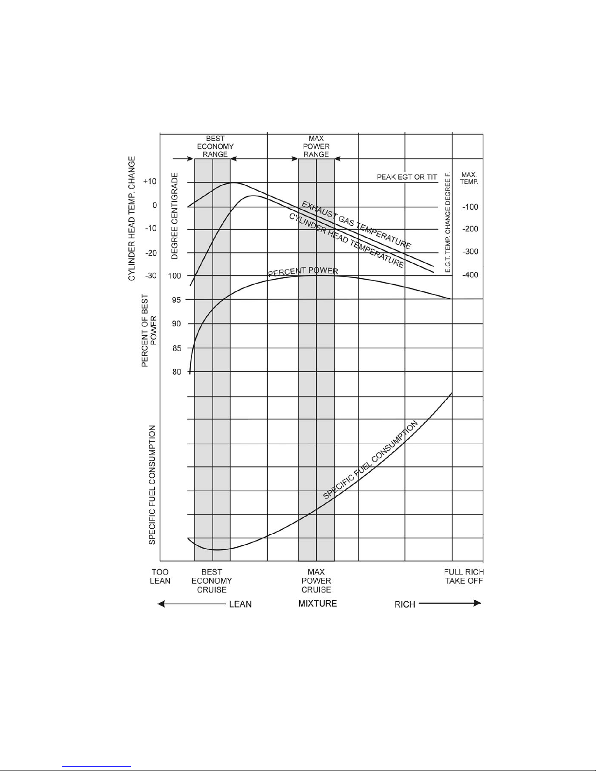
LYCOMING OPERATOR’S MANUAL SECTION 3
O-360 AND ASSOCIATED MODELS OPERATING INSTRUCTIONS
Figure 3-1. Representative Effect of Fuel/Air Ratio on Cylinder Head
Temperature, Power and Specific Fuel Consumption at Constant RPM and
Manifold Pressure in Cruise Range Operation
3-7
Page 45

SECTION 3 LYCOMING OPERATOR’S MANUAL
OPERATING INSTRUCTIONS O-360 AND ASSOCIATED MODELS
(b) Deduct 125°F from this temperature and thus establish the temperature reference point for use
when operating at maximum power mixture.
(c) Return mixture control to full rich and adjust the RPM and manifold pressure for desired
performance cruise operation.
(d) Lean out mixture until EGT or TIT is the value established in step (b). This sets the mixture
at best power.
2. LEANING TO FLOWMETER.
Lean to applicable fuel-flow tables or lean to indicator marked for correct fuel flow for each power
setting.
3. LEANING WITH MANUAL MIXTURE CONTROL. (Economy cruise, 75% power or less, without
flowmeter or EGT gauge.)
a. Carbureted Engines.
(1) Slowly move mixture control from “Full Rich” position toward lean position.
(2) Continue leaning until engine roughness is noted.
(3) Enrich until engine runs smoothly and power is regained.
b. Fuel Injected Engines.
(1) Slowly move mixture control from “Full Rich” position toward lean position.
(2) Continue leaning until slight loss of power is noted (loss of power may or may not be
accompanied by roughness.
(3) Enrich until engine runs smoothly and power is regained.
WARNING
REFER TO THE PILOT’S OPERATING HANDBOOK OR AIRFRAME
MANUFACTURER’S MANUAL FOR ADDITIONAL INSTRUCTIONS ON THE USE OF
CARBURETOR HEAT CONTROL. INSTRUCTIONS FOUND IN EITHER PUBLICATION
SUPERSEDE THE FOLLOWING INFORMATION.
c. Use of Carburetor Heat Control – Under certain moist atmospheric conditions (generally at a relative
humidity of 50% or greater) and at temperatures of 20° to 90°F it is possible for ice to form in the
induction system. Even in summer weather ice may form. This is due to the high air velocity through
the carburetor venturi and the absorption of heat from this air by vaporization of the fuel. The
temperature in the mixture chamber may drop as much as 70°F below the temperature of the
incoming air. If this air contains a large amount of moisture, the cooling process can cause
precipitation in the form of ice. Ice formation generally begins in the vicinity of the butterfly and
may build up to such an extent that a drop in power output could result. In installations equipped
with fixed pitch propellers, a loss of power is reflected by a drop in manifold pressure and RPM. In
installations equipped with constant speed propellers, a loss of power is reflected by a drop in
manifold pressure. If not corrected, this condition may cause complete engine stoppage.
3-8 Revised September 2007
Page 46

LYCOMING OPERATOR’S MANUAL SECTION 3
O-360 AND ASSOCIATED MODELS OPERATING INSTRUCTIONS
To avoid this, all installations are equipped with a system for preheating the incoming air supply to
the carburetor. In this way sufficient heat is added to replace the heat loss of vaporization of fuel, and
the mixing chamber temperature cannot drop to the freezing point of water (32°F). The air preheater is
a tube or jacket through which the exhaust pipe from one or more cylinders is passed, and the air
flowing over these surfaces is raised to the required temperature before entering the carburetor.
Consistently high temperatures are to be avoided because of a loss in power and a decided variation of
mixture. High charge temperatures also favor detonation and preignition, both of which are to be
avoided if normal service life is to be expected from the engine. The following outline is the proper
method of utilizing the carburetor heat control.
(1) Ground Operation – Use of the carburetor air heat on the ground must be held to an absolute
minimum. On some installations the air does not pass through the air filter, and dirt and foreign
substances can be taken into the engine with the resultant cylinder and piston ring wear. Only use
carburetor air heat on the ground to make certain it is functioning properly.
(2) Take-Off – Set the carburetor heat in full cold position. For take-off and full throttle operation the
possibility of expansion or throttle icing at wide throttle openings is very remote.
(3) Climbing – When climbing at part throttle power settings of 80% or above, set the carburetor heat
control in the full cold position; however, if it is necessary to use carburetor heat to prevent icing
it is possible for engine roughness to occur due to the over-rich fuel/air mixture produced by the
additional carburetor heat. When this happens, lean the mixture with the mixture control only
enough to produce smooth engine operation. Do not continue to use carburetor heat after flight is
out of icing conditions, and return mixture to full rich when carburetor heat is removed.
(4) Flight Operation – During normal flight, leave the carburetor air heat control in the full cold
position. On damp, cloudy, foggy or hazy days, regardless of the outside air temperature, be alert
for loss of power. This will be evidenced by an unaccountable loss in manifold pressure or RPM
or both, depending on whether a constant speed or fixed pitch propeller is installed on the
aircraft. If this happens, apply full carburetor air heat and open the throttle to limiting manifold
pressure and RPM. This will result in a slight additional drop in manifold pressure, which is
normal, and this drop will be regained as the ice is melted out of the induction system. When ice
has been melted from the induction system, return the carburetor heat control to the full cold
position. In those aircraft equipped with a carburetor air temperature gauge, partial heat may be
used to keep the mixture temperature above the freezing point of water (32°F).
WARNING
CAUTION MUST BE EXERCISED WHEN OPERATING WITH PARTIAL HEAT ON
AIRCRAFT THAT DO NOT HAVE A CARBURETOR AIR TEMPERATURE GAUGE. USE
EITHER FULL HEAT OR NO HEAT IN AIRCRAFT THAT ARE NOT EQUIPPED WITH A
CARBURETOR AIR TEMPERATURE GAUGE.
(5) Landing Approach – In making a landing approach, the carburetor heat is generally in the “Full
Cold” position. However, if icing conditions are suspected, apply “Full Heat”. In the case that
full power needs to be applied under these conditions, as for an aborted landing, return the
carburetor heat to “Full Cold” after full power application.
Revised September 2007 3-9
Page 47

SECTION 3 LYCOMING OPERATOR’S MANUAL
OPERATING INSTRUCTIONS O-360 AND ASSOCIATED MODELS
8. ENGINE FLIGHT CHART.
FUEL AND OIL
*Aviation Grade Fuel
Model Series Minimum Grade
O-360-B, -D 80/87
O-360-A1P, -C1F, -C4F; HO-360-C1A 91/96
O-360-C, -F; HO-360-A, -B; IO-360-B, -E; HIO-360-B 91/96 or 100/130
O-360-J2A 91/96 or 100/100LL
IO-360-L2A, -M1A, -M1B 91/96 or 100LL
HIO-360-G1A 91/96 or 100LL
O-360-A, -C1G, -C4P, -A1H6; TIO-360-C1A6D 100/100LL
IO-360-B1G6, -C1G6, -J, -K2A, -A1D6D, -A3B6, -A3D6D;
HIO-360-A1B 100/100LL
AIO-360-A, -B; IO-360-A, -C, -D, -F 100/130
HIO-360-A, -C, -D, -E, -F 100/130
TIO-360-A 100/130
NOTE
Aviation grade 100LL fuels in which the lead content is limited to 2 c.c. per gal. are
approved for continuous use in the above listed engines.
* - Refer to latest revision of Service Instruction No. 1070.
FUEL PRESSURE, PSI
Model Max. Desired Min.
O-360 Series (Except -A1C, -C2B,
-C2D); HO-360-A, -C Series
Inlet to carburetor 8.0 3.0 0.5
O-360-A1C, -C2B, -C1D;
HO-360-B Series
Inlet to carburetor 18 13 9.0
HIO-360-A1B
Inlet to fuel pump 30 ----- -2
IO-360 Series (Except -B1A, -F1A);
AIO-360 Series, HIO-360 Series
(Except -A1B)
Inlet to fuel pump 35 ----- -2
IO-360-F1A
Inlet to fuel pump 35 ----- -2
IO-360 Series (Except -B1A),
AIO-360 Series; HIO-360 Series
Inlet to fuel injector 45 14
IO-360-B1A
Inlet to fuel injector 2 -2
3-10
Page 48

LYCOMING OPERATOR’S MANUAL SECTION 3
O-360 AND ASSOCIATED MODELS OPERATING INSTRUCTIONS
FUEL PRESSURE, PSI (CONT.) –
Model Max. Desired Max.
HIO-360-E, -F Series
Inlet to fuel pump 55 -2
Inlet to fuel injector 55 27
TIO-360-A Series
Inlet to fuel pump 50 -2
Inlet to fuel injector 45 20
TIO-360-C1A6D
Inlet to fuel pump 65 -2
Inlet to fuel injector 65 22
OIL – (All Models) –
*Recommended Grade Oil
MIL-L-22851
Average MIL-L-6082B Ashless Dispersant
Ambient Air Grades Grades
All Temperatures --------- SAE 15W-50 or 20W-50
Above 80°F SAE 60 SAE60
Above 60°F SAE 50 SAE 40 or SAE 50
30° to 90°F SAE 40 SAE 40
0° to 70°F SAE 30 SAE 40, 30 or 20W40
Below 10°F SAE 20 SAE 30 or 20W30
* - Refer to latest revision of Service Instruction No. 1014.
OIL SUMP CAPACITY
All Models (Except AIO-360 Series, O-360-J2A) ................................................8 U.S. Quarts
Minimum Safe Quantity in Sump
(Except – IO-360-M1A, -M1B; HIO-360-G1A)................................................2 U.S. Quarts
IO-360-M1A, -M1B; HIO-360-G1A..................................................................4 U.S. Quarts
AIO-360 Series ...........................................................................................................Dry Sump
O-360-J2A..............................................................................................................6 U.S. Quarts
OPERATING CONDITIONS
Average *Oil Inlet Temperature
Ambient Air Desired Maximum
Above 80°F 180°F (82°C) 245°F (118°C)
Above 60°F 180°F (82°C) 245°F (118°C)
30° to 90°F 180°F (82°C) 245°F (118°C)
0° to 70°F 170°F (77°C) 245°F (118°C)
Below 10°F 160°F (71°C) 245°F (118°C)
* - Engine oil temperature should not be below 140°F (60°C) during continuous operation.
Revised September 2007 3-11
Page 49

SECTION 3 LYCOMING OPERATOR’S MANUAL
OPERATING INSTRUCTIONS O-360 AND ASSOCIATED MODELS
OPERATING CONDITIONS (CONT.)
Oil Pressure, psi (Rear) Maximum Minimum Idling
Normal Operation, All Models
(Except Below) 95 55 25
TIO-360-C1A6D 95 50 25
Oil Pressure, psi (Front)
O-360-A4N, -F1A6 90 50 20
Start, Warm-up, Taxi, and Take-off
(All Models) 115
Fuel Max. *Max.
Cons. Oil Cons. Cyl. Head
Operation RPM HP Gal/Hr. Qts./Hr. Temp.
O-360-A, -C** Series
Normal Rated 2700 180 ----- .80 500°F (260°C)
Performance Cruise
(75% Rated) 2450 135 10.5 .45 500°F (260°C)
Economy Cruise
(65% Rated) 2350 117 9.5 .39 500°F (260°C)
O-360-B, -D Series
Normal Rated 2700 168 ----- .75 500°F (260°C)
Performance Cruise
(75% Rated) 2450 126 11.6 .42 500°F (260°C)
Economy Cruise
(65% Rated) 2350 109 9.0 .37 500°F (260°C)
O-360-A1P, -A4D, -A4P, -C4P, -F, -G Series
Normal Rated 2700 180 ----- .80 500°F (260°C)
Performance Cruise
(75% Rated) 2450 135 9.7 .45 500°F (260°C)
Economy Cruise
(65% Rated) 2350 117 8.3 .39 500°F (260°C)
* - At Bayonet Location For maximum service life of the engine maintain cylinder head temperature
between 150°F and 400°F during continuous operation.
** - O-360-C2D Only Take-off rating 180 HP at 2900 RPM, 28 in. Hg.
3-12
Page 50

LYCOMING OPERATOR’S MANUAL SECTION 3
O-360 AND ASSOCIATED MODELS OPERATING INSTRUCTIONS
OPERATING CONDITIONS (CONT.)
Fuel Max. *Max.
Cons. Oil Cons. Cyl. Head
Operation RPM HP Gal./Hr. Qts./Hr. Temp.
O-360-J2A
Normal Rated 2400/2700 145 ----- .50 500°F (260°C)
Performance Cruise
(75% Rated) 1800/2025 109 9.3 .36 500°F (260°C)
Economy Cruise
(65% Rated) 1560/1755 94 6.8 .31 500°F (260°C)
HO-360-A, -C Series; HIO-360-G1A
Normal Rated 2700 180 ----- .80 500°F (260°C)
Performance Cruise
(75% Rated) 2450 135 9.7 .45 500°F (260°C)
Economy Cruise
(65% Rated) 2350 117 9.0 .39 500°F (260°C)
HO-360-B Series
Normal Rated 2900 180 ----- .80 500°F (260°C)
Performance Cruise
(75% Rated) 2700 135 10.5 .45 500°F (260°C)
Economy Cruise
(65% Rated) 2700 117 9.0 .39 500°F (260°C)
IO-360-A, -C, -D, -J, -K; AIO-360 Series
Normal Rated 2700 200 ----- .89 500°F (260°C)
Performance Cruise
(75% Rated) 2450 150 12.3 .50 500°F (260°C)
Economy Cruise
(65% Rated) 2350 130 9.5 .44 500°F (260°C)
IO-360-B, -E, -F Series (Except -B1C); IO-360-M1A**, -M1B**
Normal Rated 2700 180 ----- .80 500°F (260°C)
Performance Cruise
(75% Rated) 2450 135 11.0 .45 500°F (260°C)
Economy Cruise
(65% Rated) 2350 117 8.5 .39 500°F (260°C)
* - At Bayonet Location For maximum service life of the engine maintain cylinder head temperature
between 150°F and 400°F during continuous operation.
** - This engine has an alternate rating of 160 HP at 2400 RPM.
3-13
Page 51

SECTION 3 LYCOMING OPERATOR’S MANUAL
OPERATING INSTRUCTIONS O-360 AND ASSOCIATED MODELS
OPERATING CONDITIONS (CONT.)
Fuel Max. *Max.
Cons. Oil Cons. Cyl. Head
Operation RPM HP Gal./Hr. Qts./Hr. Temp.
IO-360-B1C
Normal Rated 2700 177 ----- .79 500°F (260°C)
Performance Cruise
(75% Rated) 2450 133 11.0 .45 500°F (260°C)
Economy Cruise
(65% Rated) 2350 115 8.5 .39 500°F (260°C)
IO-360-L2A
Normal Rated 2400 160 ----- .52 500°F (260°C)
Performance Cruise
(75% Rated) 2180 120 8.8 .39 500°F (260°C)
Economy Cruise
(65% Rated) 2080 104 7.6 .34 500°F (260°C)
HIO-360-A Series
Normal Rated 2900 180 ----- .80 500°F (260°C)
Performance Cruise
(75% Rated) 2700 135 11.0 .45 500°F (260°C)
Economy Cruise
(65% Rated) 2700 117 9.5 .39 500°F (260°C)
HIO-360-B Series
Normal Rated 2900 180 ----- .80 500°F (260°C)
Performance Cruise
(75% Rated) 2700 135 12.0 .45 500°F (260°C)
Economy Cruise
(65% Rated) 2700 117 10.0 .39 500°F (260°C)
HIO-360-C Series
Normal Rated 2900 205 ----- .91 500°F (260°C)
Performance Cruise
(75% Rated) 2700 154 12.5 .52 500°F (260°C)
Economy Cruise
(65% Rated) 2700 133 10.5 .45 500°F (260°C)
* - At Bayonet Location For maximum service life of the engine maintain cylinder head temperature
between 150°F and 400°F during continuous operation.
- At 26 in. Hg. manifold pressure.
3-14
Page 52

LYCOMING OPERATOR’S MANUAL SECTION 3
O-360 AND ASSOCIATED MODELS OPERATING INSTRUCTIONS
OPERATING CONDITIONS (CONT.)
Fuel Max. *Max.
Cons. Oil Cons. Cyl. Head
Operation RPM HP Gal./Hr. Qts./Hr. Temp.
HIO-360-D Series
Normal Rated 3200 190 ----- .85 500°F (260°C)
Performance Cruise
(75% Rated) 3200 142 12.0 .48 500°F (260°C)
Economy Cruise
(65% Rated) 3200 123 10.0 .41 500°F (260°C)
HIO-360-E Series
Normal Rated 2900 190 ----- .85 500°F (260°C)
Performance Cruise
(75% Rated) 2700 142 11.8 .47 500°F (260°C)
Economy Cruise
(65% Rated) 2700 123 10.0 .41 500°F (260°C)
HIO-360-F Series
Normal Rated 3050 190 ----- .84 500°F (260°C)
Performance Cruise
(75% Rated) 2700 142 11.8 .47 500°F (260°C)
Economy Cruise
(65% Rated) 2700 123 10.0 .46 500°F (260°C)
TIO-360-A Series**
Normal Rated 2700 200 ----- .89 500°F (260°C)
Performance Cruise
(75% Rated) 2450 150 14.0 .50 500°F (260°C)
Economy Cruise
(65% Rated) 2350 130 10.2 .44 500°F (260°C)
TIO-360-C Series**
Normal Rated 2575 210 ----- .70 500°F (260°C)
Performance Cruise
(75% Rated) 2400 157.5 13.2 .53 500°F (260°C)
Economy Cruise
(65% Rated) 2200 136.5 10.2 .46 500°F (260°C)
* - At Bayonet Location For maximum service life of the engine maintain cylinder head temperature
between 150°F and 400°F during continuous operation.
** - MAXIMUM TURBINE INLET TEMPERATURE 1650°F (898.8°C).
3-15
Page 53

SECTION 3 LYCOMING OPERATOR’S MANUAL
OPERATING INSTRUCTIONS O-360 AND ASSOCIATED MODELS
9. SHUT DOWN PROCEDURE.
a. Fixed Wing.
(1) Set propeller governor control for minimum blade angle when applicable.
(2) Idle until there is a decided drop in cylinder head temperature.
(3) Move mixture control to Idle Cut-Off.
(4) When engine stops, turn off switches.
b. Helicopters.
(1) Idle as directed in the airframe manufacturers handbook, until there is a decided drop in cylinder
head temperature.
(2) Move mixture control to Idle Cut-Off.
(3) When engine stops, turn off switches.
3-16
Page 54
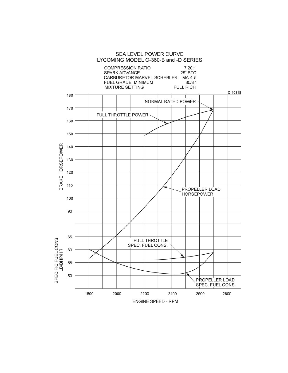
LYCOMING OPERATOR’S MANUAL SECTION 3
O-360 AND ASSOCIATED MODELS OPERATING INSTRUCTIONS
Figure 3-2. Power Curve O-360-B, -D Series
3-17
Page 55
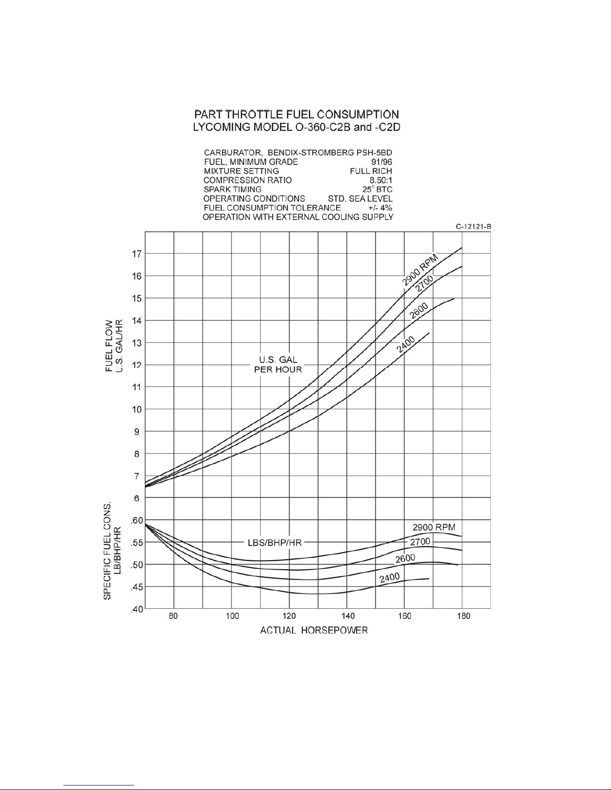
SECTION 3 LYCOMING OPERATOR’S MANUAL
OPERATING INSTRUCTIONS O-360 AND ASSOCIATED MODELS
Figure 3-3. Part Throttle Fuel Consumption
O-360-C2B, -C2D
3-18
Page 56

LYCOMING OPERATOR’S MANUAL SECTION 3
O-360 AND ASSOCIATED MODELS OPERATING INSTRUCTIONS
Figure 3-4. Part Throttle Fuel Consumption
HO-360-B Series
3-19
Page 57

SECTION 3 LYCOMING OPERATOR’S MANUAL
OPERATING INSTRUCTIONS O-360 AND ASSOCIATED MODELS
Figure 3-5. Part Throttle Fuel Consumption
IO-360-A, -C, -D, -J, -K; AIO-360 Series
3-20
Page 58

LYCOMING OPERATORS MANUAL SECTION 3
O-360 AND ASSOCIATED MODELS OPERATING INSTRUCTIONS
Figure 3-6. Part Throttle Fuel Consumption
IO-360-B, -E, -F, , -M1B Series (Excepting IO-360-B1A, -B1C); HIO-360-G1A
- For information pertaining to engine model (L)IO-360-M1A, refer to Operation and Installation Manual
P/N 60297-36.
Revised March 2009 3-21
Page 59

SECTION 3 LYCOMING OPERATOR’S MANUAL
OPERATING INSTRUCTIONS O-360 AND ASSOCIATED MODELS
Figure 3-7. Part Throttle Fuel Consumption
IO-360-B1A
3-22
Page 60

LYCOMING OPERATOR’S MANUAL SECTION 3
O-360 AND ASSOCIATED MODELS OPERATING INSTRUCTIONS
Figure 3-8. Part Throttle Fuel Consumption
IO-360-B1C
3-23
Page 61

SECTION 3 LYCOMING OPERATOR’S MANUAL
OPERATING INSTRUCTIONS O-360 AND ASSOCIATED MODELS
Figure 3-9. Part Throttle Fuel Consumption
IO-360-L2A
3-24
Page 62
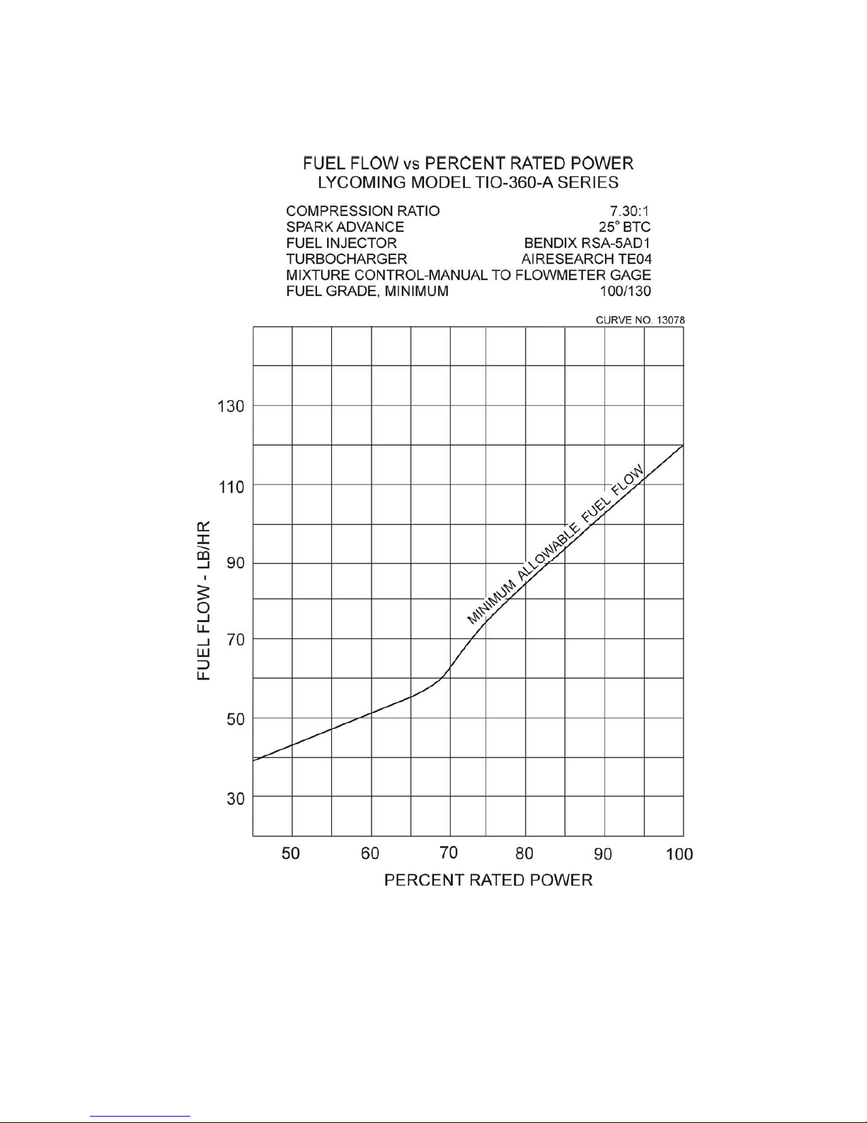
LYCOMING OPERATOR’S MANUAL SECTION 3
O-360 AND ASSOCIATED MODELS OPERATING INSTRUCTIONS
Figure 3-10. Fuel Flow vs Percent Rated Power
TIO-360-A Series
3-25
Page 63

SECTION 3 LYCOMING OPERATOR’S MANUAL
OPERATING INSTRUCTIONS O-360 AND ASSOCIATED MODELS
Figure 3-11. Fuel Flow vs Percent Rated Power
HIO-360-D
3-26
Page 64
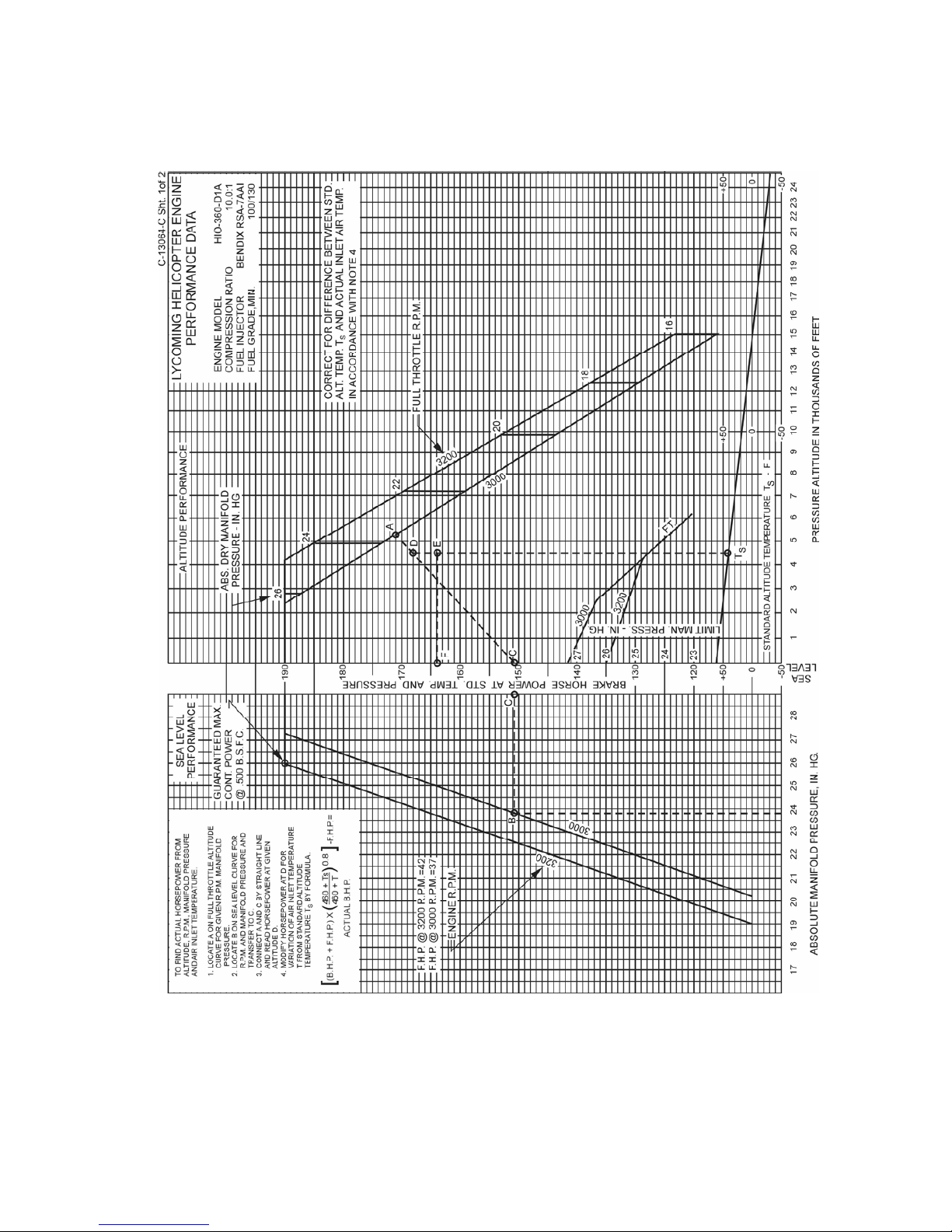
LYCOMING OPERATOR’S MANUAL SECTION 3
O-360 AND ASSOCIATED MODELS OPERATING INSTRUCTIONS
Figure 3-12. Sea Level and Altitude Performance
HIO-360-D (Sheet 1 of 2)
3-27
Page 65
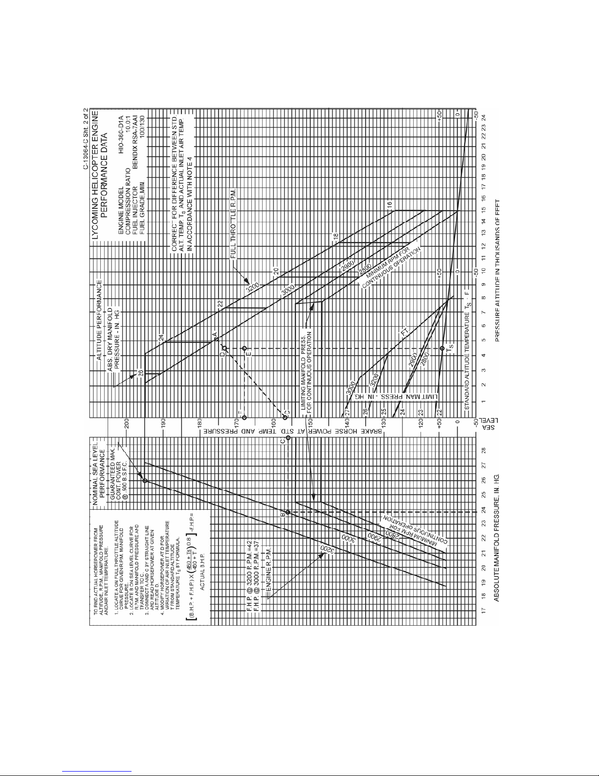
SECTION 3 LYCOMING OPERATOR’S MANUAL
OPERATING INSTRUCTIONS O-360 AND ASSOCIATED MODELS
Figure 3-13. Sea Level and Altitude Performance
HIO-360-D (Sheet 2 of 2)
3-28
Page 66

LYCOMING OPERATOR’S MANUAL SECTION 3
O-360 AND ASSOCIATED MODELS OPERATING INSTRUCTIONS
Figure 3-14. Fuel Flow vs Percent Rated Power
HIO-360-A Series
3-29
Page 67

SECTION 3 LYCOMING OPERATOR’S MANUAL
OPERATING INSTRUCTIONS O-360 AND ASSOCIATED MODELS
Figure 3-15. Fuel Flow vs Percent Rated Power
HIO-360-B Series
3-30
Page 68

LYCOMING OPERATOR’S MANUAL SECTION 3
O-360 AND ASSOCIATED MODELS OPERATING INSTRUCTIONS
Figure 3-16. Fuel Flow vs Percent Rated Power
HIO-360-C Series
3-31
Page 69

SECTION 3 LYCOMING OPERATOR’S MANUAL
OPERATING INSTRUCTIONS O-360 AND ASSOCIATED MODELS
Figure 3-17. Sea Level and Altitude Performance
O-360-A, -C (Except those listed for Figure 3-40); HIO-360-A Series
3-32
Page 70
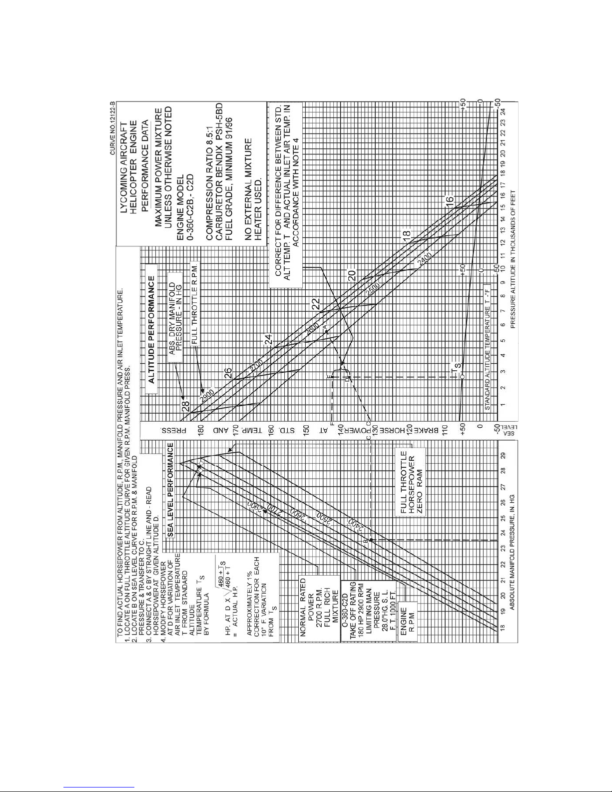
LYCOMING OPERATOR’S MANUAL SECTION 3
O-360 AND ASSOCIATED MODELS OPERATING INSTRUCTIONS
Figure 3-18. Sea Level and Altitude Performance
O-360-C2B, -C2D
3-33
Page 71
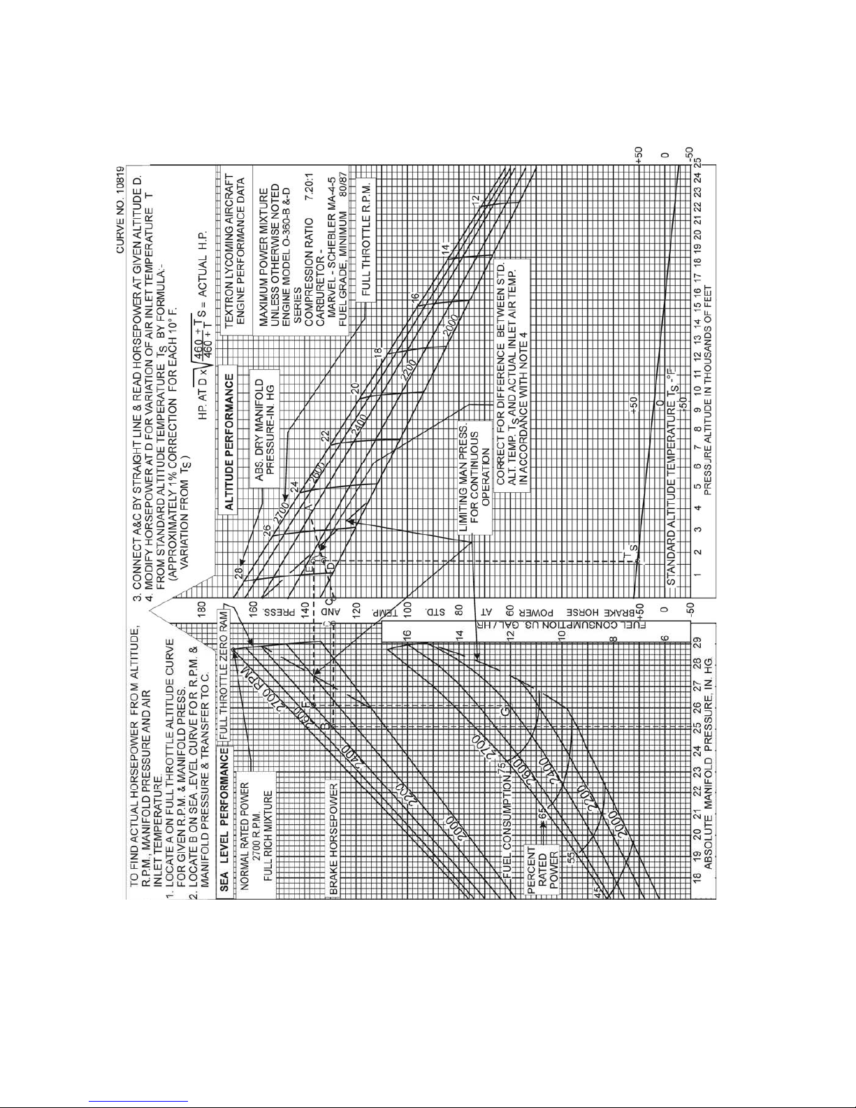
SECTION 3 LYCOMING OPERATOR’S MANUAL
OPERATING INSTRUCTIONS O-360 AND ASSOCIATED MODELS
Figure 3-19. Sea Level and Altitude Performance
O-360-B, -D Series
3-34
Page 72

LYCOMING OPERATOR’S MANUAL SECTION 3
O-360 AND ASSOCIATED MODELS OPERATING INSTRUCTIONS
Figure 3-20. Sea Level and Altitude Performance
HO-360-B Series
3-35
Page 73
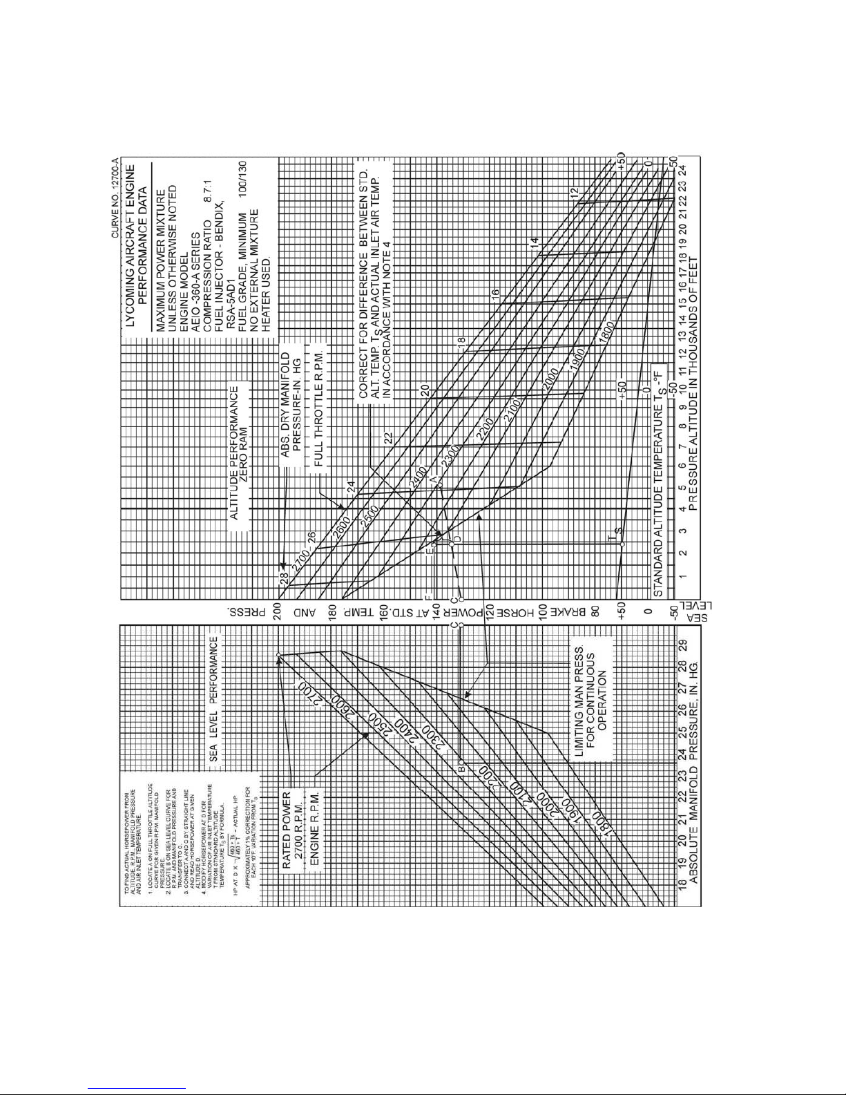
SECTION 3 LYCOMING OPERATOR’S MANUAL
OPERATING INSTRUCTIONS O-360 AND ASSOCIATED MODELS
Figure 3-21. Sea Level and Altitude Performance
IO-360-A, -C, -D, -J, -K; AIO-360 Series
3-36
Page 74
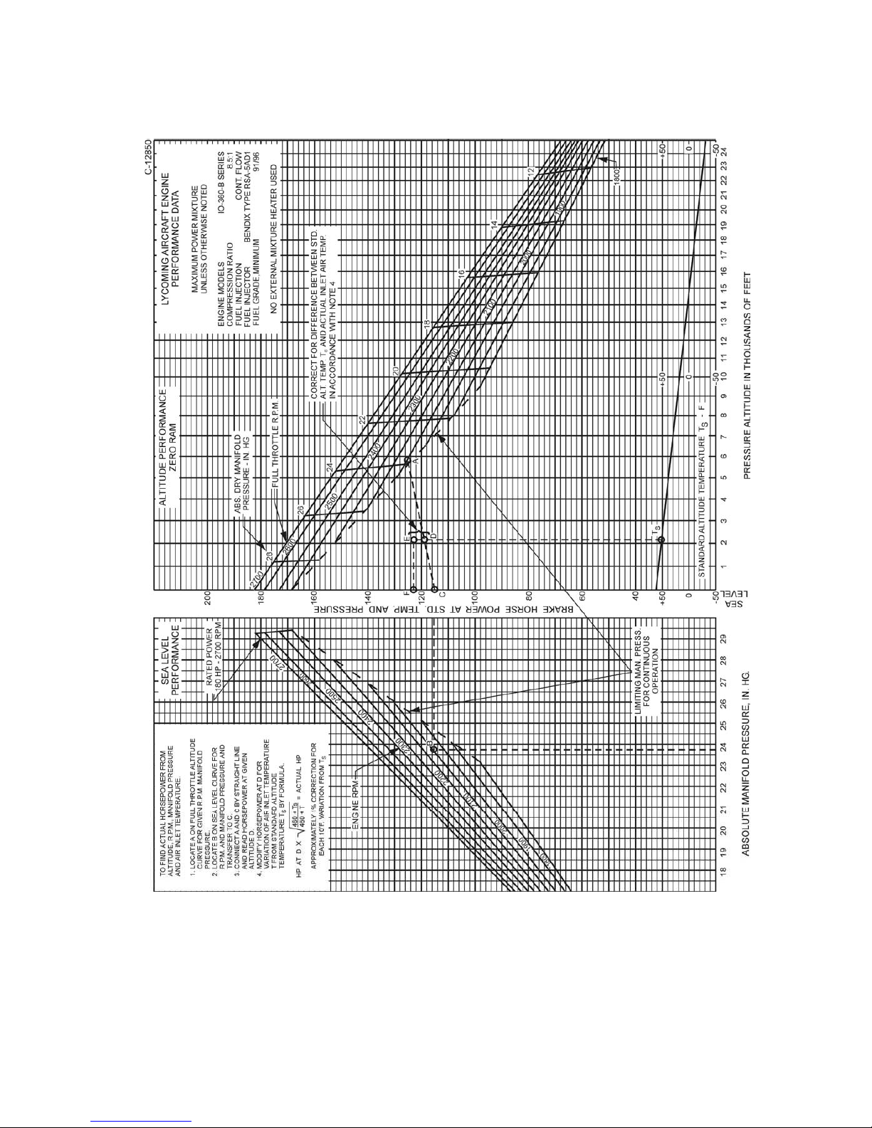
LYCOMING OPERATOR’S MANUAL SECTION 3
O-360 AND ASSOCIATED MODELS OPERATING INSTRUCTIONS
Figure 3-22. Sea Level and Altitude Performance
IO-360-B, -E, -F Series (Excepting IO-360-B1A, -B1C)
HIO-360-G1A
3-37
Page 75
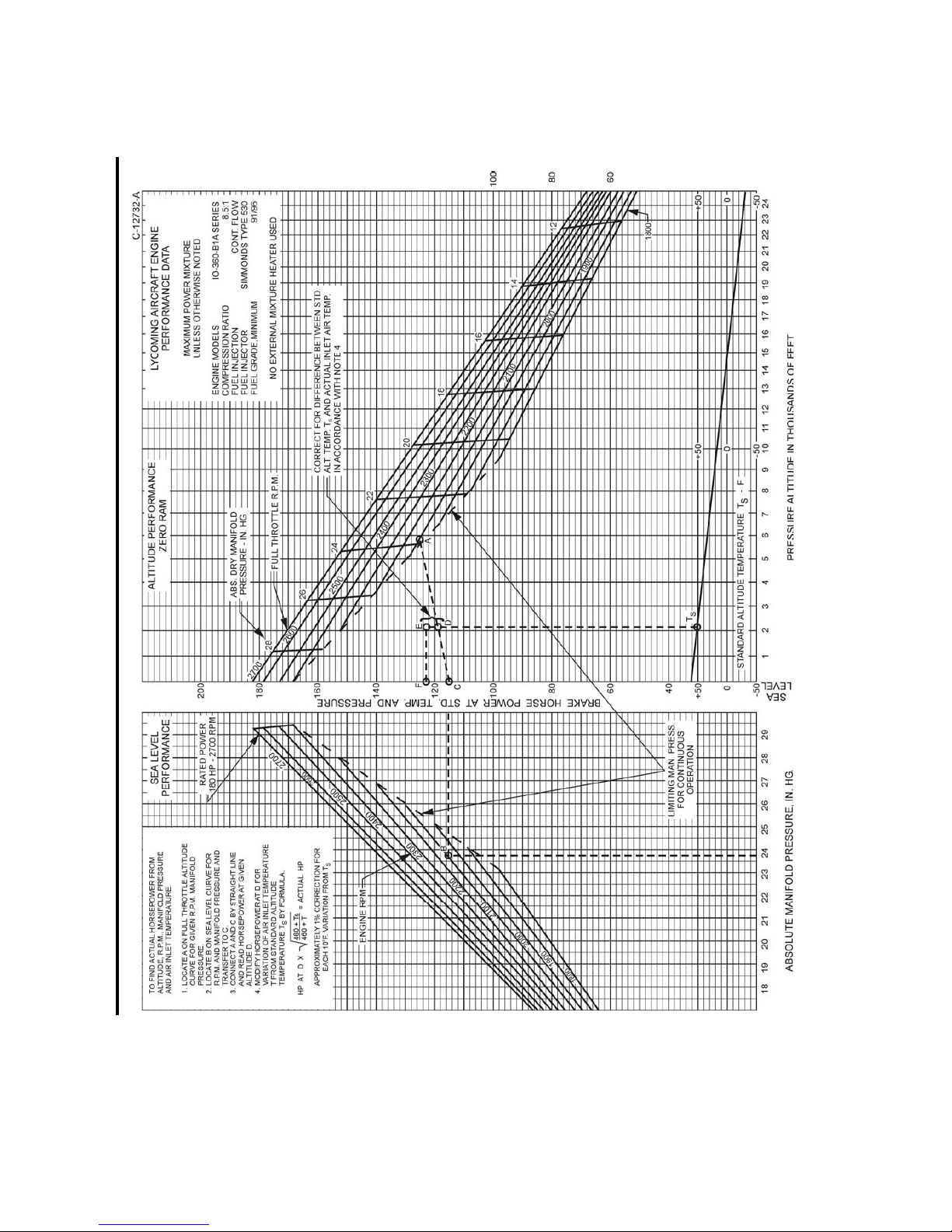
SECTION 3 LYCOMING OPERATOR’S MANUAL
OPERATING INSTRUCTIONS O-360 AND ASSOCIATED MODELS
Figure 3-23. Sea Level and Altitude Performance –
IO-360-B1A
3-38 Revised June 2007
Page 76
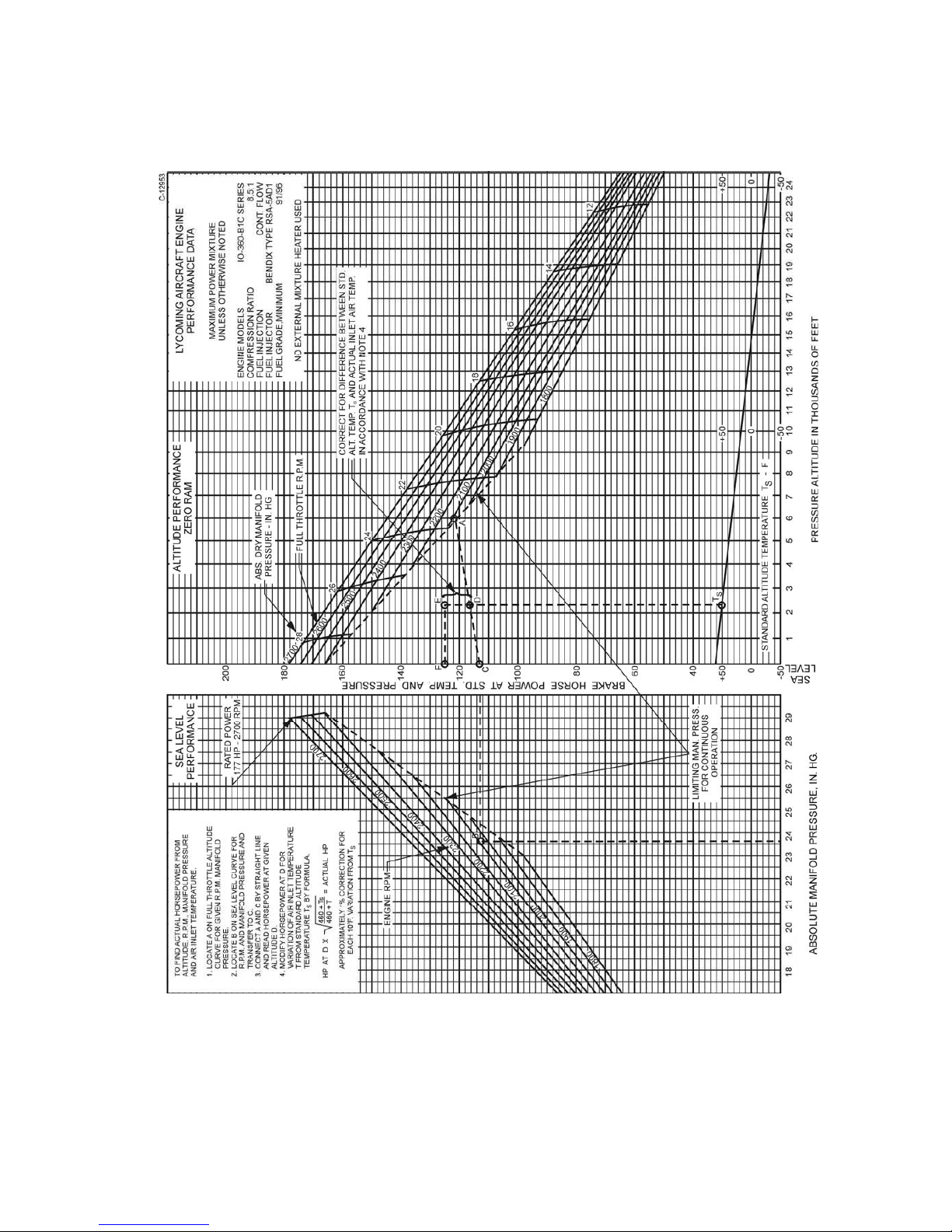
LYCOMING OPERATOR’S MANUAL SECTION 3
O-360 AND ASSOCIATED MODELS OPERATING INSTRUCTIONS
Figure 3-24. Sea Level and Altitude Performance
IO-360-B1C
3-39
Page 77
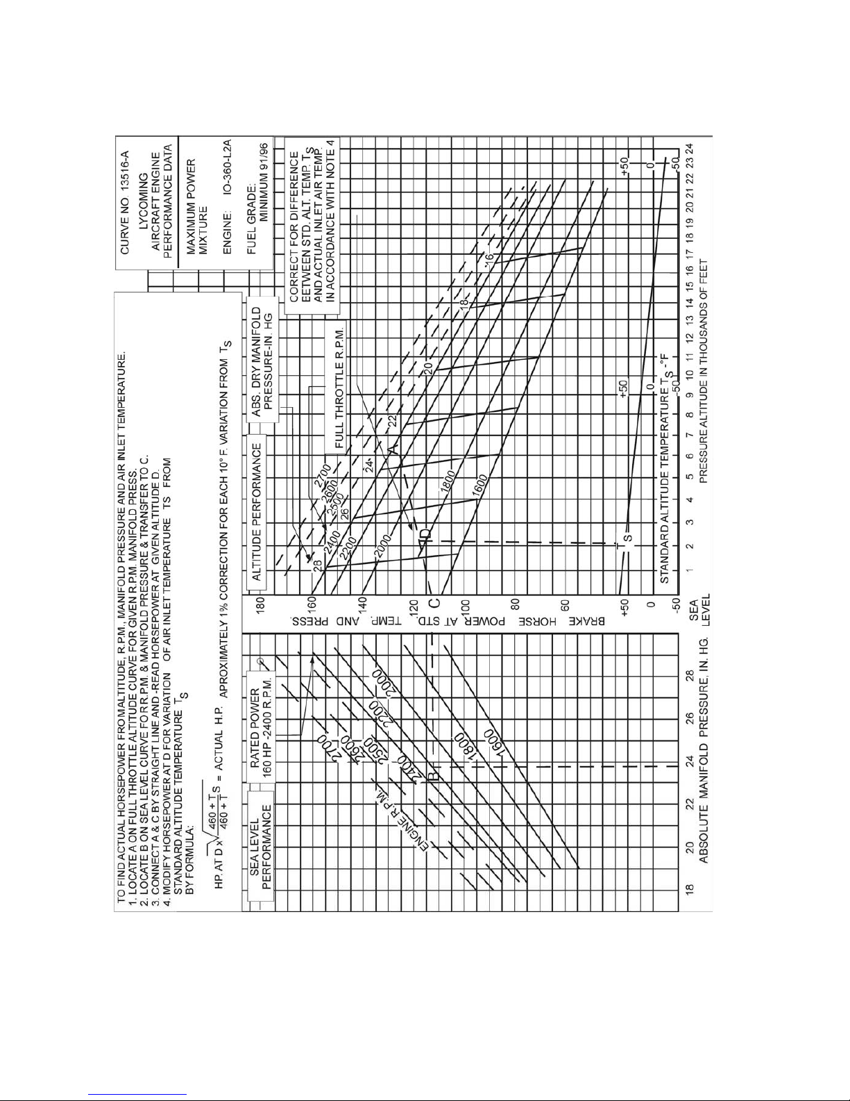
SECTION 3 LYCOMING OPERATOR’S MANUAL
OPERATING INSTRUCTIONS O-360 AND ASSOCIATED MODELS
Figure 3-25. Sea Level and Altitude Performance
IO-360-L2A
3-40
Page 78
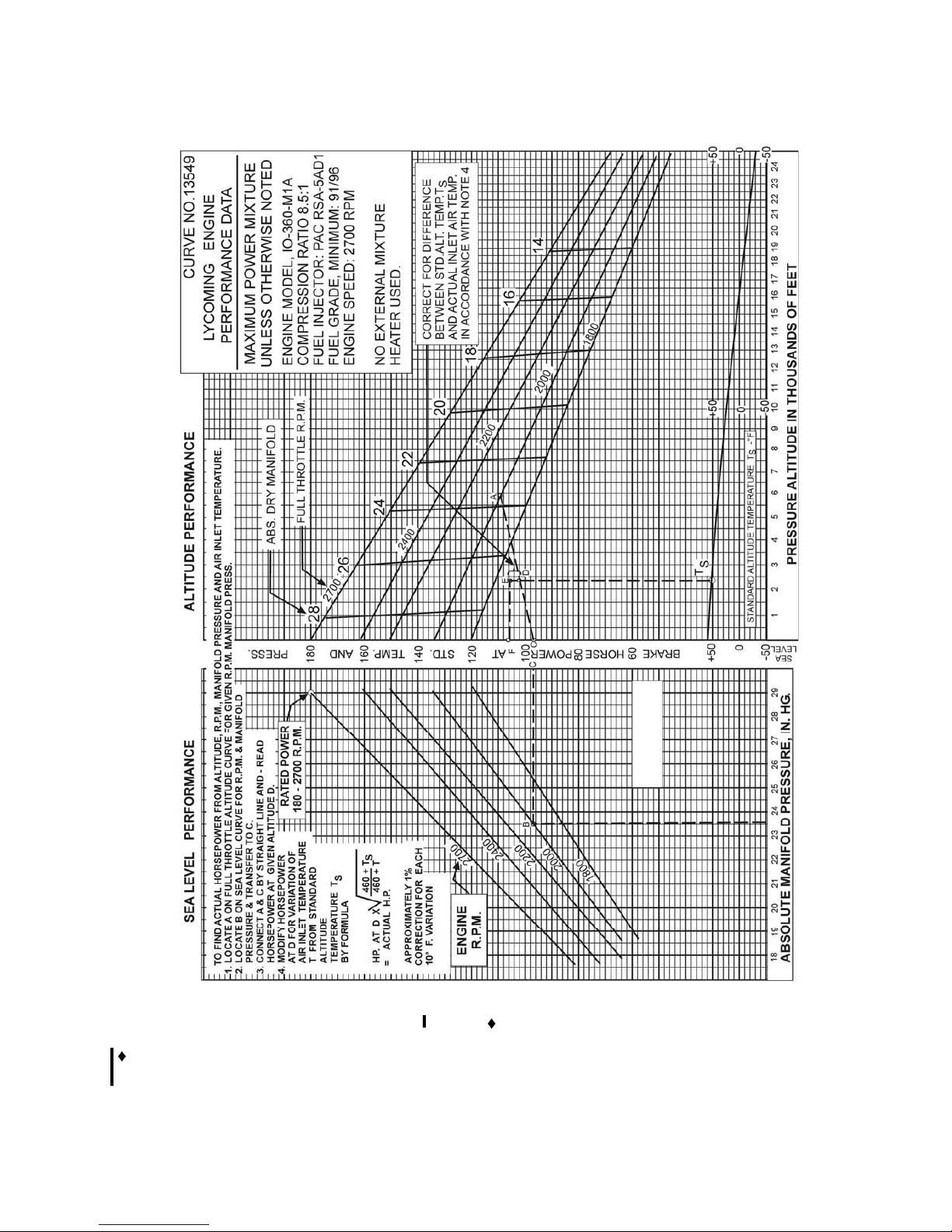
LYCOMING OPERATORS MANUAL SECTION 3
O-360 AND ASSOCIATED MODELS OPERATING INSTRUCTIONS
Figure 3-26. Sea Level and Altitude Performance
IO-360- , -M1B
- For information pertaining to engine model (L)IO-360-M1A, refer to Operation and Installation Manual
P/N 60297-36.
Revised March 2009 3-41
Page 79
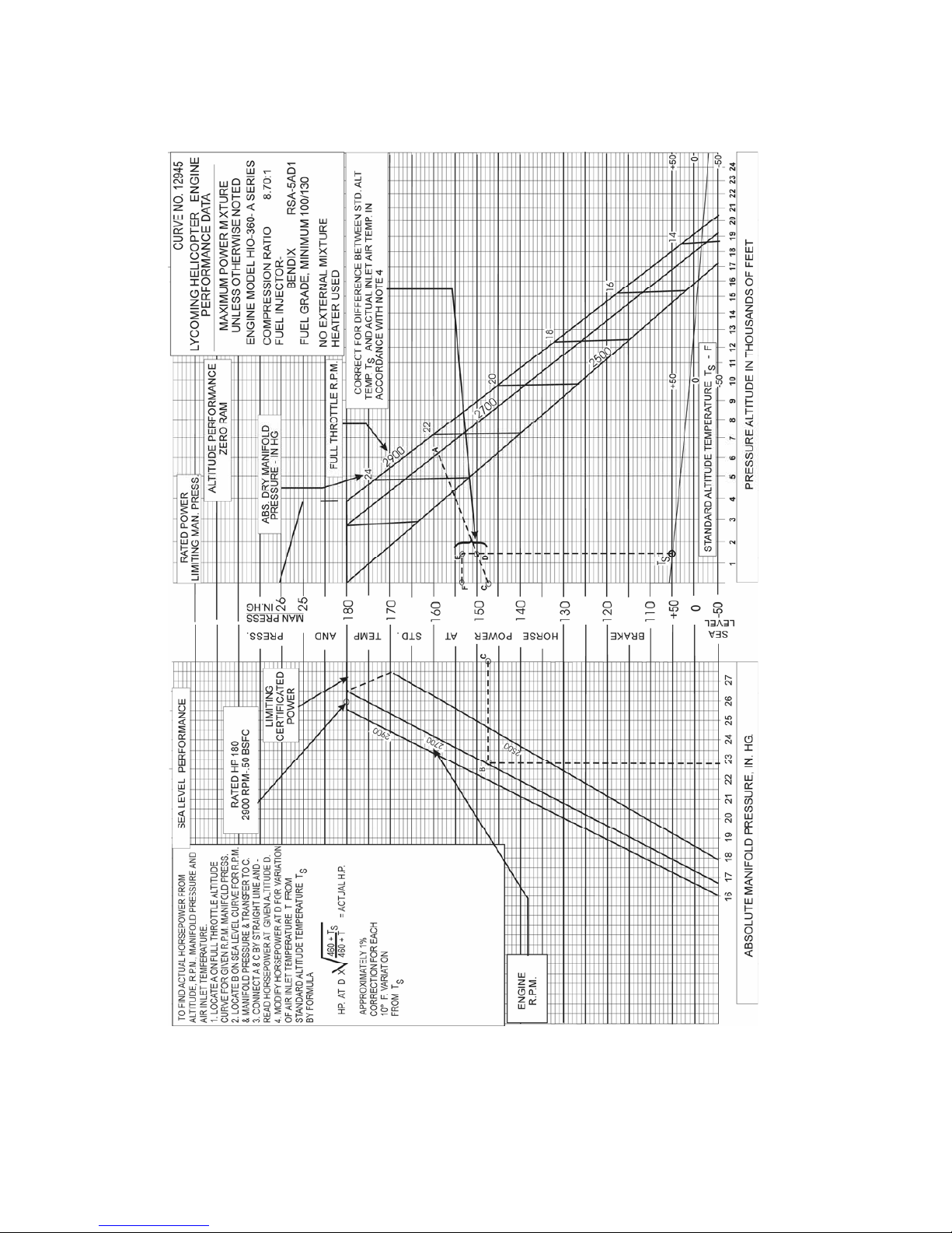
SECTION 3 LYCOMING OPERATOR’S MANUAL
OPERATING INSTRUCTIONS O-360 AND ASSOCIATED MODELS
Figure 3-28. Sea Level and Altitude Performance
HIO-360-A Series
3-42
Page 80
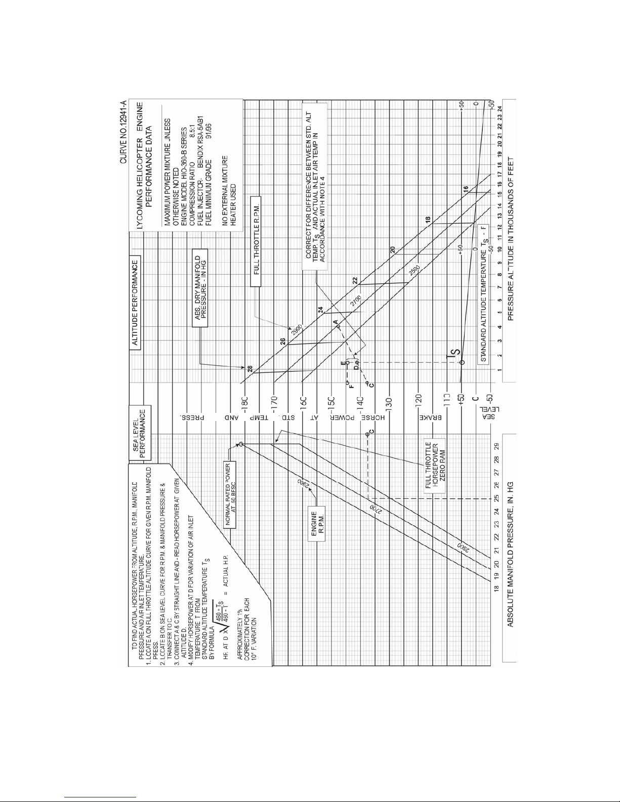
LYCOMING OPERATOR’S MANUAL SECTION 3
O-360 AND ASSOCIATED MODELS OPERATING INSTRUCTIONS
Figure 3-29. Sea Level and Altitude Performance
HIO-360-B Series
3-43
Page 81
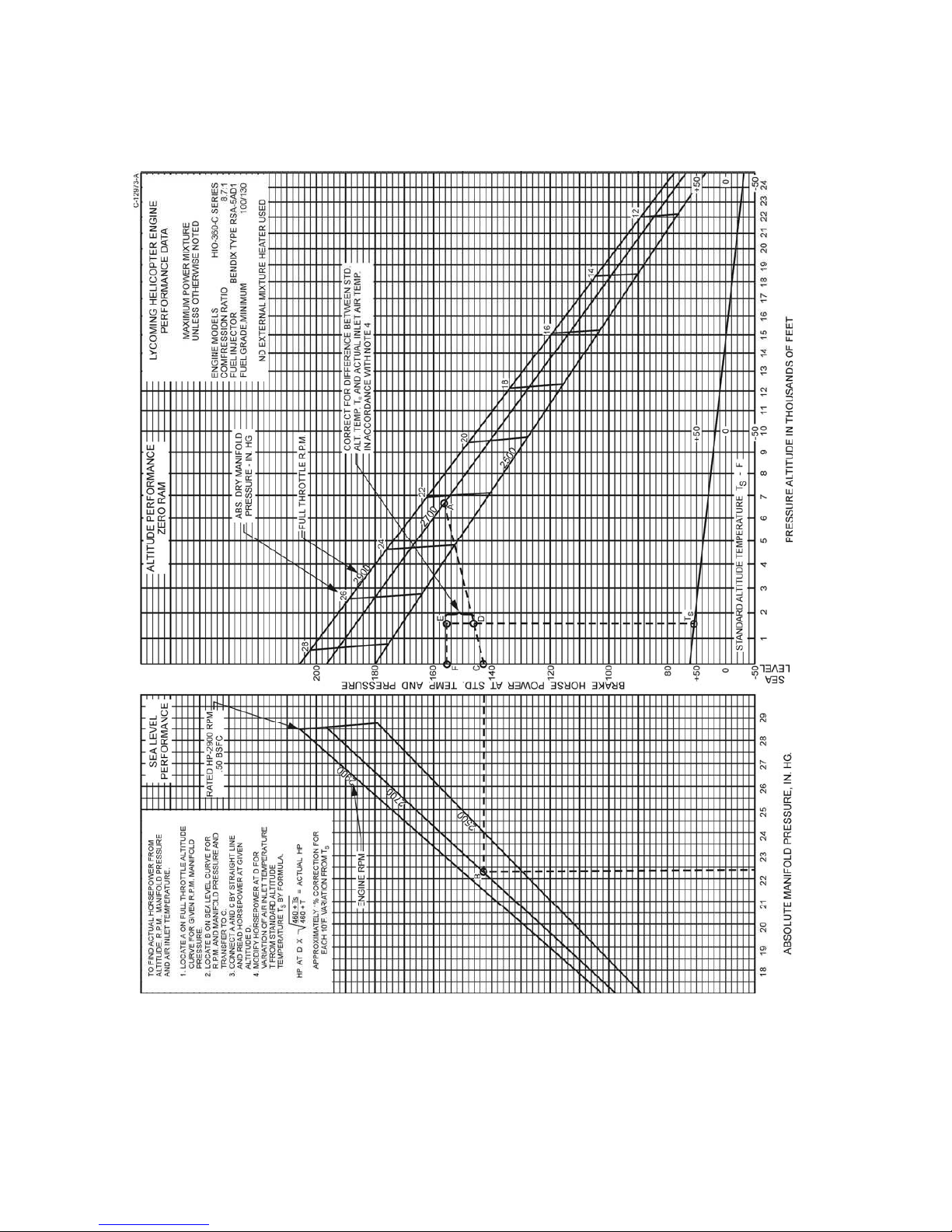
SECTION 3 LYCOMING OPERATOR’S MANUAL
OPERATING INSTRUCTIONS O-360 AND ASSOCIATED MODELS
Figure 3-30. Sea Level and Altitude Performance
HIO-360-C Series
3-44
Page 82
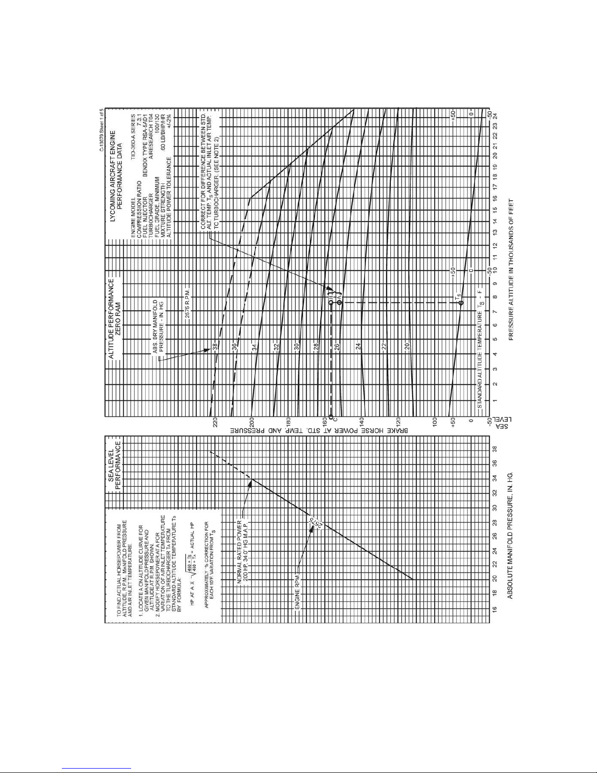
LYCOMING OPERATOR’S MANUAL SECTION 3
O-360 AND ASSOCIATED MODELS OPERATING INSTRUCTIONS
Figure 3-31. Sea Level and Altitude Performance
TIO-360-A Series (Sheet 1 of 5)
3-45
Page 83
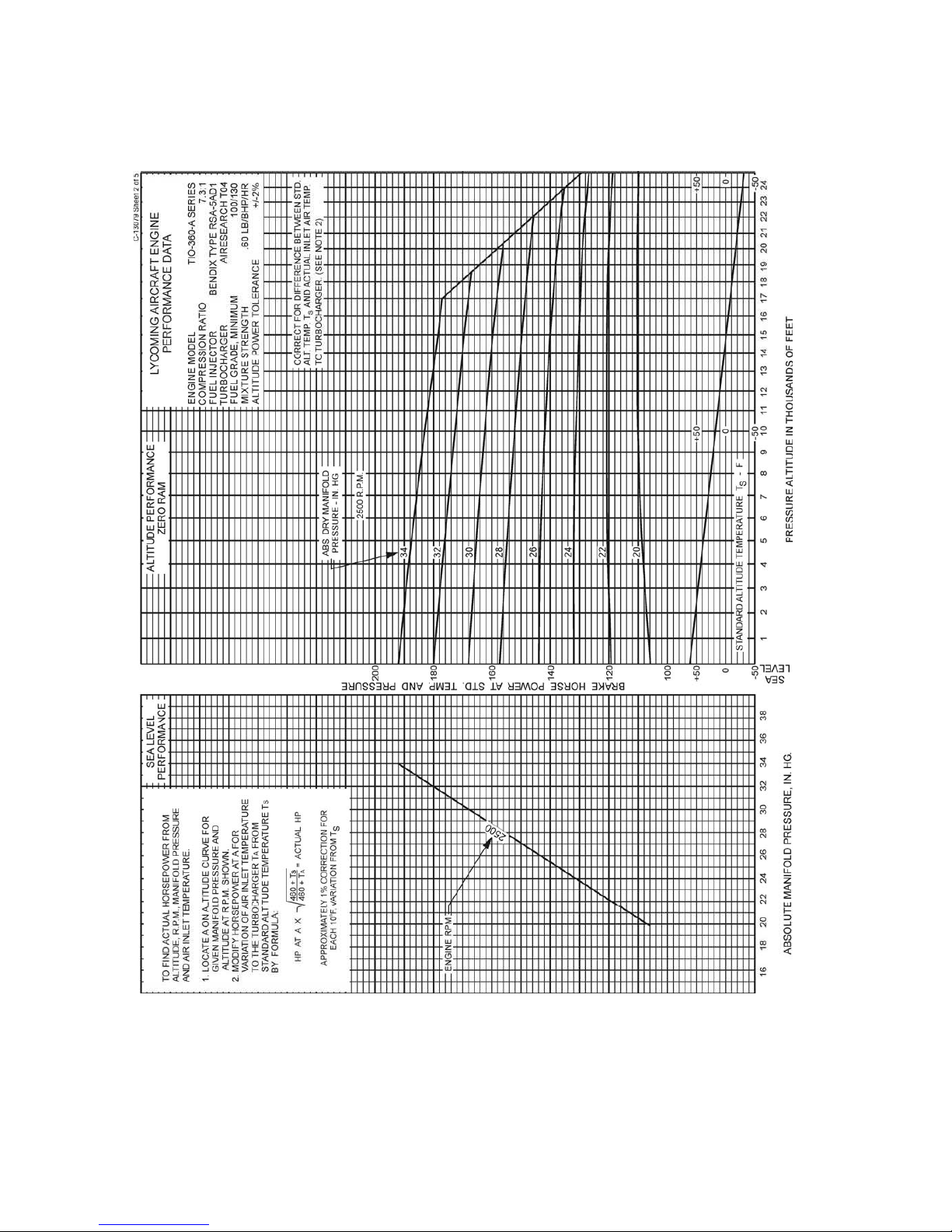
SECTION 3 LYCOMING OPERATOR’S MANUAL
OPERATING INSTRUCTIONS O-360 AND ASSOCIATED MODELS
Figure 3-32. Sea Level and Altitude Performance
TIO-360-A Series (Sheet 2 of 5)
3-46
Page 84
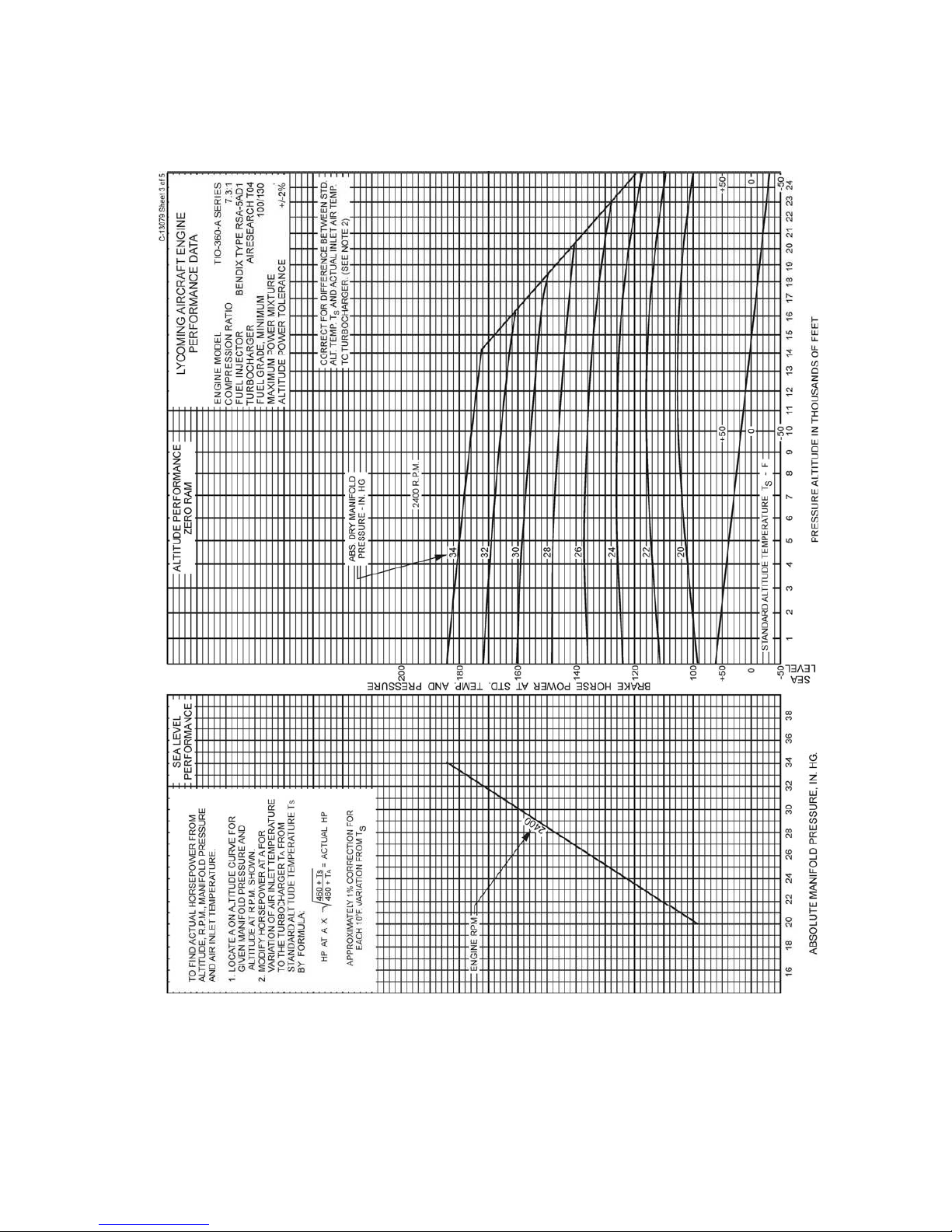
LYCOMING OPERATOR’S MANUAL SECTION 3
O-360 AND ASSOCIATED MODELS OPERATING INSTRUCTIONS
Figure 3-33. Sea Level and Altitude Performance
TIO-360-A Series (Sheet 3 of 5)
3-47
Page 85
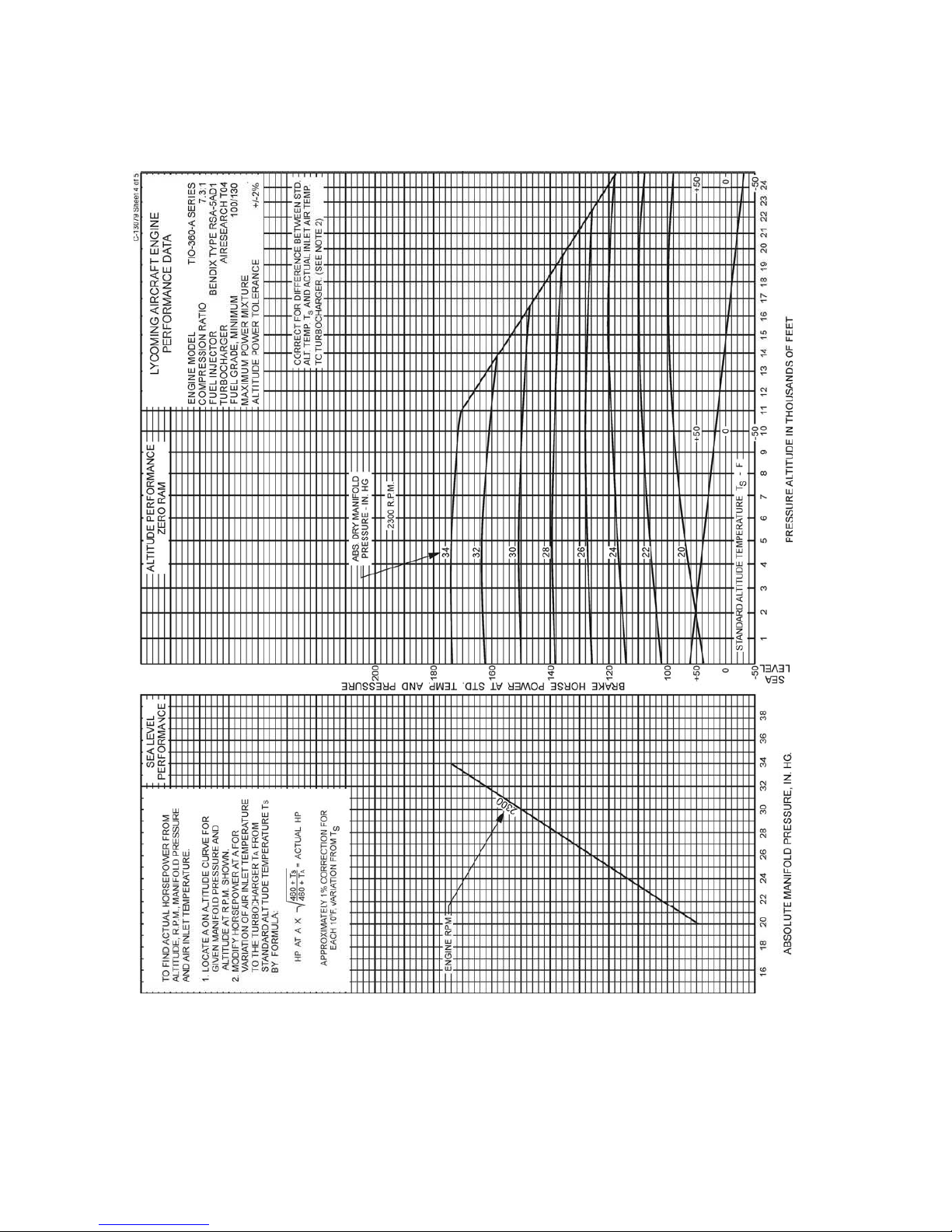
SECTION 3 LYCOMING OPERATOR’S MANUAL
OPERATING INSTRUCTIONS O-360 AND ASSOCIATED MODELS
Figure 3-34. Sea Level and Altitude Performance
TIO-360-A Series (Sheet 4 of 5)
3-48
Page 86
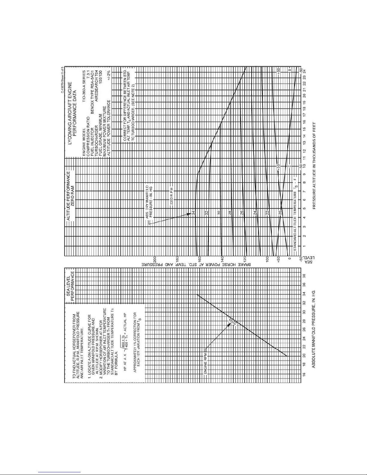
LYCOMING OPERATOR’S MANUAL SECTION 3
O-360 AND ASSOCIATED MODELS OPERATING INSTRUCTIONS
Figure 3-35. Sea Level and Altitude Performance
TIO-360-A Series (Sheet 5 of 5)
3-49
Page 87

SECTION 3 LYCOMING OPERATOR’S MANUAL
OPERATING INSTRUCTIONS O-360 AND ASSOCIATED MODELS
Figure 3-36. Fuel Flow vs Percent Rated Power
HIO-360-E, -F Series
3-50
Page 88
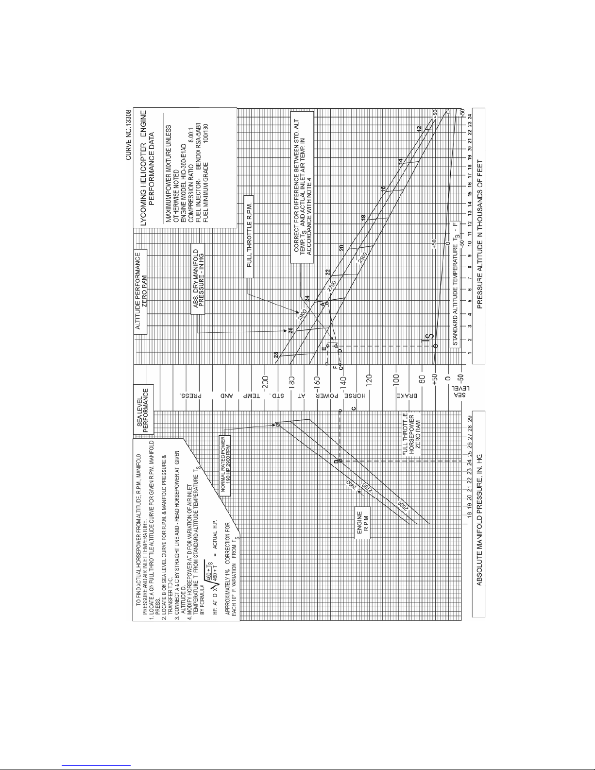
LYCOMING OPERATOR’S MANUAL SECTION 3
O-360 AND ASSOCIATED MODELS OPERATING INSTRUCTIONS
Figure 3-37. Sea Level and Altitude Performance
HIO-360-E Series
3-51
Page 89
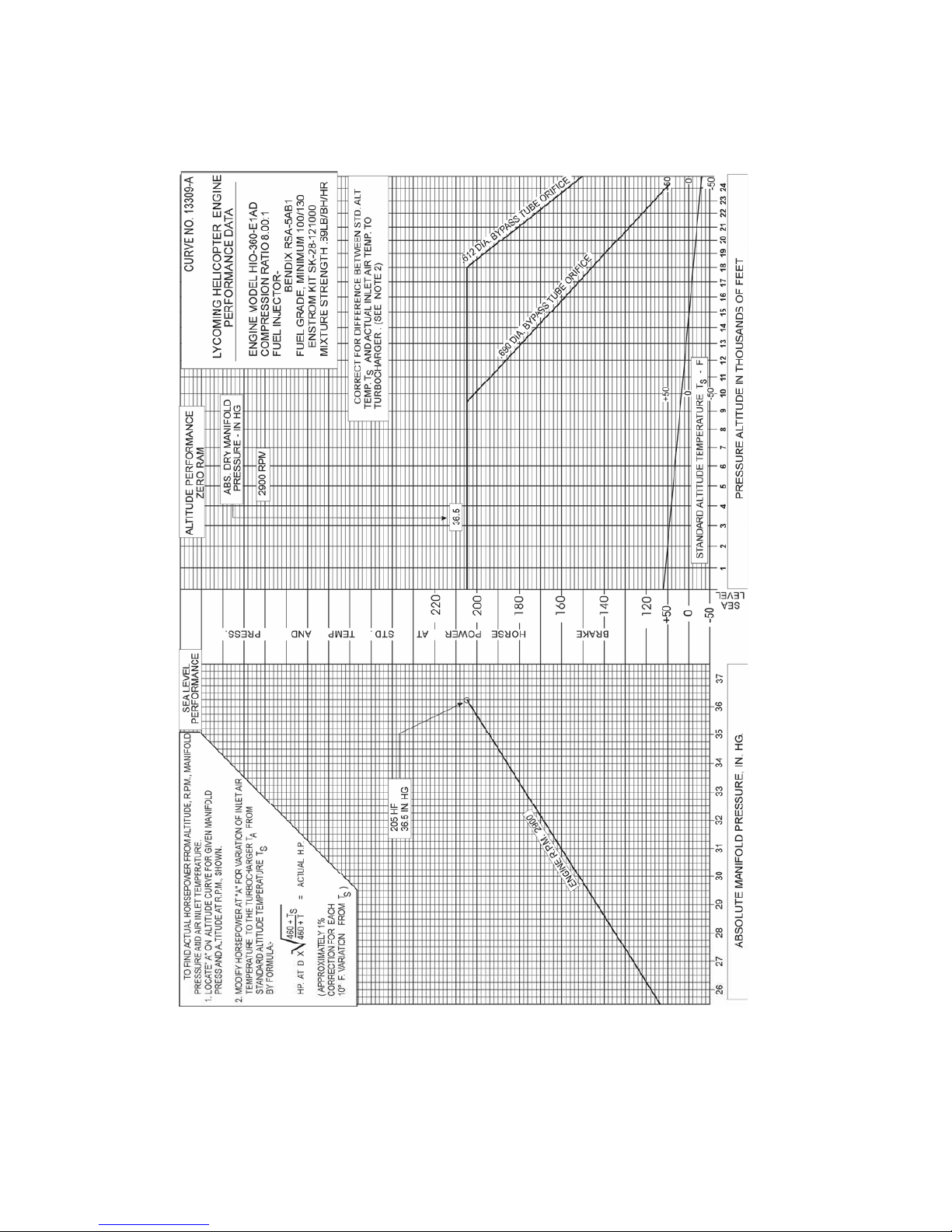
SECTION 3 LYCOMING OPERATOR’S MANUAL
OPERATING INSTRUCTIONS O-360 AND ASSOCIATED MODELS
Figure 3-38. Sea Level and Altitude Performance with Turbocharger Kit SK-28-12100
HIO-360-E Series
3-52
Page 90

LYCOMING OPERATOR’S MANUAL SECTION 3
O-360 AND ASSOCIATED MODELS OPERATING INSTRUCTIONS
Figure 3-39. Fuel Flow vs Percent Rated Power
O-360-A, -C, -F, -G Series; HO-360-C1A
3-53
Page 91

SECTION 3 LYCOMING OPERATOR’S MANUAL
OPERATING INSTRUCTIONS O-360 AND ASSOCIATED MODELS
Figure 3-40. Fuel Flow vs Percent Rated Power
O-360-J2A
3-54
Page 92
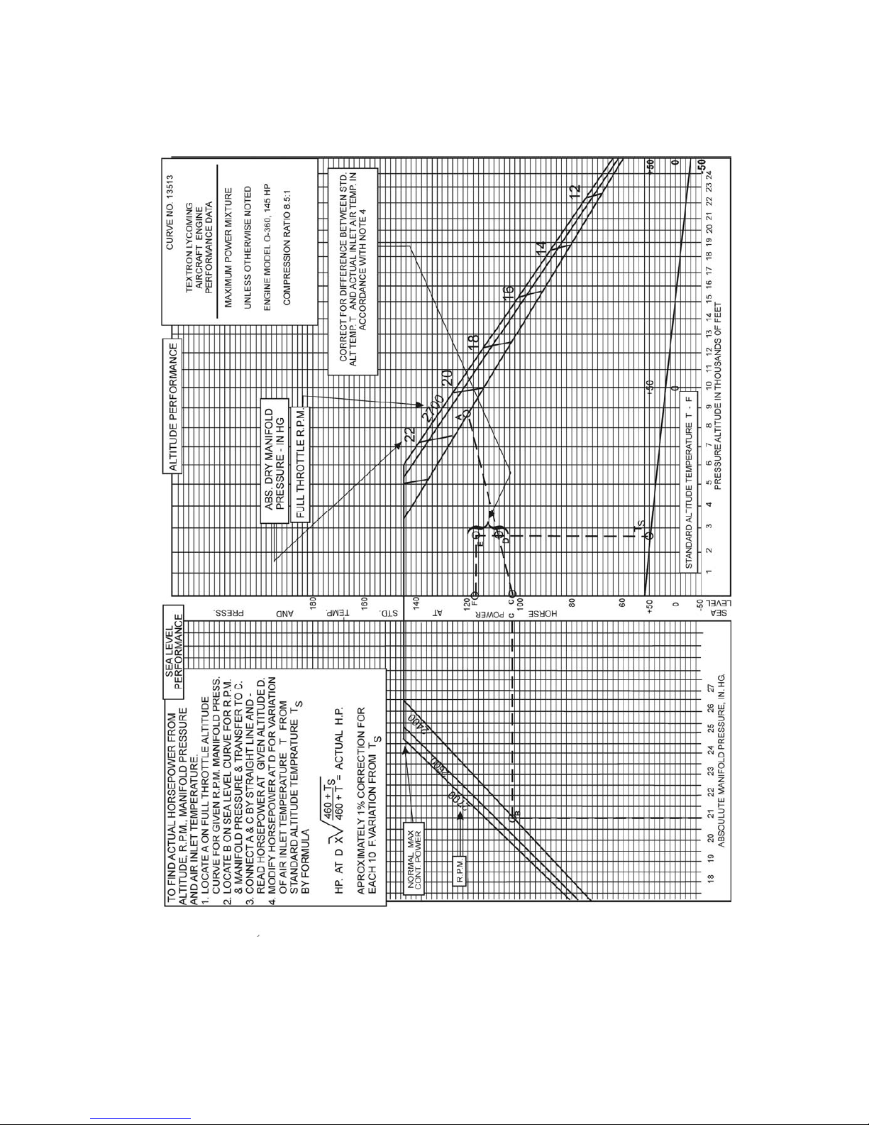
LYCOMING OPERATOR’S MANUAL SECTION 3
O-360 AND ASSOCIATED MODELS OPERATING INSTRUCTIONS
Figure 3-41. Sea Level and Altitude Performance
O-360-J2A
3-55
Page 93
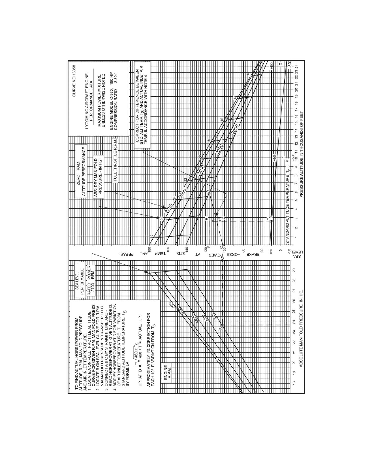
SECTION 3 LYCOMING OPERATOR’S MANUAL
OPERATING INSTRUCTIONS O-360 AND ASSOCIATED MODELS
Figure 3-42. Sea Level and Altitude Performance
O-360-A1A, -A1D, -A1P, -A2A, -A2D, -A2F, -A3A, -A4A, -A4D, -A4M,
-A4N, -A4P, -A1F6, -A1H6, -C1F, -C1G, -C4F, -C4P, -F1A6; HO-360-C1A
3-56
Page 94
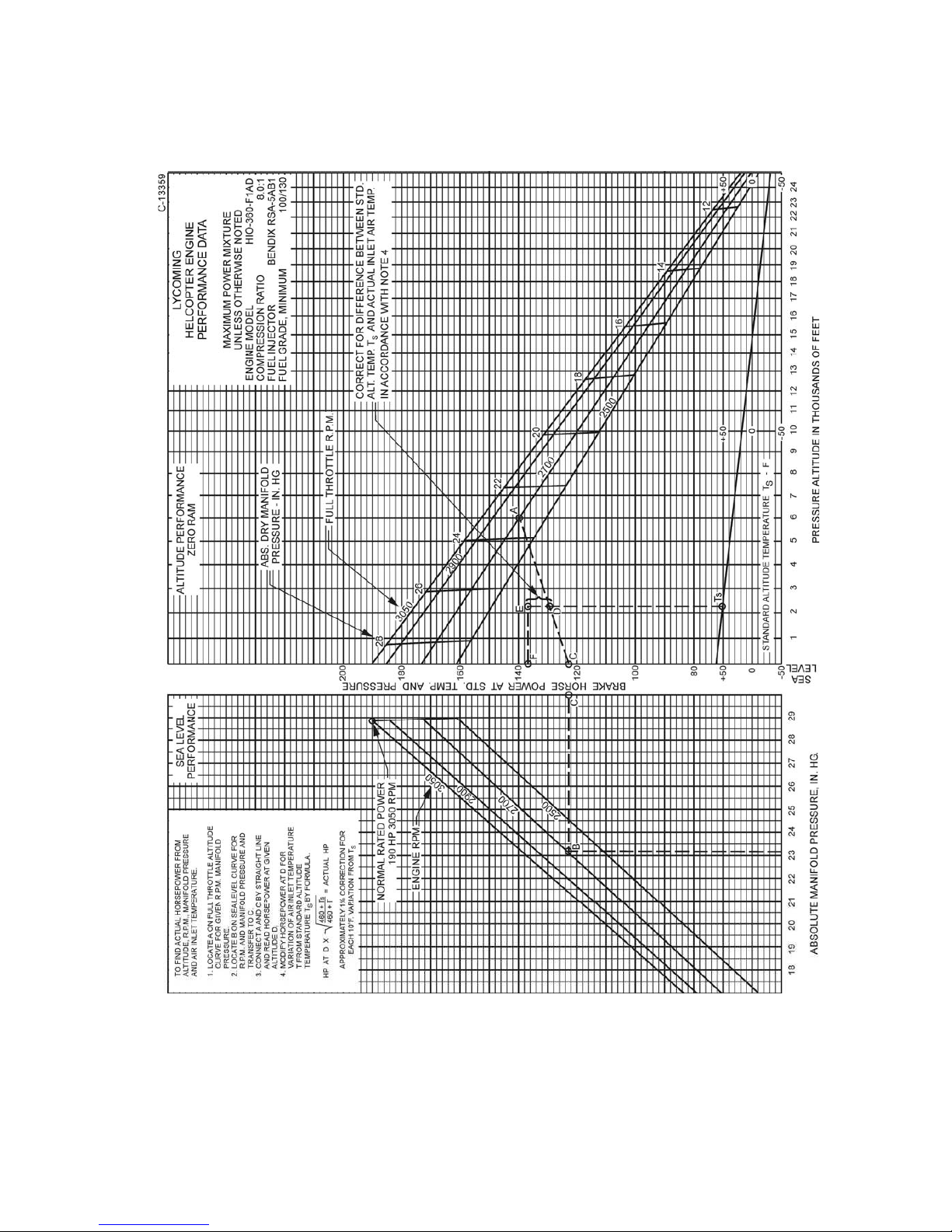
LYCOMING OPERATOR’S MANUAL SECTION 3
O-360 AND ASSOCIATED MODELS OPERATING INSTRUCTIONS
Figure 3-43. Sea Level and Altitude Performance
HIO-360-F Series
3-57
Page 95
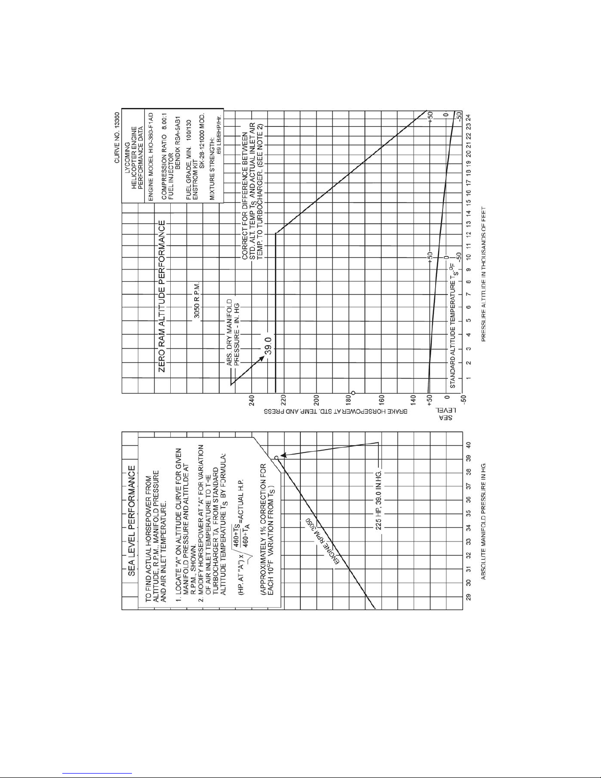
SECTION 3 LYCOMING OPERATOR’S MANUAL
OPERATING INSTRUCTIONS O-360 AND ASSOCIATED MODELS
Figure 3-44. Sea Level and Altitude Performance with Turbocharger Kit SK-28-121000
HIO-360-F Series
3-58
Page 96

LYCOMING OPERATOR’S MANUAL SECTION 3
O-360 AND ASSOCIATED MODELS OPERATING INSTRUCTIONS
Figure 3-45. Fuel Flow vs Brake Horsepower
TIO-360-C1A6D
3-59
Page 97
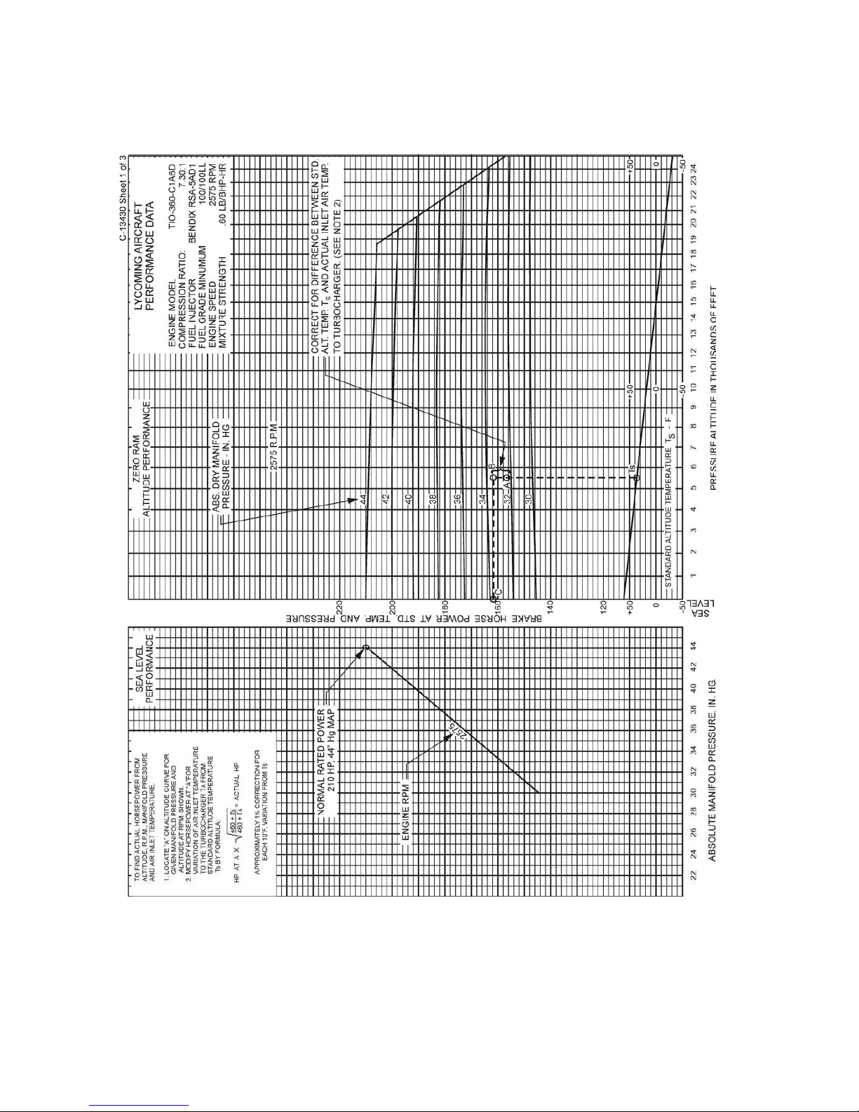
SECTION 3 LYCOMING OPERATOR’S MANUAL
OPERATING INSTRUCTIONS O-360 AND ASSOCIATED MODELS
Figure 3-46. Sea Level and Altitude Performance
TIO-360-C1A6D (Sheet 1 of 3)
3-60
Page 98
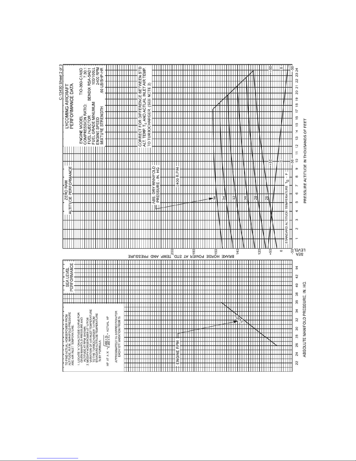
LYCOMING OPERATOR’S MANUAL SECTION 3
O-360 AND ASSOCIATED MODELS OPERATING INSTRUCTIONS
Figure 3-47. Sea Level and Altitude Performance
TIO-360-C1A6D (Sheet 2 of 3)
3-61
Page 99
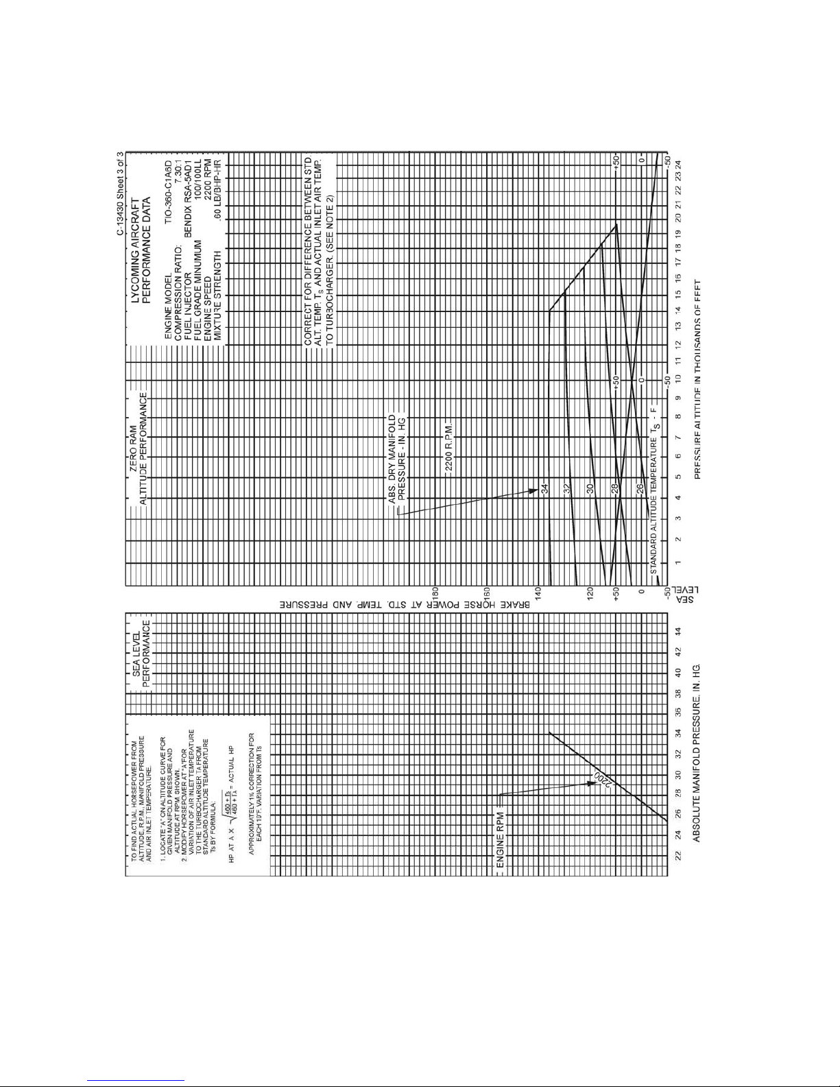
SECTION 3 LYCOMING OPERATOR’S MANUAL
OPERATING INSTRUCTIONS O-360 AND ASSOCIATED MODELS
Figure 3-48. Sea Level and Altitude Performance
TIO-360-C1A6D (Sheet 3 of 3)
3-62
Page 100

LYCOMING OPERATOR’S MANUAL SECTION 4
O-360 AND ASSOCIATED MODELS PERIODIC INSPECTIONS
SECTION 4
PERIODIC INSPECTIONS
NOTE
Perhaps no other factor is quite so important to safety and durability of the aircraft and its
components are faithful and diligent attention to regular checks for minor troubles and
prompt repair when they are found.
The operator should bear in mind that the items listed in the following pages do not constitute a complete
aircraft inspection, but are meant for the engine only. Consult the airframe manufacturers handbook for
additional instructions.
Pre-Starting Items of Maintenance – The daily pre-flight inspection is a checkof the aircraft prior to the
first flight of the day. The inspection is to determine the general condition of the aircraft and engine.
The importance of proper pre-flight inspection cannot be over emphasized. Statistics prove several
hundred accidents occur yearly directly responsible to poor pre-flight.
Among the major causes of poor pre-flight inspection are lack of concentration, reluctance to
acknowledge the need for a checklist, carelessness bred by familiarity and haste.
4-1
 Loading...