

Page 1
DIGITAL CONFERENCE SYSTEM
6600 SERIES
Page 2
INSTRUCTION MANUAL
With the multiple-conference is more and more popularization, the requesting of the
meeting equipments are higher for the multi-functional meeting room, it need the function of
video camera auto-track, voting, electing and interpretation in lots of the discussion meeting
situation. Our company developed the multi-functional meeting control system on the base
of summarizing the experience of multiple-conference and speaking system for many years.
This system designed by the latest digital technology in accordance with IEC914 and ISO
standards. It’s a high effective Multi-functional meeting system for a meeting or conference,
and it’s easy to setting-up, debugging and using without training.
Part A. System Configuration
Conference system main unit, extension power supply, chairman unit, delegate unit,
interconnection cable.
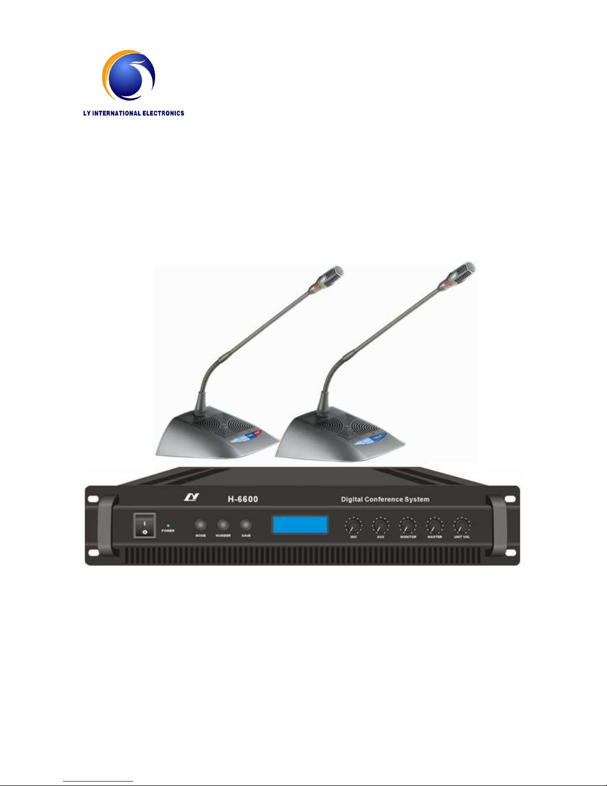
★★★★ Main unit H-6600
1. Power consumption of main unit 400W, each unit can support 64 units delegate and
chairman microphone, it could be extended to support 256 units microphone by
adding more Extension power supply unit.
2. System can support following discuss work mode: Free mode, FIFO mode (1-9
microphone unit), Limit mode (1-9 microphone unit), the working mode will display
one the LCD after setting.
3. With the port for Telephone interface input, telephone meeting is available with
telephone coincidence.
4. Power supply: AC220V/110V 50/60Hz
5. Installation: 19-inch frame
6. Connection:
a. 1 pcs 13m main cable with 8PIN plugs; b. 8 PIN socket for system connection.
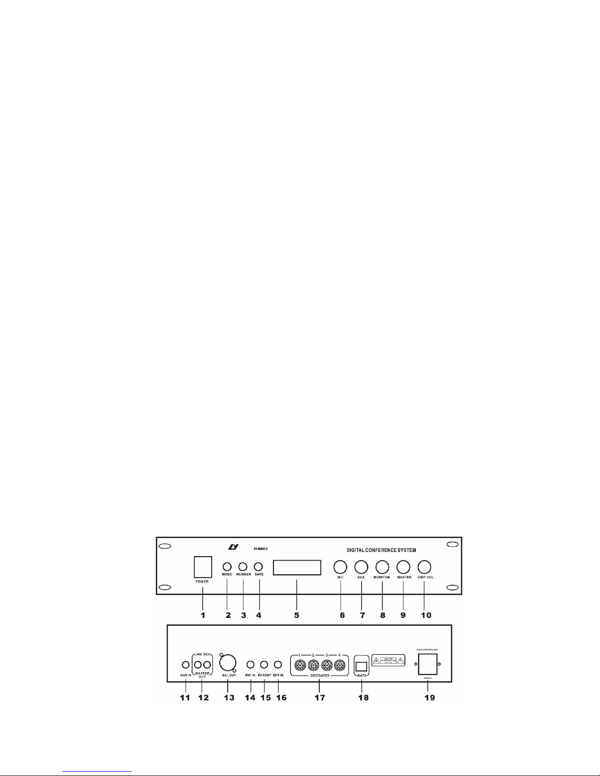
Schematic diagram of main unit
Page 3
1. Power switch
2. Mode: Free mode, FIFO mode (1-9), Limit mode (1-9), C. only mode, music mode.
3. Speaking number key (NUMBER), 1-9
4. SAVE
5. LCD display
6. Volume control of wire microphone
7. AUX volume
8. Monitor volume
9. System volume (MASTER)
10. Unit Volume
11. AUX IN for connect Tel coincidence, DVD, etc.
12. System line out and REC out
13. Balance out
14. Wire microphone port
15. EFX OUT
16. EFX IN
17. System Line Ⅰ, Ⅱ, Ⅲ, EXT
18. Data port for connection video processor
19. Power AC 220V/50Hz
★ Extension power supply unit H-6600E
If the microphone quantity more than 64pcs in one system, then the system need
extension power supply unit to support the conference main unit supply the power to
microphone unit. Each extension power supply unit can support 64 units microphone. And
one system can support up to 254 unit microphone with the extension power unit.
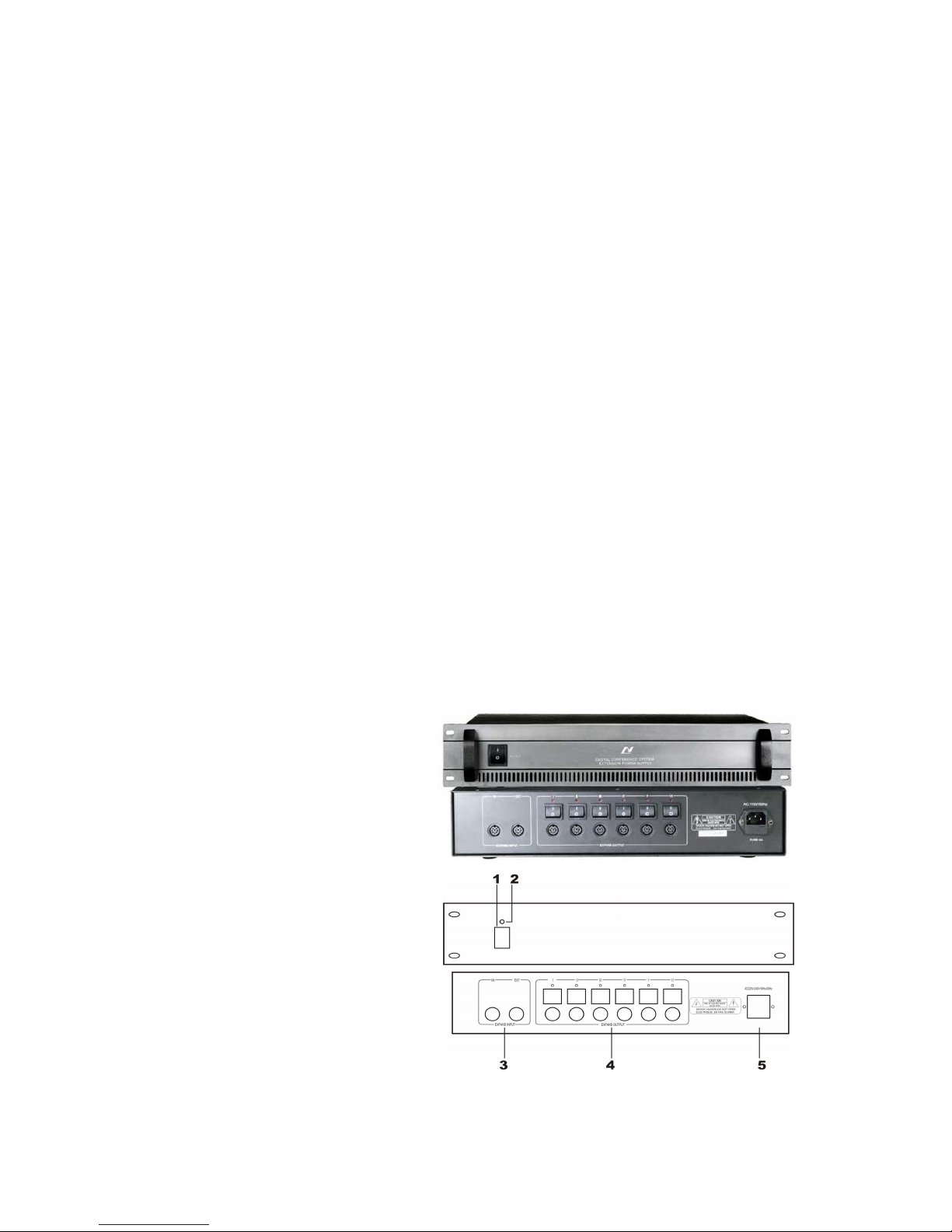
Schematic diagram of main unit
1. Power on/off
2. Power indicator
3. EXPAND INPUT (IN: to the previous
main unit or extension power supply,
EXT: to the next extension power
unit)
4. EXPAND OUTPUT: Six output line for
connect microphone, and each line
with power control.
5. Power AC 220V/50Hz
Page 4
★ Microphone unit H-8200c/d
1) Frequency response: 20Hz-19KHz
2) Sensitivity: -44 dB±2dB
3) Reference sound receiving distance: 20~120cm
4) Portable installation and microphone pipe can be pull out
5) Newly digital design
6) Listening and speaking
7) The system power supply for all the delegate units is provided by the main unit at 24 safe
voltages.
8) With 8-PIN T-type hand-in-hand interconnection cable
9) Built-in high fidelity speaker and earphone jack.
10) Electric capacity type microphone.
11) Extended pipe optional.
12) Volume control of each microphone independently.
13) The annular red indicator lamp could show the state of the microphone.
14) The chairman unit number in the system is unrestricted, can join in any position of the
system.
15) Chairman can turn down delegate MIC by priority button,
16) Indicative sound for chairman unit (optional)
17) C. only mode: only chairman microphone can be turn on.
18) Earphone output jack and wireless microphone input jack for chairman unit (optional)
19) Each microphone equipped with one pcs 2+1.5m branch cable for system connection.
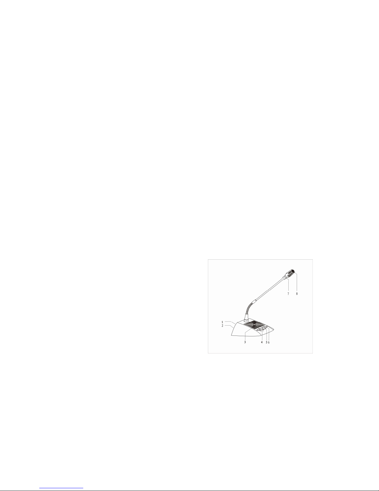
Schematic diagram of microphone unit
(1) 8P connection port
(2) Earphone jack. 3.5mm jack
(3) Build-in loudspeaker
(4) Volume Control
(5) (TALK) ON/OFF button
(6) Priority button. Chairman unit can turn
down delegate MIC by press the priority
button
(7) Annular red indicator lamp
(8) Unidirectional electret MIC
Part B. System connection and debug
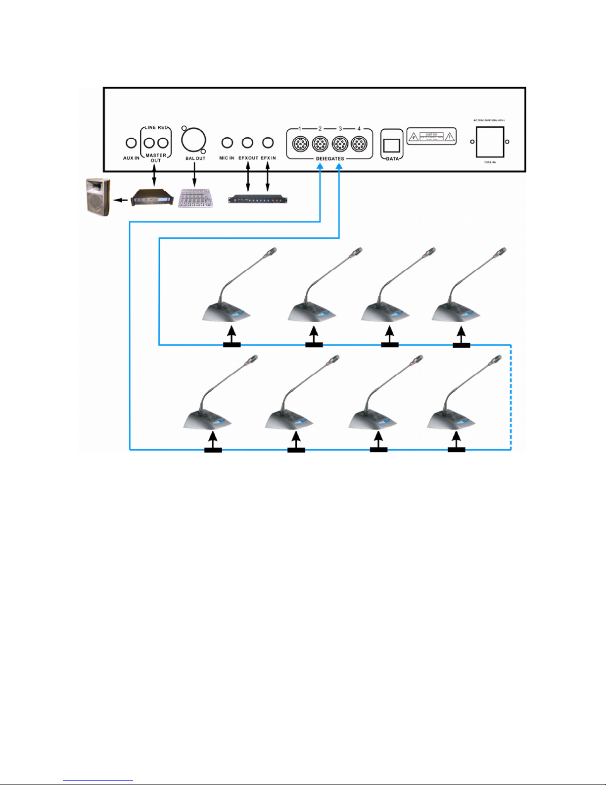
1. Put conference main unit and microphone to the council board.
2. Please connect the male plug of extension cable (13M) to 8PIN port (marked
DELEGATES) of the main unit.
3. Please connect male plug of T-type cable to the female plug of extension cable,
branch cable connect to the 8PIN port of the microphone.
4. Connect the microphone by branch cable one by one in the system.
5. Please embedding the cable in the ground if the cable should not be saw in the
meeting room. (we will make the cable with size of conference projector drawing)
Page 5

6. Please connect the EFX out port to balance input port of frequency shifter by audio
cable, connect the EFX in port to balance output port of frequency shifter by audio
cable.
7. Please connect mixer to output port of main unit if user use mixer.
8. Please connect the amplifier to LINE port of main unit
9. Please connect the speaker to the amplifier.
10. Please connect the recorder to REC port of main unit
11. After connect the system well, turn off the power of the system (the main unit) and
debug the main unit volume (VOL.) to minimum position, other volume control to
middle position.
12. Connect the power cable to the main unit and Power supplier, and then turn on the
main unit to check the power indicator.
13. Turn on one microphone; debug the volume by VOL control in the front panel of main
unit to make sure the system volume is suitable for speaking and listening.
14. Please test the function of main unit one by one first.
15. System working mode setting: Press MODE key of the main unit, the LCD will display
the mode: Free, FIFO, Limit. Please press SAVE key after user select the mode and
microphone number, then the LCD will display the system work mode one the LCD
after save the data.
a. Press MODE key to select “Host mode” on the LCD.
b. Press SAVE key to save the setting
c. Press MODE again to select the working mode: FREE, FIFO, LIMIT mode.
d. Press SAVE key to save the setting, if user select FIFO or LIMIT mode, then
continue to set the number, if select FREE mode, then the setting is finished.
e. Press MODE key to LCD display NUMBER, and press number key to set the number
(1-9).
f. Press SAVE key to save the setting
Part C. System function and operation
★ Microphone unit
a. Delegate unit: Turn on the microphone by press the button (TALK), the red indicator is
on, and then the inner speaker is off delegate can make a speech. Press the button again, the
red indicator is off, delegate can listening other delegate’s speaking.
b. Chairman unit: The chairman unit is the same as the delegate units except an
additional priority button. When this button is put on, the chairman microphone is turn on
while the delegate microphone being turn off until the priority button is released.
c. All microphone units can debug the volume by volume control.
Page 6
★ Technical Data
Model
Data
Main unit
Microphone unit
Voltage AC110~220V/50Hz
DC24V(Supply by 8PIN cable)
Power
consumption
400W 2W
T.H.D.
〈0.05% 〈0.05%
Dimension 482X353X90mm 235X110X54mm / MIC pipe 390mm
S/N
〉75db 〉75db
Sensitivity -56dB Wire microphone
-44dB ±2dB
Frequency
response
20Hz——19KHz 20Hz——19KHz
N.W 11.7Kg 0.9Kg
Color Grey Gray
Installation 19-inch unit Removable
We remain the right to modify any issue without notice in advance
Caution:
Please prevent the equipment dripping by water, do not put the liquid articles such as
vase on the equipment.
The power switch of the equipments is monopole; please pullout the plug if the will not
be used for a long time. The switch has already been turn on when the power indicator lamp
is on, and the switch has already been turn of when the power indicator lamp is off.
This machine has no maintain part, for preventing electric shock from being dangerous,
do not turn on the machine cover without permission. If need to maintain, please contact
sale agent.
The appearance of the products is subject to material object; we remain the right to
modify any issue without notice in advance.
Page 7
★ Schematic diagram
 Loading...