

Page 1

Page 2

LX Zeus v4.0.2
CONTENTS
PART ONE – INTRODUCTION .................................................................................................................... 5
1.1 Preamble.......................................................................................................................................... 5
1.2 Operation ......................................................................................................................................... 6
1.3 Installation procedure (LX Zeus and Eos/Era)............................................................................. 7
Installation of LX Zeus ............................................................................................................................... 7
1.3.1 Installation of LX Eos/Era ............................................................................................................. 7
1.3.2 Screen rotation ............................................................................................................................. 8
1.3.3 Connecting LX Zeus with LX Eos/Era .......................................................................................... 8
1.4 Update procedure ........................................................................................................................... 9
1.5 Technical specifications .............................................................................................................. 10
LX Zeus 2.8 ............................................................................................................................................. 10
LX Zeus 2.8 Retrofit ................................................................................................................................ 10
LX Zeus 4.3 ............................................................................................................................................. 10
LX Zeus 5.5 ............................................................................................................................................. 10
LX Zeus 7.0 ............................................................................................................................................. 10
PART TWO - SOFTWARE .......................................................................................................................... 11
2.1 Display organization and management ...................................................................................... 11
2.1.1 Display organization ................................................................................................................... 11
2.2 Setup .............................................................................................................................................. 14
2.2.1 Setup .......................................................................................................................................... 14
2.2.2 Pilot ............................................................................................................................................ 15
2.2.3 Audio .......................................................................................................................................... 17
2.2.4 LX Eos ........................................................................................................................................ 18
2.2.5 Voice .......................................................................................................................................... 20
2.2.6 Vario-SC ..................................................................................................................................... 21
2.2.7 Indicators .................................................................................................................................... 23
2.2.8 Flarm ......................................................................................................................................... 25
2.2.9 Logger ....................................................................................................................................... 26
2.2.10 Airspace ................................................................................................................................. 27
2.2.11 Wind ....................................................................................................................................... 28
2.2.12 Task ....................................................................................................................................... 29
2.2.13 User interface ......................................................................................................................... 30
2.3 System Setup ................................................................................................................................ 41
2.3.1 Units ........................................................................................................................................... 41
2.3.2 Glider .......................................................................................................................................... 41
2.3.3 Checklist ..................................................................................................................................... 46
2.3.4 Notepad ...................................................................................................................................... 47
2.3.5 Transfer ..................................................................................................................................... 47
2.3.6 Service ....................................................................................................................................... 51
2.3.7 Localisation Settings .................................................................................................................. 54
2.3.8 Brightness .................................................................................................................................. 55
1 | P a g e
Page 3

LX Zeus v4.0.2
3 NAVIGATION MODES ....................................................................................................................... 56
3.1 Navigation in APT / TP or TSK mode .......................................................................................... 56
3.1.1 Sort by filter ................................................................................................................................ 56
3.1.2 Main graphic navigation page .................................................................................................... 56
3.1.3 Second navigation page (1st subpage) ...................................................................................... 57
3.1.4 Third navigation page (2nd subpage) .......................................................................................... 58
3.2 APT mode (navigation to airports) ............................................................................................. 58
3.3 How to select an airport?............................................................................................................. 59
3.3.1 APT selection from NEAR function ............................................................................................ 60
3.4 TP mode (navigation to turnpoints) ............................................................................................ 60
3.4.2 Selecting Turn-points ................................................................................................................. 63
3.4.3 Uploading TP photo ................................................................................................................... 64
3.5 TSK mode (navigation on task) ................................................................................................... 65
3.5.1 Task organization ....................................................................................................................... 65
3.5.2 Task selection ............................................................................................................................ 65
3.5.3 Task creation by hand ................................................................................................................ 66
3.5.4 Task Functions ........................................................................................................................... 69
3.5.5 MOVE Function (during flight) .................................................................................................... 71
3.5.6 Task Zoom ................................................................................................................................. 72
4 AIRSPACE MANAGEMENT .............................................................................................................. 73
1.1 Basic airspace settings ................................................................................................................ 73
4.1.1 Hide airspace above .................................................................................................................. 73
4.1.2 Other settings ............................................................................................................................. 73
4.1.3 Define appearance of airspace related to zoom level ............................................................... 73
4.1.4 Disabling airspace sections ........................................................................................................ 75
5 GPS SIGNAL MANAGEMENT .......................................................................................................... 76
5.1 Colibri II socket ............................................................................................................................. 76
5.2 Flarm plug ..................................................................................................................................... 76
5.3 LX Eos – CAN plug ....................................................................................................................... 76
5.4 GPS signal for navigation ............................................................................................................ 76
6 LX ZEUS AND LX EOS/ERA ............................................................................................................. 77
6.1 LX Eos/Era power management .................................................................................................. 77
6.2 LX Eos/Era – Zeus interaction ..................................................................................................... 78
6.2.1 Commands and declaration transfer to LX Eos/Era................................................................... 78
7 LX ZEUS AND COLIBRI II ................................................................................................................. 79
7.1 Colibri II power management ...................................................................................................... 79
2 | P a g e
Page 4

LX Zeus v4.0.2
7.2 Colibri II – LX Zeus interaction .................................................................................................... 79
7.2.1 Commands and declaration transfer to Colibri II/Eos/Era .......................................................... 79
8 LX ZEUS AND FLARM ...................................................................................................................... 80
8.1 Flarm external displays ................................................................................................................ 81
8.2 Task declaration into Flarm ......................................................................................................... 81
8.3 Transferring files from Flarm ...................................................................................................... 81
8.4 LX Flarm RedBox / LX Flarm MiniBox update ........................................................................... 82
8.5 Flarm PINOUT ............................................................................................................................... 82
9 LX ZEUS AND GARRECHT .............................................................................................................. 82
9.1 LX Zeus and Garrecht TRX-1090 ADSB / TRX-2000 .................................................................. 82
9.2 LX ZEUS and Garrecht TRX-1500 ............................................................................................... 82
10 LX REMOTE STICK ........................................................................................................................... 83
10.1 Use of LX Remote Stick ............................................................................................................... 83
10.2 LX Remote Stick on second seat ................................................................................................ 83
11 LX JOY ............................................................................................................................................... 84
11.1 General .......................................................................................................................................... 84
11.2 Button description ........................................................................................................................ 84
11 SECOND SEAT UNIT......................................................................................................................... 88
1.1 Connecting Vario Indicator and LX Remote Stick ................................................................... 88
11.2.1 Secondary Vario Indicator setup ............................................................................................ 88
11.3 Connecting LX Eos repeater to LX Zeus on second seat ........................................................ 89
11.4 Interaction LX Zeus – LX Zeus Second seat .............................................................................. 89
11.4.1 TSK / TP / APT exchange ...................................................................................................... 89
11.4.2 Downloading flights from Second seat .................................................................................. 89
PART THREE – FLYING ............................................................................................................................ 90
12 FLYING WITH LX ZEUS .................................................................................................................... 90
12.1 Flight preparation on the ground ................................................................................................ 90
12.1.1 Before take off ........................................................................................................................ 90
3 | P a g e
Page 5

LX Zeus v4.0.2
12.2 During flight .................................................................................................................................. 92
12.2.1 Set MacCready (MC), Ballast, Bugs and QNH ...................................................................... 93
12.2.2 Statistics ................................................................................................................................. 93
12.2.3 Follow me ............................................................................................................................... 96
12.2.4 Special functions .................................................................................................................... 96
12.2.5 Task Start ............................................................................................................................... 98
12.2.6 Task Finish ........................................................................................................................... 100
12.2.7 Flying Assigned Area Task (AAT) ........................................................................................ 100
12.2.8 Final glide (FG) calculation .................................................................................................. 101
12.2.9 Finish line crossing .............................................................................................................. 101
12.2.10 Thermal assistant................................................................................................................. 101
12.2.11 Flarm management .............................................................................................................. 102
12.2.12 Attitude and heading reference system (AHRS) .................................................................. 103
12.3 After landing ............................................................................................................................... 104
12.3.1 Downloading flights .............................................................................................................. 104
12.4 ICAO charts ................................................................................................................................. 106
PART FOUR - MISCELLANEOUS ........................................................................................................... 107
13 INSTALLATION (OTHER COMPONENTS)..................................................................................... 107
13.1 Installation of LX Flaps sensor ................................................................................................. 107
13.2 Electrical installation .................................................................................................................. 107
13.2.1 LX Zeus with Vario (USB-D 60) ........................................................................................... 107
13.3 Installation of second seat units ............................................................................................... 110
13.3.1 Electrical installation ............................................................................................................ 110
14 EXPLANATION OF NAVBOX TERMS ............................................................................................ 111
15 FAQ (FREQUENTLY ASKED QUESTIONS) .................................................................................. 114
4 | P a g e
Page 6

LX Zeus v4.0.2
PART ONE – Introduction
1.1 Preamble
Why LX Navigation?
LX Navigation is one of the oldest glider navigation brands. Its founders started experimenting with glider
computers way back in the '70-ies and the Company has been working on improving your flight
performance ever since.
Throughout the last 40 years or so it has been working on instruments that most pilots will have used at
some time. In fact our equipment can be found in almost any gliding club !
Our equipment has always been ground-breaking.
Our motto?
Be the first. Be the best. Be different.
Why Zeus?
Because Zeus is a top of the line product. Crème de la crème.
Used by pilots from all over the world, our instruments offer the best for both cross country soaring and
competitions. The LX Zeus is the latest in this tradition.
Devices
We offer a wide range of instruments suitable for both club and competition soaring.
Our systems combine two components:
First, a glider computer (LX Zeus) which is used for calculating and displaying all of the key information
used by pilots. This glider computer is the brain of the operation.
The second part of the system is a variometer (Eos, Helios, and Era). Its job is to gather the information
which the Zeus uses. The vario has pressure connections as well as the GPS antenna connection which is
required for IGC logs.
There is a wide variety of choice for varios and for LX Zeus display sizes.
All our varios are standalone devices which can be used without a glider computer for displaying basic
flight parameters such as final glide information, Speed Command (SC) as well as simple navigation. Our
varios also have an internal battery which means that your IGC logs do not depend on your glider`s
batteries.
5 | P a g e
Page 7

LX Zeus v4.0.2
System extensions (second seat unit, remote control (LX Joy), compass, NavBox, MOP, Flap sensor, AHRS
...) are also possible. Everything is connected using a CAN bus (single cable for power and data). All
connections are plug and play, which means no specialist is required to install the system.
1.2 Operation
Front panel interface
Communications between the pilot and the instrument is done via two rotary knobs and 8 push buttons.
All buttons and rotary switches have a double push function (short and long press). All buttons are
labelled which makes unit manipulation very easy. The top labels are selected with a short press.
Bottom labels are selected with a long press. On Zeus 2.8” and Zeus 4.3” there is a 4-4 button
arrangement. On other screen sizes the button arrangement is 5-3.
Both rotary knobs are multifunctional as follows:
Default functions:
Volume rotary knob
o Volume adjustment function - scroll
o Select (TP, APT, TSK) - short press
o Shortcuts - long press
Zoom rotary knob
o Zoom adjustment function – scroll
o Open more options (TP, APT, TSK) - short press
o Edit NavBoxes – long press
In edit:
Volume rotary knob: bigger steps when selecting values and escape/cancel by pressing it
Zoom rotary knob: scrolling and press confirmation
USB/SD
There are two ways of transferring files: either via USB or via SD port. A standard USB-A female port is
available on each device (on Zeus 2.8 slim USB keys should be used). The port is exclusively used for data
transfer and firmware updates. The micro SD port is only used when Flarm is connected (Flarm Red Box,
Swiss Flarm and optionally Flarm Mini Box). The micro SD port is used for direct communication with
Flarm, which means downloading flights stored on Flarm, uploading declaration and Flarm firmware
updates.
Back panel interface
On the back side of the unit there are the following connectors:
2x CAN bus*
2x User ports
Flarm port (12 V power and data) *
Flarm display output
USB – A port
6 | P a g e
Page 8

LX Zeus v4.0.2
Note!
Check labels near pneumatic connections on LX Eos/Era, during pneumatic tube connection
process to ensure correct connection.
* CAN bus connects LX Zeus to:
LX Eos (57/80)
LX Era (57/80)
Second seat unit
LX Joy
LX NavBox
LX Flaps sensor
LX MOP
LX AHRS
1.3 Installation procedure (LX Zeus and Eos/Era)
Installation of LX Zeus
The dimensions of larger units (4.3, 5.5 and 7.0) do not match air norm standards (57 or 80mm). A new
cut out in the panel is necessary. There are two ways to prepare the panel:
The first option is to buy a new panel from the glider manufacturer and the second is to upgrade the
existing panel. The user can also do a panel upgrade and, in that case, basic experience in fiberglass
technology will help. (LX Navigation can provide additional instructions on how to rebuild the panel by
yourself – just ask!)
Every unit (except the 2.8 inch, which fits an 80mm instrument hole) is supplied with a carbon which makes
it possible to make the LX Zeus cut out by hand. If a CNC solution is planned, then please ask for .dwg file.
1.3.1 Installation of LX Eos/Era
The unit occupies one 57 mm or 80 mm standard cut-out. The maximum dimensions of LX Eos/Era 57 are
60x60 mm max and they do not exceed the dimensions of classic pneumatic instruments. LX Eos/Era 80
mm are 82x82 mm max. LX Eos/Era is shallow, which means that there shouldn’t be any problems
installing it as regards space behind the panel.
7 | P a g e
Page 9
LX Zeus v4.0.2
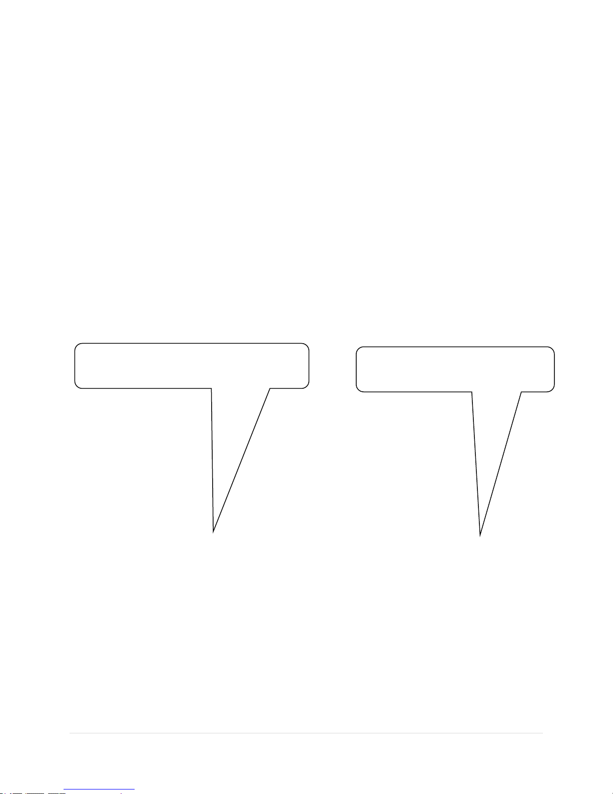
At this side the rounded rubber is touching the
back plate of display, do not push it too tight
At this side the rounded rubber is
pressed fully to the plate.
1.3.2 Screen rotation
The screen can be rotated by using password 9109 under Setup > Service > Admin password. The buttons
must be rotated by hand. Follow the procedure below:
1. Open the unit (remove all screws and cover)
2. Move rounded rubber to the middle
3. Take out the button and rotate it to the proper position
4. Put button back on blue button (be careful that blue button is inside the black hose)
5. Put rounded rubber back to the first position (be careful with the Rotary knobs as the rubber
must not be pushed all the way in)
1.3.3 Connecting LX Zeus with LX Eos/Era
This part of the installation is easy and doesn’t require any specialists. LX Zeus and LX Eos are connected
via a CAN bus cable. Connect one end of the cable into Eos CAN bus port and the other into any of the CAN
bus ports on the LX Zeus. LX Zeus receives power from LX Eos/Era. All data from and to LX Zeus and LX
Eos/Era goes via a single CAN cable.
LX Eos receives power via two power lines, which should be connected to 12V glider power source and
ground. The red wire is +12V and blue wire is Ground.
8 | P a g e
Page 10
LX Zeus v4.0.2
Important!
When LX Eos/Era is connected, the terminator must not be connected to the system, because there
is a terminator integrated in LX Eos. Only one terminator should be used at once.
12 V
Connect supplied power cable with switch to 2-pole connector on LX Eos/Era.
LX Eos/Era and LX Zeus turn ON when the user switches the power ON. This is not the case if LX Eos/Era is
a standalone version, which has different hardware and requires a push on the knob to turn ON.
For more information about LX Eos/Era refer to LX Eos/Era manual!
1.4 Update procedure
LX Zeus software is constantly being upgraded. Please contact your local dealer for the latest upgrade.
The latest version, together with a change log, is always available on our website (www.lxnavigation.com).
The upgrade procedure is very simple, just follow these steps:
Put the upgrade file (Zeus-x.y.z.kus) onto a USB stick
Insert USB stick into LX Zeus
Turn on LX Zeus (If it is already powered on it should be restarted)
Hold VARIO/FLARM button until the blue window opens
Select upgrade with a push on the Zoom rotary knob
Find the update on the USB stick
Select the file with a push on the Zoom rotary knob
Wait for installation, when an Initial setup screen shows then the update is finished
All devices connected to CAN bus will be automatically updated
In a Double-seater configuration the system may ask if this is FIRST or SECOND seat (confirm
correct one)
In case of Double-seater configuration repeat the whole procedure on the second seat LX Zeus
9 | P a g e
Page 11

LX Zeus v4.0.2
1.5 Technical specifications
LX Zeus 2.8
This version of Zeus can be installed into any standard 80 mm panel cut out and therefore does not require
an instrument panel upgrade. Display orientation is only landscape.
LX Zeus 2.8 Retrofit
Zeus 2.8 Retrofit is the same display size as Zeus 2.8 but differs in hardware. Vario (USB-D) module is inside
the main unit and only a vario indicator is needed. The back of the instrument is the same as for LX 5000
(2x 15pin connectors). If the LX 5000 had a 25-pin connector, an adapter for 2x15 to 25-pin is needed,
which can be supplied from LX navigation. An old vario indicator can also be used. The attraction of the
Retrofit solution is that all wiring remains as is.
LX Zeus 2.8 Retrofit is not available for purchase anymore so this instruction relates only to those pilots
who have this system already fitted.
LX Zeus 4.3
This version has a 4.3-inch display with 800x480px resolution and has the following outline dimensions:
83x136x52 mm
LX Zeus 5.5
This version has a 5.5-inch display with 640x480px resolution and has the following outline dimensions:
106x146x52 mm
LX Zeus 7.0
This version has a 7.0-inch display with 800x480px resolution and has the following outline dimensions:
110x190x52 mm
10 | P a g e
Page 12

LX Zeus v4.0.2
Speed
Follow me
Final glide
Wind
Header
Digital Speed
Vario
Airspace info
PART TWO - Software
2.1 Display organization and management
The available information can be personalised and adjusted to meet the user`s requirements and is set
out in the following paragraphs.
2.1.1 Display organization
LX Zeus display consists of the following:
Geographic map.
Bottom row (NavBox line).
Header.
Indicators.
2.1.1.1 Indicators
Indicators are elements on the display which can be edited (existence, size, position, transparency). See
Setup/Layout for details.
Here is a list of available indicators:
Header
Speed indicator
Sliding speed indicator
Speed indicator classic (circular)
Digital speed indicator
Variometer (bar)
Variometer classic (needle)
Wind indicator
Final glide indicator (selected MC)
Final glide (sel. MC, terrain aware)
Final glide indicator (MC 0.0)
Thermal assistant (available when
you are circling)
Compass
Compass needle
11 | P a g e
Page 13

LX Zeus v4.0.2
Compass assistant (assists the pilot when flying with a compass module)
Airspace info (information about closest airspace. If no airspace is within selectable limits this
indicator is transparent.)
Limitations (Start conditions)
Map scale
AHRS
Flaps position
Follow indicator (shows position of a Flarm object being followed)
Flarm indicator (used to show Flarm collision warnings. If no warning is available this indicator is
transparent).
Best alternate APT info (shows the pilot the best alternate airfield nearby (APT database) besides
the one being navigated to). If no APT is available this indicator is transparent.
2.1.1.2 NavBox line customization
The bottom row consists of customisable NavBoxes. This
means that the pilot is able to create his own configuration.
This simple procedure is also available during flight. The
user can set different configurations for TP, APT and TSK
navigation. It is possible to copy configurations from one
page to another. (Done under Setup>Layout). The
procedure starts with a long press on the Zoom rotary
knob. After the long press a frame appears around the first
NavBox. Rotating the Zoom rotary knob positions the
frame. When the desired frame position is reached, a short
press of the Zoom rotary knob again will open a list of
available NavBoxes.
12 | P a g e
Page 14

GENERAL
G-force
Circling radius
Last full turn time
Recommended flaps position
Current flaps position
Wind speed
Wind direction
Air temperature
Distance in NM to selected TP/APT
Distance to selected TP/APT
Off course distance
OLC distance
OLC home distance
OLC speed
OLC speed in last hour
OLC score
Horizontal distance from airspace
Vertical distance from airspace
Arrival QFE (no reserve)
ETE - Estimated time en-route
Current efficiency
Average efficiency
Required efficiency
Track
Bearing
Radial TP/APT
Compass heading
Digital clock
Analog clock
Flying time
ETA (current speed)
ETA (average speed)
ETA (McCready speed)
2.1.1.3 List of available NavBoxes
SPEED
Indicated air speed
True air speed
Ground speed
Vario
Average vario
Netto vario
Average netto vario
Relative vario
Optimum speed to fly
ALTITUDE
Altitude QFE
Altitude QNH
Altitude QNH in ft
Maximum altitude QNH
Altitude IGC
Altitude GPS
Above ground level
Flight level
Thermal gain
Thermal last 30
Thermal average
Thermal all
Set MacCready
Required MacCready
Sink speed
Final glide (selected MC)
Final glide (with terrain)
Final glide (MC 0.0)
TASK
Time on task
Time on leg
Time to go
Required speed
Task speed
Task speed in last hour
Task elapsed distance
Task remaining distance
Task delta time
Team code
Team bearing
Team distance
Leg speed
Task distance
LX Zeus v4.0.2
13 | P a g e
Page 15

LX Zeus v4.0.2
Note!
All settings active at the moment of
new pilot creation under “Pilot” will
be adopted.
To terminate the process, press the Volume rotary knob (“Go back”).
Up to nine bottom rows can be used selectable with 1-4 push buttons. To create a new row simply press 14 and a new row will open. The display configuration may consist of one, two or three NavBox rows. See
Setup/Layout for details.
2.1.1.4 Header
The header cannot be customized. Only the transparency can be set: go to Setup>Layout. From left to right
there is information about:
Current navigation page (TSK, TP or APT)
Current navigation turn-point
Distance and steering information to get to the navigation point
LX Joy status (N = normal, Z = zoom, P = pan)
Battery status
GPS signal status
Current time in selected format (hh:mm:ss)
2.2 Setup
2.2.1 Setup
The setup menu is available after a short press on the
push button labelled SETUP. The menu is divided into two
sections (Pilot and System settings). System settings are
settings that are valid for the whole system and are not
pilot specific settings. Pilot settings may vary from pilot to
pilot according to individual requirements. Icons with text
will help in finding the menu of interest.
Use Zoom rotary knob and rotate it to find the
menu of interest (selected icon is highlighted)
Use push function of Zoom rotary knob to enter
menu
2.2.1.1 Pilot specific settings
The data stored in this part of Setup is pilot specific data.
After pilot selection on initial setup, the data of an
individual pilot becomes active. All settings are saved to
the pilot profile and are active when the pilot is selected
(reserve altitude, logger settings, NavBox container,
layout settings, task colours etc.) It is possible to
export/import user profile settings with a USB stick.
14 | P a g e
Page 16

LX Zeus v4.0.2
2.2.2 Pilot
The Pilots name and certain personal data
can be stored. All stored pilot names will be
offered during initial setup and selecting a
pilot is mandatory. The system offers a
default user profile with the name
DEFAULT which can be used as a default pilot.
Furthermore, plenty of empty positions are offered and
this can be used for another pilot using the instrument.
Some additional parameters can be entered, such as
pilot’s weight, default ballast and reserve altitude – all
settings are used for final glide calculation.
TDT calculation (task delta time)
This information is shown in a NavBox and presented only if the task time has been set. If task time is set
the unit will recognize this task as assigned area task (AAT). The purpose of TDT is to inform the pilot of
early or late arrival to the finish line/cylinder.
For TDT calculation one can choose between 4 different options:
• Average task speed is based on current task speed
• MacCready is based on actual based MC value
• Ground speed is based on average ground speed in last 20 seconds
• Combined (default) is based on multiple parameters including: selected MC, wind
sped/direction, polar, bugs, ballast, reserve altitude. This is the recommended method for
calculation
AAT calculation
To help the pilot optimize distance inside a sector there are equidistant lines displayed. They are shown
inside the active zone. This feature is only available in automatic AAT mode. Flying along these lines will
not increase the distance and may lose time on task. Ideally one should fly perpendicular to the lines.
AAT calculation offers two options:
Automatic (default)
This method doesn’t need any pilot assistant at all and the pilot can turn to next turn point at any time
without using any commands. Zeus will automatically detect the optimum point in every sector on
task. Switching to the next turnpoint is performed by:
o Reaching the line which is crossing the centre of the sector or a moved turnpoint. Reaching
this point will only switch navigation to next turnpoint (for your information). One can still
proceed inside this sector and Zeus will find the optimum position inside the sector to start
the new leg. A new leg in statistics will start automatically when the optimum point is reached.
o Leaving an active sector. When the glider is more than 5km out of the sector it will switch. This
is done only if there was no automatic switch inside the sector (you did not cross the line over
centre of the sector or moved point) or if the next Next TP button was not pressed manually
whilst inside the sector.
o Using Next TP button. This command can be used without influencing statistics. It will only
change navigation data.
15 | P a g e
Page 17

LX Zeus v4.0.2
Manual switching requires specific action in every sector on task. The Next TP button has to be
pressed to switch to next Turnpoint. The position at which Next TP button was pressed is then
used for task statistic calculation. In the case of a wrong decision the pilot should use the leg restart
function and, when he is ready again, he should then press next TP.
Limiting altitude
Limiting altitude means altitude limit set that will turn on the altitude warning alert.
When this is set, the pilot can choose:
Warn before
Warn with audio signal
Show dialog when over limit
User defined warnings
The pilot can make user defined warnings, which will
give and alert when the conditions assigned have
been fulfilled.
To make a user defined warning go to Setup > Pilot
select User defined warnings and select “add new”.
1. Then can be defined:
o Conditions check frequency (How
often Zeus checks if the conditions
are fulfilled).
o Repeat interval (How often should
the warning be repeated).
o Auto close after… (the length of
time the warning should remain
before disappearing).
2. To add the text to appear on the screen
as a warning, select Text, and add the
desired text.
3. The final step is to add conditions (one or
more) which will determine when the
warning appears:
o Choose a parameter (Choose from -
flight time, air temperature, ballast,
air speed, QFE altitude, battery
voltage, distance to destination (to
current TP or APT)
o Operator (Choose relation to the
reference parameter)
o Value (depending on chosen
parameter)
16 | P a g e
Page 18
LX Zeus v4.0.2
o Connect condition with (if there is more than one condition, select what conditions are
to be connected with AND or OR)
o When your condition is complete select “Add cond” (if you want to remove it, select
“Clear cond”).
o When finished select Exit
It is possible to edit all user-defined warnings, and to delete them.
Other useful information
User (pilot) settings can also be saved to the USB stick and importing a user done by pressing the buttons:
Import user (VARIO/FLARM) and Save user (TSK/MOVE). There is also an option to a set password to each
pilot profile to prevent other pilots flying with the same unit and changing the pilot settings (this function
was specially developed for flying in clubs). After a press on clear password the password will be removed.
To delete a user, simply select delete user.
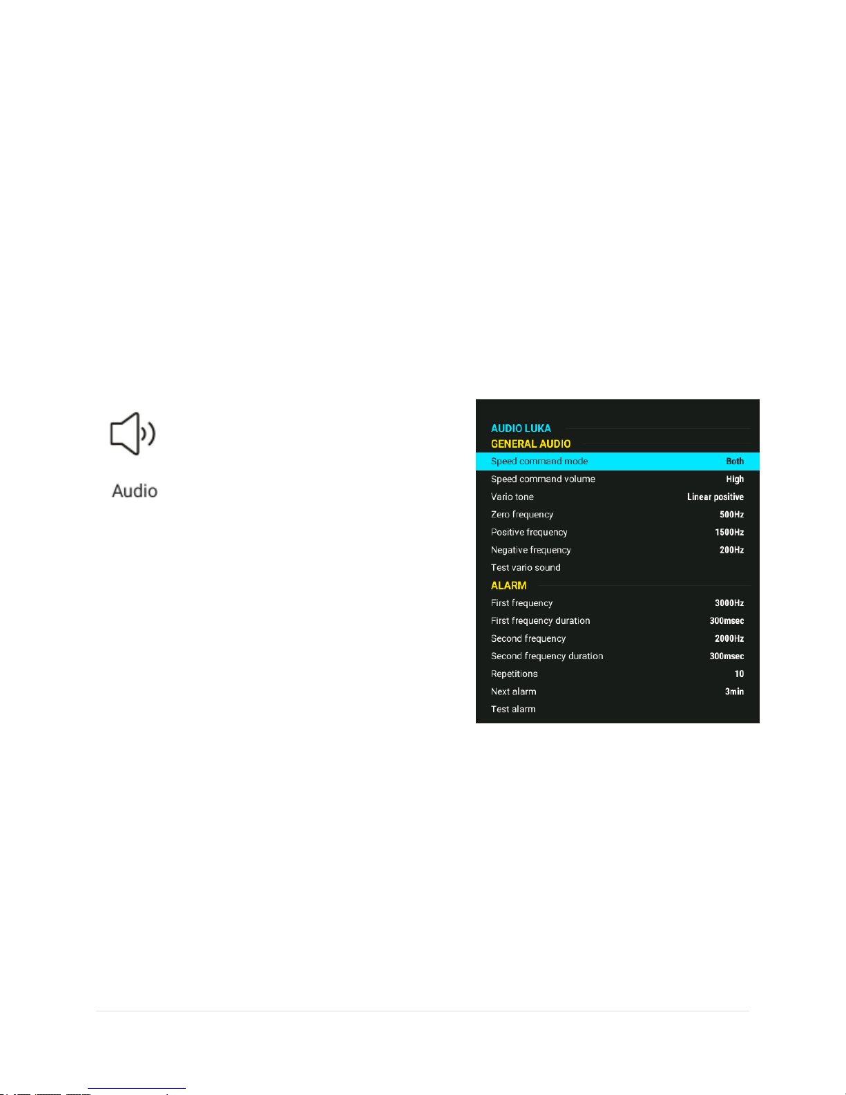
2.2.3 Audio
This menu defines audio configuration. The
audio generator is a part of the vario unit
(USB D 60), but settings are stored in LX
Zeus. Audio settings do not appear if there
is a LX Eos connected to the system.
Instead there is a LX Eos icon where the LX Eos can be set
up. For more information please check the LX Eos chapter.
Speed command mode:
• Defines audio in SC. The most commonly used
setting is both which means SC will beep in both positive
and negative deflections
Speed command volume:
• Defines audio volume in SC; it may be increased or
decreased
Vario tone:
• Defines audio in vario mode; the frequencies can be adjusted and also the types of audio; use
Test vario after adjustment
Alarm: The audio generator is also capable of generating some alarms (warnings) combining two
frequencies. Set frequencies and time intervals and use Test to check.
17 | P a g e
Page 19
LX Zeus v4.0.2
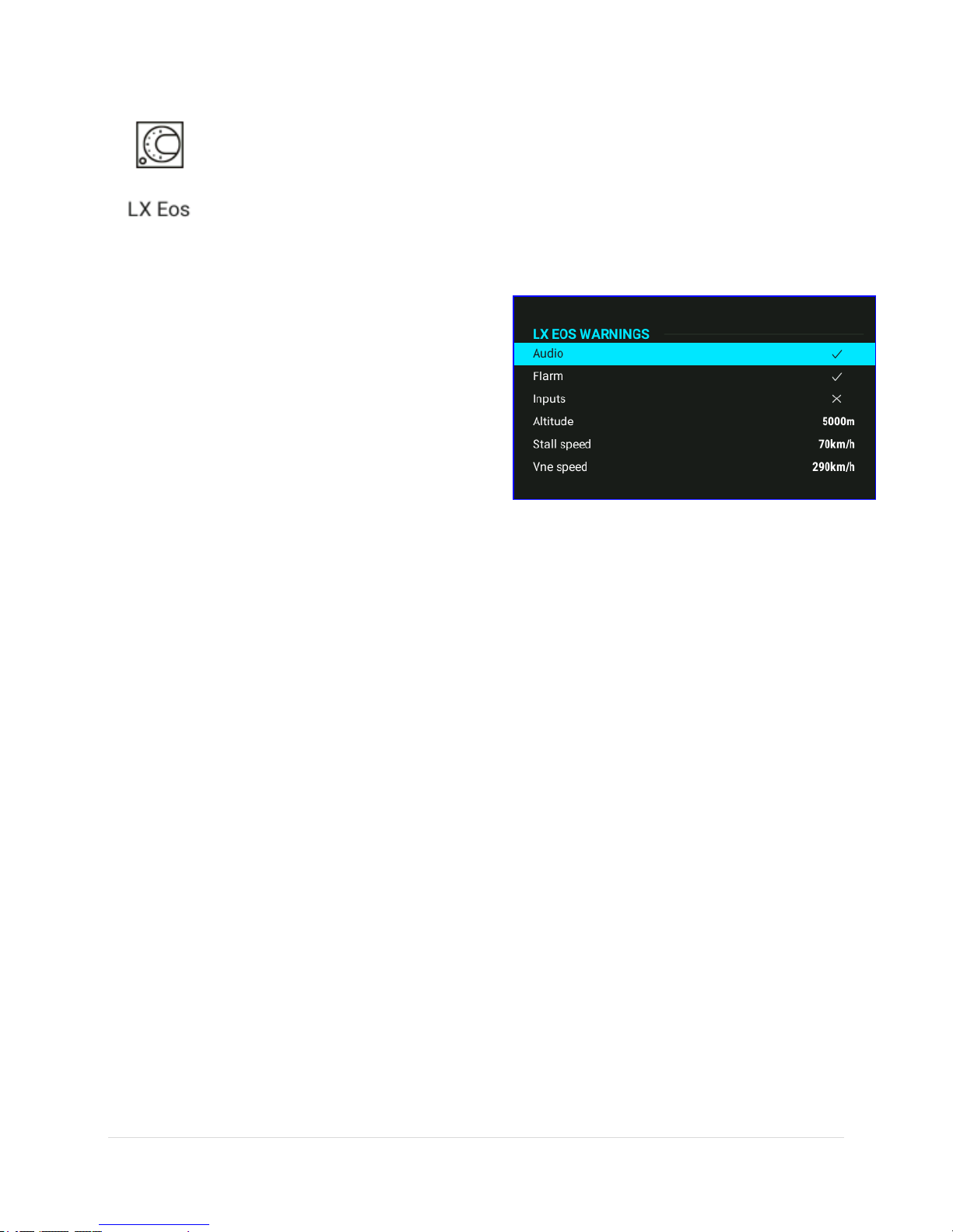
2.2.4 LX Eos
All settings for LX Eos are done on LX Zeus.
LX Eos settings appear only if LX Eos is connected to LX Zeus, otherwise, there are audio
settings for vario (see previous chapter for more information).
If the battery is too empty for the LX Zeus, the LX Eos will still work because it has an
internal battery. In this case, settings for LX Eos are set on the LX Eos device (for settings on LX Eos see LX
Eos manual)
Warnings
Warnings are used to inform the pilot that some flight
related data is outside the desired margins. When a LX
Eos detects a warning state, the pilot will get a red
warning message box with a description of what is
outside the margins.
By ticking the box the pilot can enable audio and Flarm
warnings.
o Audio: If disabled, voice warning will not be
generated – the only warning will be visual in
message box.
o Flarm: Flarm warning page will be seen only on
the Flarm radar page if this flag is disabled,
otherwise it will override any Eos page/menu
when a warning is detected.
o Inputs: Must be turned on to enable input port
warnings such as airbrakes, gear etc
o Altitude: Warning when flying above a selected
altitude.
o Stall speed: Warning when the glider speed is
lower than stall speed.
o Vne speed: Warning when speed exceeds Vne.
Audio
Variometer sound frequency can be changed.
Negative frequency means the frequency when the variometer indicates sink of -5.0 m/s (-10 kts).
Zero frequency is frequency when variometer indicates 0.0m/s.
Positive frequency is frequency when variometer indicates climb of 5.0 m/s (10 kts).
18 | P a g e
Page 20
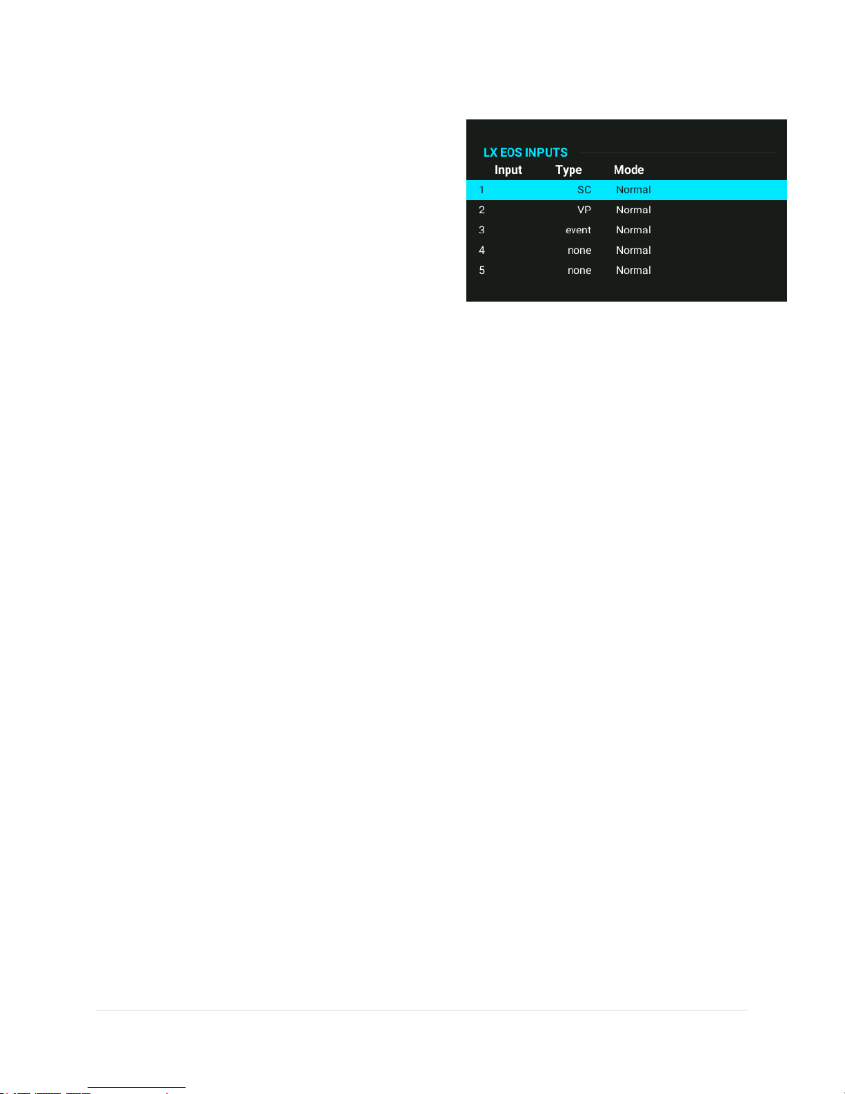
Inputs
LX Eos offers the possibility of five different user defined
inputs. Each input can be set accordingly.
There are seven options to choose from:
None: nothing is connected to the input.
SC: the device changes mode from vario to SC
mode
VP: (vario priority) the device goes to vario mode
no matter what the SC is selected to
Event: an event when a flight recorder is activated
and pilot gets a message shown on display
Gear: If enabled under warnings, warnings will be
generated such as gear up/down warnings after
takeoff / before landing
Airbrakes: if enabled under warnings, will
generate airbrakes warning if they are opened
during takeoff
LX Zeus v4.0.2
The pilot can also select if the switch is working in normal mode or if it is working in inverted mode. Normal
mode means that the switch is enabled when contact is closed, inverted means that switch is enabled
when contact is opened.
If two or more inputs are the same, the corresponding action will be made when all of them are active
(active = switch opened!). The answer as to how to connect switches to external switch interface, and
what “active state” is, can be found in the external switch installation section of LX Eos manual.
NMEA
This setup page is used to set what data is sent to a thirdparty unit connected through Bluetooth or USER port.
The pilot can set baud rate (BR) for communication
through the USER port or Flarm port.
The pilot can select from: BR4800, BR9600, BR19200,
BR38400, BR57600 and BR115200 options.
LX Eos is capable of sending NMEA data to third party
units such as PDAs or PNAs. The data is available on the
connector marked as USER and Bluetooth port. Five data
strings are offered. Selected (check box) NMEA data will
be sent over the USER port and Bluetooth:
GPGGA – Global Positioning System 3D-Fix Data
GPRMC – Recommended Minimum Specific
GPS/TRANSIT Data
GPRMB – TP navigation info
19 | P a g e
Page 21
LX Zeus v4.0.2
Note
When Radio option is enabled (KRT2 or ATR833) all other outputs on User port are disabled, but
are still present on Bluetooth port.
LXWPx – sentences contain pressure and altitude information in addition to IAS data
PFLAx – Flarm traffic info. Data must be enabled, if Flarm data is required on a PDA
Radio – Select which radio is connected to Eos USER port. KRT2 and ATR833 were tested and are
supported at the moment. Baud rate on USER port is automatically set to 9600
Pages
The pilot can select which main pages are active on LX Eos.
A page is active when its box is checked.
There are five main pages available:
TA (thermal assistance)
Flarm
TP (turnpoint)
TSK (task)
GPS info (basic GPS information)
AHRS (if AHRS module is connected)
2.2.5 Voice
In the case of LX Eos, or if LX Voice Module is a part of the system, the following settings can
be used: If Enable all or Disable all are pressed the pilot can enable / disable all voice
commands at once.
Volume:
Voice volume: defines volume of voice messages
Vario mixer: defines the balance of volume between Audio and Voice
General Information:
Enable or disable general information about pilot, glider and elevation
Task Information:
Enable or disable information about task, turn point, final glide and time
Warnings:
Enable or disable warnings
Flarm:
Enable or disable information about Flarm and warnings
20 | P a g e
Page 22

LX Zeus v4.0.2
2.2.6 Vario-SC
Settings in this menu define vario
characteristics and some other important
inputs connected to vario and speed
command.
Vario:
Vario filter defines the dynamics of the vario
needle. Lower number means faster reaction
and vice versa.
Integration time (displayed on vario unit)
The time period used for the integrator
Vario scale, three options (2.5, 5 and 10 m/s) (or
5, 10 and 20 kts, if selected in Units).
Other:
Silence range, defines range of no audio around
zero when in speed command
SC switching threshold, changeover speed at which it will change from Vario to SC if Automatic SC
switching is enabled
Automatic SC switching, defines speed parameters for automatic change over to SC
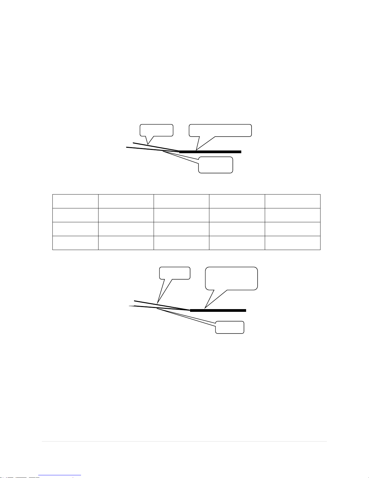
External switch mode*, determinates external SC switch status which change over to SC
*LX Zeus-LX Eos
Connect the external switch of input interface, which is connected to the input port on the rear of LX Eos.
It does not matter to which of the 5 inputs it is connected. Then go to the Setup page on Zeus and navigate
to LX Eos page. Next go to input and select one input as the SC option.
Next, go to Vario-SC setup:
Setting the External switch mode to ON means that closing the switch will enable SC mode, and setting
External switch mode to OFF means that closing the switch will select Vario mode. There is a third option
that can be enabled by setting External switch mode to Toggle and connecting a push button. Now each
press will toggle between SC and Vario (This is the obligatory setting when using the LX Remote or LX Joy).
21 | P a g e
Page 23
LX Zeus v4.0.2
Wire
Shield
Open
Setting: ON
Status: VARIO
Wire
Shield
Open
Setting: OFF
Status: SC
Wire
Shield
Closed
Setting: ON
Status: SC
Wire
Shield
Closed
Setting: OFF
Status: VARIO
Wire
SC marked
cable
Shield
Shield
*LX Zeus-USB D 60:
LX Zeus has a connection for an external speed command switch, which is wired to the vario unit (USB D
60). By using an external switch, it is possible to switch between SC and Vario manually. Setting the
External switch mode to ON means that closing the switch will enable SC mode, and setting External
switch mode to OFF means that closing the switch will select Vario mode. There is a third option that can
be enabled by setting External switch mode to Toggle and connecting a push button. Now each press will
toggle between SC and Vario (This is the obligatory setting when using the LX Remote).
22 | P a g e
Page 24
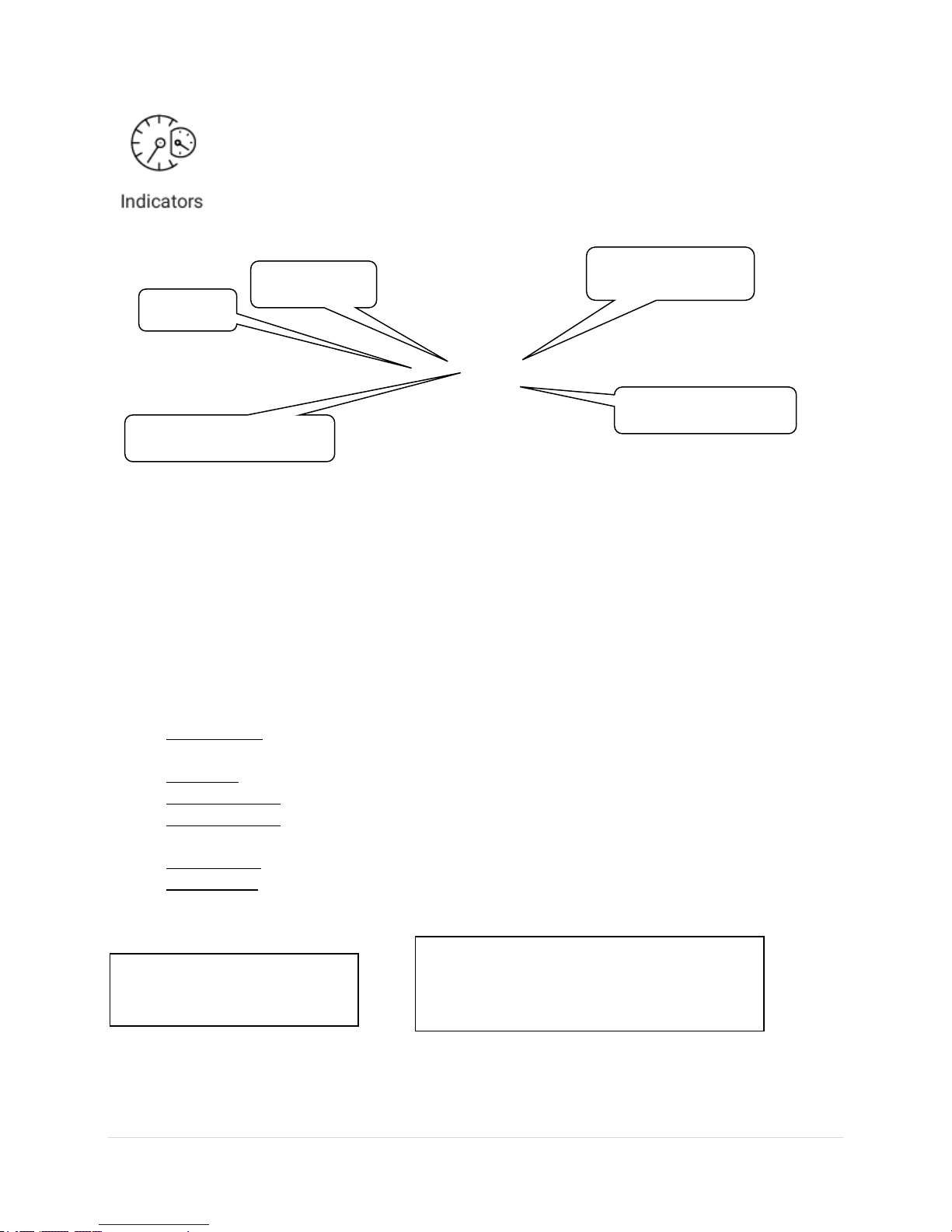
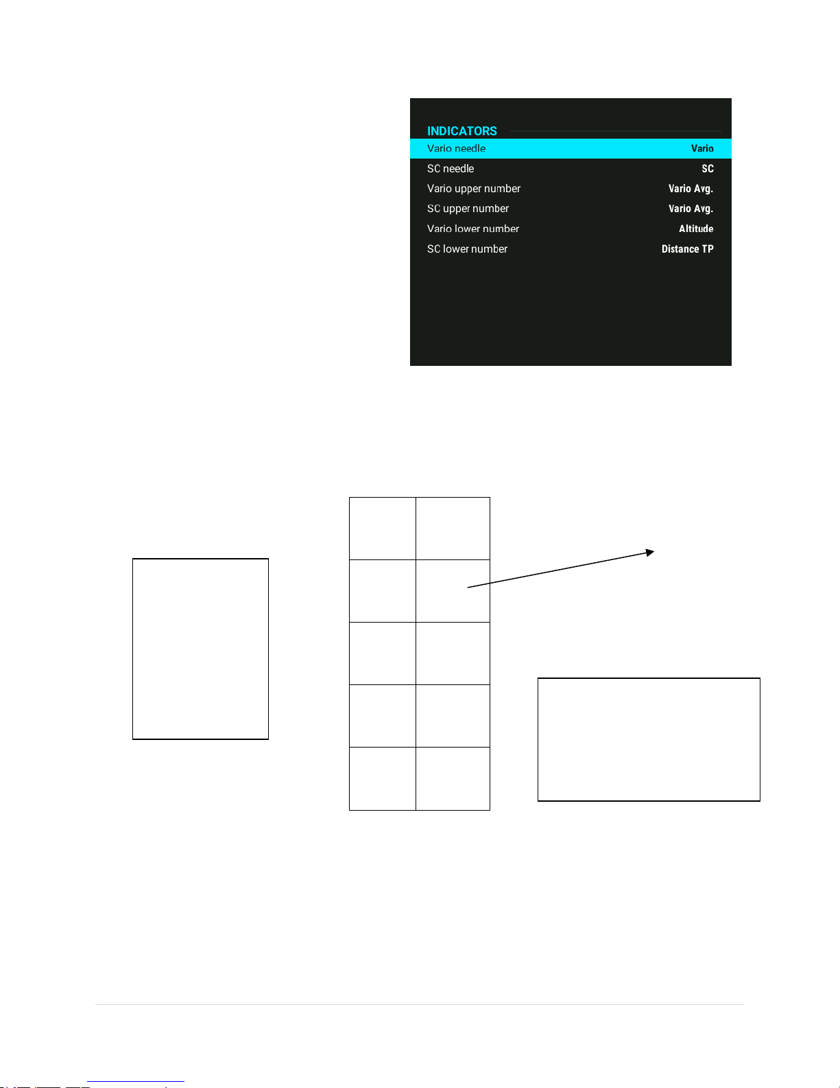
2.2.7 Indicators
Needle
SC* dot ind.
Needle status indicator
Lower num. indicator
Upper num.
* Vertical speed of air mass
** Vertical speed – 0.8 m/s
Note!
Setting Altitude QNH ft sets Altitude indication
in ft, no matter what is set in Units.
The indicators page is used for setting up varios with mechanical needles and colour
graphic displays. One indicator is defined as a variometer. The system is capable of driving
secondary indicators identified as ‘’Number 1’’ through to ‘‘Number 4’’. For LX Eos
repeater, connect it to Lx Zeus second seat CAN bus port.
LX Zeus v4.0.2
In general, every indicator consists of a mechanical needle, SC dot, needle status indicator, upper/lower
digital indicator, battery indicator and a GPS signal indicator. It is important to point out that the settings
should be done separately for vario and SC mode of operation. A radial moving dot serves as a continuous
speed to fly indicator; this cannot be changed. On the LX Eos, there is a radial moving arc that serves as a
speed to fly indicator. Additionally, there are GS (ground speed) and wind indications, plus some other
status icons (Flarm, Bluetooth, etc.) which cannot be changed.
Used terms explanations:
Vario needle: means the needle function in vario mode, alternatives are: vario, Netto*, SC,
Relative**
SC needle: means the needle function in SC mode, alternatives are: Netto, Relative, Vario
Vario upper No.: means the display indication with option of: integrator, time, flight time, leg time
Vario lower No.: means the display indication with option of: altitude, distance, glide difference,
true air speed, leg speed, QNH, flight level
SC upper No.: means the display indication with option of: integrator, time, flight time, leg time
SC lower No.: means the display indication with option of: altitude, distance, glide difference, true
air speed, leg speed, QNH and flight level
23 | P a g e
Page 25
LX Zeus v4.0.2
Number
Switch
IND 1
x x
IND 2
x
x
IND 3
x
x
IND 4
x x
Note!
Indicators installed for the
second seat should be connected
to front seat with 485 bus
Note!
Units having Adr1
will simply repeat
what is displayed
on the vario.
Higher addresses
make different
settings possible.
2.2.7.1 Secondary indicators
Secondary indicators should be connected via the 485-system bus; there are three 9P connectors at the
back of the unit. All contacts are in parallel so it doesn’t matter which one is occupied. The unit can be also
used as a 485-system bus splitter. To define indicator number use DIP switches which you find at the back
of the unit.
Once indicator functions have been defined, switch the unit off and then on again, this procedure will
memorize the settings and it will then be possible to adjust the settings on LX Zeus.
24 | P a g e
Page 26

2.2.8 Flarm
This menu is used for changing the Flarm
visualisation parameters. The only executive
command which can be sent to Flarm unit is
privacy mode.
Activation of privacy mode will send the Flarm unit into
“stealth mode”, which means that the data transmitted
to and from Flarm unit is limited.
Others commands are:
Show objects till zoom defines the distance at
which a Flarm object appears on the map
Rel. altitude interval sets the altitude difference
for a Flarm object to appear
Glider icon size
Airliner icon size (any powered aircraft)
Show Flarm tails
Tail colour
Tail width
Use above/below colour coding (makes it possible
to define the colour for above and below Flarm
objects)
LX Zeus v4.0.2
25 | P a g e
Page 27
2.2.9 Logger
Note!
Pilot and glider data are sent after task Declaration process has been executed. See section Flying.
LX Zeus uses LX Eos and/or Colibri II as an IGC
approved flight recorder. Both units
collaborate so that all necessary settings can
be sent to all flight recorders connected to the
system (LX Eos, Colibri II). No action is required on LX Eos
and Colibri II when flight recorders are connected to LX
Zeus.
Recording interval is set to 5 seconds by default. Event
repetitions are set to 20 and event fix interval to 1 second.
This means that when press “Event” button is executed
the logger will create 20 records in 20 seconds (one per
second).
The extra recording option means that you can select the
recording of Ground speed into log file.
LX Zeus v4.0.2
This menu is usable only if LX Eos and/or Colibri II is
connected to LX Zeus. If settings are changed, they will
not affect Flarm IGC or any other connected Flight
recorder.
In a double seat configuration, the second seat pilot is also able to change flight recorder settings. The
process is the same as for the first seat.
26 | P a g e
Page 28
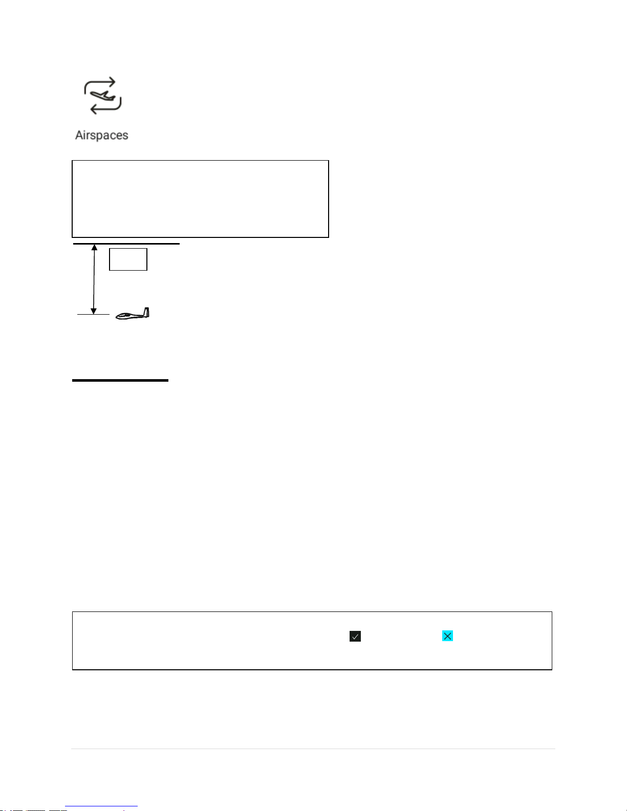
Note!
Hide above airplane option will remove airspace
sections which are higher than the setting. This will
reduce the clutter on the graphic page significantly.
1000
Show on zoom, defines appearance of particular airspace sections on the display. Appearance is
connected to zoom. Airspace warning can be set as active ( ) or as not active ( ).
LX Zeus v4.0.2
2.2.10 Airspace
All settings connected to Airspace
management are available in this menu.
Example of Hide airspace above:
• The maximum vertical and horizontal distance
to which airspace in Airspace info box on map
is displayed can be set. If there isn't any
airspace that fulfil these conditions the
Airspace info box will not appear
• Hide above QNH altitude to disable airspace that is above set QNH altitude
• Audio warnings (on vario) when airspace warning appears on the LX Zeus can be dismissed
(dismiss buttons)
Default warnings for airspace are set to 2 km horizontally and 100 m vertically but these warning settings
can be adjusted. Warning timeout at takeoff is pre-set to 5 minutes, which means, that during the first 5
minutes after takeoff there will not be any airspace warnings.
27 | P a g e
Page 29

LX Zeus v4.0.2
2.2.11 Wind
LX Zeus is able to measure wind
using different methods; these can
be selected in the Wind menu.
Wind calculation results are shown
as a standalone indicator on the
main graphic page and also as a NavBox, if set.
The pilot can choose between two circling
methods: one which measures wind during circling
flight and the second method using straight flight.
The wind calculation is used for numerous
calculations (TDT, Final glide, etc.).
2.2.11.1 Circling model
Speed difference is based on the variation of ground speed (GS) using the wind detected whilst in
circling flight. This method is only active during circling. (In straight flight the wind data remains
unchanged). The process is started automatically once circling is detected. After two circles the
wind indication (direction and speed) will be updated and displayed. This method is based on the
ground speed being affected by the wind. GS is, of course, at its maximum with a tailwind and
minimum with a head wind and this is used for the GS difference calculation method. To get a
result the pilot should do two turns as a minimum, more turns will improve the result. Please note
that up to 90 degrees turn or more is required as some time is needed to detect circling status. It
is important to keep constant IAS speed during circling. However, other factors are also taken
into account to cancel out the fluctuations of airspeed while circling. This wind calculation method
is the default and preferred approach.
Position drift calculates wind regarding to position change during circling. Such a method needs
more circles than speed difference (from 4 up to 8). The number of circles should be set in Drift
circles option. If both methods, straight model and position drift are selected, the Zeus will give a
combined result.
2.2.11.2 Straight model
None: If you select none, you will have the wind from the latest circling method.
Iterative: This method will update the wind in straight flight. It is a special method developed by
LX Navigation and delivers accurate wind measurements by using sophisticated algorithms. With
this method, you do not need a compass. The pilot will, however, get good wind speed and
direction results. This method does not supplement Head/Tail method and, for best results, a
constant IAS is required.
Compass: The Compass system requires the compass module to be connected to the unit using
the 485 bus or CAN bus. Wind calculation is based on the wind triangle method. Under this
approach, airspeed, ground speed and wind create a triangle of vectors. A compass device offers
magnetic heading, which defines the direction of the airspeed vector. To measure wind using a
compass straight flight speed and direction must be kept as stable as possible.
28 | P a g e
Page 30

LX Zeus v4.0.2
*Compass module is a standalone electronic device, which
can be connected to LX Zeus via 485 bus (or CAN bus for
newer versions.) The unit delivers the magnetic track to the
LX Zeus. However, to get accurate measurements, it is
essential to have good compass calibration.
Note:
Compass option is available
only if the compass module is
connected.
Head/Tail: Shows difference between GS and IAS.
Time for straight flight: Time in seconds that will be taken for one measurement (valid for straight
model). The longer the period the better the result. This is valid only for the compass method and
not for the Head/Tail one.
Drift circles: Sets how many circles are required to calculate the position drift.
Compass assistant: Is a special symbol that appears on the display and helps to keep flight
parameters (speed and direction) stable during calculation.
2.2.11.3 Manual wind settings
Set manually - manual wind speed and direction can be set which will be displayed and used for
all calculations.
2.2.11.4 Influence of wind in final glide
The actual wind data (speed and direction) influences the final glide calculation. In task mode the final
glide indication is based on the remaining distance over all TPs until the finish (not over turn points already
overflown). Wind influence for individual legs is based on actual wind data. Using the Head/Tail method
will define wind direction on actual track being flown and this value will be taken into final glide calculation.
2.2.12 Task
The Task menu allows the setting of
default zones for quicker and easier
task creation.
Under Other settings can be set:
- TDT calculation sets the task delta
time calculation method
- AAT calculation sets whether the
next TP is set automatically or by hand
- Task start navigation sets the point
to which your glider computer will
navigate
- Sync with TP navigation sets the
same turnpoint for Task and TP menu
29 | P a g e
Page 31

2.2.13 User interface
In the User interface menu, the
pilot can adjust most of the
graphic options apart from layout,
which has its own menu. All
settings are saved to currently selected pilot profile.
2.2.13.1 Map settings
All settings regarding map appearance (map palette
colours, glider image, orientation, distance circles etc.)
can be adjusted in the Map settings menu.
The pilot can select the zoom level used once circling
has been detected under the field At circling switch to.
Map palette
The Map palette menu is used for adjusting colour
schemes used for terrain display on the map.
LX Zeus v4.0.2
Personal colour schemes can be created.
The last option allows the disabling of map appearance
features, which is useful in situations when only
airspace and task data is required.
The map can be temporarily disabled under shortcuts
(long press on Zoom rotary knob).
Glider image
Glider image icon can be sized and colourized by
choice.
Default:
Colour white
Size 25 (maximum size can be 60)
Map Orientation
The map orientation of LX Zeus can be used in three
different ways:
Track up: Glider always points to the top of the
screen
North up: North is always on the top of the
screen
Track circ. North: Combination of track up and
north up related to flight status (circling,
straight flight)
30 | P a g e
Page 32

Distance circles
Note: Range is displayed only in TP and APT view.
In this section, it is possible to select the number, size
and colour of distance circles on the map. Distance
circles are a useful tool for getting a feel about the
distance to certain objects on the map.
Range (graphic glide reach)
Activating this feature shows the glide range curve
from the current position in all directions. It uses wind,
terrain and glider data to calculate the end result.
Show range from zoom defines from which zoom level
the glide range is available. (If set on Never - function
will be inactive)
Next three settings are connected to fill colour,
outline colour and outline width.
LX Zeus v4.0.2
Range is calculated and displayed by using the
following parameters:
Reserve altitude
Glider polar
MC
Ballast
Bugs
Elevation
Wind
2.2.13.2 Fonts
The font system is fully adjustable:
Cities on map (default 15px)
If this is set to 0px, there will be no city names
on the map
Turnpoint on map (default 15px)
Airports on map (default 15px)
Flarm objects on map (default 17px)
Distance circles on map (15px)
NavBox line (default 30px)
Header (default 24px)
31 | P a g e
Page 33

LX Zeus v4.0.2
2.2.13.3 TP/APT settings
In this menu, the appearance and length of TP and
APT labels on the map can be adjusted at different
zoom levels:
Show TP till zoom: Adjust visibility of TP at
given zoom
Show TP labels till zoom: Adjust visibility of
TP labels at given zoom
TP labels length: Set number of label
characters shown on the map
TP label colour: Select label colour
Hide turn-points near APT
Draw specialized icons
Specialized icons size
Show APT till zoom: Adjust visibility of APT
at given zoom
Show APT labels till zoom: Adjust visibility of APT labels at given zoom
APT labels length: Adjust the number of label characters shown on the map, ICAO code can be
selected
APT label colour: Select label colour
2.2.13.4 Task settings
This menu is used for personalizing start, finish and
turn-point lines/zones. It is also possible to change
their outline colours, fills and outline widths.
Show equidistant lines is a neat feature which
enables the pilot to know in which direction no
speed is being gained in an AAT zone. It is always
best to fly perpendicular to the lines.
Default task colours:
Active zone: Pink
Active start/finish line: Red
Inactive zone: Cyan
Inactive start/finish line: Teal
Legs yet to cover: Royal blue
Active leg: Yellow
Covered leg: Green
Course to next TP: Cyan
Transparency can be set for all colours.
32 | P a g e
Page 34

2.2.13.5 Airspace
The colours and width of airspace sections to meet
personal preferences can be set.
Default colours are:
Selected/active airspace: Blue
Controlled area: Red
Prohibited area: Red
All other: Blue
2.2.13.6 Tail settings
This page is used for adjusting the tail parameters.
Draw tail for last setting is used for determining
how long the tail should be.
LX Zeus v4.0.2
Vario colour-coding setting allows the pilot to
enable or disable colour-coding. If this function is
disabled, it is still possible to choose the colour for
the tail.
ENL colour is displayed when the flight recorder
detects the engine is running.
If a grey (default colour) line as the tail is seen, and
the engine is not running, please check that the
flight recorder is not positioned in such a way that the
noise from ventilation or an open window is not causing
the issue.
Default vario tail colours are:
Negative: Blue
Zero: White
Positive: Red
ENL: Dark grey
The width of the tail depends on the strength of the thermal in that moment.
The stronger the thermal, the wider the tail. The default tail width is 10px (2 pixels per 1m/s)
33 | P a g e
Page 35

2.2.13.7 Track/destination settings
Track colour shows the vector of current
movement. The default colour is green. It
can be changed by setting the transparency
to 100%.
Track to destination colour page sets the
colour of the vector line that connects the
glider with the destination point. Default
track colour is Cyan.
2.2.13.8 Thermals
This page is used for setting the thermal icon
parameters. The Thermal icon will show where the
glider has circled and what the average thermal
strength was.
The Zoom level can be selected for showing at which
it will show the colour coding as well as the minimum
avg. vario strength and minimum altitude gained so it doesn’t show every turn.
LX Zeus v4.0.2
2.2.13.9 Subpage 3
Subpage number 3 can be enabled or disabled.
It can set so that it only shows a 3D view or a 3D view + map.
2.2.13.10 Auto close inactivity time out
LX Zeus monitors the push buttons and rotary knobs during the editing process. If no action is detected
the program will change back to the previously used navigation page after a predefined time period. The
time is flexible and can be chosen in a range from 6 to 60 seconds. It is also possible to disable the auto
close function. If the time is set to off, than the page will disappear only if the Volume rotary knob is
pressed (“escape” / ”go back” button). The default time is 30 seconds.
34 | P a g e
Page 36

LX Zeus v4.0.2
2.2.13.11 Layout
The LX Zeus home screen can be customised. Which NavBoxes are shown can be changed
as well as their size, order and where they are placed. The same can be done with the map
as well as other indicators.
2.2.13.12 Layout edit procedure:
Go to setup / Layout
Press Zoom rotary knob on
Layout
Check which panels are to be
edited (TP, APT, TSK)
Rotate zoom rotary knob to select
Edit and press Zoom rotary knob.
Press the Edit layout button
Main screen will open with a blue frame
(blue frame shows what has been selected,
eg: map, NavBox container or another indicator)
Select the indicator, NavBox container or map to be edited by rotating the Zoom rotary knob (the
current selection will be displayed with a frame around the selected indicator)
35 | P a g e
Page 37

Moving and resizing
Note!
After saving the new layout it may appear that nothing changed on the screen, this is because you
are at the wrong navigation screen (if you changed the TP and you are in the APT screen then it
seems that nothing has changed). Press an APT button to select the customized screen.
How to move selected element:
Select indicator to be moved
Short press Zoom rotary knob (a large cursor
symbol will appear in the middle of the
indicator)
Use Zoom and Volume rotary knob to move the
indicator
Press Zoom rotary knob to stop the move
procedure and start the resize procedure
How to resize (expand or compress):
Next press the Zoom rotary knob and it 1will
open a similar window but now with a cross
through the selected indicator.
Use Zoom and Volume rotary knobs to resize it.
Press Zoom rotary knob to stop the resizing
process.
LX Zeus v4.0.2
The customisation process terminates when the
Volume rotary knob is pressed.
(layout saved message will appear)
36 | P a g e
Page 38

Note!
To escape from Edit Background colour menu
you don’t necessarily have to press Volume
rotary knob, you can simply wait 15 seconds
and the screen will go back to the first
(Properties/actions) menu.
2.2.13.12.1 Selecting/Deselecting and editing
Selected indicator to be
customized
Changing the background colour of
indicators
Editing process:
Select the indicator to be customized (a blue
frame will appear).
LONG press the Zoom rotary knob (if a long press
is not made then there will still be an option to
move or resize it)
Select the colour to be changed (rotate Zoom
rotary knob) and give a SHORT press of the Zoom
rotary knob - a new window (Edit Background
colour) will open
Now the colour can be changed simply by picking
one from the palette and pressing the Zoom
rotary knob. If one has been picked from the
palette, but transparency is required, just go back
again. Edit Background colour window (press
Zoom) and go to transparency (press Zoom)
LX Zeus v4.0.2
Rotate Zoom rotary knob to set the transparency
required, confirm it by pressing Zoom rotary
knob and then pressing Volume to escape.
To terminate the customization process, press
the Volume rotary knob once to escape from Edit
Background menu and then again press the
Volume rotary knob to escape from
Properties/Actions menu. An edited indicator will
appear on the screen that you have customized
37 | P a g e
Page 39

Selecting/deselecting process:
Selected Header
indicator
Go to Setup > Layout, press Zoom rotary knob,
select the screen to be edited and go to Edit (press
Zoom rotary knob)
Make a LONG press on Zoom rotary knob and the
window Properties/Actions will open
Edit flight map properties
Select row: Select Indicators and press Zoom
rotary knob and a window Select indicators for
chosen panels will open
Now select/deselect indicators that are not
wanted on the screen. Select and deselect them
by rotating and pressing the Zoom rotary knob
To get out of edit mode, press Volume rotary
knob and the selected indicator will appear on the
screen
LX Zeus v4.0.2
38 | P a g e
Page 40

Note!
Restore to default will
restore back to factory
settings.
Map and NavBox container
are not indicators.
Properties/Actions window
This window is activated by a LONG press of the Zoom
rotary knob. In this window, colours can be adjusted for
the selected indicator as well as other setting such as:
Number of rows for NavBox container
Scale size for Sliding speed indicator
By selecting one of the Action rows one can:
Select indicators to be seen on the screen
Restore the layout to default settings
Continue with editing indicators
Save layout and exit with new settings
LX Zeus v4.0.2
Indicators
The following indicators can be selected:
Header – upper row
Speed indicator – IAS
Sliding speed indicator – not the whole IAS – the
scale that is displayed can be customised
Classic (circular) speed indicator
Variometer – sliding variometer
Variometer classic – rounded variometer
Wind indicator – shows direction and speed
Final glide indicator (selected MC)
Final glide indicator (MC 0.0)
Thermal assistant
Compass – rounded compass
Compass needle
Compass assistant
Airspace info
Limitations (start conditions)
Map scale
AHRS
Flap position
Flarm indicator
Best alternate APT info
39 | P a g e
Page 41

LX Zeus v4.0.2
Map – NavBox container transparency
If it is required to have a NavBox container transparent, then the map should be stretched over the whole
screen and background colour for the NavBox container should be set to transparent.
2.2.13.13 Copy NavBoxes
The whole NavBox container can be copied from one panel to another (TP/APT/TSK) via Layout. Always
prepare NavBoxes on one panel to be used as a reference for other panels. Once a reference panel is
selected, should check the destination panels into which NavBoxes are to be copied. After that, select Copy
from `reference` to `destination` to complete the procedure.
2.2.13.14 Copy layout
Copy of one layout can be copied to one or both remaining
screens.
Under Reference panel choose the layout to be copied.
Under Destination panels choose which layout to copy the
reference layout to. After selection press Copy from
reference to destination to complete the procedure. A
green message will appear to confirm that the layout was
successfully copied and saved.
2.2.13.15 NavBox as indicator
A NavBox as an indicator can be added to the map. There is
no limitation on the quantity of NavBox indicators on the
map. Each NavBox can be customized (different colour,
transparency, size, position).
Procedure for adding new NavBox indicators:
Go to Layout and select the screen to be adjusted,
press EDIT
A long press on Zoom rotary knob will open the
Properties/Actions window
Move down to “Add NavBox indicator” and select
this line with a short press on the Zoom rotary knob
A list of all available NavBoxes will appear. Select the
NavBox required and position it on the map in the
same way as moving/resizing other indicators
Procedure for removing NavBox indicators:
Go to Layout and select the screen to be adjusted,
press EDIT
A long press on the Zoom rotary knob will open a
Properties/Actions window
Select “Remove “xy” NavBox”
40 | P a g e
Page 42

LX Zeus v4.0.2
2.3 System Setup
The parameters set in this section are valid for all pilots (and are not saved to a specific user profile).
2.3.1 Units
A large selection of units can be defined in
this menu.
Units can be defined for: Altitude, Vario (rate
of climb), Speed, Task speed, Wind speed,
Distance, Pressure, Temperature, and Mass.
Pre-set metric, imperial or UK units can be set.
2.3.2 Glider
Nearly all glider polars are stored in the LX
Zeus memory. In addition to these standard
polars it is possible to create custom polars
by changing the parameters.
In the glider menu, it is possible to set all glider related
information, such as:
Competition ID
Equipment weight
Active Polar
Speed indicator settings
Flap position settings
TE level (not possible from second seat unit)
TE filter
Registration number
41 | P a g e
Page 43

2.3.2.1 Creating a user defined polar
In Setup > Glider select Active polar. Enter the required
polar parameters.
A, B, C parameters can be calculated the LXe PC program,
or the built-in calculator described below can be used.
Calculating A, B and C constants
To calculate A, B and C parameters, follow these steps:
Setup > Glider Active polar > Select glider > User
defined.
Now press the Calc. A, B, C button. Then enter
Tobtained from the glider polar or from other data
sources. Be aware that the most important
parameter is reference weight. For different
reference weights the numbers will differ.
To use these parameters select Use calculated
parameters.
LX Zeus v4.0.2
3 default polars can be set under Active polar which will appear once the Zeus is turned on. This feature is
especially useful for a glider with variable wing span.
2.3.2.2 Speed indicator settings
The speed markings of the sliding IAS indicator colours on
the Zeus can be adjusted.
2.3.2.3 Flaps position settings
For gliders with flaps, Zeus offers an indicator that will
remind the pilot to change flaps to the recommended
position. The speeds and position numbers must be
defined. Recommended flaps position is available as an
indicator in Layout (Flap position indicator) or as a NavBox
(Recommended flap position). If a Flaps sensor is
connected to the CAN bus then please check the
calibration procedure below. Using sensors enables the
current flap position to be shown alongside the
recommended position. This information is available as an
Indicator, NavBox and on a stand-alone LX NavBox device
connected to the CAN bus.
42 | P a g e
Page 44

2.3.2.4 Flap sensor calibration
FILTER
0.2 to 5
RAW VARIO
FILTERED VARIO
INDICATION
If a LX Flap Sensor is connected to the CAN bus it is
possible to show the current flap position together with
the recommended flap position. Connect the LX CANAD to
the CAN bus and insert two wires from the flap sensor to
LX CANAD inputs (recommended is IN1). Open the Flaps
position settings dialog on LX Zeus. First select the channel
where the Flap sensor is connected to LX CANAD (default
is IN1). Next move the Flap lever and check that Lever
position changes values; this means that the Flap sensor
has been properly connected to the system. Now the
calibration procedure can be commenced:
- Put the flap lever to aft position (landing or most
positive).
- With Zoom rotary knob select the first line.
- Start editing this line:
o Insert position name (up to 4 characters).
o Select minimum speed for this flap
position.
o Select maximum speed for this flap
position.
o Press Save screen button to save settings
for this line.
- Move the lever to next position and repeat
procedure until all positions have been covered.
- Exit this dialog to send the new settings to LX
Flaps Sensor.
LX Zeus v4.0.2
2.3.2.5 Total Energy (TE) level and filter
There are 2 ways of providing TE for the LX Zeus; either tube or electronic compensation.
TE level***, set TE compensation style, 0% for TE tube compensation.
TE filter***, only valid for electronic TE compensation.
The LX system incorporates a configurable electronic filter. This filter adjusts the time constant and is
adjustable between 0.2 and 5 seconds. The 0.2 setting is the fastest while the 5 setting provides maximum
damping.
43 | P a g e
Page 45

LX Zeus v4.0.2
Note!
Electronic and pneumatic TE compensation requires
different tube connections.
In more detail:
Pneumatic compensation
The method used is determined by the % figure set for compensation as well as the way in which the
pneumatic tubes are connected. If compensation by using a TE probe is required, then set the % figure at
0%. With this method, the Zeus will not process any electronic compensation and will use only the TE
source.
When using pneumatic compensation using a TE probe, the accuracy of the TE compensation depends
entirely on the location, size and quality of the TE tube. The installation must be leak-proof.
Electronic TE compensation
Electronic TE compensation is activated when a % setting of more than zero is selected. When this is done
a software routine is activated and the system will provide TE compensation. The default value is 100%
but this can be adjusted by test flying and-fine tuning the setting to deliver the optimum compensation.
Electronic TE compensation can be fine-tuned during flight using the procedure set out below. It is
essential that this is only done in smooth air as it is not possible to tune the TE accurately when there is a
lot of thermal activity.
Select 100 % and default TEF (TE filter).
Accelerate up to approximately 160 km/h (75 kts) and keep the speed stable for a few seconds.
Gently reduce the speed to 80 km/h (45 kts).
Observe the vario indicator during the manoeuvre. At 160 km/h (75 Knots) the vario will indicate about -2
m/s (-4kts). During the speed reduction, the vario should move towards zero and should never exceed zero
(slightly positive indications are acceptable). If the vario shows a climb, then the compensation is too low,
increase the TE%; and vice versa. Repeat this procedure and make further adjustments as necessary.
Electronic TE is only effective when the Ptot and Pstatic sources are co-located and the pneumatic lines to
the instrument are approximately the same length. The best sensor to use is the combined Ptot/Pstatic
Prandtl- type tube. If problems are experienced with the electronic TE compensation, then the most likely
cause is the glider's static source. The static source can be checked by changing the connection of the
pneumatic tubes for electronic compensation, and then setting the TE: to 0%. In still air, and as explained
above, accelerate to approximately 160 km/h (75 Knots) and reduce the speed. Observe the vario
indicator. If the static source is good, then the vario should immediately start to move showing a climb. If
the needle initially shows increased sink and then moves to a climb, the static source of the glider is
unsuitable and there is no way to provide successful TE compensation electronically. The use of a
dedicated and accurate fin mounted Ptot/Pstatic source, such as a Prandtl tube, will be the only solution
in such cases.
44 | P a g e
Page 46

LX Zeus v4.0.2
TE (Pst)
vario
Note!
If electronic TE compensation is selected, then the TE (Pst) port should be connected to a good static
pressure source. If pneumatic compensation is selected, then the TE (Pst) port should be connected to
the TE probe.
port on
Compensation with TE probe Electronic compensation
Note!
Check LX Eos user manual for proper installation.
45 | P a g e
Page 47

LX Zeus v4.0.2
2.3.3 Checklist
Checklists are available under Setup > Checklist or by a long press of the SUBP button.
Once a checklist is open, keep pressing the Zoom rotary knob to complete the written
actions as per the checklist.
To create a new checklist, got to the Checklist menu and click New. After writing the checklist name,
choose the Edit button to edit name or Edit list to write the list itself.
A checklist can also be created on a computer which should be quicker. It can be imported via USB key to
the LX Zeus. To import/export a checklist go to Setup>Transfer>Checklist. Use Check list editor software
for LX Zeus available free on www.lxnavigation.com under the software section.
46 | P a g e
Page 48

2.3.4 Notepad
In the Notepad menu, a bespoke .txt file
with whatever content is required can be
prepared. Checklists, notes, input
frequencies etc. can all be included
.txt files can be uploaded with the USB stick by pressing the
screen button LOAD (button SELECT/NEAR). Notes can be
also written directly into the LX Zeus by using the Zoom and
Volume rotary knobs.
Screen button MODE is used to change between
uppercase letters, lowercase letters, numbers,
symbols, navigate etc.
Using NAVIGATE enables moving the text by using
both rotary switches. Characters can be deleted by
pressing the Volume rotary knob. To confirm the
written text, press mode, change to symbols, find
enter symbol and then confirm it by pressing Zoom
rotary knob.
Screen button METHOD is used to change
between `replace` and `insert` characters into the
written text.
Copy to USB is used to copy a current note to USB
stick and the file will appear on the stick in .txt
format.
Load is to upload .txt file from USB stick.
Save & Exit – is used to save the current notes and
also exit back to the setup menu.
LX Zeus v4.0.2
2.3.5 Transfer
The only way to transfer data from and to
LX Zeus is via USB stick. Any regular
regular USB stick formatted in FAT file
system format can be used. One such USB
stick is delivered with each LX Zeus and is
already formatted. (use a slim USB stick for LX Zeus 2.8).
After selecting the item of interest, by a press on the
Zoom rotary knob, the procedure will start.
47 | P a g e
Page 49

The transfer procedure is as follows:
Important!
Only one .af file can be active at a
time. After the transfer has finished
you should activate using Select
function. A green check means the file
is active.
Note!
The first TP file is also called TASK file,
which means, if you want to import
tasks from file, that you have to select
your file at TP/Task/Eos. This file is also
sent to LX Eos. In backup mode, you can
use points from this file to navigate.
Note that only the first 1000 points are
sent to LX Eos.
Insert USB stick
Press SETUP button
Select Transfer
Press Zoom rotary knob
Select what is to be transferred (example
airfields), and press Zoom rotary knob
Select “transfer file from USB” and press the
Zoom rotary knob
Example: all .af files stored on the USB stick will
be shown
Select the file of interest and press on the Zoom
rotary knob
The transfer will follow and a window and a green
check will show
Go to Select, press Zoom rotary knob and select
the file
The file is now activated (green check at select
row)
LX Zeus v4.0.2
How to delete files (APT, TP, AS):
Files can be removed from the LX Zeus using the Delete
internal files command. The command is executable for
Airports, Turn points and Airspace.
2.3.5.1 Transfer Airport data
The airport database in .af format for the Zeus is at
webpage www.lxnavigation.com. It is free of charge with
no code required.
2.3.5.2 Transfer Turnpoint data
The turnpoint data should be included in a file with
extension .cup or .cupx.
Three TP files can be active at the same time. Turn-points
of any of the three files will be available for navigation
without any limitations.
Transfer specific tasks
Tasks can be uploaded to Zeus via a USB key.
48 | P a g e
Page 50

To transfer a specific task, follow these steps:
o Export:
Insert USB stick
Press TSK button and select Save to USB. This
will save the task which is active in .cup
format, together with turn-points used in this
tasks
Remove USB stick
o Import:
Insert USB stick
Press SETUP button and go to Transfer
Go to Turn-points/Tasks (.cup, .cupx)
Go to transfer file from USB
Select the intended task
Go to the TP/Task/Eos file window and
activate the intended task
Transfer all tasks
This is used to transfer all tasks from one LX Zeus to
another
LX Zeus device.
LX Zeus v4.0.2
o Export:
Insert USB stick
Press SETUP button and go to Transfer
Go to Tasks on Zeus (.tsk)
Select Save all tasks to USB (this will save all
tasks as one file in .tsk format)
Remove USB
o Import
Insert USB
Press SETUP button and go to Transfer
Go to task on Zeus (.tsk)
Select Copy all tasks from USB
This is valid only for Tasks made on LX Zeus, tasks made on SeeYou or Strepla have to be uploaded as
TP (TP/Task file) using .cup format.
2.3.5.3 Transfer Airspace files
To transfer airspace data, use the Airspace option in the Transfer menu. The files should be in .cub, .sua
or OpenTXT format. The latest known airspace data is available free on www.lxnavigation.com. The
airspace files normally cover the whole continent.
Three airspace sections can be active at the same time. Special event airspace, such as for competitions,
can also be loaded.
49 | P a g e
Page 51

LX Zeus v4.0.2
2.3.5.4 Transfer Flarmnet files
Files with extension .fln include Flarm customized IDs and some added data about flarm objects which
makes it possible to identify gliders in the vicinity with their original IDs (usually competition ID). The file
is available on http://www.flarmnet.org
2.3.5.5 Transfer Charts
ICAO charts can also be used on the LX Zeus. The file for
the charts has to be .ras format. The ICAO charts can be
activated after importing a license file which must be
purchased from LX Navigation. The license file should be
transferred via USB stick.
A chart license can be transferred by going to Charts and
selecting Transfer licence from USB. Current charts can be
checked and deleted in the same window.
LX Navigation supports ICAO charts from Deutsche
Flugsicherung and Rogers Data.
2.3.5.6 Transfer Checklist
Checklists can be prepared on a personal computer using the special PC software available free from the
LX Navigation website. Files must be written in .xml format. They can be uploaded into LX Zeus by
choosing Checklist (.xml) in this menu. It is also possible to transfer checklists from LX Zeus to USB.
2.3.5.7 Transfer Logbook
Flights can be transferred from the Logbook under the
Statistics page or from this menu.
2.3.5.8 Transfer translation files
A file can be translated via special software from LX
Navigation (free on request). Once a file is completed it can
be transferred into LX Zeus using this menu.
2.3.5.9 System settings
This option should be used to transfer the complete system
settings from one Zeus to another.
50 | P a g e
Page 52
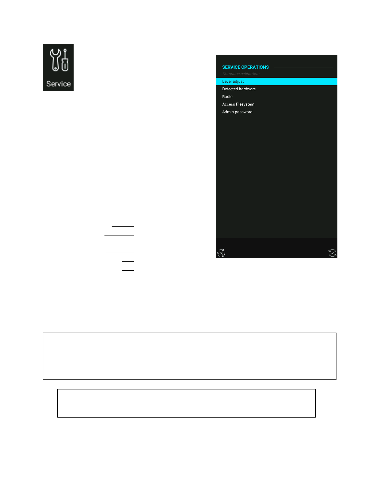
2.3.6 Service
Factory reset WARNING!
All files (TP, AS, APT) will be deleted and also pilots will be set to UNKNOWN – all pilot settings will go
back to factory settings (save current settings before doing factory reset to USB stick at Setup>Pilot>
Save user.)
Note
If LX Joy is not working after an update, use password 569 to force update.
Useful tools can be accessed under this
section, such as:
Compass calibration.
Level adjustment of units with AHRS.
Detected hardware.
With the use of admin passwords, the LX Zeus can be set
back to factory settings with the password 46486. This
will also delete all flights from Colibri II and Eos if they
are connected to the system.
Useful passwords:
Factory reset 46486
Grab image 315
Delete all flights 99999
AHRS disable 2478
Voltage offset 8658
Screen rotate 9109
Saving crash report 27274
Audio player on Eos 28346
LX Zeus v4.0.2
2.3.6.1 Screen rotation
The screen can be rotated after inserting the correct password. When a password is entered a reboot of
the unit is needed.
Use Password: 9109
51 | P a g e
Page 53

LX Zeus v4.0.2
2.3.6.2 Crash report
Saving a Zeus system crash report to a USB stick can be done by using admin password "27274".
If a system crash occurs, please send LX Navigation the file.
Once safely on the ground, put a USB stick into the Zeus and use the password in Settings->Service>Admin password to save crash report to USB key. This will help us to solve the problem and unwanted
restarts.
2.3.6.3 Compass calibration
The compass module has to be connected to the main unit via the 485 bus (in the case of a double seater,
connect to first seat). The module has to be installed horizontally without any pitch and, once done, enter
the compass calibration menu. Position the glider to north and press SET, after that the glider will need to
be positioned in all main magnetic directions as seen on the screen. When the glider is aligned correctly
press SET. When a window with the sentence ‘Calibration completed’ is displayed, press ‘SAVE’ using the
screen button and the system will exit back to the setup menu.
2.3.6.4 AHRS Level adjust (Pitch and Roll)
If the AHRS is not correctly aligned with the glider, then it
has to be adjusted.
Changes in pitch in flight are influenced by changes of
aircraft mass and changes of airspeed. This reference
pitch corresponds to a single airspeed (indicated airspeed
actually) and one aircraft mass. When the glider flies
faster or slower, or if the glider is heavier or lighter, then
the pitch angle deviates from the reference.
Adjustment procedure is:
The internal reference level of LX Zeus instrument
is most likely not to be ideal; therefore,
adjustment will be needed. On the ground, put
the glider fuselage in the position which best
matches the angle of incidence for the reference
airspeed. (Do not worry, if this is slightly wrong.)
Adjust the Zeus to this level.
Make a test flight with the glider. The aircraft
mass should be as close to the reference mass as
possible. Fly at the reference airspeed and
observe the pitch indicated by Zeus. Record this
pitch on paper. This observed pitch is the error,
which needs to be corrected.
52 | P a g e
Page 54

LX Zeus v4.0.2
Repeat the LX Zeus level adjustment, but now put the glider in such a position (lift or lower nose
or tail wheel) that the pitch on the LX Zeus indicates the same angle as observed during the
previous flight. Be careful to keep the wings level. This is now the reference position.
Do not move the aircraft and adjust the Zeus to be perfectly levelled, as follows, under Instrument
Procedure
Instrument procedure:
Go to SETUP / SERVICE / Level adjust
When the glider is ready to have its AHRS calibrated press the on-screen button adjust
(VARIO/FLARM)
Wait until status bar reaches 100 %
A message stating SUCCESS will appear
If satisfied with the new settings press the save
(TSK/MOVE) screen button
A message stating Parameters Saved will appear
Disable AHRS
To disable AHRS simply do as follows:
Push on zoom rotary switch
Go to setup
Go to Admin password
Enter password 2478 and confirm with a push on
the Zoom rotary knob
A disable AIRU window will open, there can be set:
o Choose a time period (in days) for how
long you wish to disable AHRS
o Disable AIRU (AHRS) until next activation
2.3.6.5 Detected hardware
In this section is shown what hardware is connected
(recognized) by the LX Zeus system.
53 | P a g e
Page 55

2.3.6.6 Radio (KRT2, ATR833)
Radio wiring diagram:
Please check LX Eos manual for wiring
diagram. For easy installation, it is
possible to get a special LX Eos-Radio
cable from LX Navigation.
KRT2 or ATR833 radios can be controlled from LX Zeus. It
is possible to adjust some functions (this is the dialog
available from the shortcuts menu):
o Volume
o Squelch
o Dual: If it is ON the radio listens to 2 frequencies
at once. The Active one has the priority. This
means that the radio will receive and transmit
from the active frequency and only receive from
the passive frequency (active one is priority
receiver)
o Switch between Active and Passive frequency
o Set Active or Passive frequency values
o Set Active or Passive frequency name (only
available when KRT2 is connected)
LX Zeus v4.0.2
(Note: other radio types will be added in due
course)
2.3.7 Localisation Settings
The following settings can be adjusted:
UTC offset to get local time
Date format
Time format
Position format
Language
A restart is needed once any changes have been made.
54 | P a g e
Page 56

2.3.8 Brightness
Note!
Not valid for LX Zeus 4.3 and LX Zeus 2.8. They do not
have the brightness adjustment option.
The display used in LX Zeus is a highquality sunshine readable display and its
backlight will satisfy the pilot’s
requirements in all flying conditions. In
the special case of increased backlight
being needed, the pilot is able to increase the intensity for
a limited time (30 minutes). After 30 minutes the backlight
will go back to the default brightness. Brightness can be
set by pressing the brightness icon in System settings.
LX Zeus v4.0.2
55 | P a g e
Page 57

LX Zeus v4.0.2
Variometer
bar
Status indicators
APT /TP or TSK name
Distance
Heading
IAS bar
Course line
Bottom row –
NavBox
Container
Final glide
indicator
3 Navigation modes
LX Zeus offers three modes for navigation. These modes are:
APT: navigation to airports stored in APT memory
TP: navigation to turnpoints (TP)
TSK: task navigation after task has been entered.
Switch between modes by pressing the A-P-T push button.
3.1 Navigation in APT / TP or TSK mode
There are three navigation pages possible (APT, TP or TASK) and also 2 subpages are possible and all are
selectable using the SUBP button.
3.1.1 Sort by filter
In every selection, the following filters can be used to find the desired airport or turn-point:
Name (alphabetical sorted from number-A-Z)
Distance (closest TP will be shown as the first)
Track (TPs -30 to +30 degrees from current track will be shown sorted by distance)
Arrival Altitude
3.1.2 Main graphic navigation page
56 | P a g e
Page 58

LX Zeus v4.0.2
The bottom row consists of NavBoxes. Bottom rows are selectable by pushing button 1-4. All NavBox
positions are customisable by following the simple procedure set out below.
Editing NavBox:
Give a long press on the Zoom rotary knob (blue frame will appear)
Select the desired NavBox position by moving the blue frame using the Zoom rotary Select position
to be edited followed by a short press of the Zoom rotary knob
Select the desired NavBox from the list. Confirm selection by pressing the Zoom rotary knob or
cancel the procedure by pressing the Volume rotary knob
If the row is full, press the 1-4 push button and add to a new empty NavBox container that will
appear. Use the same procedure for adding/editing described above
To finish the editing process, press Volume rotary knob
3.1.3 Second navigation page (1st subpage)
The second navigation page is divided into two sections.
The upper section consists of a vertical profile showing
the terrain, glide path distance, airspace, selected TP/APT
and cone.
The cone depends on the MacCready (MC) settings. The
lower line is a MC setting of 0.0 and upper the line
represents the selected MC value. If the glider icon is
between the upper and lower lines it means that it is still
below glide path for the selected MC, but that it could still
reach its destination if a lower MC setting was set. If the
glider is below the lower line it is too low and it will not
reach the intended destination.
The lower section shows additional APT / TP data such as:
Grass or asphalt runway with directions
Elevation
QNH alt
Flight level
QFE alt
Frequency of the APT
Your current radial
Your current distance from selected APT / TP
The lower section in TSK mode shows a circling log page,
wind profile page and a statistics page. Use the 1-4
button to switch between information pages on this
subpage.
57 | P a g e
Page 59

Statistics contain:
Note!
This 2nd subpage can be disabled under Setup>User
Interface.
Legs
Speed
Distance flown
Duration
Vario average
Circling on task in percentage
3.1.4 Third navigation page (2nd subpage)
The third navigation page shows terrain data that is split
between a map and an AHRS (artificial horizon and
reference system). If the LX AHRS is not connected to the
LX Zeus system, only the terrain profile is shown.
The pilot can select full or half screen for 3D view with
AHRS.
LX Zeus v4.0.2
3.2 APT mode (navigation to airports)
LX Zeus’ airport database is stored in a special .af file format (LX Navigation airport format). Only one .af
can be active at the same time. To transfer and/or select new .af file go to Setup>Transfer>Airports.
APT mode consists of three navigation pages:
main page is map navigation page,
1st page is a subpage with information about selected airport and glide path,
2nd page is a subpage with a map and a 3D view (with AHRS) or vertical profile.
Switch between pages by pressing the SUBP button.
Note: The second subpage (3D terrain) can be disabled (see Setup>User interface).
Airports are marked with a symbol (filled black line means airport with asphalt, a line without fill is a grass
runway):
58 | P a g e
Page 60

LX Zeus v4.0.2
Note!
When using the Name filter, input first letters of the
airport name. Use the Zoom rotary knob to scroll and
press it for confirmation. You don’t need to input all
characters, just first two or three and after that you can
go on by pressing the Zoom rotary knob. Input of more
characters reduces the number of possible airports.
The RWY orientation shown matches the real situation. Extended Airport data is available in the lower
section of the second subpage. Pressing the 1-4 button on the second subpage will bring up some
additional screens (wind profile, thermal history, etc.).
3.3 How to select an airport?
Airport selection is available from any mode of operation
and also from any subpage. Press the SELECT button
(short press) and the selected menu will open. Use screen
button APT with a short press of TSK/MOVE to start the
selection dialogue. If already on the TSK navigation page,
give a short press on the Volume rotary knob which is a
shortcut to the APT selection menu.
Reachable APTs from the current position are shown in
green, non-reachable are labelled red.
Scroll with the Zoom rotary knob to select a filter such as:
Country, Name, Distance, and Track or Arrival altitude to
reduce the number of offered Airports. If using a sort by
distance filter, then it is not possible to use a named filter.
Using a country filter will show airports only from the
selected country. After the airport of interest is found
confirm the choice with a short press on the Zoom rotary
knob. The APT screen will open giving navigation to the
chosen destination.
59 | P a g e
Page 61

3.3.1 APT selection from NEAR function
Note!
Selection is limited to 200
nearest points
LX Zeus also offers NEAR function. After a long press on
the SELECT/NEAR button, the nearest Landable points
and User markers will be offered. The list includes
airports from the airport database, turn-points that are
declared as landable and Markers.
LX Zeus v4.0.2
3.4 TP mode (navigation to turnpoints)
TP and APT modes are similar in structure. The only important difference is that the navigation is
towards turn-points that are stored in the turn-point files. Turn-point files (.cup or .cupx) should be
uploaded via a USB stick. (See Setup>Transfer for details.) An almost unlimited number of .cup/.cupx
files can be uploaded. Because turn-points can have different attributes the symbols that represent the
various types are different.
TP mode consists of three navigation pages (main page is map navigation page, 1st subpage with
information about selected airport and glide path, 2nd subpage with a map and a 3D view (with AHRS) or
vertical profile. Switch between pages by pressing the SUBP button.
If using .cupx files turn-point images are shown on 1st subpage. A .cupx file can be prepared on a PC or on
LX Zeus. To add pictures to turn-points use Select TP menu. On the bottom of the menu is shown the
Upload photo screen button. Use it to transfer pictures from an USB stick to the selected turn-point.
Note: The second subpage (3D terrain) can be disabled (see Setup>User interface).
60 | P a g e
Page 62

LX Zeus v4.0.2
Note!
Up to three turn-point files can be active at the same
time. The activation should be performed under
Setup>Transfer. Turn-points included in all three files will
be available for navigation. The first file (TP/TSK/Eos) will
import tasks. Imported tasks are available in TSK
navigation mode.
Extended TP data is available in the lower section of the first subpage. The upper part of the display (1st
subpage) is vertical terrain profile.
To activate the screen buttons for the TP options the Zoom
rotary knob should be pressed when on TP screen (not at
APT or TSK).
3.4.1.1 Edit TP
Press Zoom rotary knob on main TP navigation screen,
select screen button Edit TP and a new window called Edit
turn point will open.
61 | P a g e
Page 63

3.4.1.2 Create User turnpoints
Note!
Type option offers plenty of turn-point designators. The designator defines the symbol that will appear
on the display. A landable point will be shown on the list in NEAR function.
User turn-points are turn-points that are created by the
pilot on LX Zeus
Auto TP
If Auto TP is selected, a user TP will be created, with the
current position and the current time as its name. To edit
an Auto created TP use the Edit TP function.
By hand
Press the Zoom rotary knob on the main TP navigation
page and a menu with screen buttons will open. Press Add
TP.
The following information can be entered:
Name.
Details (not obligatory).
Type (grass, field, tower…).
Longitude, Latitude.
Elevation.
LX Zeus v4.0.2
Other input fields may not be highlighted due to the turn-point type being added. Finish the process with
Add turn-point.
62 | P a g e
Page 64

3.4.1.3 Add Marker
Important!
Turn-points without country designators are
selectable only when using Country “All” option. This
is also valid for user turn-points. Check and correct all
files manually before uploading them to LX Zeus.
The philosophy of having a marker is to mark a position,
to which the pilot might need navigation assistance
(landable field, etc.).
For example, if flying towards a non-landable area, and
the last landable field is seen below, then, over this
landable field, a marker can be created. It would then be
easy to navigate back to that marker, which can be
selected at NEAR/TP, or at select TP.
There can only be one marker at a time. If another marker
is created, the first one will be replaced by it. The marker
can be changed to a regular more permanent TP via EDIT
TP. Such a turn-point can be deleted via DELETE TP.
LX Zeus v4.0.2
3.4.1.4 Delete TP
Only user created turn-points and markers can be
deleted. To delete a TP the Zoom rotary knob should be
pressed, then select screen button DELETE TP and a new
window will open. Select the TP by rotating the Zoom
rotary knob and confirm it with a short press.
3.4.1.5 Send TP
If Send TP is selected, then the current selected TP will
be sent to the second seat (all info about the TP will be
sent).
3.4.2 Selecting Turn-points
The selection process is similar to APT. Use SELECT button
to start the process and press on-screen button TP.
Country, Name and sort by distance, track, arrival altitude
filters will expedite selection. Turn-points are displayed by
symbols. If on a TP navigation main page the shortcut
(press Volume rotary knob) can be used.
63 | P a g e
Page 65

3.4.2.1 Selection from Near
LX Zeus Near function offers Turn-point selection based
on distance. It is also uses a Country filter, use All if you
want to select from all turn-points.
3.4.3 Uploading TP photo
It is possible to upload a photo and assign it to a TP.
The procedure to upload a photo:
Insert USB stick
Press SELECT button
Select TP
Choose with the Zoom rotary knob to display the
TP you wish to assign new photo to
Select - Upload photo
Choose the photo on USB stick
Confirm with a push on the Zoom rotary knob
LX Zeus v4.0.2
64 | P a g e
Page 66

LX Zeus v4.0.2
Note!
Tasks that you want to upload to LX Zeus
should be a part of a .cup file and should
be selected under SETUP>TRANSFER as
TP/TSK/Eos file. It is very important
that you name tasks, otherwise the
Zeus won’t recognize them.
3.5 TSK mode (navigation on task)
Every task consists of at least a start point and the finish point. There may be multiple turn-points
between the start and finish point. Take-off and landing points can be added (this doesn’t have any
influence on task statistics).
3.5.1 Task organization
Zeus has a storing capacity for 100 tasks. 51 tasks can be
imported from one .cup file and such tasks are called
imported (IMP), the user of LX Zeus can create another 49
tasks. They are called User (USR) tasks. After creating or
selecting TSK, the TSK will be automatically declared (and
sent to all connected flight recorders).
To delete all existing USR tasks go to Select TSK dialog and
then select Clear all. Zeus then asks confirmation and
deletes all USR tasks.
3.5.1.1 Task declaration
Declaring the task is an automatic process. After a task is
constructed, and exit is pressed (Volume rotary knob), a
message on the LX Zeus screen appears: TASK DECLARED!
This means that LX ZEUS will start sending the declaration
data to connected flight recorders. The declaration is sent
to Eos, Colibri II, Colibri X, Era etc. automatically – with all
TPs, edited zones, limitations etc...
Eos and Colibri II have the priority and will receive the data
first. After this, the declaration data will be sent to FLARM.
This process will take about 30 seconds. After the process is
finished all LED lights will switch off on the FLARM display
and the red POWER light will start blinking. This means that
the process of sending task declaration to FLARM is
finished.
3.5.2 Task selection
To select a task from the LX Zeus internal task database, the
pilot should use the SELECT button and then select the
screen button TSK. Use the Zoom rotary knob to select the
task of interest. Confirm selected task by pressing the Zoom rotary knob and another window with task
details will be shown. Choose the option for the Finish altitude of the task to be less than 1000m below
the altitude at which start line was crossed. (as appropriate). The Final Glide will be calculated in
correspondence with this altitude, but only if the option is selected.
Exit by pressing the Volume rotary knob twice, or wait until the window closes automatically (if auto close
inactivity timeout is enabled).
65 | P a g e
Page 67

3.5.3 Task creation by hand
To create a new task press TSK/MOVE (short press) or
give a short press on the Zoom rotary knob if you are on
TSK main navigation page. The task can be created by
hand by using NEW or EDIT screen buttons. Edit will make
it possible to edit an existing task and New will offer the
creation of a new task. Both tasks will be saved under the
USER part of the task internal database (if editing an IMP
task, it will automatically change from IMP to USR).
The procedure:
Press TSK/MOVE button
Select screen button NEW (TSK/MOVE) or EDIT
Task (VARIO/FLARM)
If an AAT task, then add time by pressing the
Zoom rotary knob and rotate Zoom/Volume
rotary knob, terminate by pressing Zoom rotary
knob
Rotate Zoom rotary knob to add Task name –
press Zoom rotary knob and add name
Rotate Zoom rotary knob to TPs – press Zoom
rotary knob and Select/Insert TP or APT
To finish the task creation procedure, press the
Volume rotary knob – a message informing that
the task is declared will be shown
LX Zeus v4.0.2
66 | P a g e
Page 68

3.5.3.1 Creating a task in Pan mode
Note!
You can see the entire task on the
map at once by using TASK ZOOM.
Access TASK ZOOM by rotating Zoom
rotary knob. The task zoom is active
only on the ground!
Note!
An active zone has a different colour
to an inactive zone (colours can be
adjusted under Setup / User Interface
/ Task Colours.)
It is possible to create a task in Pan mode by following
these steps:
Press SELECT button on TSK screen
Select Pan mode on screen button
Navigate to the point on the map using the
Zoom/Volume rotary knobs
Select New task
Select Add TP (the first TP you select will be your
Start and Finish point)
Add as many TPs as required
When adding TP’s has been completed select
Finish task
The task can be edited in edit mode - Start,
finish, TP’s, zones
When the task is created, it is declared and sent to
Colibri II / Colibri X / Eos / Era / Flarm etc automatically.
LX Zeus v4.0.2
67 | P a g e
Page 69

LX Zeus v4.0.2
Note!
AAT task – if the sector is bigger than 10 km, then
AUTO next won’t be active. If the sector is
smaller than 10 km, then you have to uncheck
MOVE in the ZONE menu
Note!
Default task zones can be adjusted under Setup /
User Interface. You are able to adjust default start,
waypoint and finish zone to make task creation
easier.
3.5.3.2 Create and Edit Zones
The ZONE function makes it possible to create any known geometry for turnpoints, start and finish point.
The zone can be edited by selecting TSK EDIT/ select TP / ZONE.
After a press on the Next zone or Previous zone buttons, the pilot can change zone settings quickly without
any additional actions.
For START and FINISH zones the pilot can select if this zone is a straight line or not.
Auto next option enables the Zeus automatically to switch to the next turnpoint once the sector has been
reached. This function is active by default if the sector’s radius is below 10 km (racing task). Larger sectors
do not have this option as a default. If Auto next NO is active, MOVE function (for AAT) will become active
and that makes it possible to modify the task distance even before flight.
MOVE during an active TSK is also possible. A long press on the push button TSK/MOVE will open a Move
window. The ‘custom turnpoint’ can then be moved by rotating the Zoom and Volume rotary knobs. The
important information is displayed next to the moved turnpoint (Total distance, Required speed, final glide
at MC 0.0 and selected MC).
68 | P a g e
Page 70

3.5.4 Task Functions
Automatic and manual starts are possible by using
functions ARM and NEXT TP. All functions are available by
pressing the Zoom rotary knob when on the TSK
navigation page or by pressing the TSK/MOVE button on
other pages.
3.5.4.1 Task Start
To start a task automatically use the ARM command
which is displayed after a press of the TSK button. Arm
means that the task will be started automatically after
crossing the start line.
The start line can be crossed multiple times, the time of
the last valid start will be used for calculation of statistics.
Every valid start is indicated by a green message on the
screen.
Under Settings>User Interface>Track/destination settings
can be selected whether navigation is aimed at the zone’s
center or the zone`s closest point.
LX Zeus v4.0.2
During flight the task can be disarmed. Activation of ARM
and DISARM are clearly shown on the display in a message
and by an ARMED icon.
If pressing ARM before crossing the start line is forgetten,
and the glider is already on the task, then the second option
is to press Next TP. Next TP command will change over to
next TP every time when activated, regardless of whether
the glider is in the sector or not. It will also take the latest
start line crossing time, to ensure that task statistics will be
correct.
3.5.4.2 Task Restart
After a task has been started a restart can be done at any
time. Use the Restart button in the TSK menu. The Restart
button will become active once the task has started. After
restarting all task statistics data will be deleted and ARM
status will become active again making it possible to do
another automatic start.
69 | P a g e
Page 71

LX Zeus v4.0.2
Note!
Manual changeover is only possible by using the Next TP command. Next TP is always active and it will
execute changeover to next TP at any time. Activating this command, when still out of the sector, will
degrade statistics data. Solutions: delete TPs that re not required, or extend the zone/sector of TPs.
3.5.4.3 Next Turnpoint
Changeover to next turnpoint can be done automatically
or manually. Automatic changeover will occur when Auto
next of the individual zone is enabled. If the zone is not
Auto next, then the message INSIDE zone will appear. If
going to the next turn-point, press TSK button and then
press NEXT TP screen button.
Default setting for Auto next:
If R1 is set below 10 km then Auto next is
activated (automatic changeover is enabled).
If R1 is set above 10 km then manual changeover
is necessary.
When flying a task, and when a new TP becomes active, the same TP is set as the navigating turn-point
on the TP page.
3.5.4.4 Saving TSK to USB
LX Zeus offers the option to save created or edited tasks to a USB. A USB stick has to be inserted into the
USB port. After the creation of a Task, press the Volume rotary knob to get out of edit menu and declare
the task. After that, press TSK button and press Save to USB using the screen button. The Task will be saved
to the USB stick as a .cup file with current task and all TPs and zones on this task.
3.5.4.5 Clear TSK
When in task editing menu, the whole task can be erased. First press Clear task screen button, then press
YES to confirm the choice or NO to terminate the process without erasing the task.
70 | P a g e
Page 72

LX Zeus v4.0.2
3.5.4.6 Team Code
Team code is a feature that gives the cabability of visualizing
the position of a wingman and yet keep it secure. A short
press on the TSK button will bring up the Team code screen
and a menu requiring the team code and reference point will
appear.
To use this feature there are three NavBoxes available on LX Zeus (TEAM CODE, TEAM BEARING and TEAM
DISTANCE).
Before sending a position with the team code all partners should use same reference turn-point. For better
indication (more accurate) a reference point which is 50-150 km away from every position in the flight
should be chosen (for example the task that is flown should be in the 50-150 km radius of the reference
point; if the task is bigger a second reference point should be chosen and entered once an agreed distance
has been flown). In flight, when partners are interested about their location, team codes should be
exchanged via radio. The pilot`s current code is visible in the Team code NavBox. Partners are able to see
bearing and distance of each other in the TEAM BEARING and TEAM DISTANCE NavBoxes.
The feature works on the principal of the polar coordinate system. The baseline condition is having the
same reference point. When this is chosen, LX Zeus calculates distance and bearing from this reference
point to the pilot’s location and codes it into Team code. The first two characters mean the angle and the
last two the radius from the reference point. When this information is given to a partner with the same
reference point chosen, LX Zeus can calculate direct bearing and distance to the other partner. The process
works in both directions between partners.
3.5.4.7 Limits
Here are the task start conditions that can be selected. It is
possible to:
Define gate time
Define before start:
o Below altitude
o Below time
Define start conditions:
o Start altitude
o Start ground speed
For the explanation of these terms read more under chapter Start Conditions/Limitations
3.5.5 MOVE Function (during flight)
When flying an AAT, big sectors are set and therefore the pilot has to decide where to turn to the next
turn-point. The MOVE function helps the pilot to find an optimum solution. After a long press on the
TSK/MOVE button the MOVE function will become active. Use Zoom and Volume rotary knobs to move
the turn-point. All task relevant data that is affected by the move is displayed next to the zone.
During straight flight, when far from the zone, the track will appear in the zone in the MOVE function.
When the glider is in the zone, the real-time picture (glider with its track), will also be shown on the MOVE
dialog.
71 | P a g e
Page 73

LX Zeus v4.0.2
3.5.6 Task Zoom
By rotating the Zoom rotary knob to the left the Task zoom will be activated which will show the whole
task on the screen. Task zoom will show all turn-points (moved and modified) with airspace. Task zoom is
not visible while flying, only on the ground.
72 | P a g e
Page 74
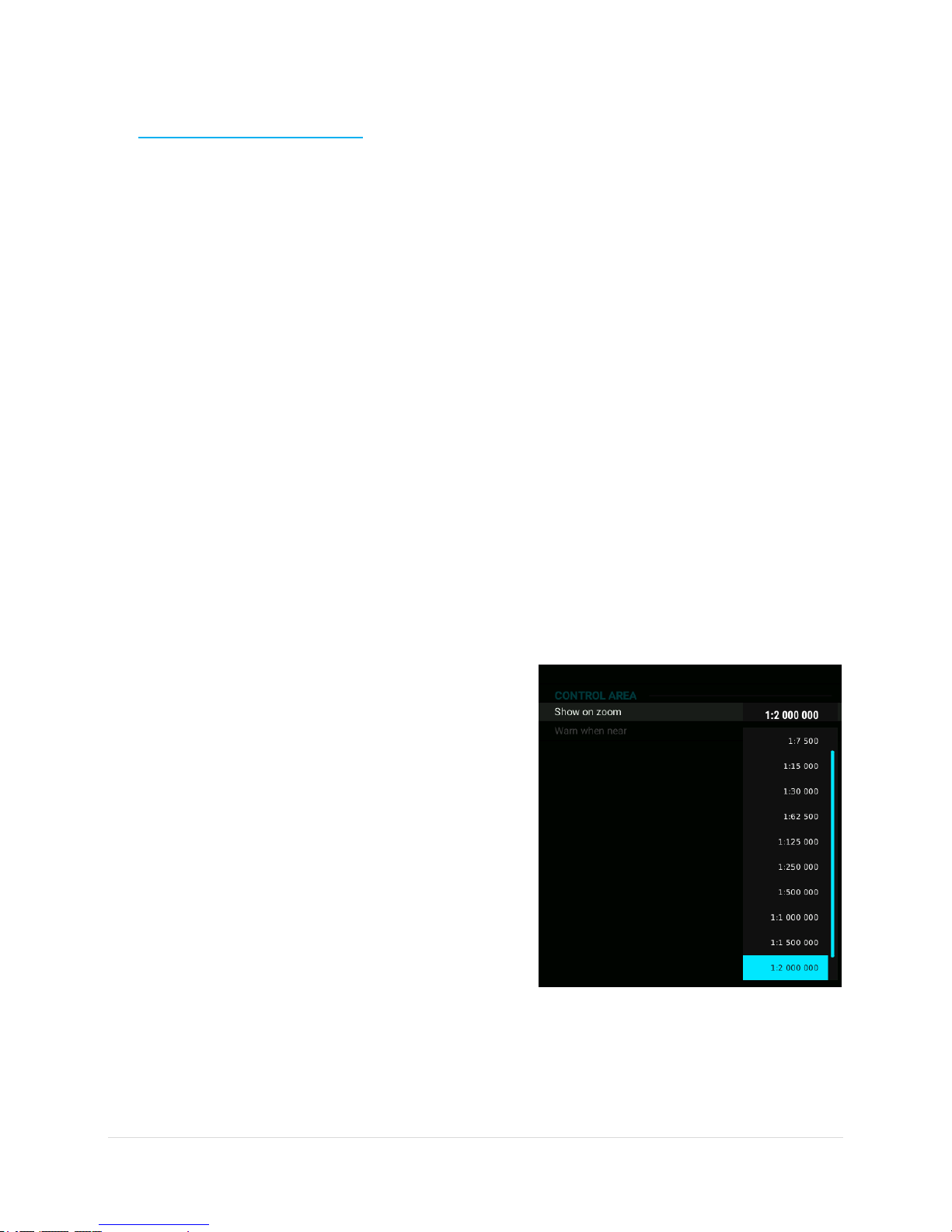
4 Airspace Management
Airspace on LX Zeus can be managed by the pilot to achieve
the optimum relationship between loading the display and
its readability. Too much information will reduce the
readability of the display.
1.1 Basic airspace settings
Settings are available under Setup > Airspaces. The user can
select warnings and appearances related to the zoom level.
4.1.1 Hide airspace above
The airspace sections that are much higher than the
altitude of the glider are not relevant. Disabling them will
significantly reduce the density of information on the
display. Use Hide airspaces above airplane to define the
altitude margin that considered to be required for a safe
flight.
LX Zeus v4.0.2
4.1.2 Other settings
Hide above QNH altitude allows a selection of the QNH
altitude above which the airspace should be hidden.
Horizontal and vertical distance warnings can be set also
in this section. LX Zeus will warn a user at a predefined
warning distance. Default settings are 100m vertically and
2 km horizontally.
Warning timeout at takeoff allows a choice as to how
long after the take-off there won’t be any airspace
warnings.
4.1.3 Define appearance of airspace
related to zoom level
Zoom levels can be selected at which different airspace
types will be visible. Use the Show on zoom function to
define to which zoom level the airspace type is to be
visible on the display. Two extreme situations are
described with always and never. Factory default settings
for all airspace types are always.
73 | P a g e
Page 75

4.1.3.1
If set to disabled ( ) the airspace info box for this
airspace type will not appear on the screen. Setting
checked ( ) will produce airspace info box information.
The airspace info box is an indicator on the main screen.
The pilot is able to move/resize the box and also to
customize colours. This can be done under Setup >
Layout.
The airspace info box contains airspace name, horizontal
and vertical distance and is by default positioned in the
upper section of the display. The nearest point to entering
the airspace becomes visible on the display. As long as the
warning isn’t critical the text colour is blue.
Airspace is displayed at 1st subpage in different colours
(yellow and red). Airspace is also seen in a 2nd subpage,
where the page is split between a map and a vertical
profile (but only if AHRS is not connected to the system).
LX Zeus v4.0.2
Explanation of airspace info box
The picture shows that the glider is in the CTR MARI
airspace. It shows that the glider is horizontally 11.2 km
inside and vertically 82 m outside. The red warning
confirms that the glider is inside, the yellow that it is close
and the green warning means it is outside.
74 | P a g e
Page 76

4.1.4 Disabling airspace sections
Edit airspace dialog after a press on
EDIT button
During flight, airspace warnings may appear on the screen
(picture on the right). Pressing on one of the screen
buttons can easily disable the warning. Airspace warnings
can be disabled for specific amounts of time (5 minutes,
10 minutes, 30 minutes, 1 hour, 3 hours or for whole day).
Airspace can also be disabled whilst on the ground. Press
SELECT button to open airspace dialog. Airspace is sorted
by distance. In the upper part of dialog there is a list of
airspace with name of the airspace, horizontal distance
and operating altitude from and to in meters/feet and
also as a Flight level. The bottom part of dialog shows
airspace around the glider. The colour of the currently
selected airspace is blue.
LX Zeus v4.0.2
Different airspace can be selected with the Zoom rotary
knob. By rotating the Volume rotary knob the zoom level
can be changed. After a press of the Zoom rotary knob or
a press on the EDIT screen button, a dialog with additional
options for selected airspace will appear, as follows:
Airspace type
Airspace class
Disable airspace until specified date
A screen button DISABLED ONLY will show only disabled
airspaces.
75 | P a g e
Page 77

5 GPS signal management
Note!
LX Zeus can adapt baud rate to any
value between 4800 and 38400
automatically, so baud rate of GPS
source connected to Flarm input
does not matter as long as it is in the
range (4800-38400).
Note!
Colibri II is powered from LX Zeus. All
settings and declarations are sent
from LX Zeus to Colibri
II/Eos/Era/MOP/Flarm. There is no
need for any additional setup on
Colibri II/ Eos/Era/MOP/Flarm.
LX Zeus has three GPS signal inputs, they are on the back
of the unit. The following devices can be connected:
Colibri II
Flarm or any device with NMEA output
LX Eos/Era via CAN bus
5.1 Colibri II socket
The Colibri II socket can be used only to connect a Colibri
II unit. It delivers power (5V) for the Colibri II and
sends/receives data directly without any data interface.
The communication is bidirectional. Every unit equipped
with Colibri II is supplied with a suitable connection cable
(USB mini to 6-pin RJ11).
5.2 Flarm plug
A Flarm marked input is a plug and play solution for
connecting any unit that has 6-pin RJ11 IGC compatible
connector. This port also delivers 12V.
LX Zeus v4.0.2
The following units can be connected without any
additional adaptor:
Colibri, LX 20 – 2000, VL, LX Flarm RB, LX Flarm
MB, Flarm (Swiss)
5.3 LX Eos – CAN plug
LX Eos/Era connects to a CAN port, it doesn’t matter which one is used. If an Eos is connected to the
system, please check that there is no CAN terminator used on the CAN bus (CAN terminator is already
built-in to the inside of a LX Eos/Era device).
5.4 GPS signal for navigation
All GPS inputs are used on LX Zeus. This means that LX Zeus is supplied with valid GPS signal as long as at
least one connected GPS receiver delivers valid data. A symbol positioned in the right upper corner of the
display shows GPS signal status:
red GPS BAD
green GPS OK
white symbol with means no GPS data is present
76 | P a g e
Page 78

LX Zeus v4.0.2
6 LX Zeus and LX Eos/Era
LX Eos/Era and LX Zeus together create a very compact and robust system. They are connected with a
single CAN cable (use CAN port on both devices).
All the data and power supply is transmitted through this cable. LX Zeus and LX Eos transfer all the
necessary data from one to another. When LX Eos/Era is connected to LX Zeus all settings for LX Eos/Era
are made on LX Zeus and transferred to LX Eos/Era.
When LX Eos/Era and LX Zeus are connected, the setup screen cannot be seen on LX Eos/Era, because the
setup is done on LX Zeus. If the main power supply fails (ie.: Zeus does not work anymore), and it is still in
flight mode, LX Eos/Era will keep working as it has an integrated battery with about a three hour duration.
In such cases the Setup page will appear on LX Eos/Era and there is an option to set all important
parameters on LX Eos/Era device. To see LX Eos/Era setup structure, please check LX Eos/Era manual.
LX Eos/Era has an integrated ENL sensor.
6.1 LX Eos/Era power management
Connect the main power cable with a switch to LX Eos/Era. Immediately after LX Eos receives power, the
LX Zeus will automatically switch ON, without any pilot interaction. When the main power from LX Eos/Era
is cut, LX Eos/Era will start a 3 second countdown before it turns OFF. LX Zeus and other CAN devices are
turned off immediately. When for some reason the main power supply is lost during flight, LX Eos/Era will
continue to record the flight for about 3 more hours.
The internal battery inside LX Eos/Era is automatically charged when there is a 12V power supply and this
means that it is always available to provide internal backup power supply for LX Eos/Era. The charging
process of an empty battery takes around 2 hours.
77 | P a g e
Page 79

6.2 LX Eos/Era – Zeus interaction
Important!
Any change on task will immediately update LX Eos’ internal task. As long as on ground (not flying),
the new data will be written into declaration of LX Eos flight recorder. The same will happen with pilot
data. After take-off, the task synchronization will start working but the declaration in the flight
recorder will remain unchanged (IGC rule).
After connection between LX Eos/Era and LX Zeus is
established, both units will start to communicate over the
CAN bus. The connection is established automatically
without any pilot interaction.
6.2.1 Commands and declaration transfer to LX Eos/Era
Every time the system is turned on the following data is
sent to LX Eos/Era:
Pilot data: After initial setup on LX Zeus (also
pilot 2nd name in the event of a double seater
configuration)
Recording interval
Other data related to flight recording with
recording (Event repetition…)
Selected task: the task will become declared
Active turn-point file (.cup in TP/TSK/Eos slot)
Active turn-point navigation
Other vario settings
LX Zeus v4.0.2
A long press on the EVENT button, will send the event
command to LX Eos/Era. The event command can be
sent also from a second seat.
For more information about LX Eos/Era system, refer to LX Eos/Era manual.
78 | P a g e
Page 80

LX Zeus v4.0.2
Password 99999:
Password 99999 will delete all flights from Colibri II and LX Eos
Important!
Any change of task, will immediately update the Colibri II internal task. As long as it is on the ground
(not flying), the new data will be written as a new declaration to the Colibri II flight recorder. The same
will happen with pilot data. After takeoff the task synchronization starts working but the declaration
in the flight recorder will remain unchanged (IGC rule).
7 LX Zeus and Colibri II
LX Eos and LX Zeus together create a very compact and robust system. All flight recording related settings
are sent from LX Zeus and, in their relationship, LX Zeus is the master and Colibri II is a slave. This is why it
is possible to install Colibri II in an inaccessable place (under/inside instrument panel), as long as the Colibri
II position ensures good GPS reception. It is essential that the Colibri II has version 1.93 or higher installed.
Colibri II has an integrated ENL sensor.
7.1 Colibri II power management
Once the LX Zeus receives power, the Colibri II will automatically switch ON without any pilot action. After
landing the Colibri II will remain ON as long as LX Zeus is powered. When LX Zeus is switched OFF, Colibri
II will work for a limited time and switch OFF after approximately 5 minutes. Colibri II is permanently
charged from LX Zeus and this ensures that the Colibri II battery will be always full. When, for some reason,
battery power is lost on LX Zeus during flight, Colibri II will continue to record the flight for up to 15 hours.
7.2 Colibri II – LX Zeus interaction
Once a connection between Colibri II and LX Zeus is established both units start to communicate using a
special LX protocol. The connection is established automatically without any pilot action.
7.2.1 Commands and declaration transfer to Colibri II/Eos/Era
Every time the system is turned on the following data is
sent to LX Eos:
Pilot data: After initial setup on LX Zeus (also
pilot 2nd name in a double seater configuration)
Recording interval
Other data related to flight recording with
recording (Event repetition…)
Selected task: the task will become declared
A long press on the EVENT button generates an event command that is sent to Colibri II. An event
command can be sent also from the second seat.
79 | P a g e
Page 81

LX Zeus v4.0.2
GPS signal priority
If there are more units (LX Eos, Colibri II and/or Flarm) connected to LX Zeus, LX Zeus will use best GPS
signal reception.
Note!
In the case of LX Flarm Red Box there must be only 1 SD card inserted at once; either in LX Zeus micro
SD card reader on the front of the unit or in LX Flarm Red Box unit, but not in both at once.
8 LX Zeus and Flarm
Flarm should be connected to the FLARM port on the back of the LX Zeus; Flarm will also receive power
via this port. If Flarm is connected to the aircraft power network via its own power input wires, a shortcircuit problem does not occur due to a built-in diode. This separates both power supplies. Up to two Flarm
external displays can be connected to ports marked as Flarm external display. The SD card slot on the LX
Zeus front unit is directly connected to Flarm SD interface (valid for RB), without LX Zeus interaction.
The SD card may be used for:
Flarm firmware update (Red Box or Mini Box)
Downloading of flights stored on Flarm (Red Box
or Mini Box)
On the rear of the LX Zeus 5.5 and 7.0 there is enough space to install LX Flarm Red Box as an integral part
of the system. All connections are plug and play. It is also possible to install any other Flarm compatible
devices.
Original Flarm (Swiss) can be used as well. LX Zeus will show objects from Flarm on the display and provide
power for Flarm. Task declaration with pilot information is automatically sent from LX Zeus to any Flarm
with a flight recorder once the task has been declared on LX Zeus.
The SD card slot cannot be used for Original Flarm (Swiss).
80 | P a g e
Page 82

LX Zeus v4.0.2
Declaration warning!
The SD card should be inserted into the SD slot without any CONFIG (.cfg) file on the card! If .cfg is on
the card, then this file will have priority and the declaration will be wrong. Thus, there would
be .cfg declaration instead of LX Zeus declaration inside IGC file so it will not work!
Important!
Flight recording settings (recording interval…) will not be sent to Flarm, use SD card or Flarm Tool (see:
www.lxnavigation.com – support / manuals: LX Flarm update instructions.
8.1 Flarm external displays
LX Zeus makes it possible to connect up to two Flarm external displays. Both connections are controlled
from Flarm directly without any LX Zeus influence. LX Zeus system also provides 3V power for Flarm
displays.
8.2 Task declaration into Flarm
In the case of an IGC approved version of Flarm, connected to Zeus Flarm port, an automatic declaration
process is executed. The process is identical whether with LX Eos or Colibri II. This means that the current
task and pilot data is sent to Flarm automatically.
The declaration process takes around 30 seconds. After the process is finished all LED lights on the Flarm
display will switch off and the red POWER light will start blinking. This means that the process of sending
task declaration to Flarm is complete.
8.3 Transferring files from Flarm
Transferring files from Flarm to a micro SD card is a very easy process. The micro SD card has to be inserted
into the micro SD port, on the front of the unit (in case of LX Flarm Red Box). After the flight is completed,
wait for around three minutes, then turn LX Zeus OFF and ON again. After switching on, a red POWER LED
light on the Flarm display starts blinking. All other LED lights should be off. This means that all the flights
that were not already on the micro SD card are now transferring to the SD card. After the red POWER LED
light stops blinking the process is finished. The micro SD card, which will now contain all the flights from
Flarm, can now be removed.
If the micro SD card has not been used for a while Flarm will automatically transfer all flights, that are not
already on the micro SD card, from its internal memory to the micro SD card. If there are a lot of flights to
transfer, the process may take up to 20 minutes! Flarm will always store a maximum 20 flights, so, if a 21st
flight is recorded, then the oldest flight will be removed automatically.
81 | P a g e
Page 83

LX Zeus v4.0.2
8.4 LX Flarm RedBox / LX Flarm MiniBox update
LX Flarm RedBox and LX Flarm MiniBox can be updated via SD card or PC by using Flarm Tool software.
Read update procedure at: www.lxnavigation.com – section SUPPORT / MANUALS: LX Flarm update
instructions.
8.5 Flarm PINOUT
9 LX Zeus and Garrecht
Garrecht units can be connected to LX Zeus using supplied cables. A declaration to Flarm will be sent
directly from LX Zeus.
Updating Garrecht units is not possible via LX Zeus. The connection schematic is shown below.
9.1 LX Zeus and Garrecht TRX-1090 ADSB / TRX-2000
9.2 LX ZEUS and Garrecht TRX-1500
A special cable is needed for this connection. This cable can be ordered from LX Navigation under the
following code: LX-TRX1500.
82 | P a g e
Page 84

LX Zeus v4.0.2
10 LX Remote Stick
LX Zeus can be controlled with a LX Remote Stick. The stick is a standard LX Navigation product, which does
not differ significantly from sticks used by LX 7000/7007. Therefore, the upgrade of an existing stick is very
easy. The Remote should be connected to one 485 plug and no special initialization is necessary. But note
that only the short press function is supported with LX Remote Stick.
10.1 Use of LX Remote Stick
The plus and minus buttons have the same function as the Zoom rotary knob on LX Zeus.
The enter () and escape (X) buttons have the same functions as pressing Zoom and Volume rotary knobs.
Zoom IN/OUT:
Use buttons Minus and Plus on the LX Remote Stick.
Select screens (APT, TP, TSK):
Use APT button and press it until you will have the indication on the top in left
corner of APT, TP, TSK.
Select second page:
Use SUB button on LX Remote Stick.
Change information at second page between info and vertical profile:
Use 1-4 button, you can also Zoom In/out with Minus / Plus
Change MC:
Press MC.
Press Minus / Plus button.
Press X to go back to navigation.
Select TP, APT:
Press X button.
Use MINUS to go to Country, Name or Sort by Distance filter.
Use Check/confirmation button to select the filter (Example Name filter: press Check, press Plus to change
the character and press confirmation, go down with Plus and select the TP or APT with Check button).
Select in TP/APT/TSK mode
Pressing the “check” button will activate different screen buttons. The selected screen button will be
highlighted in yellow. Moving to a different screen button is done by using + or – buttons on LX Remote
Stick. To select a highlighted button click the “check” button and the next dialog will open.
10.2 LX Remote Stick on second seat
LX Remote Stick for second seat is the same as for the first seat (no different firmware unlike with the LX
7000/7007). The unit should be connected to the second seat unit using the 485 bus.
83 | P a g e
Page 85

LX Zeus v4.0.2
NOTE!!
In order for LX Zeus to work with LX Joy, the software version on LX Zeus should be at
least 3.2.2 or higher.
Short press: VARIO
Short press: ESC
Short press: PTT
Short press: TSK
Long Press: MOVE
Short press: FN
11 LX Joy
11.1 General
LX Joy is an ergonomically designed, leather covered remote stick handle for gliders. As seen by the pilot,
it consists of 5 buttons and a navigation switch on the front side, one button on the rear side, a built-in
electronic circuit and wiring.
The internal diameter of the bore can be 19,1 mm, 20,1 mm or 24,3 mm. It is important to point out the
dimension when ordering your remote stick. (If the glider type is specified when ordering LXN will know
what size is required)
11.2 Button description
NORMAL MODE (LED OFF)
(as seen by the pilot)
84 | P a g e
Page 86

LX Joy middle button:
Press: ENTER
SELECT
1-4
SUBP
APT
Short press: PTT
Long Press: PTT
Short press: FN
Short press: STAT
Short press: FLARM
Short press: ESC
Long Press: /
LX Zeus v4.0.2
ZOOM/VOLUME MODE (LED GREEN)
85 | P a g e
Page 87

LX Joy middle button:
Press: ENTER
ZOOM OUT
VOLUME -
ZOOM IN
VOLUME +
Short press: ZOOM IN
Long Press: /
Short press: PTT
Long Press: PTT
Short press: FN
Long Press: /
Short press: ZOOM OUT
Short press: ESC
Long Press: /
LX Zeus v4.0.2
PAN MODE (LED RED)
86 | P a g e
Page 88

LX Joy middle button:
Press: GO TO
Move right
Move up
Move left
Move down
LX Zeus v4.0.2
87 | P a g e
Page 89

11 Second seat unit
Note!
Flarm, LX Eos, Colibri II, Voice module and Magnetic Compass should be connected to the first seat.
The second seat device is connected to the master unit via
the CAN bus (it does not matter which connector on LX
Zeus is used). The connection includes power and data
communication for the second seat. This means that the
second seat unit does not need an additional power
supply. An external toggle switch makes it possible to
switch off the unit during single pilot operation.
Otherwise all commands are the same as for the main
unit. GPS inputs on the second seat unit do not work and
so DO NOT connect GPS sources to the sockets on the
second seat (Colibri II, Flarm). Also, the Flarm display
connectors are not used.
All LX Zeus sizes (2.8, 4.3, 5.5 and 7.0) can be used as
second seat units. The first and second seat units can have
different screen sizes.
LX Zeus v4.0.2
1.1 Connecting Vario Indicator
and LX Remote Stick
The vario indicator (this cannot be a USB D unit) and/or LX
Remote Stick for second seat should be connected to the
485 bus of the second seat device. Both vario indicators
and LX Remote Stick are compatible with existing units
connected to LX 7000/7007. The Remote doesn’t require
any setup.
11.2.1 Secondary Vario Indicator setup
The function of the vario indicator connected to the second seat unit should be defined under Setup >
Indicators on second seat LX Zeus. Indicators (upper and lower indicator) on the second seat vario can be
adjusted from the LX Zeus second seat. Automatic SC switching and external switch mode cannot be
adjusted from the second seat unit.
88 | P a g e
Page 90

LX Zeus v4.0.2
Item
To first seat
To second seat
Automatic
Manual
Sec. pilot name
Y Y
Sec. pilot mass
Y Y
TSK /TP/APT
exchange
Y Y
Y
Team code
Y Y
Y
Logger setting
Y Y
11.3 Connecting LX Eos repeater to LX Zeus on second seat
To connect a LX Eos repeater to a LX Zeus in the second seat, simply connect units with the CAN cable,
which is supplied with LX Eos repeater unit, using the CAN ports on both units.
11.4 Interaction LX Zeus – LX Zeus Second seat
LX Zeus fitted in the front seat and LX Zeus situated in second seat are two units with identical HW
configuration, but the second seat unit is prepared to play a slave role in most cases. (The initialization of
the second seat system is done during the production process at the factory.) The units are connected via
a CAN bus using a single CAN cable. In general, the second seat unit does more or less an independent job
but it receives all navigation and air data from the master. All secondary interfaces relating to the second
unit, such as a LX Remote Stick, etc., should be connected to the second seat unit.
The following parameters are exchanged between both units:
11.4.1 TSK / TP / APT exchange
The TSK / TP / ATP information can be exchanged from first to second seat and vice versa. The pilot, who
wants to send the task / turnpoint / airport, should press the Zoom rotary knob and then select screen
button Send task / Send TP / Send APT. The other LX Zeus will receive it immediately. Also, LX Zeus will
send the whole task with its statistics, moved zones, limitations etc. When a task is sent from second seat
to first seat the declaration is also sent to LX Eos, Colibri II.
11.4.2 Downloading flights from Second seat
Downloading flights is possible only from the first seat unit.
89 | P a g e
Page 91

LX Zeus v4.0.2
PART THREE – Flying
12 Flying with LX Zeus
It is recommended that the unit is set up for every flight before take-off to ensure a stress-free and
enjoyable flight. This is especially important before any contest, record attempt or badge flight.
12.1 Flight preparation on the ground
It is suggested that the following be checked:
Database status
Prepare task (use new or edit options, or select imported task)
Selected pilot profile with important settings
12.1.1 Before take off
Switch the unit ON at least 3 minutes before take-off (this will ensure sufficient GPS reception and
will create a base line for the baro trace)
Select correct pilot (there will be many settings specific to each pilot)
Check whether the task entered is correct by using Task edit
Declaration: A task selected and active before take-off will be declared automatically to connected
flight recorders (LX Eos/Era, Colibri II and/or Flarm)
Switch on second seat unit if in a double seater
90 | P a g e
Page 92
LX Zeus v4.0.2
Note!
QNH setting doesn’t replace setting of elevation during booting which should be carried out every time
otherwise the unit will not switch to navigation mode. QNH setting isn’t obligatory and may be omitted.
12.1.1.1 Initial setup procedure
LX Zeus requires the User to select take off
elevation during the Initial Setup procedure. The
elevation set must be correct. If the take-off point
is not in the database, then the elevation of the
closest Airfield could be used. If the airport
database is empty, or there is no closest airfield
available, current elevation could be used with
QNH set at 1013 hPa but if this doesn‘t match the
elevation of the actual take off point then it should
be changed. The User can also set QNH, select pilot
(profile settings), active polar and set ballast.
Settings inside Setup menu can always be changed (apart from elevation setting).
On the second seat unit, it is possible to select only the pilot doing the flying; other data can only be
selected on the first (main) seat unit.
Once the elevation has been entered, LX Zeus will suggest that the current QNH value be used. If the User
knows the QNH of the day it should be entered. If not, then an approximate value should be entered. QNH
can be changed by pressing the VARIO button. After the input of QNH on the ground the pilot will be able
to adjust altitude reading during flight if the QNH changes.
91 | P a g e
Page 93

LX Zeus v4.0.2
Declaration to LX Eos/Era, Colibri
Declaration to flarm
12.1.1.2 Task declaration process
The task declaration process is fully automatic and doesn’t need any pilot interaction. The planned task
and pilot data is written into all connected flight recorders immediately after selection. The declaration
data will not change during flight, even if task data changes due to the select or edit process (IGC rule).
The action is accompanied by a message on the display.
12.2 During flight
The LX Zeus HW and SW concept is combined in such a
way that pilot input during flight is cut down to the
minimum, enabling the pilot to give full attention to
piloting. It is important to point out that there are many
shortcuts which enable direct and fast access to most
important functions. If confused, just wait for around 15
seconds and the Auto close feature should close the
current dialog. A clear indication that the unit is in flying
mode can be determined by checking that the Logbook
page is replaced by the Statistics page when the STAT
button is pressed.
92 | P a g e
Page 94

Note!
When the task has not been started
yet, the statistics data is limited to
take-off and flight duration.
12.2.1 Set MacCready (MC), Ballast, Bugs and QNH
Note!
If the task consists of more than three legs, use zoom to select legs of interest.
Note!
QNH setting doesn’t replace setting of
elevation during booting; this should be
carried out every time otherwise the
unit will not switch to navigation mode.
QNH setting isn’t obligatory and may be
omitted.
After a short press on the VARIO button a new window
will appear – MacCready. The menu will give options, to
adjust MacCready (MC), Ballast, Bugs and QNH. Setting
MacCready, Ballast and Bugs will influence the glider polar
and MC speed, sink speed, cruise speed, as well as the
overall efficiency that will also be changed.
Entering a Bugs setting will decrease the efficiency, which
will affect the final glide calculation.
Example:
Efficiency is 30.
Bugs setting is 10%.
Equation: Fbugs = f x (1-bugs [fraction])
= 30 x (1-0.10) =
LX Zeus v4.0.2
= 30 x 0.9 = 27
QNH setting:
The pilot should input the actual QNH value of the airport being used for take-off during the initial setup
process. This action should be carried out on the ground; after take off the menu will not open any more.
After input of QNH on the ground the pilot will be able to adjust the altitude reading during flight, if the
QNH changes.
12.2.2 Statistics
The statistics page will open after a press on the STAT button.
The statistics page offers the following statistics data:
Thermal analysis: Two types.
OLC: Calculation of OLC distance, score etc.
Baro: Shows baro trace from take off until present position
Task: Presents task statistics data divided by legs
Route: Shows task and flown distance
Timer: Starts timer
The statistics page colour structure can be adapted to suit a pilot`s personal requirements. This can be
done under: Setup > User Interface > Statistics colours.
93 | P a g e
Page 95
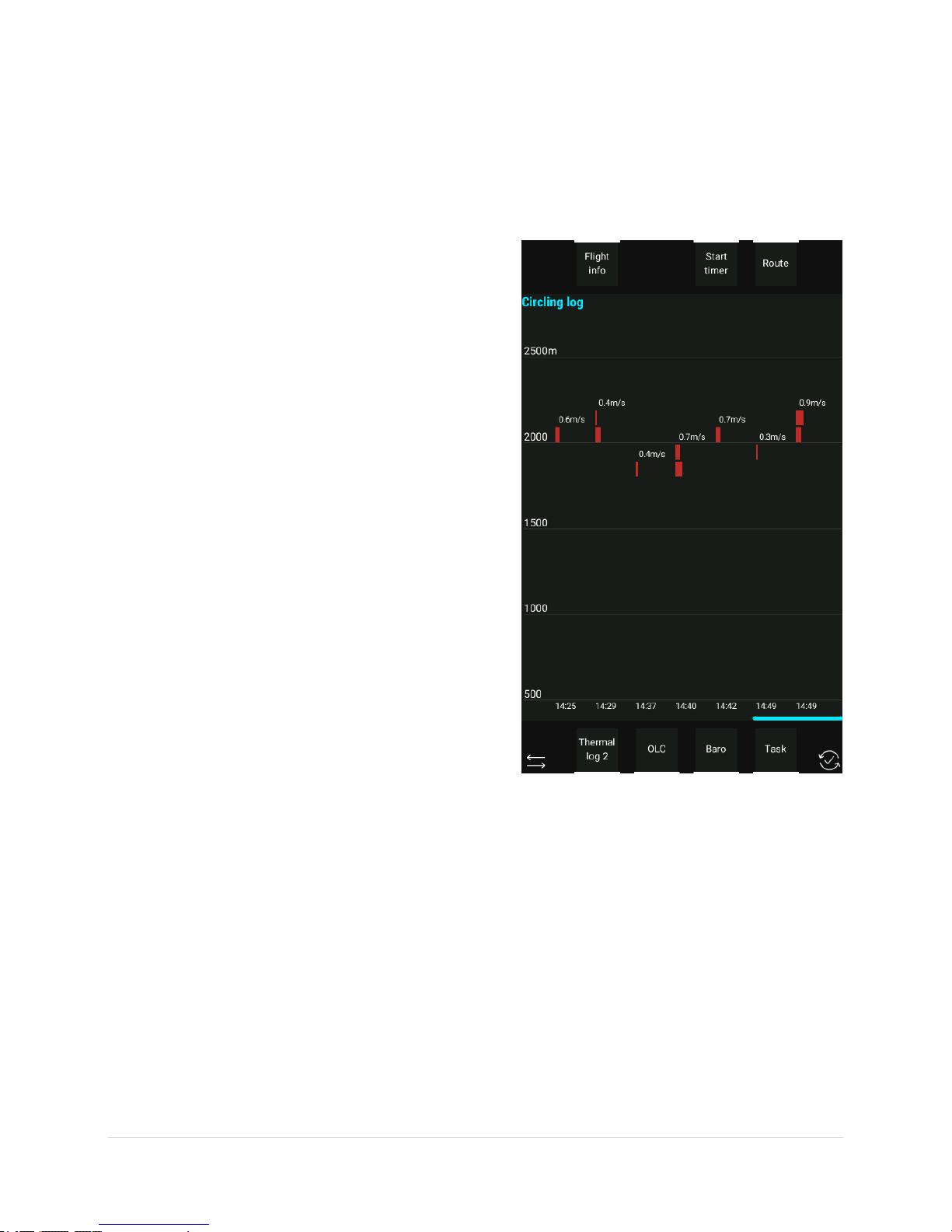
LX Zeus v4.0.2
End Flight function will close the flight so don’t use it during flight. Once End Flight has been commanded
the flight will end and the flight recorder (LX Eos/Era and Colibri II) will be forced to stop flight recording
and create an IGC file.
12.2.2.1 Thermal Analysis
There are two pages of thermal statistics, which are
selectable by pressing the screen buttons:
Thermals 1
Thermals 2
Thermals 1
Every column depicts a thermal. The column is sliced into
various colours and widths. The colours are blue, yellow
and red. These colours depend on the current MacCready
setting. If the thermal strength is below the MC setting,
then the column is blue, if it is above then the colour is
red. The yellow colour is around the MC setting (plus /
minus 20% of MC).
Thermals 2
This page shows all thermals of the flight; as a reference
the actual MC setting is shown also. The value depicted
corresponds to average thermal vario of an individual
climb from entering to leaving the thermal. The thermal
is only shown after a gain at least 100 m of altitude. The
dotted red line through the columns shows the MC
setting. This assists in determining a good MC setting.
94 | P a g e
Page 96

LX Zeus v4.0.2
Note!
Use Zoom rotary knob to scroll through the legs, as the
display is capable of showing only 4 legs at once.
12.2.2.2 OLC Calculation
OLC calculation is a calculation of OLC points according to OLC rules.
The current rules can be checked at:
http://www.onlinecontest.org/olc-2.0/gliding/cms.html?url=rules.
In general, the scoring software selects a departure point within the
unpowered part of the flight with up to 5 waypoints (turn-points)
and a finish point in such a way that the following two conditions are
fulfilled:
The raw point score (1 point per km) from the departure
point via all waypoints to the finish point is a maximum.
The departure altitude is not more than 1000 m higher than
the finish altitude.
To stimulate “area“ flying a FAI bonus is granted. For this purpose, the scoring program checks whether
FAI triangles can be fitted into the flight route and, if so, determines the largest such triangle for
calculating the FAI bonus.
There are three NavBoxes showing how many OLC kilometres have been achieved so far. One is labelled
OLC and shows the kilometres made to current point in the flight. The other one is labelled OLC HOME
and shows how many kilometres will be made if a return to the take-off point is achieved. The third
NavBox is OLC speed, which indicates the speed over the whole OLC distance flown.
12.2.2.3 Baro trace graph
A baro trace from take-off to the current position will be opened by pressing the button next to Baro.
Customisation of colours is possible at SETUP/USER INTERFACE/ STATISCTICS COLOURS.
12.2.2.4 Task Statistics
This page will open after pressing Task screen button. Task statistics are shown for the whole task and for
individual legs.
Speed: Average speed
Dist: Flown distance
Dur: Duration
V Avg: Average value of vario in thermals (circling)
Circ: Percentage of time circling (not flying straight)
Statistics are also available on 1st subpage on Task (TSK) navigation page.
95 | P a g e
Page 97

LX Zeus v4.0.2
12.2.2.5 Route
Route option is a feature showing the track already flown and the current task on the map. This enables
the pilot to see how precise the flying was and where detours were made.
12.2.2.6 Timer
To use a stopwatch, the timer function can be used which is located in Statistics. Timer manipulation is
as follows:
Select Start timer screen button and timer will start.
Stop timer by pressing Stop timer screen button.
Reset timer.
12.2.3 Follow me
The Follow me function can be accessed by long pressing the
Vario/Flarm button (the Flarm menu), selecting the Flarm object
we want to follow using the zoom rotary knob and pressing the
TSK/Move button, which selects the highlighted Flarm object.
12.2.4 Special functions
12.2.4.1 Event function
This function is active only if LX Eos and/or Colibri II is a
part of the system. A long press on the EVENT button will
send a command to connected flight recorders to activate
the event function. This means recording in shorter
intervals as a default for a limited time (default: event fix
interval: 1s; event repetitions: 20). Event settings are
under Setup > Logger.
96 | P a g e
Page 98

12.2.4.2 Marker setting
NOTE:
Marker function is possible only in TP navigation
If the pilot wants to mark a position of interest, for
example a suitable out-landing place, thermal hot spot…),
this can be done by activating the Marker function. The
process is very simple and doesn’t require much attention
by the pilot.
To mark a position the pilot should do as follows:
On TP navigation page, press Zoom rotary knob
Select screen button Add marker
The marker is shown as a yellow triangle on the map. Only
one marker can be active at any one time. To set a new
one simply repeat the procedure.
The marker is stored as user turn-point designated as
#MARKER. If edit TP function is used the #MARKER can be
converted into a normal TP. #MARKER can also be deleted
after using the Delete TP command. To navigate to
#MARKER point, simply select #MARKER under Select TP
dialog.
LX Zeus v4.0.2
97 | P a g e
Page 99

12.2.4.3 Pan mode
Note!
ARM command can be executed at any
time, even on the ground.
It is possible to move the position on the map using the
Volume and Zoom rotary knobs. Pan mode is available on
all three navigation pages (TP/APT/TSK). During the flight,
the tail and Flarm objects are displayed on the map in pan
mode.
To activate the mode, press button SELECT and choose
Pan mode screen button. It will then be possible to move
to the desired location on the map and, if GO TO is used,
the system will start navigation to a selected position on
the TP navigation page. The name of this selected point is
displayed as the current time.
A task in Pan mode can be created by accessing Pan mode
from the TSK navigation page. For more information see
chapter Creating a task in Pan mode.
LX Zeus v4.0.2
12.2.5 Task Start
Task start is quite a complex procedure, especially with a
high density of gliders where many of them intend to start
at nearly the same time. When the pilot intends to cross
the start line, a simple operation should be carried out:
Press on TSK button and press ARM screen button.
A message ARMED will appear on the display. The word
Armed will remain until the first line crossing. After
crossing the line the task will start automatically without
any further pilot interaction.
If the start line is crossed multiple times, the time of the last valid start will be used for statistics calculation.
Every next start is also displayed by a green message Task started at...
Under Settings > User interface > Track/destination settings the pilot can choose whether navigation is
aimed at the zone center or the zone closest point.
Disarm function will disable the Arm command.
98 | P a g e
Page 100

Note!
After Restart, the unit will change immediately into
ARM status, which means ready for next start.
Note!
In the event that the pilot crossed the start line and forgot to execute ARM before that, execution of
NEXT TP function will solve the problem. Navigation to the first turn point will then be offered and the
statistics page will become available. LX Zeus will find last valid start line- cross and use it for statistics.
12.2.5.1 Start Conditions / Limitations
Some competition rules prescribe limitations
(restrictions), which should be respected before the start
and also while crossing the start line. After a short press
on TSK/MOVE screen button, Limitations will appear.
Select Limitations screen button to enter limitation setup
menu. Limitations are divided to:
Gate time
Before start
Start conditions
LX Zeus v4.0.2
Gate time sets the time when the start line will be opened.
Calculated time will be time set on LX Zeus (UTC or UTC
offset time). LX Zeus time is by default set to UTC time.
Time offset can be changed under Setup > Locale > UTC
offset.
Below start altitude and time can be set. The glider should
be below the selected altitude when starting.
Start conditions can be limited to start altitude and
ground speed.
A limitation indicator will appear on the screen (only on TSK
screen). First the pilot needs to add the Limitations indicator to the screen by modifying the TSK layout.
Go to Setup > Layout and edit TSK navigation page.
12.2.5.2 Task Restart
If the pilot decides to restart the task, having already started, it is possible to do this by executing the
Restart function. It is accessed by pressing TSK/MOVE button and then pressing the Restart screen button.
After pressing Restart, the task will be reset (doesn’t matter on which leg) and a new start can be
performed. Also, the task statistics will be reset.
99 | P a g e
 Loading...