

Page 1
LX Navigation d.o.o. LX 7007 C May. 30th 2012
- 1 -
LX 7007 C
Users manual V 3.0
(Also valid for LX 7007 CB and LX 7007 Compact C/CB)
LX navigation
d.o.o.
Tkalska 10 SLO 3000 Celje
+ 386 3 490 46 70 + 386 3 490 46 71
support@lxnavigation.si http://www.lxnavigation.si
Page 2

LX Navigation d.o.o. LX 7007 C May. 30th 2012
- 2 -
1 GENERAL....................................................................................................................- 5 -
1.1
Technical data...................................................................................................................................... - 6 -
1.2
Options ................................................................................................................................................. - 7 -
1.2.1 Two seater configuration................................................................................................................... - 7 -
1.2.2 Remote control .................................................................................................................................. - 7 -
1.2.3 Flarm ................................................................................................................................................. - 7 -
1.3
LX 7007 Compact C and LX 7007 Compact CB ................................................................................ - 7 -
2 SYSTEM DESCRIPTION .............................................................................................- 8 -
2.1
Rotary switches and keys (buttons).................................................................................................. - 8 -
2.1.1 ON/START button - Switching the Instrument ON and OFF ............................................................ - 8 -
2.1.2 MODE selector (rotary switch) ................................................................................................... - 9 -
2.1.3 AUDIO Volume selector .................................................................................................................... - 9 -
2.1.4 UP/DOWN selector (rotary switch) .............................................................................................. - 9 -
2.1.5 ZOOM Rotary switch ......................................................................................................................... - 9 -
2.1.6 ENTER button ................................................................................................................................... - 9 -
2.1.7 ESC/OFF button................................................................................................................................ - 9 -
2.1.8 EVENT button ................................................................................................................................... - 9 -
2.1.9 MC and BAL buttons ......................................................................................................................... - 9 -
2.2
Operating modes ............................................................................................................................... - 10 -
2.3
SETUP................................................................................................................................................. - 11 -
2.3.1 Main Setup (First level) ................................................................................................................... - 11 -
2.3.1.1 QNH RES (QNH and Safety Altitude input) ........................................................................... - 11 -
2.3.1.2 PILOT ..................................................................................................................................... - 12 -
2.3.1.3 LOGGER (Input of flight recorder parameters) ...................................................................... - 12 -
2.3.1.4 TRANSFER ............................................................................................................................ - 14 -
2.3.2 SYSTEM SETUP (Second level) .................................................................................................... - 15 -
2.3.2.1 Glider ...................................................................................................................................... - 15 -
2.3.2.2 Airspace (Selection of airspace section and warning criteria) ............................................... - 15 -
2.3.2.3 AUDIO Vario (Adjustment of audio ) ..................................................................................... - 15 -
2.3.2.4 Audio Alarm ............................................................................................................................ - 16 -
2.3.2.5 Turn points.............................................................................................................................. - 16 -
2.3.2.6 Task Observation Zone .......................................................................................................... - 17 -
2.3.2.7 Graphics ................................................................................................................................. - 17 -
2.3.2.8 TE comp. ................................................................................................................................ - 19 -
2.3.2.9 Altitude warning ...................................................................................................................... - 19 -
2.3.2.10
LCD Indicator ..................................................................................................................... - 19 -
2.3.2.11
Units ................................................................................................................................... - 20 -
2.3.2.12
Voice .................................................................................................................................. - 21 -
2.3.2.13
Flarm .................................................................................................................................. - 21 -
2.3.2.14
Local time ........................................................................................................................... - 21 -
2.3.2.15
NMEA output...................................................................................................................... - 21 -
2.3.2.16
User Port ............................................................................................................................ - 22 -
2.3.2.17
GPS Input........................................................................................................................... - 22 -
2.3.2.18
ENL (Engine noise level).................................................................................................... - 22 -
2.3.2.19
Hardware............................................................................................................................ - 22 -
2.3.2.20
About .................................................................................................................................. - 22 -
2.3.2.21
Service ............................................................................................................................... - 22 -
2.3.2.22
Firmware update ................................................................................................................ - 23 -
2.4
Navigation Functions ........................................................................................................................ - 24 -
2.4.1 GPS Page ....................................................................................................................................... - 24 -
2.4.2 NEAR AIRPORT ............................................................................................................................. - 24 -
Page 3

LX Navigation d.o.o. LX 7007 C May. 30th 2012
- 3 -
2.4.3 APT Airports, TP Turn Points.......................................................................................................... - 25 -
2.4.3.1 APT / TP Navigation sub pages ............................................................................................. - 25 -
2.4.3.2 Airport Selection ..................................................................................................................... - 26 -
2.4.3.3 Turn point Selection................................................................................................................ - 27 -
2.4.4 Task................................................................................................................................................. - 27 -
2.4.4.1 Task management.................................................................................................................. - 27 -
2.4.5 Statistics .......................................................................................................................................... - 30 -
2.4.5.1 Flight statistics ........................................................................................................................ - 30 -
2.4.5.2 Task statistics ......................................................................................................................... - 30 -
2.4.5.3 Log Book ................................................................................................................................ - 30 -
2.5
Variometer and altimeter .................................................................................................................. - 31 -
2.5.1 Smart Vario description ................................................................................................................... - 31 -
2.5.2 Altimeter .......................................................................................................................................... - 32 -
2.5.2.1 IGC barogram recalibration procedure ................................................................................... - 32 -
2.5.3 Speed command ............................................................................................................................. - 32 -
2.5.4 Final glide calculation ...................................................................................................................... - 32 -
2.5.4.1 Final glide after using of FAI finish setting ............................................................................. - 32 -
3 FLYING WITH THE LX 7007 C..................................................................................- 33 -
3.1
Flight preparation on ground ........................................................................................................... - 33 -
3.1.1 Single pilot option ............................................................................................................................ - 33 -
3.1.2 Multipilot option ............................................................................................................................... - 33 -
3.1.3 SET Elevation (take off elevation input).......................................................................................... - 33 -
3.1.4 Preparation of data base................................................................................................................. - 34 -
3.1.5 Preflight check................................................................................................................................. - 34 -
3.1.6 Preparing a task .............................................................................................................................. - 34 -
3.1.6.1 AAT (assigned area task) ....................................................................................................... - 34 -
3.1.7 Task Start ........................................................................................................................................ - 35 -
3.2
Flying a task....................................................................................................................................... - 35 -
3.2.1 Flying a speed task ......................................................................................................................... - 35 -
3.2.2 Flying an AAT.................................................................................................................................. - 35 -
3.2.2.1 Start ........................................................................................................................................ - 35 -
3.2.2.2 Inside AAT sector ................................................................................................................... - 35 -
3.3
Flarm functions.................................................................................................................................. - 36 -
3.3.1 Traffic monitor in graphic page ....................................................................................................... - 36 -
3.3.2 Flarm “Traffic Radar” ....................................................................................................................... - 37 -
3.3.3 Airspace monitoring during flight..................................................................................................... - 38 -
3.3.3.1 Airspace Management ........................................................................................................... - 39 -
4 INSTALLATION .........................................................................................................- 40 -
4.1
Mechanical layout.............................................................................................................................. - 40 -
4.2
Installation of main unit .................................................................................................................... - 40 -
4.3
Pneumatic connections .................................................................................................................... - 41 -
4.4
Power connection.............................................................................................................................. - 42 -
4.5
Vario/SC external switch installation .............................................................................................. - 43 -
4.6
Installation of PDA units ................................................................................................................... - 43 -
4.7
Installation of options ....................................................................................................................... - 44 -
4.8
Wiring schematics (also valid for LX 7007 Compact CB).............................................................. - 45 -
Page 4

LX Navigation d.o.o. LX 7007 C May. 30th 2012
- 4 -
4.8..................................................................................................................................................................... - 46 -
4.8.1 Wiring LX 7007 Compact C............................................................................................................. - 46 -
4.8.1.1 GPS connection...................................................................................................................... - 47 -
4.8.2 Wiring LX 7007 Compact C B ......................................................................................................... - 47 -
4.8.2.1 GPS connection...................................................................................................................... - 47 -
Page 5
LX Navigation d.o.o. LX 7007 C May. 30th 2012
- 5 -
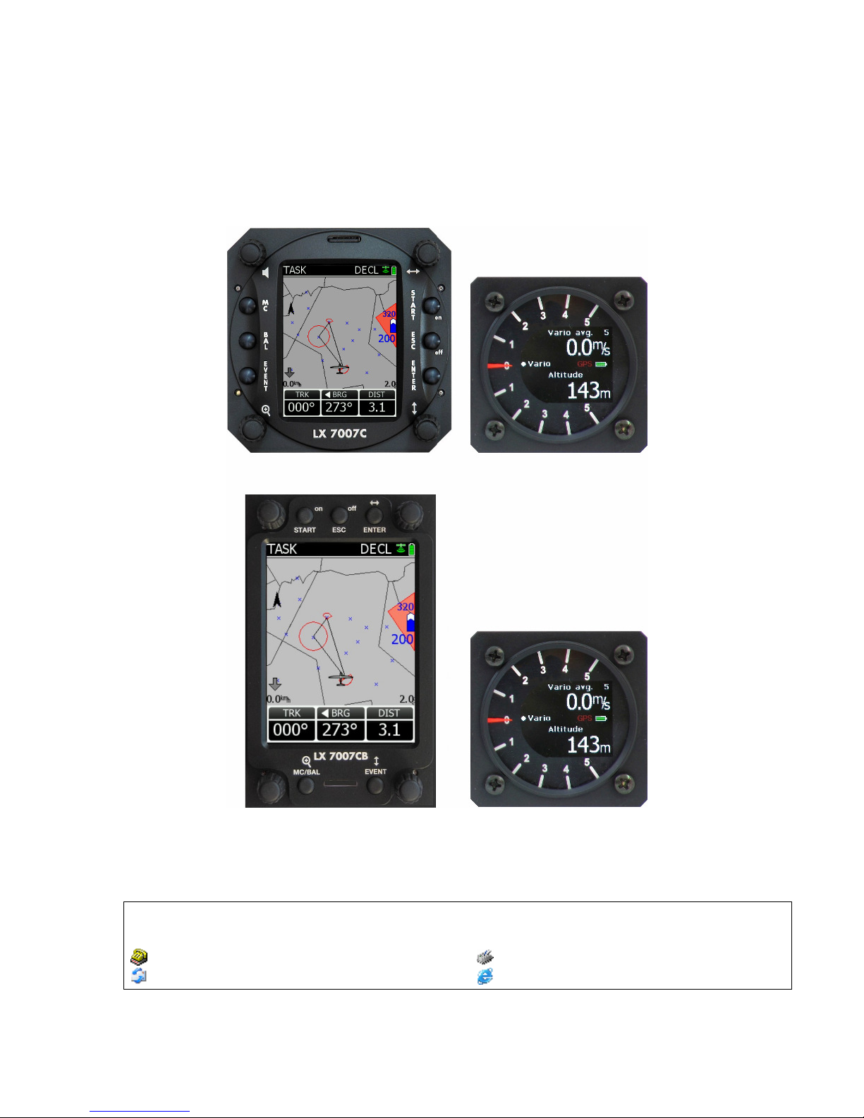
1 General
The unit consists of two units, one 80 mm unit (LX 7007 DU) and one 57 mm unit (USB D). The 80 mm unit is
a master unit and contains a high-resolution colour display, 6 push buttons and four rotary switches. The 57
mm unit is a vario unit and does not have any controls on it’s front panel. All necessary commands are sent
from the master. Sensors to measure altitude and IAS are located in the vario unit. The Vario unit display
consists of a mechanical needle, which is mainly used as vario indicator, and a colour graphic display, which
is configurable in setup.
LX 7007 C
LX 7007 CB
The unit comes in two versions LX 7007 C can be fitted into 80 mm standard cut out and LX 7007 CB has a
bigger (3.5 inch) display which requires a larger cut-out. The functions of both units are identical.
Vario functions include:
• Vario with audio, Netto, Relative (Super Netto) and Average
• Smart vario
• Speed command
• Final glide calculator
• TE compensation is selectable for either pneumatic TE tube, or electronic TE
• Altitude gain indicator
• Total averager of last thermal
•
Page 6

LX Navigation d.o.o. LX 7007 C May. 30th 2012
- 6 -
Navigation functions include:
• Airport and airspace database for Europe or USA, an almost unlimited number of AS sections can be
stored
• Turn points in .cup format, an almost unlimited number of files can be stored, up to three active files can be
used at the same time
• A wide range of task options, either imported as a part of .cup files, user created in addition to one declared
task
• Statistics, flight statistics and task statistics
• Display of nearest airports and out landing fields
• Support of AAT (assigned area task)
• Distance measuring equipment in TP and APT mode
• Multi pilot function (storing of 100 pilots names with their individual settings)
Flight recorder functions include:
• Integral pressure transducer based on 1013 mb level, for altitude recording
• Integral Engine Noise Level sensor
• Memory to store typically 100 flight hours (hardly depends on settings)
• Digital and mechanically security device to ensure high level of data security
Interfaces:
• PDA interface powers and sends data to a PDA. Programs supported:
SeeYou Mobile, Winpilot Version 7 or higher, Navigator, LK 8000
• User interface powers and sends NMEA at various baud rates, connection to a transponder possible.
• SD Card interface for data transfer and firmware update
• IGC interface to connect and power Colibri or LX 20. The connector pin out corresponds to the IGC
standard and may be used to power the LX 7007 and to communicate with PC also, by the use of a
standard Colibri Power adaptor. Whilst training, this input can be used to connect to Condor flight
simulator.
Options:
• Integral Flarm, collision avoidance system
• Remote control, for both seats
• Two seater configuration
• Compass
• Secondary LCD colour vario indicators
• Voice Module, to give voice warnings and information.
1.1 Technical data
• Power input 10-16 V DC
• Consumption: 210 mA @ 12V (without audio and options), 260 mA with Flarm option
• 80mm (3") standard Aircraft cut-out for LX 7007 DU
• 57mm (2 1/4") standard Aircraft cut-out for USB D Length 120 mm (incl. connector)
• Three physically separated com. Ports:
-PDA port with 5V power supply delivers NMEA and task data to PDA and allows data transfer
- IGC com port with IGC standard connector, suitable to connect Colibri or LX 20 or PC
- User port for GSM Modem connection
• Drives the following PDA programs: SeeYou Mobile, Navigator, LK 8000, and Winpilot….
• PDA data exchange with ConnectLX, ConnectMe, Navigator
• 16 Channel GPS receiver
• SD card interface
• External speaker
• System bus enables connection to a wide range of options
• Built in fuse to prevent damage in the event of a short on the 485 bus
• Data compatible with LX 20 and Colibri
• IGC approved flight recorder
• Weight: apr. 800g
Page 7

LX Navigation d.o.o. LX 7007 C May. 30th 2012
- 7 -
1.2 Options
By use of a bus system a wide range of optional interfaces can be easily connected to the basic configuration,
without any significant installation work. The LX 7007 system bus is extended simply by use of 485 splitting
units, which allow plug and play connection of additional devices. The following units can be connected to LX
7007 system bus:
• Second seat device
• Remote control, for both seats
• Flarm option (integral part, not bus connected)
• Secondary vario LCD vario indicators (unlimited number)
• Electrical compass device
• Voice module
1.2.1 Two seater configuration
A unit installed in the rear seat of the glider, is powered and receives all it’s data from the main unit. The
communication between both units is exclusively via 485 system bus. An automatic TP and TSK update will
follow after each power on, the airspace update is done on pilot demand. See LX 7007 D manual for details.
1.2.2 Remote control
An extremely ergonomic lather coated handle which includes 8 push buttons to operate LX 7007 and also two
additionally buttons with open wires. This two buttons can be used for instance as PTT for radio and SC/Vario
changeover command. Using a two seat configuration, two remote units can be installed to control the front and
rear seats separately.
1.2.3 Flarm
Flarm electronics is completely compatible to original Flarm units and an integral part of LX 7007 C DU, if
ordered as an option. All necessary connectors are available at the back of the unit (Flarm update port, Flarm
External Indicator, Flarm antenna), which guaranties the same features as an original Flarm device. It is very
important to point out that the whole system uses only one GPS receiver and therefore offers a low power
solution. One Flarm External display is part of the delivery; extension to second seat is possible.
1.3 LX 7007 Compact C and LX 7007 Compact CB
Both units are derivatives of the LX 7007C & LX 7007 CB respectively. Configuration is the same as for LX
7007C, but there is no in built GPS. The following functions differ on the LX 7007 Compact C and LX 7007
Compact CB:
-no approved flight recorder (there is recorder but it cannot be used as an official IGC file)
-external GPS input plug and play compatible with Colibri, LX 20, Colibri II, Flarm)
-vario electronics built into main unit (not valid for CB)
Unit operation is almost the same as the LX 7007 C, so the same manual can be used. Functions that are
different are marked.
Page 8
LX Navigation d.o.o. LX 7007 C May. 30th 2012
- 8 -
Audio adj.
Mode selector
UP/DOWN selector
Zoom
2 System description
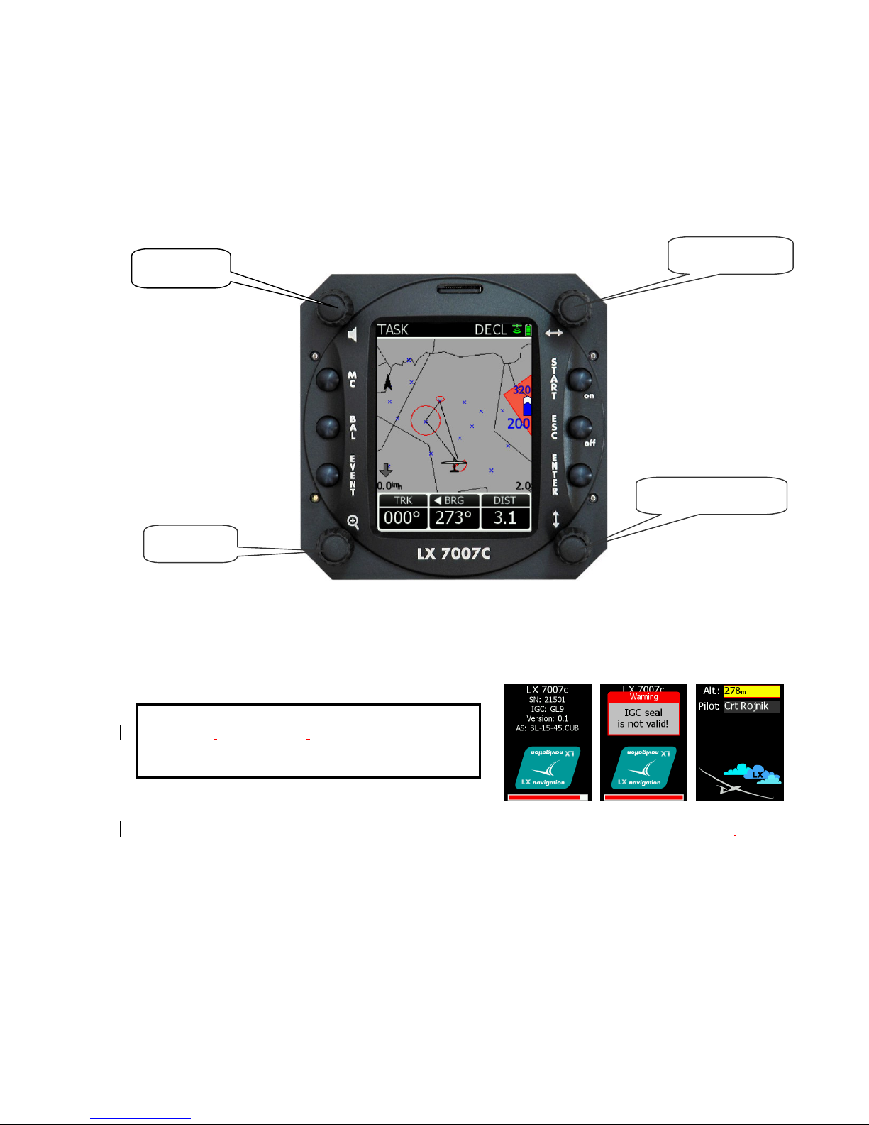
2.1 Rotary switches and keys (buttons)
The following controls are mounted on the front face of the LX7007 C
• Four rotary selector switches
• Six push buttons
2.1.1 ON/START button - Switching the Instrument ON and OFF
The ON/START button is multifunctional. If the instrument is not already powered up, a short press on the
ON/START button will switch the instrument ON. The following initial pages will appear after power on.
A long press (about 2 seconds) during operation will change to next turn point in Task mode, but only if the
glider is inside the TP sector. This is only valid if the changeover preset has been set to ‘not automatic’.
In TP a short press will start storing of present position to become a new turn point.
During edit a short press on Start will move cursor one step back.
The unit is equipped with a facility of storing up to 100 pilot names. Pilot selection can be done by rotating the
Up/Down knob. ‘Enter’ will select the pilot and the unit will change over to the GPS status page.
There are some other functions connected with Start bottom, please see further chapters.
After booting is finished take off airfield elevation and pilot selection are offered.
Important!
Message ‘Seal Not Valid’ is a warning that the IGC
security device is out of order, no message means
correct security device.
Page 9

LX Navigation d.o.o. LX 7007 C May. 30th 2012
- 9 -
2.1.2 MODE selector (rotary switch)
The mode selector is used to change modes of operation. This switch has the highest priority in the system.
Whenever it is operated, a mode change will occur.
2.1.3 AUDIO Volume selector
This knob is exclusively used to adjust audio volume.
2.1.4 UP/DOWN selector (rotary switch)
This rotary switch has a lower priority than the mode selector switch and is active all the time in the selected
mode. It is mainly used for selecting sub menus during navigation and to scroll in the edit menu.
2.1.5 ZOOM Rotary switch
This is a multifunctional rotary switch. While its main function is to change the zoom level in the graphic
mode, it can also be used as follows:
• If an error is made during editing, it is possible to move the cursor back by rotating this knob. This can only
be done if 'editing' is active which is shown by the cursor blinking
• ZOOM can be used for numeric inputs (elevation, sectors….) to speed the process, using ZOOM instead of
Up/Down will increase in steps by a factor 5
• Some special functions of Zoom knob will are described in next chapters.
2.1.6 ENTER button
The main function of this key is confirmation, and to start edit procedures.
2.1.7 ESC/OFF button
This is a multifunctional key, which has two main functions. If it is pressed and held for a few seconds, then the
instrument will start turning OFF sequence. A count down will show time in seconds until the unit will switch off.
A new press on any key during count down will interrupt switching off process.
If a short press is made, then the button has the following functions:
• The display will jump to the menu of the next higher level (in edit only)
• During alpha-numeric input with the cursor active (blinking), ESC confirms the whole line (It is not
necessary to keep pressing ENTER )
• Some special functions can be activated using ESC as described in subsequent paragraphs
2.1.8 EVENT button
Activates so called event function of flight recorder.
Event is a multifunction button, a short press will activate Flarm traffic information page and a longer press
(apr.2 seconds) will activate flight recorder Event function.
2.1.9 MC and BAL buttons
Pressing of MC button will activate the Mc Cready (MC) input screen. The value is changed with the UP/DOWNselector. After second press Ballast can be input. This form of input should be used with the LX 7007 CB, as
there is no Bal button.
Note!
If Competition mode has been activated in Setup Pilot (only 3 modes available) then a long press on MC
button deactivates the function.
Ballast button is multifunctional, first press enables ballast input, the second press activates so called Bugs
input, degradation of best glide ratio.
Page 10
LX Navigation d.o.o. LX 7007 C May. 30th 2012
- 10 -
2.2 Operating modes
MODE
Near airport Airport Turnpoint Task Log book / statistics Setup GPS
Navigation menus (APT, TP and TSK) have sub menus, which can be selected using the Up/Down rotary
switch.
Sub pages of task mode
GPS GPS status, no inputs possible
NEAR Near airport, select one airport or land able turn point, no further inputs are possible
APT Navigation and selection of airports
TP Navigation, selection and editing of turn points
TSK Navigation, selection and editing of tasks
STAT Flight statistics and logbook
SETUP has two levels. The first level enables direct input of individual parameters. By entering into SYSTEM
SETUP global parameters can be adjusted.
Note!
After activation of Competition Mode only three modes are available, TSK, TP and Statistics. See capture 2.3.
Page 11
LX Navigation d.o.o. LX 7007 C May. 30th 2012
- 11 -
2.3 SETUP
The SETUP is divided into two parts, First level (non system data) and the Second level (system data). Inputs
done in the first level are connected with daily work, the settings done in the second level may change system
characteristics and as such are significant.
2.3.1 Main Setup (First level)
All options are selected with the UP/DOWN () switch and can be entered at any time;
The system settings are not affected. The Menu has six items, starting with QNH Reserve
and ending with System which allows entry into system setup.
Once the desired option has been selected, press ENTER to access the sub-menu.
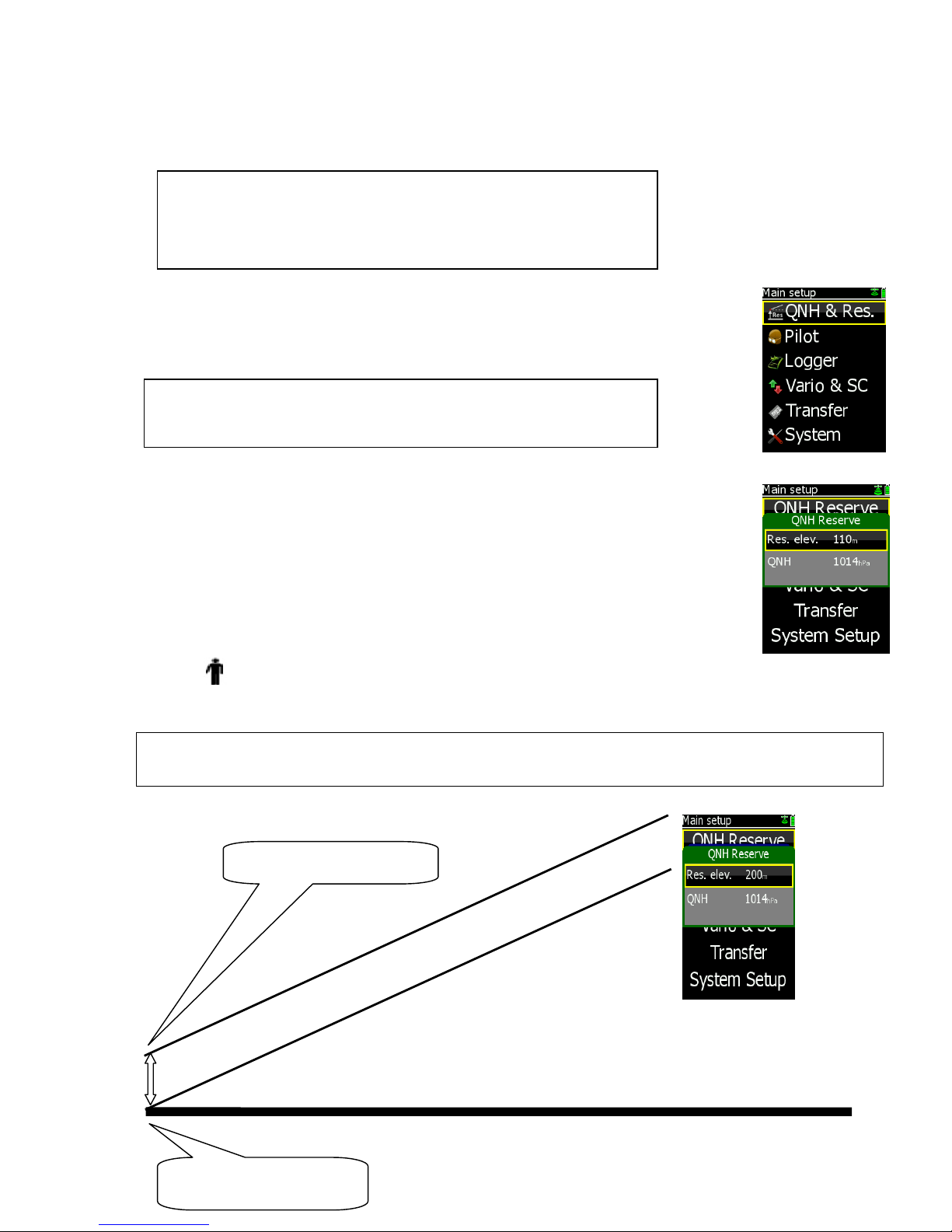
2.3.1.1 QNH RES (QNH and Safety Altitude input)
Input Procedure:
• Use the UP/DOWN selector to choose the item it is required to change
(QNH, ALT.R.)
• Press ENTER
• Use UP/DOWN to select the value required and press ENTER to input it
• Once all changes are complete, press ESC top return to SETUP menu
ALT.R : This setting is used to input the altitude reserve or safety altitude. Setting 0 means that no
altitude reserve is set for the final glide. After input the final glide is shifted and the arrival is calculated to the
altitude set in the reserve menu.
Note!
Even after input of a reserve the final glide director will show you 0 glide deviation if the glider position is on the
shifted glide.
Finish line arrival on 0 m
Finish line arrival on 200 m
Note!
Some settings are so called global settings, not connected to pilot and
second parts are so called local settings. Local settings belong to pilots.
Local settings are accompanied with a man silhouette which to make
understanding more easy.
Note!
TRANSFER offers no inputs, but enables data transfer LX 7007 C to SD
Card, PDA, Colibri or PC.
Page 12
LX Navigation d.o.o. LX 7007 C May. 30th 2012
- 12 -
QNH: Initial status after power on is undefined (- - - - - ). If the pilot wants to adjust the altitude reading due to
pressure changes during the flight, then an initial input of the actual QNH is required. Input is done with
Up/Down and ZOOM. This procedure can only be made on the ground, after take off no initial input is
possible. Following QNH input on the ground, then an update during the flight is possible.
FAI finish: if a badge flight is intended to be flown this menu could
be used to adapt arrival altitude relating to IGC rules. After input
Yes the final glide will be adequately shifted if the start was above
1000m. This is valid only in task mode.
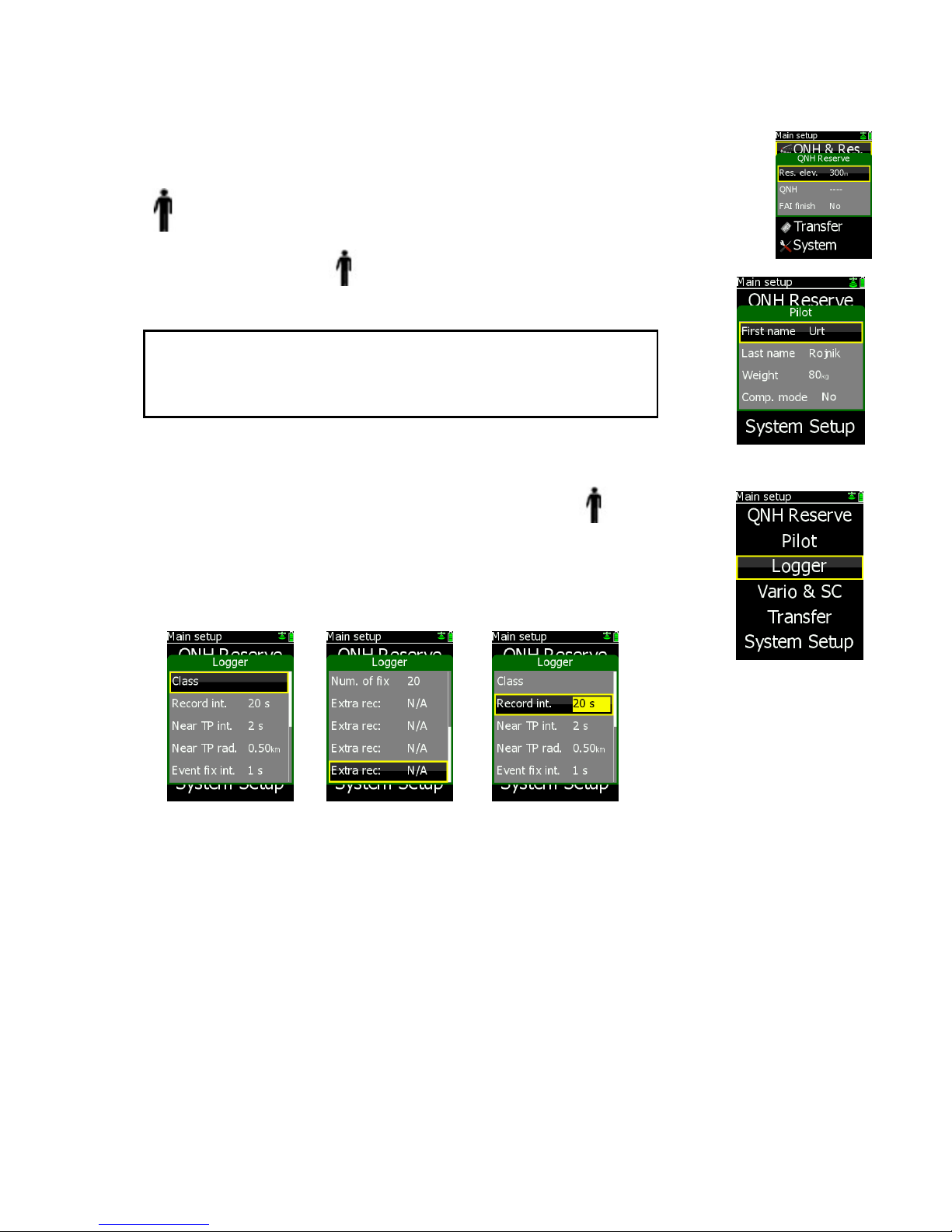
2.3.1.2 PILOT
Input of pilot personal data is possible with this menu.
New input is done simply following an update of existing data and store as a new pilot.
Competition mode is linked to the pilot, so if one pilot has activated this
function then the function will not affect other pilots. For future a pilot
list transfer file transfer via SD card is foreseen.
2.3.1.3 LOGGER (Input of flight recorder parameters)
The flight recorder is fully approved by the IGC (A sub-committee of the FAI)
and will produce secure flight records that are acceptable for all kind of FAI
badge flights and also world records.
After selecting LOGGER and pressing ENTER, the following
flight recorder settings are accessible.
Class input means input of the glider class for instance Standard. For safety reason faster recording interval can
be used close to the turn point. All necessary parameters are to be defined in near TP and near radius. IGC
regulations require more frequent recording after a so called “Event function” has been activated (press the
event button long). After event activation the recording interval will follow setting in “Event fix int”. Number of
additional fixes is defined in Num. of fix.
Important!
Setting Competition mode (Y) will reduce selection of navigation modes.
Only Task, TP and Statistics will remain active. To recall standard
configuration, use long press on MC.
Page 13
LX Navigation d.o.o. LX 7007 C May. 30th 2012
- 13 -
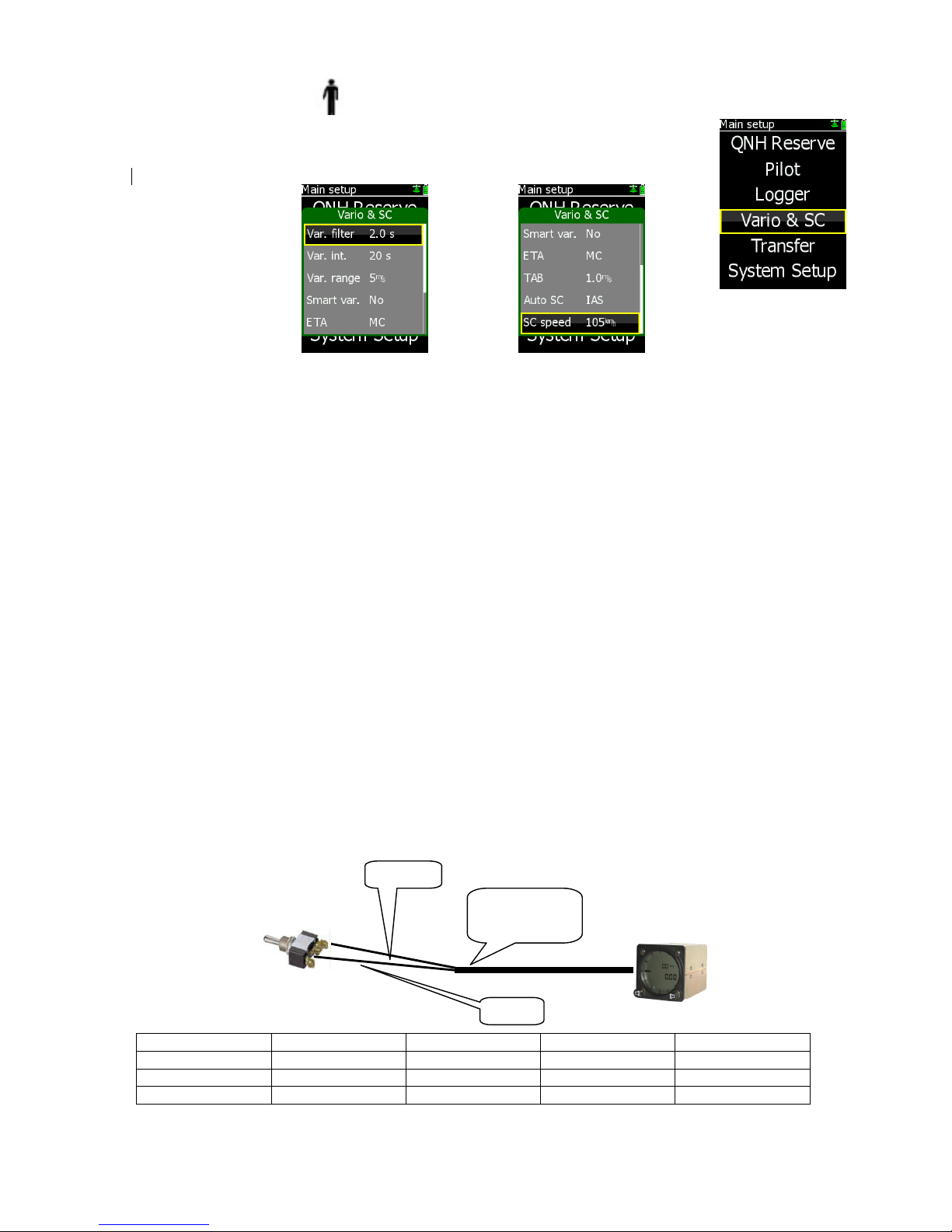
2.3.1.3.1 Vario & SC
Vario & SC allows the setting of the variometer and speed
command. All vario functions are exclusively executed in vario unit
(AU, USB or USB D), but the commands are sent from this menu.
• Var. filter: This sets the time constant of the vario from 0.5sec up to 5 sec; the default setting is 2.0
seconds (higher figures results in a slower reaction of the vario needle)
• Var. int: This setting defines integration period for the averager in seconds; default is 20
seconds
• Var.range: This sets the full scale range of the vario
• Smart var. : S.v. means Smart Vario, giving four levels of additionally dynamic damping of the vario
indication the function can enabled or disabled, see chapter 2.5 for details
• ETA: This setting selects the parameter, VAR (daily vario average) or MC, (actual) that is
used to calculate the Estimated Time of Arrival. When flying a programmed task, the
calculation takes account of the unflown portion of the task , around any TPs or APTs
not yet reached
• TAB: This setting defines the width of the audio dead band in speed to fly mode
• Auto SC: This option defines the conditions by which the instrument is switched between vario
and speed command
OFF: Switching is possible exclusively by an external switch, connected to the LX 7007
AU or USB unit
GPS: When the GPS detects that the glider is circling an automatic change over to
vario mode will happen after approximately 10 seconds. Detection of straight flight will
cause a change to speed command.
IAS: When the IAS exceeds a pre-set value. The IAS at which switching occurs can be
selected in 5 km/h steps from 100 up to 160 km/h (or the equivalent in knots or mph)
• SC Switch: if external switch is used for vario to SC change over, take note of the following:
The LX 7007 C has a connection for an external speed command switch, which is wired to LX 7007 vario unit.
Using an external switch it is possible to switch between SC and Vario manually. Setting the SC Switch to ON
means that closing of the switch will cause SC mode, and setting SC INPUT to OFF means that closing the
switch will select Vario mode. There is a third option by setting SC INPUT to Taster and connecting a push
button each press will toggle between SC and Vario (obligatory setting when using the LX Remote).
Wire Shield
Open
Setting: ON Staus: VAR
Wire Shield
Closed
Setting: OFF Staus: SC
Wire Shield
Closed
Setting: ON Staus: SC
Wire Shield
Open
Setting: OFF Staus: VAR
SC, Marked
cable
Schield
Wire
Page 14
LX Navigation d.o.o. LX 7007 C May. 30th 2012
- 14 -
Note!
The external switch wired to LX 7007 AU/USB –D has an absolute priority and will override all other switching
methods.
• WIND/COMPASS: N.C. means compass option not connected. When the optional compass module is
installed, the instrument uses magnetic track to make an additional wind calculation.
The calculation requires the glider to fly straight for a specified period, which is set in
this option. The default is 15 seconds, but the longer the period, the more accurate is
the calculated wind.
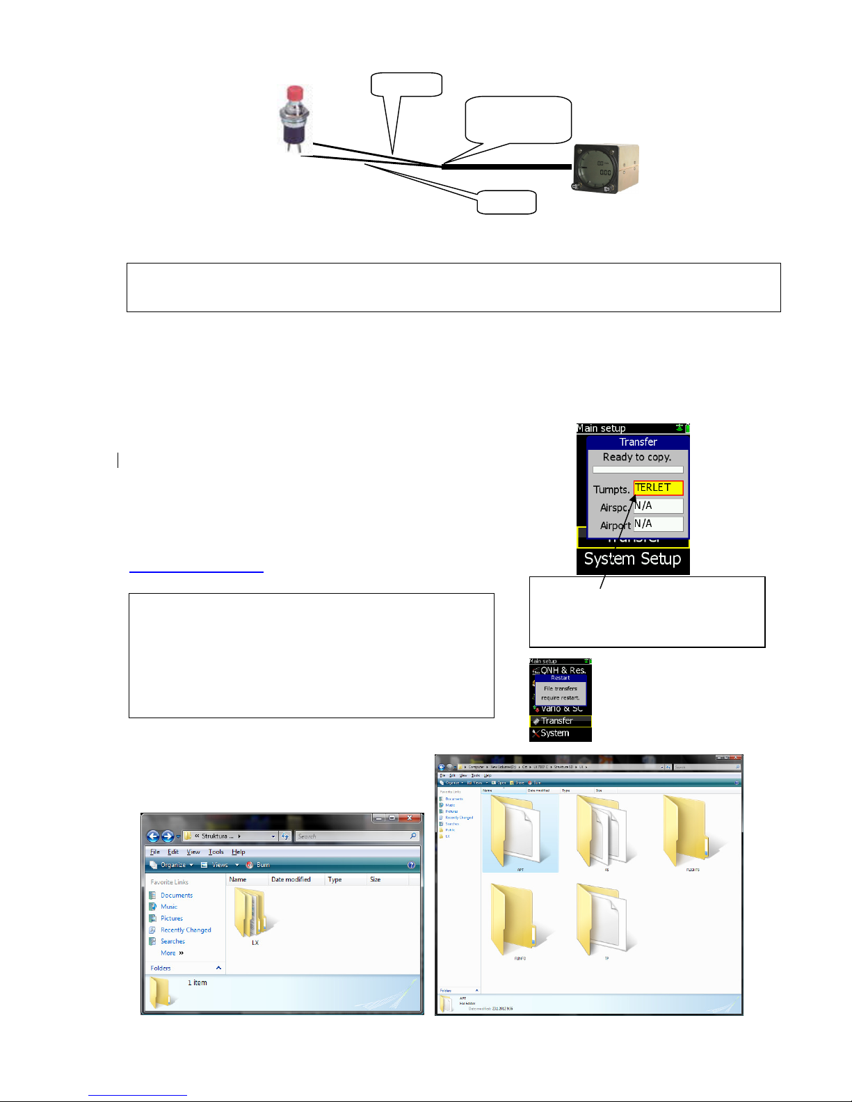
2.3.1.4 TRANSFER
Transfer makes it possible to input Turn point data, Airport data
and Airspace data into LX 7007 C. The files should be copied
to an SD card by PC.TP files format should be .cup,
airspace .cub and airports in .af format. Flight info
(pilot and declaration) should be in .hdr (LX navigation format).
Item FlarmNet which is positioned below Airport icon can be used
for input of Flarm IDs. This makes possible to recognize Flarm objects
under their custom names. The file is available on
http://www.flarmnet.org. Download LX Navigation variant.
Structure of LX folder in which individual
files should be copied by PC.
SC, Marked
cable
Shield
Wire
Note!
After copying into the memory of the unit, the airspace and
the turn point files should be activated in System setup
under Airspace & Turn points respectively. Airport file
becomes immediately active after copy sequence is
completed.
After transfer process, a controlled power off will follow.
Select item of interest, press enter
(item will become yellow) and select
file by ↕. After enter the file will be
copied to LX 7007 internal memory.
Page 15
LX Navigation d.o.o. LX 7007 C May. 30th 2012
- 15 -
2.3.2 SYSTEM SETUP (Second level)
After entering the System Setup, a further 19 system settings are available.
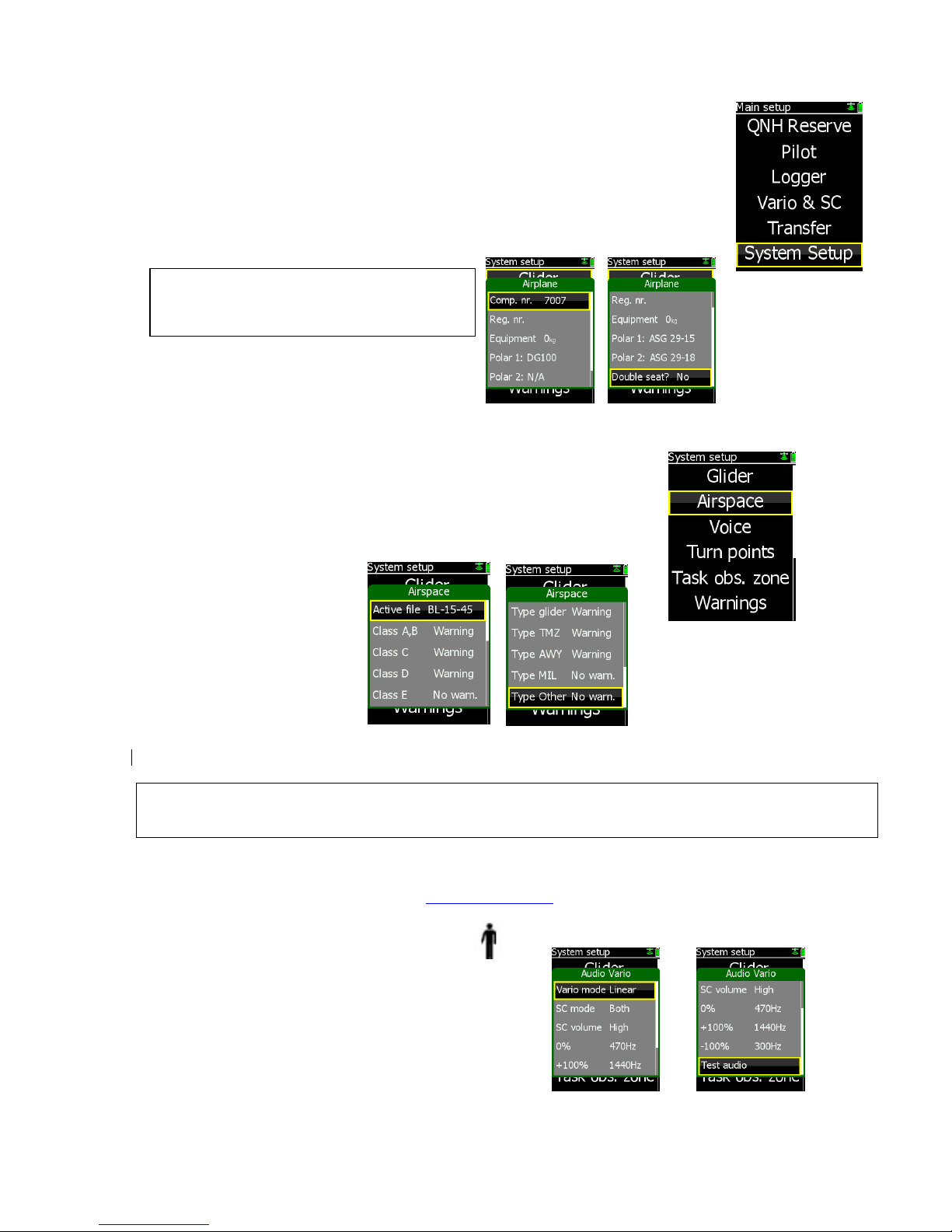
2.3.2.1 Glider
All data connected to glider should be entered in this menu.
There is space to store two glider polars for instance 15 m
and 18 m version.
Equipment means in fact luggage, this input will be
also taken in account in the ballast calculation.
2.3.2.2 Airspace (Selection of airspace section and warning criteria)
The unit is capable of storing an almost unlimited number of airspace sections.
Selection of suitable area should be done by pilot after use of this menu.
Airspace file uploading to LX 7007 C is exclusively via SD card. Active file
menu will show you all stored airspace sections. Select section of interest
by Up/Down.
Input of Warning Yes will produce an audio warning close to the airspace. See also chapter
Graphic/Appearance.
Note!
LX 7007 C is able to use only one airspace section at the same time, the section should be enabled in Airspace
menu of System Setup, also during the flight.
Creation of custom airspace files
To prepare custom airspace, in .CUB format, use our special tool for airspace creation and edit, called
LxAsbrowser, which is available for free on www.lxnavigation.si or on LXe CD.
2.3.2.3 AUDIO Vario (Adjustment of au
dio )
A wide variety of audio variants can be configured by user:
Use Test audio function after every change to hear the
difference.
• VARIO mode: select type of vario audio, use test function to perform
• SC mode: defines interrupted tone (piep, piep) presence in SC, regarding to needle position
Note!
If two polars are entered, both of them will be
offered when booting.
Page 16

LX Navigation d.o.o. LX 7007 C May. 30th 2012
- 16 -
• SC: VOL H audio volume will be increased or decreased during speed command period set (H) or ( L)
• 0%: tone frequency at 0 m/s
• +100%: tone frequency at full + deflection
• -100%: tone frequency at full – deflection
2.3.2.4 Audio Alarm
The unit produces an audio alarm on reaching certain confirmation points.
This screen allows the parameters of the audio to be configured. Also
Entering airspace will be accompanied with an audio warning.
Setting in this menu makes it possible to customize the audio tone.
2.3.2.5 Turn points
This section is about some settings relating to turn points and
TP file management. The unit accepts .CUP file format
And the store capacity is almost unlimited.
Input of TP files is exclusively via SD card.
Near rad.: defines radius around the turn point which will be taken as a confirmed turn point after flying
of a so called simple task
A Simple task is flying without specifying a task around turn points and APTs. All TPs or APTs
detected as inside (Near rad.) will be taken as part of a task. (Not active at the moment)
Sort: defining TP sort criteria, alphabet and distance are offered
Task file: the unit is capable of managing up to three turn point files at the same time, combining the points
of all three files. If a turn point file activated as Task file includes also task data, those tasks will
be available for navigation (maximal 20) and selectable from imported task store.
The turn point files stored under File will not contribute task data.
File: only the turn points in the specified file will be available for navigation and user task creation
QP name: turn points names which are a result of saving the ‘actual position can be designated under
a pilot’s individual requirements. Such a turn point name consists of two characters and time.
QP date: if enabled all actual position names will be stored under date and time
QP auto sel.: if ON is set, the turn point will become active immediately after saving the ‘actual position’
is done, otherwise a normal select procedure will be required
Note!
If a Voice Module option is used, the alarms will be disabled
automatically to prevent double warnings.
Page 17

LX Navigation d.o.o. LX 7007 C May. 30th 2012
- 17 -
2.3.2.6 Task Observation Zone
This menu defines point sector geometry and relates only to points in tasks.
To edit start, point or finish zone geometry
access the appropriate menu.
To define geometry following parameters are to be respected.
A21 : means orientation
R1 : first radius
A1 : first angle*
R2 : seconds radius
A2 : second angle
Auto next : defines change over automatism**
Apply template will restore settings to default values, IGC 45 deg.
sector or 500m cylinder.
Example of two different configurations
*input should be ½ of real angle, for instance 90 for 180 deg sector
** after flying an AAT it is recommended that manual setting is used.
Note!
The above settings are so called global settings and will affect all tasks which are stored in memory. Local
sector adjustment is possible in task edit (zone) of Task navigation menu.
2.3.2.7 Graphics
The graphic display of the LX 7007 C can show a lot of information
and if it is all selected, the display can become very cluttered.
This particularly applies to airspace information and the user
should ensure that only relevant airspace is selected. There are
four menus:
Orientation: North up, Track up and a combination of track up during climbing and north up during
straigt flight are offered
Tail: defines done track presentation in last x minutes
Airspace appearance: defines airspace appearance in graphic navigation pages.
Hide above
After an input different than Never, the airspace sections positioned higher than the set margin will not be shown
in the graphic navigation page. Using of this function will reduce display loading significant. It is important to
Page 18

LX Navigation d.o.o. LX 7007 C May. 30th 2012
- 18 -
point out that the figure is not a fixed altitude but is connected to glider actual altitude. Setting 1000m means
that particular AS section which level is 1000m higher than glider actual altitude will not be shown.
Situation after using of “Hide above” function
Show as dot only
This setting makes possible to dismiss airspace warning rows,
In that case only dots positioned on the airspace border
will remain. In case that detailed airspace data are
required, press long on enter and a list of all near
airspace sections will open. Upper two places are
reserved for the sections which caused warnings.
Allocation of colours
To every AS class and type a colour (black, yellow, red or grey) can be allocated after using of appearance
Menu of Graphics. Fill command can be executed only on CTRs and Restricted areas.
Allocation of colours Fill option Example: NO Fill
Meaning of figures
Numbers connected to class and type defines zoom level (used in graphic navigation page) which makes
particular airspaces visible on the display. Zoom higher than set will not show particular airspace sections.
Middle Box Steer/Track
The middle nav box can be custom designed to show track or steering command.
1000m
Page 19

LX Navigation d.o.o. LX 7007 C May. 30th 2012
- 19 -
Note!
Every setting should be set twice once for vario mode and
once for SC mode.
2.3.2.8
TE comp.
LX 7007 C has the capability to offer variometer total energy compensation in two
ways. Selection of compensation method is done after selection the % figure.
000% means total energy compensation when using a TE tube. When using this
solution the unit does not process compensation this depends entirely
on the TE tube and its installation. After an input of a percentage which is other than
zero the special software routines will be activated and will provide an electronic
compensation process. The default value is 100% but this can be varied following
a test flight.
The TE compensation can be fine tuned during flight with the following procedure. It is essential that this is only
done in smooth air; it is not possible to tune the TE accurately when it is thermic.
• Select 100 % and default TEF
• Accelerate up to approximately 160 km/h (75 kts) and keep the speed stable for a few seconds
• Gently reduce the speed to 80 km/h (45 kts)
Observe the vario indicator during the manoeuvre. At 160 km/h (75 Knots) the vario will indicate about –2 m/s
(-4kts). During the speed reduction the vario should move towards zero and should never exceed zero (slightly
positive indications are acceptable). If the vario shows a climb, then the compensation is too low, increase the
TE%; and vice versa. Repeat this procedure and make further adjustments if necessary.
The TEF (TE filter) is the compensation delay. Larger numbers will increase the delay and vice versa. During
the first test is recommended to use TEF 4.
Electronic TE is only effective when the pitot and static sources are co-located and the pneumatic lines to the
instrument are approximately the same length. The best sensor to use is the combined pitot/static Prandtl tube.
If problems are experienced with the electronic TE compensation, then the most likely cause is the glider's static
source. The static source can be checked by plumbing the pneumatic tubes for electronic compensation and
then setting the TE: to 0%. In still air, accelerate to approximately 160 km/h (75 Knots) and reduce the speed.
Observe the vario indicator. If the static source is good, then the vario should immediately start to move to show
a climb. If the needle initially shows increased sink and then moves to a climb, the static source of the glider is
unsuitable and there is no way to provide successful TE compensation electronically. The use of a dedicated
and accurate fin mounted pitot/static source such as a Prandtl tube might help.
2.3.2.9
Altitude warning
In case of an altitude limitation the pilot
is able to set the altitude value which is a top limit.
Three parameters are offered:
-Limit: means upper level which couldn’t be crossed
-Warn before: altitude margin where the warning will start
-Audio warn: yes will execute also an audio sound (didl, didl)
2.3.2.10 LCD Indicator
LCD indicator means vario indicator with it’s mechanical
needle and colour graphic display.
The system is capable to drive also secondary indicators.
Secondary indicators may be simple repeaters or may also indicate
different data sets, it all depends on the indicator number setting.
Vario unit is always addressed as Number 1, secondary indicators
can be addressed from 1 up to four.
Note!
Electronic and pneumatic TE compensation requires
different connection of tubes.
Page 20

LX Navigation d.o.o. LX 7007 C May. 30th 2012
- 20 -
Note!
Units having Adr1
will simply repeat
what is displayed
on the vario.
Higher addresses
makes possible
different sets.
• A radial moving dot serves as a continuous speed to fly indicator, no setting is possible.
Some explanations of terms:
Vario needle : xxxxx, means needle function in vario mode, eg; vario, SC, Netto….
SC needle: xxxxxx, means needle function in SC mode
Vario up nr.: upper numerical display indication in vario mode
SC low nr.: lower numerical display in SC mode
Secondary indicators
Secondary indicators should be connected via 485 system bus.
There are three 9P connectors at the back of the unit
All contacts are absolutely parallel, so it doesn’t matter which one
is occupied. The unit can be also used as 485 system bus
splitter. To define Ind number use DIP switches which you find at
the back of the unit.
After indicator functions have been defined, switch the unit off and then on again, this procedure will memorize
the settings.
2.3.2.11 Units
All known units and combinations can be
programmed in the LX 7007 C.
The various units that can be selected are outlined below:
Number Switch
IND 1
x x
IND 2
x
x
IND 3
x
x
IND 4
x x
Needle
SC* dot ind.
Needle status indicator
Lower dig. indicator
Upper dig. indcator
Page 21

LX Navigation d.o.o. LX 7007 C May. 30th 2012
- 21 -
Important!
Incorrect area setting will make your Flarm inoperative.
• LAT/ LON: degrees and decimal minutes; or degrees, minutes and seconds
• Distance: kilometers (km); nautical miles (NM); or statute miles (ml)
• Speed kilometers per hour (km/h); knots (kts); or statute miles per hour (mph)
• Vario: meters per second (m/s); or knots (kts)
• Heading: degrees magnetic ( °M) or degrees true (°T)
• Wind: kilometers per hour (km/h); knots (kts); miles per hour (mph); or meters per second
• (m/s)
• Altitude: meters (m); or feet (ft)
• QNH: millibars (mb); millimeters of mercury (mm); or inches of mercury (in)
• Mass: kilograms per sq meter (kg/m2); pounds per sq foot (lb/ft2 ); kg, or lbs…….
• Temp: deg Celsius or Fahrenheit
2.3.2.12 Voice
If Voice module is connected to LX 7007 C (connection via 485 bus)
following settings will settle Voice module operation.
Checked items means active function and vice versa.
Flarm part is relevant only if the unit is equipped with
Flarm option.
2.3.2.13 Flarm
Item Flarm is only active with units which are equipped with Flarm module.
The upper four rows are information only, the last two rows enable
inputs. Region input will adjust frequency relating to the area
of operation. Privacy Yes will reduce the data which is sent, so that gliders
near to you will not receive complete data about you, but they will be
warned for sure. When privacy is enabled your Flarn will show reduced
data about all near gliders, even they don’t use privacy mode.
This is some kind of punishment, so if you don’t send complete data
you will be also not fully informed about other gliders.
More about Flarm see in capture 3.
2.3.2.14 Local time
Adjustment of UTC time to local time is possible.
2.3.2.15 NMEA output
LX 7007 C is capable of sending NMEA data to third party units
such as PDA and PNA. The data is available on the connector
marked PDA. Six data strings are offered.
Page 22

LX Navigation d.o.o. LX 7007 C May. 30th 2012
- 22 -
1
1 GND
2 NMEA
GGA and RMC include basic position data. GPGLL and
GPRMB are also required by some applications. LX Wp
sentences also contain pressure and altitude information
in addition to IAS data . PFLAx data must be enabled, if
Flarm data is required on a PDA .
LX7007 C sends data exclusively at 19200 bps.
A suitable (1638) cable, which connects majority of PDA units
is included in the pack.
2.3.2.16 User Port
User port is a stand alone RS 232 standard port which
is capable to deliver NMEA sentences to third party
units connected to LX 7007 C. The port can be used
to supply GPS data for transponder. Most common
used baud rates are available.
Restart the unit after any change of baud rate.
2.3.2.17 GPS Input
(Valid only for LX 7007 Compact C/CB)
Setting makes it possible to adjust LX 7007 baud rate to meet
GPS source baud rate. Possible settings are:
- 4800, 9600, 19200, 38400 bps
2.3.2.18 ENL (Engine noise level)
This page allows no input, the bar shows ENL figure
And can be used only to check that the ENL is working properly.
2.3.2.19 Hardware
Any additional bus participant as Rear seat unit, Remote controls or compass should be enabled in this menu,
otherwise will not operate.
2.3.2.20 About
This is a poor information menu which informs about the program version and date of its creation.
2.3.2.21 Service
Item service is generally for maintenance activities by authorized personnel. After press on enter a password is
required. Some passwords can be also used by user.
Password Function Remark
99999 Deletes flight recorder
49046 System reset Will delete complete data base and
set all settings to default, a FW
update is mandatory after System
reset, as the unit become
inoperative.
4800 bps: LX 20, Colibri
19200 bps: LX Flarm, Colibri II
Page 23

LX Navigation d.o.o. LX 7007 C May. 30th 2012
- 23 -
2.3.2.22 Firmware update
The update procedure is extremely easy and can be provided by user. The unit is prevented with password so it
is absolutely necessary to have a password which is based on unit serial number and program version. The
password is therefore valid only for particular unit.
LX 7007 C FW update procedure:
-check actual program version status and
creation date in Setup About
-switch the unit off
-insert SD card which includes new file (update.LX7)
-press and hold EVENT key
-switch the unit ON (short press on ON button)
-release event after Update menu will open
-select Upgrade function and press Enter
-verifying process will start, this is not update
-input PW which you find above (you have to
input all positions) if PW is shorter, than go on by
Enter until update bar will start
Final check:
-check program version during next booting, pay attention on date.
Important!
Use the same file also for the update of second seat units and also use the same procedure. Second seat will
adapt automatically to run as second seat repeater without any settings. The same is also valid for LX 7007
Compact C and CB.
System Reset
will execute after input of PW
49046. After System reset a FW update is
mandatory, as the unit will not function after
System reset. It is also necessary to reinstall the
data base after using of Transfer function.
Page 24

LX Navigation d.o.o. LX 7007 C May. 30th 2012
- 24 -
2.4 Navigation Functions
The LX 7007 C has following navigation functions displayed on six main pages. The pages are selected in
sequence by rotating the MODE () selector:
• GPS - Status and Coordinates
• NEAR AIRPORT
• APT, - Airport
• TP - Turn points
• TSK - Tasks
• STATISTICS - These can be accessed both during flight and after flight using the LOGBOOK function
2.4.1 GPS Page
This page is purely for information; no configuration is possible.
GPS satellites status display can be selected by rotating of
Up/Down selector. Page with satellite status is available only
for units without Flarm.
2.4.2 NEAR AIRPORT
This option displays the nearest airports, from the APT database and also
from the TP list. Only turn points having an attribute land able are included.
The airports are sorted by distance with the closest first.
Simply place the cursor with the UP/DOWN selector on the desired airport
and press ENTER. The LX 7007 C will change to APT or TP mode and all
navigation features will be available. Additionally a dot is present on
the right side of the display. Red coloured means cannot to be reached
based on MC 0, yellow marked are theoretically available and green marked
are available (flying MC 1).
Important!
Terrain elevation data are not taken into account.
Page 25

LX Navigation d.o.o. LX 7007 C May. 30th 2012
- 25 -
2.4.3 APT Airports, TP Turn Points
Both navigation modes (APT, TP) are selectable by rotating the MODE selector. The functions carried out are
more or less similar and that’s the reason of concentrated description. Basic page is graphic page where you
will find initial navigation data and also graphic display which includes airspace data.
Note!
The graphic is oriented track up, so the glider symbol is stable and the map is moving.
* When climbing a thermal assistant will appear around wind vector.
** MC which is set by pilot and theoretic speed to fly figure relating
to the MC value set.
*** red figures indicates you will not arrive and blue figures indicate you will.
2.4.3.1 APT / TP Navigation sub pages
First sub page brings navigation data and also some gliding relevant data in numeric form. The information may
vary dependant upon whether climbing or in straight flight. Averager is replaced with Netto during strait flight.
Steering command is placed near track indicator.
Explanation of terms: 1st sub page
BRG: bearing towards selected point
DIS: distance to TP, APT
TRK: actual track
NET: netto during straight flight*
AVG: vario average in climbing
FG: deviation from final glide in m resp. feet
Wind indicator**:
Thermal assistant***:
MC value: displayed in the left lower corner
Altitude gain****: displayed in the central bottom part
Efficiency display*****: right bottom corner
Airspace
North
indicator
Wind vector*
Wind
indicator
Track
Bearing with
steering com.
Distance
GPS and
battery status
MC and
Speed to fly**
FG ind.MC=0
MC=set***
Note!
Central nav box can be also
set as a steering command.
Page 26

LX Navigation d.o.o. LX 7007 C May. 30th 2012
- 26 -
* Netto and Average indication will alternate relating to climbing or straight flight
**The wind indicator consists of numeric indicator (direction and speed) and wind vector, which is oriented
track up. Wait 1 or 2 indicates wind calculation is in progress.
*** Thermal assistant helps when climbing to find the centre of the thermal, see also capture Flying LX 7007 C.
**** Altitude gain (AG) collected during climbing in existent thermal will be displayed when climbing
and Total average (LTAvg) reached in the last thermal will be displayed during straight flight. Change over is
automatic and does not depend on SC switch.
***** Efficiency display shows actual efficiency calculated during last two minutes of straight flight. Calculation
is carried out automatically without pilot influence. During climbing period a C character shows that status.
Figure under R is required efficiency based on distance and altitude and is present also during climbing.
General rule to reach the point is that the number under A should be higher than under R. Lower values of A are
also written in red. Not valid situation is characterized with - -.
Explanation of terms: 2nd sub page
Time: local time
ETE: estimate time elapsed
GS: ground speed
ETA: estimate time of arrival
Frequency: airport frequency*
Runway: runway direction*
AOT and Battrey voltage are displayed in the bottom row of the display
*Not available for non land able turn points.
Explanation of terms: 3rd sub page
This is an info page and can be used after a position report to ATC is required.
Three is no alternate data.
QFE information is based on selected airport and not above take off
place.
2.4.3.2
Airport Selection
Selection of an airport will start after pressing enter,
navigation page doesn’t matter.
After use of an ICAO solution a direct selection will occur.
Country selection makes it possible to select country of
interest at first and then the airport. The airport selection
method is based on input of first letters of the name. Use
Up/Down and enter. Input of reduced number of letters
will show all airports with the same first letters of their names.
As long as the “Select from” has a red mark you should
go on with the input of letters. Immediately you get a green
selection key you can leave menu with escape.
All airports having the same initial letters will be offered.
Selection of the airport follows, after entry on desired position.
.
Note!
There is no edit function for airports. Any changes should
be made after using of LXe PC program.
Note!
Use Start or ZOOM to correct an input error, to move one
step back
Page 27

LX Navigation d.o.o. LX 7007 C May. 30th 2012
- 27 -
Note!
User turn points can be edited at any time by using
of the edit function. There is a wide range of turn
point types
2.4.3.3 Turn point Selection
Selection of a turn point uses the same principle as
used by airport. The pilot is able to create some
turn points (up to 50) by hand after input of turn point data.
Such a turn points are called as USER points and
are stored in a separate memory and selectable from
user store.
2.4.4 Task
Task structure is similar to TP and APT. Basic page is also graphic page followed by three numeric pages which
slightly differ to APT and TP. The most important difference is third page which makes it possible to edit and to
create a new task. Task management is slightly different to LX 7007 pro igc, as there are three types of
task available. Also there is a completely new approach to task start, which is offered as a new function.
2.4.4.1 Task management
Task is a complex procedure which guides the pilot from start point
over turn points until finish line. There are several ways to get a
task into LX 7007 C.
The simplest way is to create new task by hand by use
of turn points which are stored in the LX 7007 C memory and
defined as active (Syst. Setup/Turn points)
There are three stores for task data in LX 7007 C memory. First is
called User (USR xx) and there are stored tasks created by hand
(Maximum 70 tasks).
Second store is built of tasks which are included in TP file which is
activated as Task File in Turn point menu of System Setup.
Such tasks are called Imported (IMP xx). Capacity of imported store
is limited to 20 tasks, if the file consists of more tasks only first 20
will be useable . Imported task file original format should be .cup.
The third store is Declared task store, in fact there can only be one
task stored. The Declared Task data is also written into
flight recorder header. Any task (IMP or USR) can be declared after
execution of Declare command. Declared Task can be also be edited at
any time.
How to select IMP or USR task?
A slightly different task selection procedure has been developed
for the LX 7007 C compared to the LX 7007 pro igc.
After selection of Task mode by rotating the
selector,
the task edit menu will appear as the last sub page.
When task edit has been reached, the Zoom selector will
serve as a task selector knob.
Right rotation will offer imported tasks and left rotation
will offer user tasks (tasks created by pilot).
After pressing Escape in task edit (doesn’t matter if User,
Imported or Declared) the unit will move straight to the navigation menu.
For instance if imported task under number
03 has been selected, the task ready for
navigation will be also designated as IMP03
or USR03. It all depends on store from which
the task has been selected.
Page 28

LX Navigation d.o.o. LX 7007 C May. 30th 2012
- 28 -
Note!
After input of start point the same name will be
offered for finish, if this does not match requirements
a new select should be carried out.
Important!
Task data that is included in DECL task is automatically
written into flight recorder, without any pilot assistance.
The same will happen following any change of task data
(made manually), which is done on the ground. Edit of
Declared task editing is also possible during the flight, but
all changes done will not be written into the flight recorder
header, his will remain unchanged.
How to edit task data?
At any point the task (IMP, USR or Declared) can be edited.
Simply put cursor to the point of interest press enter and
edit menu will open. Use Select, Insert and Delete options.
Insert will insert a new point one position higher than highlighted.
That way you can edit IMP, USR and also DECL task data.
Task declaration
After Declare option in task edit on any User or Imported task has
been used, the actual task data will be copied into DECL task.
Declared Task update during flight is possible, but the action will not change declaration in Flight recorder, as
IGC rules do not allow updates during flight.
General rule; if you find DECL designator in the task right upper
corner, you are sure that the task is regularly declared.
Designations IMP or USR show a not declared task.
Understand declaration as an absolutely administrative
process which will write declaration into the flight recorder.
For instance you needn’t start any task, you can fly after
using of APTs or TPs for navigation, but the declaration
will be still valid.
Assigned Area Task
If an AAT is intended to be flown, AAT time should be
set. Use AAT option instead of Speed and input time
after use of the and ZOOM. No limit input describes
a speed task and after time input the task will be
recognized as an AAT.
Zone
By use of the Zone function, required sector geometry
can be adapted to any turn point of the task. The Input
process is the same as described in 2.3.2.6 the only
difference is that the sector adaptation is not global but
local which means it is valid only for the turn point of interest.
Page 29

LX Navigation d.o.o. LX 7007 C May. 30th 2012
- 29 -
Task Start
Task start has been optimised by loading the pilot during the
start procedure keeping work load as low as possible.
The unit is capable of recognising when the Start line is crossed
and to change over to first point automatically.
All the pilot needs to do is to tell the unit that the next line
crossing should be taken as a start.
This can be done by pressing the Start button (short press),
at any position and any time. The unit will change over to ARM status.
Task graphic page has one additiona upper row which is only
active before start. The data of that row helps to the pilot to
execute a good start within the actual rules. There are three
sections in the row. Left section indicates ARM status and
line opening time, B section gives the conditions before start and
the right sections gives the start conditions. Input of all these
parameters is possible in Limitations menu which
will become available after moving to the main graphic page and
enter.
Explanation of terms:
Start time: input of start line opening time
Before start: input of altitude* and time limit before start
Start conditions: input of start conditions*
*QNH based input should be done
More about task start see in capture Flying.
Note!
If any start parameter will be out of limits during start line crossing this will not prevent task start.
All mentioned is for information purpose only. A forced start is possible at any time after a long press on start
button. Position of the glider doesn’t matter.
Task Restart
After a task is started a restart procedure can be executed at any
time, Task restart option should be chosen. This option is available
after pressing Enter in main graphic page. After restart an automatic
change over to ARM status will follow.
Move function
After a zone has been given the attribute not Auto next (Auto next not checked),
the move function will become active. The pilot is now able to move the default
turn point Around the sector and thus modify the task distance. This function
is useable after a so called AAT task has been announced.
Move is executable with the and Zoom.
Restart Leg
To reactivate last flown leg a function Restart Leg is offered.
This command is available after pressing enter in the graphic
page.
Note!
During move operation you can observe remaining
distance dynamic.
Page 30

LX Navigation d.o.o. LX 7007 C May. 30th 2012
- 30 -
2.4.5 Statistics
Statistics is a stand alone mode of LX 7007 C and logically positioned near task mode. In general there are two
levels of statistics, flight statistics and task statistics. Flight statistics is available during every flight and the
task statistics can be called exclusively after a task has been started. When on the ground the statistics page is
replaced with log book. Flights can be downloaded from this page.
2.4.5.1 Flight statistics
Take off time, actual time and duration of
actual flight are displayed.
2.4.5.2 Task statistics
This kind of statistics data is available exclusively after a task
has been started and the switch rotated clockwise,
the task statistics data become available. Left column describes
task data and right column actual leg data.
Explanation of terms:
-Tspd Task speed
-Dist flown Distance
-Dur time spent on task/on leg
-Avg vario average on Task/on Leg
-Circ percentage of climbing for task and leg
2.4.5.3 Log Book
Log Book presence shows that the flight is finished and flight recorder
data ready to be downloaded to SD card. After selection of flight
of interest a short press on enter will execute downloading of flight
data to SD card.
Page 31

LX Navigation d.o.o. LX 7007 C May. 30th 2012
- 31 -
2.5
Variometer
and altimeter
All signals from the pneumatic sensors (altitude, speed) are derived from high quality digital pressure sensors
which mean that no flask is necessary. The vario signal is derived from the altitude signal. All signals are
temperature and altitude compensated. The variometer can be configured to show:
• range 5,10 and 2.5 m/s 10,20 and 5 kts
• five time constants 1s to 5s, in addition there are 4 settings of electronic processing for the vario
signal acquisition
• netto vario air mass lift and sink
• relative vario shows the lift or sink that would be achieved if the glider was circled at
thermaling speed
There are two ways by which the vario units can be corrected for total energy; electronic TE compensation
based on speed changes with time; and pneumatic compensation with a TE probe. When using pneumatic
compensation by use of a TE probe. The quality of the TE compensation depends entirely on the location, size
and dimension of the TE tube. The installation must be leak-proof.
Note!
If electronic TE compensation is selected, then the TE(Pst) port should be connected to a good static pressure
source. If pneumatic compensation is selected, then the TE(Pst) port should be connected to the TE probe.
Compensation with TE probe Electronic compensation
2.5.1 Smart Vario description
The LX system incorporates two configurable electronic filters in the circuitry. The first filter adjusts the time
constant and is adjustable between 0.5 and 5 seconds. The 0.5 setting is the fastest while the 5 setting provides
maximum damping.
The second filter, called the Smart Vario, is a dynamic filter and controls the rate at which the vario indication
moves. When set to OFF, there is no restriction on the rate of movement of the vario indication other than the
setting of the time constant filter. When set to 1, the vario indication will not move faster than 1 m/s (2 kts) per
second, while when set to 4, the vario indication will not move faster than 4 m/s (8kts) per second. It should be
noted that when set to 4, the vario indication will move four times faster than when set to 1.
Summary:
• The Smart Vario should not be used in isolation but in conjunction with the setting of the time constant
filter. When the Smart Vario is activated, the time constant filter may need further adjustment to provide
optimum indications.
FILTER
0.5 to 5
SmartVario
FILTER
1 to 4 or OFF
RAW
VARIO
FILTERED
VARIO
VARIO
INDICATION
TE(Pst)
LX 7007
Page 32

LX Navigation d.o.o. LX 7007 C May. 30th 2012
- 32 -
2.5.2 Altimeter
The altimeter of LX 7007 C is temperature compensated from -20ºC up to + 60ºC. The altimeter is calibrated
from 0 to 6000m (20,000ft), but indication goes up to 8000m (26,000ft).
Important!
After correct field elevation input the altimeter indication will always be MSL (Mean sea Level).
2.5.2.1 IGC barogram recalibration procedure
LX 7007 C has an additional pressure sensor for altitude recording. To comply with IGC procedures, this
sensor has no external pneumatic Connection. To carry out the baro calibration procedure it is necessary to
remove the instrument from the glider and place it in a vacuum chamber. The procedure is as follows:
• Switch the instrument ON, and wait some minutes (straight line on the barogram beginning)
• Set logtime to 1 second
• Place it in the chamber and carry out a short climb to about 100m (to start flight recorder)
• Bring the chamber pressure to exactly 1013.2 hPa
• Decrease the pressure by 1000m and hold for about 30 seconds
• Continue the procedure to 6000m
• Increase the pressure in 1000m steps back to 1013.2 hPa
• After reaching ground wait about 3 minutes and switch the instrument off
• Leave the instrument minimum 5 minutes off
• Download the last flight and print the barogram using the Lxe PC program
• Restore flight recorder settings
The barogram will be the last flight in the logbook.
2.5.3 Speed command
Speed command flying based on the McReady theory is a very useful tool to optimise cross country speed.
There are many ways of visual indicators. When the instrument changes to speed command mode, the audio
will change and become a director informing the pilot whether he is flying too fast or too slow. In order to reduce
confusion between vario and speed command audio, some special features were developed:
• Continuous audio signal in + possible (other kinds of signals can be chosen, see setup)
• No audio at correct speed (dead band).
2.5.4 Final glide calculation
The final glide calculator calculates the final glide altitude difference to the selected point (APT, TP). In the
task mode the final glide is always calculated from the current position, round all uncompleted turn points to the
goal. A + indication will inform the pilot that the glider is above the final glide slope and vice versa. The final
glide takes into account Mc setting, wind, bugs and safety altitude.
2.5.4.1
Final glide after using of FAI finish setting
Mentioned setting can be used after a badge flight is intended to be flown. FAI rulers request arrival above zero
if start has been made above 1000m. The setting is valid until power off.
Page 33

LX Navigation d.o.o. LX 7007 C May. 30th 2012
- 33 -
3 Flying with the LX 7007 C
To get the best out of the LX7007 C, it is important that some preparation is done prior to the flight – trying to
configure the instrument or set up a task while flying the glider may spoil your whole day! Pre-flight preparation
will ensure that the flight will be both successful and enjoyable.
3.1 Flight preparation on ground
Pressing the ON/START button will switch on the LX 7007 C.
The instrument will go through the initialization phase and stop
on the elevation selection. The take off airfield elevation should
be entered. After successful input of elevation pilot selection will follow.
The unit will offer elevation of the last nearest airport or land able point.
Adjust if necessary.
Note!
It is recommended to switch the unit ON some minutes before take off, to give time to the GPS receiver to
acquire enough satellites and that the flight recorder will build a base line. Longer time ON, will not reduce
flight recorder capacity due to circular logging during stop status.
3.1.1 Single pilot option
If only one person fly’s the glider, then only his name should be programmed into the instrument through
FLIGHT INFO. The LX 7007 C will then show the name of the pilot during the initialisation procedure and switch
automatically to the Set Elevation page. Don’t confirm SAVE TO PILOT LIST with Y.
3.1.2 Multipilot option
If more pilots are intending to fly the same glider their names
Can be input after editing of an existing pilot name. After any
change a very typical message Create a new pilot will appear
on the screen. After Yes the new pilot will be stored. Some system
settings are connected to the pilot name and are therefore private
settings. To find out which settings are private refer chapter 2.3.
Titles accompanied with a man silhouette shows private settings.
3.1.3 SET Elevation (take off elevation input)
We all know that air pressure changes all the time thus initialisation is
Very important, the instrument requires the elevation of the
present position to be entered.
This setting is strictly obligatory. The instrument will offer elevation of the airport which was at the top of the
NEAR AIRPORT list before switching off. If this is OK, the pilot can either simply confirm the offered elevation,
or alter it. Altering could be done by and Zoom. Zoom steps are 5 times bigger than using of .
Setting QNH
Actual QNH input is possible in QNH/Reserve menu of Main Setup.
The input is not obligatory, but makes it possible to adjust altitude
due to pressure changes which may occur during flight.
Input of the actual QNH is only possible before take off.
Use or Zoom to input the QNH value.
Important!
If the wrong take off elevation is input then this may seriously
affect your final glide.
Page 34

LX Navigation d.o.o. LX 7007 C May. 30th 2012
- 34 -
3.1.4 Preparation of data base
Copy new turn point files from SD card if necessary, use Transfer function. To enable up to three turn point files
use System Setup/Turn point menu.
Activate a new airspace section if necessary use System setup/Airspace. For upload of a new airspace file use
Transfer function at first and then activation.
There is only one section of airport data stored in the unit, so a new airport data base should be entered directly
from SD card.
1. prepare files (TP or Airspace) on PC and copy to SD card
2. use Transfer to copy from SD card into LX 7007 C
3. enable files of interest in System setup/turn points or Airspace
3.1.5 Preflight check
It is strongly recommended that all settings of following items will be checked:
• QNH/RES
• INIT
• Ballast if not defined with set in setup LOAD
3.1.6 Preparing a task
While it is advisable to prepare the task correctly before taking off and thus avoid mistakes made in haste, all
the following actions, with the exception of a FAI Declaration, can also be done during flight.
a) Entering the task
• Transfer the task file (.CUP) after use of an SD card
• Activate a new file in System setup/Turn points if necessary
• Edit a similar one from IMP, USR, or edit DECL task
• Enter a new task manually (USR).
b) Check task
• Right TP´s, sequence ,distances between points , bearings and total distance
• Check visually task geometry by use of graphic page
• Check sector geometry
3.1.6.1 AAT (assigned area task)
Assigned Area Task is in fact a speed task where the task
distance is not strictly predefined. The pilot has limited influence on
task geometry due to bigger sectors which are regularly set.
The pilot decides how deep he will fly into individual sector to
reach optimal task speed. Usually minimum time
spend on task is set, to prevent flying to short tasks.
1
3 2
Page 35

LX Navigation d.o.o. LX 7007 C May. 30th 2012
- 35 -
Note!
Following items are important building up an AAT:
-input of AAT time
-sector geometry creation
3.1.6.1.1 How to prepare an AAT?
The AAT has the same structure as whichever other task and all known methods to enter are the same as
described. The only exceptions are bigger sectors having specific geometry. To prepare sectors use ZONE
menu for each sector individually.
If the expected task speed seems to be unrealistic,
use MOVE function to adapt TSK distance and consequently
the speed. MOVE function is available also on ground via edit.
During flight, a short cut to move function can be used after Enter.
3.1.7 Task Start
Task start is a complex procedure, as this action includes
tactical elements and also technical criteria which
must be respected due to rules. LX 7007 C start
support will help both before start and also during
start.
Particularly useful is the Limitations menu where all
the most important parameters can be preset. In addition
everything is visualised, so the pilot has all the important data
on display. All start criteria are fulfilled when there are
no red marked symbols in the upper row.
See also 2.4.4 Example of all green Example of high speed
Important!
Any red marked parameter will not prohibit start. The start will be executed as normal, even by presence of
warning.
Warning is only for information.
Task restart is possible at any time. After restart, the task will change over into ARM status automatically.
After a turn point was confirmed and there is a need to continue in the sector a Leg restart is offered.
3.2 Flying a task
The most important tip is to prepare the task which is intended to be flown before take off. Special care should
be paid if an AAT is foreseen.
First important manoeuvre is task start. It is recommended to set ARM status some minutes before start as a
minimum. If an unexpected start happens then simply use the Restart function. After restart ARM function will
be active immediately after restart has been executed.
3.2.1 Flying a speed task
Speed tasks have small sectors and therefore Auto next function will become active. Immediately after
reaching of sector the navigation will change to next turn point and the sector will be removed. After a change
over has occurred there is guaranteed minimum one fix inside. If the pilot wants to restart last leg this could be
done by use of the restart function.
3.2.2 Flying an AAT
3.2.2.1 Start
Task start procedure is he same as for speed task. Refer 3.1.7.
3.2.2.2 Inside AAT sector
AAT sectors are in general big sectors which can have different
geometries. LX 7007 will recognize AAT if the sector radius
exceeds 10 km. In case of a smaller sector Auto Next no
should be set by hand.
Page 36

LX Navigation d.o.o. LX 7007 C May. 30th 2012
- 36 -
As the glider position enters into the sector a
typical message Inside will appear.
This is the signal for the pilot that he has reached
the sector. The navigation is still oriented towards turn point;
in the case of no previous “Move” function being used.
After using of move the task distance is modified. Move can
be used before reaching of the sector and also inside sector.
After a change over to next point has happened (press on Start button) an automatic move happens and the
task is modified so far that the position of change over point is taken as a new virtual turn point. All statistics
data will change regarding to the new fact.
3.3 Flarm functions
Units equipped with Flarm module which is an integral part of the instrument offers plenty traffic information
features.
Note!
Using the Flarm functions, which are available on LX 7007 C graphic display, doesn’t suspend the use of Flarm
external indicator.
There are two displays which show Flarm data on LX 7007. Flarm objects are shown in graphic page as glider
symbols and also so called “Flarm radar”, can be activated.
3.3.1 Traffic monitor in graphic page
Every object which is visible by Flarm is positioned
on the display as a glider symbol. The orientation
corresponds to the real traffic situation. This page is
an info only page which means no adjustments.
Note!
Use long press to switch to next turn
point. There is no automatic change
over.
Page 37

LX Navigation d.o.o. LX 7007 C May. 30th 2012
- 37 -
3.3.2 Flarm “Traffic Radar”
This function is exclusively achieved on pilot
demand. A short press on Event button opens
so called Flarm Radar page. The page consist of
glider symbol which is centrally positioned,
concentric circles with two possible info boxes.
Use escape to leave menu. Any gliders in the vicinity are
shown as arrow symbols and not as glider symbols.
Their colour depends on collision risk status. Red marked
symbols means risk of collision. This status is also
synchronized with Flarm display alarm status.
Commands:
-Zoom change range from 500 m to 10km
- select object which will be observed in more detail*
-Use ESC to leave Flarm radar
-Info Boxes:
*LX 7007 Flarm radar has the capability to show detailed data of
two close gliders. Mark Info box by use of
,
press Enter
and rotate
.
Data shown in info box:
-Flarm ID
-Vario
-relative altitude
-distance
Note!
Sometimes the arrows change into dots. This means
that some pilots are using the so called Stealth
function and therefore send only limited data.
Pilots using Stealth mode active, will see all incoming
objects also as stealth objects. This is done to
stimulate the pilots not use Stealth.
Note!
The gliders whose data is presented in
Info Boxes are coloured (blue and
green).
Page 38

LX Navigation d.o.o. LX 7007 C May. 30th 2012
- 38 -
3.3.3 Airspace monitoring during flight
LX 7007 Computer permanently monitors all airspace sections in the vicinity. If the glider position becomes
close enough, an info row in the upper part of the display become active. Both vertical and horizontal
distances are respected by calculation. Low warning level is indicated
as a yellow coloured dot with number. Red coloured dot means higher
risk for airspace violation. Two warnings can be displayed
at the same time and are therefore numbered as 1 and 2. Red coloured
dots shows more critic situation.
Situation: low level warning
horizontal outside
vertical inside
.
High level warning inside situation (I)
Combination of low level and high level warnings
AS warning dots are present also in the second navigation
page, to inform the pilot about possibility of airspace
violation.
Note!
Settings done in
Setup/Graphics/Appearance don’t
influence airspace warnings.
Note!
Position of the dot shows always
the shortest distance to the
airspace.
Note!
The airspace warning rows can be disabled in
System setup Graphic/appearance. In that case
only warning dots will remain.
Page 39

LX Navigation d.o.o. LX 7007 C May. 30th 2012
- 39 -
Note!
Disabled sections will not
produce warnings.
1-5 means weekdays and 6-7
weekends.
3.3.3.1
Airspace Management
A long press on Enter (in graphic only) will open a list of all airspace
sections which are close to the glider. The pilot is now able
to select some restrictions or to disable particular airspace permanently.
After any restriction the airspace will get a red attribute, but will
remain on the list. Any disabled airspace can be enabled at any time.
Upper two sections are reserved for detailed airspace data of
airspace sections which have caused warnings.
Page 40

LX Navigation d.o.o. LX 7007 C May. 30th 2012
- 40 -
°80.0mmh11
°89.0mm
6mm
4 Installation
4.1 Mechanical layout
Vario Main unit
Main unit installation template
4.2 Installation of main unit
Prepare the cut-out in the instrument panel According to the drilling template.
Remove the press-in covers from the four main selectors on the LX 7007 PRO IGC.
You can now see the mounting screws. While holding the knobs, slacken the screws with
a screwdriver. Now the knobs can be removed (never use power to remove the knobs,
you can damage rotary switches). By problems hit on the slacken screw a little bit.
Remove the four special type screws. Position the LX 7007 PRO IGC in the cut-out in the
instrument panel. Tighten the LX 7007 PRO IGC with the special screws (8 mm tool).
Tighten the knobs and replace the covers LX 7007 vario don’t need any changes having standard 57 mm cutout.
Page 41

LX Navigation d.o.o. LX 7007 C May. 30th 2012
- 41 -
4.3 Pneumatic connections
Three pressure connectors are fitted to the back of the vario unit. A label shows their functions.
Ptot = Pitot or Total pressure
TE = TE probe
Pst = Static
Electronic TE compensation schematics (Set TE 100%)
TE/Pst Static
Pst Static
Ptot Pitot or Total pressure
instrument panel
selector axis
press-in cover
special type screw
rotary knob
LX5000
LX7007
Page 42

LX Navigation d.o.o. LX 7007 C May. 30th 2012
- 42 -
TE tube installation schematics (Set TE 000%)
TE/Pst TE tube
Pst Static
Ptot Pitot or Total pressure
Note!
If the Ptot and Static are connected the wrong way around, there will be no integrator reading (average climb)
during the flight.
4.4 Power connection
The LX 7007 DU (80 mm unit) is connected to 12 volt power via the 15 SUB D connector. Power up to 16 V isn’t
any problem. LX 7007 DU and LX Vario (57 mm ) units are connected via the 485 bus and the connectors are
marked as 485. Don’t connect bus participants under power.
Please check, if both units are connected correctly, before first power on. The power wires (red and blue)
should be connected to the 80mm unit.
Note!
There is no fuse in the instrument so it is VERY IMPORTANT
to use an external fuse (max. 3A). Power supply cables should
use a minimum of 0.5mm² wires (20 avg).
To prevent damage to the LX 7007 80mm unit after a short on
485 bus, a fuse of blade type (the same fuses that are used in
modern cars and therefore available on petrol stations) is built
onto the rear of the unit. After a short the 57 mm unit
will no longer work, the reason is not a defect in the 57mm unit, but
the blown fuse. Use 3 A fast acting blade type fuse (violet).
485 485
Note!
In case that vario unit will start
immediately after master switch
is ON, check wrong connection
of 15 p connectors.
Page 43

LX Navigation d.o.o. LX 7007 C May. 30th 2012
- 43 -
4.5 Vario/SC external switch installation
For this purpose an external switch usually installed on the top of the stick may be used. Flapped gliders use a
solution which closes or opens a contact as the flaps are in circling position and vice versa. The configuration
can be set in setup INPUT.
Wire Shield
Open
Setting: ON Staus: VAR
Wire Shield
Closed
Setting: OFF Staus: SC
Wire Shield
Closed
Setting: ON Staus: SC
Wire Shield
Open
Setting: OFF Staus: VAR
Setting Taster: will change over (SC/VAR) after each press on the push button. Set this after using of LX
Remote.
4.6 Installation of PDA units
LX navigation offers a wide range of accessories which makes the installation of a PDA in conjunction with LX
7007 extremely easy and completely plug and play. LX 7007 has a separate com port specially designed to
drive PDA, 5V power for PDA is included. Using of LX standard cables is possible to connect practically all iPAQ
units to LX 7007. A cable is delivery included. There are two types of cables.
Cable 1636 for:
31xx, 36xx, 37xx
Cable 1638 for:
H22xx, H38xx, H39xx, H41xx, H43xx, H51xx, H54xx in H55xx, H4700
There are two swivel supports available.
iPAQ Handle for:
36xx, 37xx, 31xx, H38xx, H39xx, H51xx, H54xx, H55xx, H4700
iPAQ handle 22 for:
H22xx, H41xx, H43xx
SC, Marked
cable
Shiel
Wire
SC, Marked
cable
Shiel
Wire
Page 44

LX Navigation d.o.o. LX 7007 C May. 30th 2012
- 44 -
4.7 Installation of options
All options (LX 7007 C D, Remote Control, Voice Module, Compass Module, secondary vario indicators) are pre
prepared to be connected to 485 system bus by use of 485 Splitting units. Installation of all options is plugand_play and therefore requires only mechanical installation work. LX 7007 C DU also powers all bus
connected devices. A fuse built on LX 7007 C DU back prevents damage to the DU after a short in wiring or in
some 485 device will happen.
Note!
Never connect devices to 485 bus,
if LX 7007 C DU is under power.
485
First seat
Second seat
Page 45

LX Navigation d.o.o. LX 7007 C May. 30th 2012
- 45 -
4.8 Wiring schematics (also valid for LX 7007 Compact CB)
Page 46

LX Navigation d.o.o. LX 7007 C May. 30th 2012
- 46 -
4.8.1 Wiring LX 7007 Compact C
LX 7007 Compact wiring differs from wiring used in LX 7007 C, LX 7007 CB and LX 7007 Compact CB models.
Only one 24 p connector is positioned on the back side of the unit. Inputs and outputs are already wired and
also clearly marked. PDA output delivers 5V to supply PDA unit and offers also Tx and Rx lines. A four terminal
connector offers a so called open wire solution. Cables for PDA units and also LX Mini map are available as
options.
123456789101112
13141516171819202122232 4
GND
+12V
VARIO
INDICATOR
Speaker
OAT
PDA
5V, NMEA
plus Flarm
Page 47

LX Navigation d.o.o. LX 7007 C May. 30th 2012
- 47 -
4.8.1.1
GPS connection
Any GPS source which is capable to send NMEA data is capable to drive LX 7007 Compact C. GGA and RMC
sentences are required as a minimum. LX 7007 Compact C can be adjusted to nearly any baud rate of GPS
source. This can be done in System/Setup GPS Input. A 6P telephone type connector is provided for GPS
reception purpose, the connector delivers also 12 V power to supply GPS. Connector pin out meets IGC
specification.
LX 20 2000, Colibri, LX Flarm* and any other unit which has IGC standard connector:
-plug and play via 6P/6P telephone type cable with two twisted wires (one cable is part of delivery) 12 V
included
*original Flarm units should be connected via main connector (8P) and not via 6P connector
Colibri II
- Colibri II power and data adapter plus 6P/P cable with twisted wires (one cable is part of delivery)
4.8.2 Wiring LX 7007 Compact C B
The unit has standard LX 7007 C connector layout, the same is also wiring.
4.8.2.1
GPS connection
GPS connection is realized via 8P telephone type connector which positioned on the back of the unit. Connector
specifiactio meets IGC standard, so refer 4.8.8.1 for details.
Tx and Rx twisted
Note!
One open wire cable
is also part of
delivery and this
solution should be
taken, if GPS source
which doesn’t meet
IGC specification will
used.
 Loading...